

Page 1

Hard Disk Unit for PC CPU Module
Compatible with MELSEC-Q Series
PPC-HDD(MS)A User’s Guide
CONTEC CO.,LTD.
Thank you for purchasing the PPC-HDD(MS)A hard disk unit for PC CPU Module. Follow the
instructions in this guide to use the product.
Notes!
- The hard disk drive can be easily damaged by electrostatic discharge (ESD). Use meticulous care
in handling the hard disk unit for moving or assembling.
- When using the hard disk unit, be sure to satisfy the conditions listed as its general specifications.
For use in a severe environment, use the silicon disk unit instead.
- For use in a place subject to vibration or shock, use a set of shock-proof brackets [PPC-HBR-01]
available as an option.
- As the hard disk unit has a limited life, be sure to back up important data recorded on the unit.
To back up the contents of the hard disk, including the OS, you should use a commercial backup tool
(such as Symantec Ghost).
- The hard disk drive (HDD) of this disk unit has not guaranteed use by continuation and continuation
power for 24 hours. When it is used by continuation operation and continuation power a life falls
extremely. In the case of a 24-hour operation system, use of our company silicon disk (SDD) is
recommended.
The life of a hard disk drive changes with environment or operating conditions. As a
-
standard, power time (motor-on time) below 333hours/month (below 11 hours/day), disk
access time is 20% or less, it becomes which for 20,000 hours (power time) or five years,
or an early thing.
- Do not touch the interface connector of the hard disk unit.
- Before plugging to or unplugging from the connector on the hard disk unit, be sure to turn off the
power unit.
- CONTEC assumes no liability for any loss or destruction of data recorded by this product regardless
of the attribute of the causing fault or failure. Be sure to back up important data.
Copyright
- Copyright 2006 CONTEC CO., LTD. ALL RIGHTS RESERVED. No part of this document may be
copied or reproduced in any form or by any means without prior written consent of CONTEC CO.,
LTD.
- CONTEC CO., LTD. makes no commitment to update or keep current the information contained in
this document. The information in this document is subject to change without notice.
- All relevant issues have been considered in the preparation of this document. Should you notice an
omission or any questionable item in this document, please feel free to notify CONTEC CO., LTD.
- Regardless of the foregoing statement, CONTEC assumes no responsibility for any errors that may
appear in this document or for any results of using the product.
1
PPC-HDD(MS)A
Page 2

PPC-HDD(MS)A User's Guide
Trademarks
- MELSEC is registered trademarks of Mitsubishi Electric Corporation. All other brand and product
names are trademarks of their respective holders.
About the PPC-HDD(MS)A
- This product is the hard disk unit dedicated to the PC CPU Module [PPC-CPU686(MS),
PPC-CPU852(MS)] compatible with the Mitsubishi Programmable Logic Controller MELSEC-Q
series.
- The drive in the hard disk unit is a 2.5-inch IDE hard disk with a storage capacity of 40 GB.
- For configuration of the system using the hard disk unit and its connection, refer to the
PC CPU Module user's manual.
Product Configuration
- Unit…1
- User’s Guide (this booklet) …1
- IDE connection cable…1
- Unit fixing screw…1 (M3 x 12mm)
PPC-HDD(MS)A
2
Page 3
PPC-HDD(MS)A User's Guide
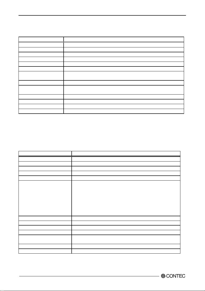
Specifications
Function Specifications
Item Specification
Capacity 40GB *1
Bus interface IDE
Internal drive 2.5-inch hard disk drive
Transfer rate (Max.) 66.6MB/sec (Ultra DMA Mode 4), 16.6MB/sec (PIO Mode 4)
Reliability 1/1013bits read
Connection to PC CPU Module Dedicated 40-pin cable bundled
Extension 40-pin half-pitch connector for connecting slave IDE device
Access indicator *2 Front-panel LED (red)
High-temperature detection Ambient temperature detected:47[+/-]3ºC or higher
External dimensions (mm) 27.4 (W) x 130.0 (D) x 98.0 (H) (Excluding protrusions)
Power consumption +5VDC 0.88A (Max.)
Weight 300g (450g with optional unit fixing brackets attached)
Average life *3 5 years or 20,000 hours of energized time, whichever reached first
*1 1GB = 1,000,000,000bytes
*2 When two disk units (hard disk and/or silicon disk units) are connected in a master/slave arrangement, they have
common access indication. When either of the master and slave devices is accessed, therefore, both of their access
lamps come on at the same time.
*3 Under the assumptions : Less than 333 power on hours per month. And Seeking/Writing/Reading operation is less
than 20% of power on hours.
General Specifications
Item Specification
Operating ambient temperature 5 - 50ºC (at a temperature change rate of 20ºC/h or less)
Storage ambient temperature -25 - 65ºC
Operating ambient humidity 8 - 90% RH (No condensation)
Storage ambient humidity 5 - 95% RH (No condensation)
Maximum wet-bulb temperature 29ºC
Vibration resistance
(during operation)
Shock resistance (during operation) Tested 3 times in each of the X, Y, and Z directions in conformance with JIS
C0041. 49 m/s2, 11 ms
Operating ambiance No corrosive gas
Operating altitude 2000 m or less *3
Installation location Inside the control panel
Over voltage category *1 II or lower
Pollution degree *2 2 or less
*1 The overvoltage category of a device indicates which distributor in the range from public distribution network to
machinery the device is assumed to be connected to. Category II applies to devices to which power is supplied from
fixed facilities. The surge voltage of those devices is 2500 V whose rated voltage is 300 V.
3
Capable of connecting one IDE device with master/slave selector switch
Warning method: High-temperature detection function of bus interface driver software
Tested 10 times (for 45 minutes) in each of the X, Y, and Z directions in
conformance with JIS C0040.
10 - 55 Hz: 0.035 mm
<With the optional hard disk unit fixing brackets attached>
Tested 10 times (for 80 minutes) in each of the X, Y, and Z directions in
conformance with JIS C0040.
10 - 57 Hz: 0.075 mm
57 - 150 Hz: 9.8 m/s
(Do not install the base unit on the DIN rail when the hard disk unit is used.)
2
PPC-HDD(MS)A
Page 4

PPC-HDD(MS)A User's Guide
*2 The index indicating the degree to which conductive substances are generated in the operating environment.
Pollution level 2 indicates the environment that generates only nonconductive pollutants while allowing accidental
condensation to cause temporary conduction.
*3 The hard disk unit may fail and cannot be used in an environment in which the air is compressed to over the
tmospheric pressure generated at an altitude of around 0 m.
External Dimensions
Enhanced IDE interface connector
27.4
IDE interface connector
(For connection to
the PC CPU Module)
4
2982
130
4
[mm]
PPC-HDD(MS)A
4
Page 5

PPC-HDD(MS)A User's Guide
Installing the Hardware
Precautions
Install the hard disk unit on the MELSEC-Q Series base unit before it can be used.
Before using the hard disk unit, be sure to mount the MELSEC-Q Series base unit on the control panel
using screws. Do not use the base unit mounted on the DIN rail.
For mounting the base unit, refer to the “Mitsubishi General-purpose Sequencer QCPU (Q Mode) User’s
Manual (Hardware Design, Maintenance and Inspection)”.
Device is to be powered by limited Voltage/Current circuit of Listed Power Supplies,
Models : Q61P-A1, Q61P-A2, Q61P, Q63P, Q64P, manufactured by Mitsubishi Electric Corp.
Fastening the Hard Disk Unit
- Fit the unit fixing hook in the unit fixing slot in the base unit, then push the hard disk unit in the
direction of the arrow to set the hard disk unit on the base unit
Unit fixing slot
Unit fixing hook
- After setting the hard disk unit on the base unit, be sure to use the attached unit fixing screw to fasten
the hard disk unit to the base unit.
- Tighten the screw within the following torque range.
Tightening torque range: 36 - 48N·cm
If the hard disk unit may be subject to vibration between 4.9 and 9.8 m/s2, use a set of hard disk unit
shock-proof brackets [PPC-HBR-01] available as an option. For installing the base unit with the hard
disk unit on the control panel, refer to the manual for the shock-proof brackets.
5
PPC-HDD(MS)A
Page 6

PPC-HDD(MS)A User's Guide
Functions of Components
Component Locations
Front panel
Access LED
Enhanced(slave) IDE interface connector
Internal disk master/slave selector switch
* Set the first and second disk units as the master and slave devices, respectively.
(When only one disk unit is used, set it as the master device.)
Factory default: M(Master device)
Bottom
(Front)
IDE interface connector
(For connection to the PC CPU Module)
(Rear)
For the pin assignments in the IDE interface and Enhanced IDE interface connectors, refer to the user’s
manual for the PC CPU Module.
PPC-HDD(MS)A
6
Page 7

PPC-HDD(MS)A User's Guide
Master/Slave Arrangement
- PPC-CPU686(MS)
PPC-HDD(MS)A or
PPC-SDD(MS)-xx
ACCESS
PCMCIA
CF
M.
S.
UTP
IDE
(Disk unit)
Master
PPC-HDD(MS)A
(Disk unit)
Master
LINK
/TX
100
Slave
Connect the master and slave disk units
with an IDE connection cable.
Set this to Slave ( S ).
Set this to Master (M).
Slave
Connect the master and slave disk units
with an IDE connection cable.
Set this to Slave (S).
Set this to Master (M ).
PPC-CPU686(MS)
(PC CPU Modul e )
Connect the PC CPU Unit to the master disk unit with an IDE
connection cable.
- PPC-CPU852(MS)
PPC-CPU852(MS)
(PC CPU Module)
PPC-CPU852
KB/MOUSE
B.
RDY
RUN
USER
ERR.
EXIT
BAT.
B.STOP
B.
B.RST
RUN
SERIAL1
RESET
USB
EX.I/F
RGB
CAUTION
USB
Connect the PC CPU Unit to the master disk unit with an IDE
connection cable.
Note!
- Setting the silicon disk unit as the master device involves a restrictions. For details, refer to the
manual for the silicon disk unit.
- To use the hard disk unit along with the dedicated CD-ROM drive [IPC-CDD-02] in a master/slave
arrangement, refer to the manual for the dedicated CD-ROM drive.
7
PPC-HDD(MS)A
Page 8

PPC-HDD(MS)A User's Guide
Average Life of the Hard Disk Drive
The average life of the hard disk drive is 5 years or 20,000 hours of energized time whichever reached first.
High-temperature Detection Feature
Using the hard disk unit in a high-temperature environment shortens the life of the hard disk. The hard
disk unit has a high-temperature detection feature to detect an ambient operating temperature of 47±3°C
or higher using the high-temperature detection function of bus interface driver software. Use this feature
as a means of warning when the hard disk unit is being used at high temperature.
When high-temperature detection is not necessary, you can disable the high-temperature detection
function by setting with the bus interface driver software. In that case, high-temperature detection is not
performed.
For details on this function, refer to the Bus Interface Driver User's Manual [PPC-CPU686(MS)-MU or
PPC-CPU852(MS)-MU, separately priced].
Copyright 2006 CONTEC CO., LTD. ALL RIGHTS RESERVED.
CONTEC CO., LTD. November 2007 Edition
3-9-31, Himesato, Nishiyodogawa-ku, Osaka 555-0025, Japan
Japanese http://www.contec.co.jp/
English http://www.contec.com/ A-51-351 (LYGW823)
Chinese http://www.contec.com.cn/ 11162007_rev3 [10162006]
No part of this document may be copied or reproduced in any form by any means without prior written
consent of CONTEC CO., LTD.
 Loading...