

Contec IPC Series, PC-RSD2000-PCI, PC-RSD1000-PCI, PC-RSD-PCI, PC-RSD4000-PCI User Manual
...Page 1

IPC Series
Silicon Disk Drive with RAID
for PCI
1GB type
PC-RSD1000-PCI
2GB type
PC-RSD2000-PCI
4GB type
PC-RSD4000-PCI
8GB type
PC-RSD8000-PCI
CF uninstalling type
PC-RSD-PCI
User’s Manual
CONTEC CO.,LTD.
Page 2

Check Your Package
Thank you for purchasing the CONTEC product. The product consists of the items listed below.
Check, with the following list, that your package is complete. If you discover damaged or missing
items, contact your retailer.
Product Configuration List
- Product [One of the followings] …1
(PC-RSD-PCI, PC-RSD1000-PCI, PC-RSD2000-PCI, PC-RSD4000-PCI
or PC-RSD8000-PCI)
* CF is appended to each board. (Only PC-RSD-PCI is unappended.)
- First step guide …1
- FD *1 [Driver for the PC-RSD Series] …1
- CompactFlash removal prevention fitting …2
- Scerws …2
*1 : The FD contains the driver software and User’s Guide (this guide).
Product
Screws
PC-RSD Series
First step guide
CompactFlash removal prevention fitting
[Driver for PC-RSD Series]
FD
i
Page 3

Copyright
Copyright 2006 CONTEC CO., LTD. ALL RIGHTS RESERVED
No part of this document may be copied or reproduced in any form by any means without prior written
consent of CONTEC CO., LTD.
CONTEC CO., LTD. makes no commitment to update or keep current the information contained in this
document. The information in this document is subject to change without notice.
All relevant issues have been considered in the preparation of this document. Should you notice an
omission or any questionable item in this document, please feel free to notify CONTEC CO., LTD.
Regardless of the foregoing statement, CONTEC assumes no responsibility for any errors that may
appear in this document nor for results obtained by the user as a result of using this product.
Trademarks
MS, Microsoft, and Windows are trademarks of Microsoft Corporation. Other company and product
names mentioned herein are generally trademarks or registered trademarks of their respective owners.
ii
PC-RSD Series
Page 4

Table of Contents
Check Your Package ............................................................................................................................... i
Copyright .................................................................................................................................................ii
Trademarks ..............................................................................................................................................ii
Table of Contents ...................................................................................................................................iii
1. BEFORE USING THE PRODUCT 1
About the Board ......................................................................................................................................1
Features............................................................................................................................................. 1
Accessories (Option)..................................................................................................................... 1
Customer Support.................................................................................................................................... 2
Web Site ........................................................................................................................................... 2
Limited One Year Warranty ...................................................................................................................2
How to Obtain Service ............................................................................................................................ 2
Liability ...................................................................................................................................................2
Safety Precautions................................................................................................................................... 3
Safety Information ........................................................................................................................... 3
Handling Precautions .......................................................................................................................3
Environment ..................................................................................................................................... 5
Inspection ......................................................................................................................................... 5
Storage .............................................................................................................................................. 5
Disposal ............................................................................................................................................5
2. SETUP 7
What is Setup?......................................................................................................................................... 7
Step 1 Setting the Hardware ...................................................................................................................8
Parts of the Board............................................................................................................................. 8
Plugging the Board........................................................................................................................... 8
Step 2 Installing the Hardware ............................................................................................................. 10
Mounting this product on Windows XP installed PC....................................................................... 10
Turning on the PC .......................................................................................................................... 10
Setting the “Found New Hardware Wizard”................................................................................. 10
Check Method of Hardware Install Completion ...........................................................................12
Installing Windows XP newly on a hard disk or this product.......................................................... 13
Installing drivers while installing Windows XP newly ................................................................13
Check Method of Hardware Install Completion ...........................................................................14
Mounting this product on Windows 2000 installed PC.................................................................... 15
Turning on the PC .......................................................................................................................... 15
Setting the “Found New Hardware Wizard”................................................................................. 15
Check Method of Hardware Install Completion ...........................................................................18
PC-RSD Series
iii
Page 5

Installing Windows 2000 newly on a hard disk or this product .......................................................19
Installing drivers while installing Windows 2000 newly..............................................................19
Check Method of Hardware Install Completion ...........................................................................20
Setup Troubleshooting...........................................................................................................................21
Symptoms and Actions...................................................................................................................21
If your problem cannot be resolved ...............................................................................................21
3. FUNCTION 23
IDE Function..........................................................................................................................................23
RAID Function ......................................................................................................................................23
RAID 0 (Striping)...........................................................................................................................23
RAID 1 (Mirroring) ........................................................................................................................23
JBOD [Just Bunch Of Disks] (Spanning)......................................................................................23
4. ABOUT THE RAID BUILDING SOFTWARE 25
Setup Utility...........................................................................................................................................25
Start up the Setup Utility................................................................................................................25
Building a striping (RAID 0) .........................................................................................................27
Building a new mirroring (RAID 1) using two CFs......................................................................30
Setting the CF which has already been used and added to mirroring (RAID 1).......................33
Building a Spanning .......................................................................................................................37
Canceling RAID Setting.................................................................................................................40
RaidMgr Utility......................................................................................................................................41
Installing RaidMgr Utility..............................................................................................................41
Starting RaidMgr ............................................................................................................................42
Building a striping (RAID 0) .........................................................................................................43
Building a mirroring (RAID 1) ......................................................................................................45
Building a spanning (JBOD)..........................................................................................................47
Screen details on RaidMgr .............................................................................................................49
Delete the built RAID.....................................................................................................................50
Rebuilding a mirror disk ................................................................................................................51
If failing a CF in mirroring.............................................................................................................52
Uninstalling the support software and driver .......................................................................................55
Uninstalling the support software [RaidMgr]................................................................................55
Uninstalling the driver....................................................................................................................56
Contents of FD.......................................................................................................................................57
5. ABOUT HARDWARE 59
Hardware specification..........................................................................................................................59
About Rewrite Life ................................................................................................................................60
iv
PC-RSD Series
Page 6

1. Before Using the Product
1. Before Using the Product
This chapter provides information you should know before using the product.
About the Board
This product is a PCI board type silicon disk drive. It can be used the same as a hard disk by mounting
it to a PCI bus slot of your PC. With a CompactFlash Memory Card (CF) with FIX DISK specification
adopted as the storage media, this product, as a disk drive as an alternative to a hard disk, is the most
suitable for the system which requires reliability and tough operation conditions such as
around-the-clock operation, environment resistances (to temperature, humidity, vibration and shock),
and quietness. Since this product has two CF slots, an additional drive can be mounted (capacity
upgrade) by adding a CF (option). Also, RAID drive configurations for striping [RAID 0], mirroring
[RAID 1], and spanning [JBOD] are possible by adding a CF and using utilities.
Features
- Just like a hard disk, this product can be used as an add-on drive for PC main body or the CF of this
product can be used as OS boot disk drive. Also, it can be used as two drives by adding an option
CF.
- Unlike a hard disk, there is no rotating/moving parts, making most suitable for the uses requiring
tough environment resistances (to temperature, humidity, vibration and shock) and for long
continuous operations.
- An add-on CF slot exists at the PCI blanket part, offering facilities of adding and exchanging of an
option CF even after this product is mounted to PC.
- Three types of RAID functions *1 [RAID 0 (striping), RAID 1 (mirroring), and JBOD (spanning)]
are available by adding a CF to the add-on CF slot and using utilities.
*1 RAID configurations in a hard disk which is connected to PC can not be made.
Accessories (Option)
CompactFlash 1GB (FIX DISK specification) : CF-1GB-R
CompactFlash 2GB (FIX DISK specification) : CF-2GB-R
CompactFlash 4GB (FIX DISK specification) : CF-4GB-R
CompactFlash 8GB (FIX DISK specification) : CF-8GB-R
PC-RSD Series
1
Page 7

1. Before Using the Product
Customer Support
CONTEC provides the following support services for you to use CONTEC products more efficiently
and comfortably.
Web Site
Japanese http://www.contec.co.jp/
English http://www.contec.com/
Chinese http://www.contec.com.cn/
Latest product information
CONTEC provides up-to-date information on products.
CONTEC also provides product manuals and various technical documents in the PDF.
Free download
You can download updated driver software and differential files as well as sample programs available in
several languages.
Note! For product information
Contact your retailer if you have any technical question about a CONTEC product or need its price,
delivery time, or estimate information.
Limited One Year Warranty
CONTEC products are warranted by CONTEC CO., Ltd. to be free from defects in material and
workmanship for up to one year from the date of purchase by the original purchaser.
Repair will be free of charge only when this device is returned freight prepaid with a copy of the
original invoice and a Return Merchandise Authorization to the distributor or the CONTEC group office
from which it was purchased.
This warranty is not applicable for scratches or normal wear, but only for the electronic circuitry and
original products. The warranty is not applicable if the device has been tampered with or damaged
through abuse, mistreatment, neglect, or unreasonable use, or if the original invoice is not included, in
which case repairs will be considered beyond the warranty policy.
How to Obtain Service
For replacement or repair, return the device freight prepaid, with a copy of the original invoice. Please
obtain a Return Merchandise Authorization number (RMA) from our Sales Administration Department
before returning any product.
* No product will be accepted by CONTEC group without an RMA number.
Liability
The obligation of the warrantor is solely to repair or replace the product. In no event will the warrantor
be liable for any incidental or consequential damages due to such defect or consequences that arise from
inexperienced usage, misuse, or malfunction of this device.
2
PC-RSD Series
Page 8

1. Before Using the Product
Safety Precautions
Understand the following definitions and precautions to use the product safely.
Safety Information
This document provides safety information using the following symbols to prevent accidents resulting in
injury or death and the destruction of equipment and resources. Understand the meanings of these
labels to operate the equipment safely.
DANGER
WARNING
CAUTION
Handling Precautions
DANGER
Do not use the product where it is exposed to flammable or corrosive gas. Doing so may result in
an explosion, fire, electric shock, or failure.
DANGER indicates an imminently hazardous situation which, if not avoided, will
result in death or serious injury.
WARNING indicates a potentially hazardous situation which, if not avoided, could
result in death or serious injury.
CAUTION indicates a potentially hazardous situation which, if not avoided, may
result in minor or moderate injury or in property damage.
CAUTION
- Do not strike or bend the board.
Otherwise, the board may malfunction, overheat, cause a failure or breakage.
- Do not touch the board's metal plated terminals (edge connector) with your hands.
Otherwise, the board may malfunction, overheat, or cause a failure.
If the terminals are touched by someone's hands, clean the terminals with industrial alcohol.
- Do not install or remove the board to or from the slot while the computer's power is turned on.
Doing so could cause trouble. Be sure that the personal computer or the I/O expansion unit power
is turned off.
- Make sure that your PC or expansion unit can supply ample power to all the boards installed.
Insufficiently energized boards could malfunction, overheat, or cause a failure.
- No part of this document may be copied or reproduced in any form by any means without prior
written consent of CONTEC CO., LTD.
- The specifications of this product are subject to change without notice for enhancement and quality
improvement.
Even when using the product continuously, be sure to read the manual and understand the contents.
- All relevant issues have been considered in the preparation of this document. Should you notice
an omission or any questionable item in this document, please feel free to notify CONTEC CO.,
LTD.
PC-RSD Series
3
Page 9

1. Before Using the Product
- Do not modify the product. CONTEC will bear no responsibility for any problems, etc., resulting
from modifying this product.
- Regardless of the foregoing statements, CONTEC is not liable for any damages whatsoever
(including damages for loss of business profits) arising out of the use or inability to use this
CONTEC product or the information contained herein.
- Do not turn off the power during disk access (when rewriting).
Otherwise, CF in the product and the data contained in the CF may be damaged.
- The silicon disk may malfunction if this product instantaneously stops during a write operation.
For this reason, the product has a protection circuit that minimizes disk failures during an
instantaneous stop. Use UPS as a complete countermeasure for instantaneous stop problems.
- This product does not operate properly, when combined with our SBC [PC-686C(PC)H series].
- CF has a limitation for the number of times to rewrite, due to the memory used. This write
tolerance depends on the actual use conditions.
- Use only the supplied option CF (CF-xGB-R) for the expansion CF. CONTEC will bear no
responsibility for any problems, etc., resulting from using the commercially available CF.
- The operation of this product has been checked in combination with our other products. Use the
product within the scope of your responsibilities when using it in combination with products from
other companies.
4
PC-RSD Series
Page 10

1. Before Using the Product
Environment
Use this product in the following environment. If used in an unauthorized environment, the board may
overheat, malfunction, or cause a failure.
Operating temperature
0 - 50°C
Operating humidity
10 - 90%RH (No condensation)
Corrosive gases
None
Floating dust particles
Not to be excessive
Inspection
Inspect the product periodically as follows to use it safely.
- Check that the bus connector
of the board and its cable have
been plugged correctly.
- Check that the board has
no dust or foreign matter adhering.
- The gold-plated leads of the bus connector
have no stain or corrosion.
Storage
When storing this product, keep it in its original packing form.
(1) Put the board in the storage bag.
(2) Wrap it in the packing material, then put it in the box.
(3) Store the package at room temperature at a place free from direct sunlight, moisture, shock,
vibration, magnetism, and static electricity.
Disposal
When disposing of the product, follow the disposal procedures stipulated under the relevant laws and
municipal ordinances.
PC-RSD Series
5
Page 11

1. Before Using the Product
6
PC-RSD Series
Page 12

2. Setup
2. Setup
This chapter explains how to set up the board.
What is Setup?
Setup means a series of steps to take before the product can be used.
Different steps are required for software and hardware.
The setup procedure varies with the OS and applications used.
Follow the steps shown in this chapter to prepare hardware and software.
Step 1 Setting the Hardware
This section describes the setup procedure to mount this product on your PC.
Please note that CFs should be removed in advance before Windows is newly installed on the hard disk
or before this product is added to your PC on which Windows is currently installed.
If this product is used under DOS in MS-DOS Version 6.2, IBM PC DOS 2000 J7.0/V or PC DOS 7,
only the setup “Step 1” is required. If it is used under Windows, proceed to “Step 2” after “Step 1” is
completed. Other OSs are not supported. For the supported OS types, see “Chapter 5 About
Hardware”.
Step 2 Installing the Hardware
This section describes the setup procedure for this product if used as a disk drive under Windows.
If Setup fails to be performed normally, see the “Setup Troubleshooting” section at the end of this
chapter.
CAUTION
- When using under DOS, the disk capacity limit (2GB) is applied. For 4GB and 8GB CFs, the
remaining capacity can be used by dividing it to expanded partitions.
Also under DOS, RAID configuration is not allowed in either CFs.
- More than one product cannot be used on the same PC.
After completing the setup for this product having an add-on CF, the system will recognize it as two
disk drives. The drive mapping depends on your PC conditions (BIOS setting and IDE device
connection status).
CAUTION
Shut down the system before attaching/removing CFs.
PC-RSD Series
7
Page 13

2. Setup
Step 1 Setting the Hardware
This section describes how to set the board and plug it on your PC.
Remove CFs in advance before Windows is newly installed on the hard disk or before this product is
added to your PC on which Windows is currently installed.
Parts of the Board
Figure 2.1. shows the names of major parts on the board.
CF Access LED
CF removal prevention fitting
Figure 2.1. Part Names
CF removal prev e ntion fitting
CF Slot (Primary master)
CF has been
mounted.
CF Slot for expansion (Seconfary master)
Plugging the Board
(1) If OS is preinstalled, shutdown the system before mounting this board.
(2) Unplug the power code of your PC from the wall
outlet.
(3) Remove the cover from the PC. For instructions on
how to remove, refer to the user’s guide for your PC.
(4) Remove the PCI slot cover so that the board can be
mounted.
(5) If OS is DOS or a new OS is installed to the CF of
this product, proceed to step (6).
If Windows is newly installed to a hard disk or
Windows is currently installed on your PC, remove the mounted CF from this board.
(6) Plug the board into an expansion slot.
8
PC-RSD Series
Page 14

2. Setup
(7) Attach the board bracket to the PC with a screw.
(8) If OS is DOS or a new OS is installed to the CF of this product, check if the CF is mounted on this
product and then put the cover back into place. If Windows is newly installed to a hard disk or
this product is added to the PC on which Windows is currently installed, proceed to “Step 2
Installing the Hardware”, mount the CF on the slot where it was originally mounted on and then put
the cover back into place.
(9) If OS is DOS, after completing the board mounting, turn on the PC. A message saying “IT8212
RAID... ” will be displayed after a period of time. At this time, RAID setting is not performed, so
continue the startup by pressing [Esc] key. Without pressing [Esc], the status will become startup
status after a period of time. After the startup, this product can be used as an IDE device.
Applicable PCI bus slots
PCI bus slots used in PCs have keys to prevent 5V and 3.3V PCI bus boards from being accidentally
plugged into wrong bus slots. This board can be plugged into both of the 5V and 3.3V PCI bus slots.
<PCI bus slo t> <PCI bus bo ard>
5-V PCI bus slot
3.3-V PCI bus slot
3.3V key
CAUTION
5V key
A :
Slit for 5-V PCI bus slot
B :
Slit for 3.3-V PCI bus slot
AB
- Do not touch the board's metal plated terminals (edge connector) with your hands.
Otherwise, the board may malfunction, overheat, or cause a failure.
If the terminals are touched by someone's hands, clean the terminals with industrial alcohol.
- Do not install or remove the board to or from the slot while the computer's power is turned on.
Otherwise, the board may malfunction, overheat, or cause a failure.
Doing so could cause trouble. Be sure that the personal computer or the I/O expansion unit power is
turned off.
- Make sure that your PC or expansion unit can supply ample power to all the boards installed.
Insufficiently energized boards could malfunction, overheat, or cause a failure.
- Power supply from the PCI bus slot at +5V is required.
PC-RSD Series
9
Page 15

2. Setup
Step 2 Installing the Hardware
Windows needs to detect the I/O address and interrupt used by the board. This is called hardware
installation. The procedure is different for each OS. Install the hardware according to the respective
procedure.
After the hardware installation is completed, the hardware can be used as a disk drive on Windows.
Mounting this product
on Windows XP installed PC
Turning on the PC
After mounting the board in “Step 1 Setting the Hardware ” and checking if the CF has been removed,
turn on your PC. After a period of time, a message saying “IT8212 RAID... ” will be displayed at the
startup. At this time, RAID setting is not performed, so continue the startup by pressing [Esc] key.
Without pressing [Esc], the status will become startup status after a period of time. Log on as a user
with administrative privileges of the PC after Windows startup.
CAUTION
- The board cannot be properly installed unless the resources (I/O addresses and interrupt level) for
the board can be allocated. Before attempting to install the board, first determine what PC
resources are free to use.
- More than one product cannot be used on the same PC.
Setting the “Found New Hardware Wizard”
(1) The “Found New Hardware Wizard” will be
started. Click the [Next] button after checking
the “No, not this time”.
If using Windows XP with no SP2 (Service
Pack 2) installed, this window will not be
displayed. Proceed to (2).
10
(1) Select
(2) Click
PC-RSD Series
Page 16

(2) The “Found New Hardware Wizard” will be
started. Select “Install from a list or specific
location[Advanced]”, then click on the [Next]
button.
(3) Select “Search for the best driver in these
locations.” and then check only the
“Include this location in the search:”.
(4) Insert the supplied Driver FD into the floppy
disk drive, specify the following folder, and
press [Next] button.
- Source folder A:\WINXP
(5) Click the [Continue Anyway] button after the
“Hardware Installation” is displayed.
2. Setup
(1) Select
(2) Click
(1) Select
(2) Specify
(3) Click
(6) Click the [Finish] button.
PC-RSD Series
Click
Click
11
Page 17

2. Setup
(7) If the “System Settings Changes”is displayed, click the [No] button.
Click
CAUTION
In Windows XP, the Hardware Wizard displays the following alert dialog box when you have
located the INF file. This dialog box appears, only indicating that the relevant driver has not
passed Windows Logo testing, and it can be ignored without developing any problem with the
operation of the board.
You have now finished installing the Hardware.
Shutdown the system and mount the removed CF back to the slot.
In this case, click on the [Continue Anyway] button.
Check Method of Hardware Install Completion
(1) Click the [Start] button on the left side of task bar
and then right-click the [My Computer] or it on the
desktop side.
(2) Click the [Propaties] on the menu.
(3) When the [System propaties] is displayed, click the
[Hardware] tab and then click the [Device
Manager].
(4) Check if the board name has been registered
correctly in [SCSI and RAID controllers].
(5) Check if [ITE Disk Array 0 SCSI Disk Device] has
been registered in [Disk Drives].
After checking that it has been registered for disk drive,
you can now use it as a disk drive. The drive mapping depends on your PC conditions (BIOS setting
and IDE device connection status).
CAUTION
When formatting a CF in Windows XP, do not format it as “dynamic disk”.
Once formatted as “dynamic disk”, the CF cannot be used on other PCs or OSs.
12
PC-RSD Series
Page 18

Installing Windows XP newly
on a hard disk or this product
2. Setup
CAUTION
- When installing drivers of this product while installing Windows XP newly on a hard disk, remove
the CF of this product in Step 1. When installing Windows XP on the CF of this product, do not
remove the CF in Step 1.
- The board cannot be properly installed unless the resources (I/O addresses and interrupt level) for
the board can be allocated. Before attempting to install the board, first determine what PC
resources are free to use.
- More than one product cannot be used on the same PC.
- When installing OS on this product, make sure to prepare the CF having the capacity larger than
that required by OS.
Installing drivers while installing Windows XP newly
(1) After completing the board mounting, turn on the PC. A message saying “IT8212 RAID... ” will
be displayed after a period of time. At this time, RAID setting is not performed, so press [Esc]
key. Without pressing [Esc] key, the status will become startup status after a period of time.
(2) When installing from floppy disk, start up your PC from the “Windows XP installation disk”.
When installing from CD-ROM, start up you PC from CD-ROM.
When a message “Press F6 if you need to install third party SCSI or RAID driver” is displayed,
press [F6] key.
(3) After [Windows XP setup] is displayed, press [S] key to specify a driver you want to add.
(4) Insert the supplied Driver FD into the floppy drive and press [Enter] key.
(5) Select “CONTEC PC-RSD Series (Windows XP)” from a list displayed on the screen and press
[Enter] key.
(6) [Windows XP setup] screen is displayed again and a message saying “Setup will load support for
the following mass storage device(s)” is displayed. [
is now included in this list.
If any additional device you want to install, specify it now. If all devices are specified, proceed
to the next step.
(7) Press [Enter] key on [Windows XP setup] screen to continue the Windows XP installation. In the
middle of installation, the Windows XP installation location can be selected from either the CF of
this product or PC hard disk.
CONTEC PC-RSD Series (Windows XP)
]
PC-RSD Series
13
Page 19

2. Setup
CAUTION
In Windows XP, the Hardware Wizard displays the following alert dialog box of [Installng
Software], [Installing Hardware]. This dialog box appears, only indicating that the relevant driver
has not passed Windows Logo testing, and it can be ignored without developing any problem with
the operation of the board.
You have now finished installing the Hardware.
After installing Windows XP on the hard disk, shutdown the system and mount the removed CF back to
the slot.
In this case, click on the [Yes] button.
Check Method of Hardware Install Completion
(1) Click the [Start] button on the left side of task bar
and then right-click the [My Computer] or it on the
desktop side.
(2) When the [System propaties] is displayed, click the
[Hardware] tab and then click the [Device
Manager].
(3) Check if the board name has been registered
correctly in [SCSI and RAID controllers].
(4) Check if [ITE Disk Array 0 SCSI Disk Device] has
been registered in [Disk Drives].
After checking that it has been registered for disk drive, you can now use it as a disk drive. The drive
mapping depends on your PC conditions (BIOS setting and IDE device connection status).
CAUTION
When formatting a CF in Windows XP, do not format it as “dynamic disk”. Once formatted as
“dynamic disk”, the CF cannot be used on other PCs or OSs.
14
PC-RSD Series
Page 20

2. Setup
Mounting this product
on Windows 2000 installed PC
Turning on the PC
After mounting the board in “Step 1 Setting the Hardware ” and checking if the CF has been removed,
turn on your PC. A message saying “IT8212 RAID... ” will be displayed after a period of time. At
this time, RAID setting is not performed, so press [Esc] key. Without pressing [Esc] key, the status
will become startup status after a period of time. Log on as administrator after Windows startup.
CAUTION
- The board cannot be properly installed unless the resources (I/O addresses and interrupt level) for
the board can be allocated. Before attempting to install the board, first determine what PC
resources are free to use.
- More than one product cannot be used on the same PC.
Setting the “Found New Hardware Wizard”
(1) The “Found New Hardware Wizard” will be
started. Click the [Next] button
(2) Select “Search for a suitable driver for my
device [recommended]” and then check the
[Next] button.
PC-RSD Series
Click
(1) Select
(2) Click
15
Page 21

2. Setup
(3) Select only the “Specify a location” and then
click the [Next] button.
(1) Specify
(2) Click
(4) Insert the supplied Driver FD into the floppy
drive, spcify the following source folder and
then click [OK] button.
- Source folder A:\WIN2K
(5) This product is found. Click [Next] button.
(6) If the “Digital Signature Not Found” is displayed,
click the [Yes] button.
(2) Click
(1) Specify
Click
Click
16
PC-RSD Series
Page 22

(7) Click the [Finish] button.
(8) If the “System Setting Change” is
displayed, click the [No] button.
2. Setup
Click
Click
CAUTION
In Windows 2000, the Hardware Wizard displays the following alert dialog box when you have
located the INF file. This dialog box appears, only indicating that the relevant driver has not
passed Windows Logo testing, and it can be ignored without developing any problem with the
operation of the board.
You have now finished installing the Hardware.
Shutdown the system and mount the removed CF back to the slot.
In this case, click on the [Yes] button.
PC-RSD Series
17
Page 23

2. Setup
Check Method of Hardware Install Completion
(1) Click the [Start] button on the left side of task bar and
then double click the [System] from the
[Setting]→[Control Panel].
(2) When the [System propaties] is displayed, click the
[Hardware] tab and then click the [Device Manager].
(3) Check if the board name has been registered correctly in
[SCSI and RAID controllers].
(4) Check if [ITE Disk Array 0 SCSI Disk Device] has been
registered in [Disk Drives].
After checking that it has been registered for disk drive, you can now use it as a disk drive. The drive
mapping depends on your PC conditions (BIOS setting and IDE device connection status).
CAUTION
When formatting a CF in Windows XP, do not format it as “dynamic disk”. Once formatted as
“dynamic disk”, the CF cannot be used on other PCs or OSs.
18
PC-RSD Series
Page 24

Installing Windows 2000 newly
on a hard disk or this product
2. Setup
CAUTION
- When installing drivers of this product while installing Windows 2000 newly on a hard disk,
remove the CF of this product in Step 1. When installing Windows XP on the CF of this product,
do not remove the CF in Step 1.
- The board cannot be properly installed unless the resources (I/O addresses and interrupt level) for
the board can be allocated. Before attempting to install the board, first determine what PC
resources are free to use.
- More than one product cannot be used on the same PC.
- When installing OS on this product, make sure to prepare the CF having the capacity larger than
that required by OS.
Installing drivers whil e installing Windows 2000 newly
(1) After completing the board mounting, turn on the PC. A message saying “IT8212 RAID... ” will
be displayed after a period of time. At this time, RAID setting is not performed, so press [Esc]
key. Without pressing [Esc] key, the status will become startup status after a period of time.
(2) When installing from floppy disk, start up your PC from the “Windows 2000 installation disk”.
When installing from CD-ROM, start up you PC from CD-ROM.
When a message “Press F6 if you need to install third party SCSI or RAID driver” is displayed,
press [F6] key.
(3) After [Windows 2000 setup] is displayed, press [S] key to specify a driver you want to add.
(4) Insert the supplied Driver FD into the floppy drive and press [Enter] key.
(5) Select “
(6) [Windows 2000 setup] screen is displayed again and a message saying “Setup will load support for
CONTEC PC-RSD Series (Windows 2000)
[Enter] key.
the following mass storage device(s)” is displayed. [
(Windows 2000)
If any additional device you want to install, specify it now. If all devices are specified, proceed
to the next step.
] is now included in this list.
” from a list displayed on the screen and press
CONTEC PC-RSD Series
PC-RSD Series
19
Page 25

2. Setup
(7) Press [Enter] key on [Windows 2000 setup] screen to continue the Windows 2000 installation. In
the middle of installation, the Windows 2000 installation location can be selected from either the
CF of this product or PC hard disk. The message “Cannot find digital signature” appears in the next
window. Ignore this and click “Yes”.
CAUTION
In the middle of installation of the Windows 2000, the Hardware Wizard displays the alert dialog
box. This dialog box appears, only indicating that the relevant driver has not passed Windows
Logo testing, and it can be ignored without developing any problem with the operation of the board.
In this case, click on the [Yes] button.
You have now finished installing the Hardware.
After installing Windows 2000 on the hard disk, shutdown the system and mount the removed CF back
to the slot.
Check Method of Hardware Install Completion
(1) Click the [Start] button on the left side of task bar
and then double click the [System] from the
[Setting]→[Control Panel].
(2) When the [System propaties] is displayed, click the
[Hardware] tab and then click the [Device
Manager].
(3) Check if the board name has been registered
correctly in [SCSI and RAID controllers].
(4) Check if [ITE Disk Array 0 SCSI Disk Device] has
been registered in [Disk Drives].
Once it is verified that the hardware is listed on Disk Drive, it can be used as a disk drive. Drive
mapping depends on the state of the PC used (BIOS settings and IDE device connection status).
CAUTION
When formatting CF on Windows 2000, do not format it as a “dynamic disk”. If CF is formatted as
a “dynamic disk”, it cannot be used on other PCs or OSs.
20
PC-RSD Series
Page 26

2. Setup
Setup Troubleshooting
Symptoms and Actions
PC does not start up after this product has been mounted.
This product does not work.
”!” mark is shown in [Device manager].
Make sure that this product is attached correctly.
Check if there is any shortage of resources allocatable to this product.
When using a board not compliant with Plug and Play, change the resource allocation for the board. If
the resource cannot be changed, use both the board and this product as the situation demands.
The resource may be conflicted to other peripheral devices. Check the settings of the expanded
peripheral device.
Check the boot device order to see if the setting is made so that OS is booted from the device where OS
is installed.
PC operation is unstable.
Change the PCI slot location for mounting this product.
This product is not registered in the disk drive.
The product cannot be registered in the [disk drive] of the [device manager], when installed in the PCI-
to-PCI Bridge environment.
Mirroring (RAID1) cannot be built for the OS startup drive.
When building mirroring in PC-RSD1000/2000/4000-PCI (when only one copy of the attached CF is
used), the OS will not start up, if such mirroring configuration is performed after the OS is installed to
the attached CF. Therefore, make sure to add another CF when building mirroring. For more details,
refer to “Building a new mirroring (RAID 1) using two CFs”.
If your problem cannot be resolved
Contact your retailer.
PC-RSD Series
21
Page 27

2. Setup
22
PC-RSD Series
Page 28

3. Function
3. Function
This chapter explains the function equipped with the board.
IDE Function
The CFs mounted on this product can be used as normal IDE disk drives.
They are connected as two drives on the installed RAID controller. The internal CF is connected as the
primary master and the external CF (blanket side) is connected as the secondary master. Booting is
possible from each CF, however, it may be required to change settings for the startup order in the BIOS
setting of your PC. For details on the setting changes, refer to the user’s guide for your PC.
RAID Function
RAID functions are available by mounting an option CF on the add-on CF slot (blanket side) and using
utilities.
RAID 0 (Striping)
- This RAID allows the system to speed up the access speed by combining two disks for executing
the reading/writing processes from/to more than one disk in parallel (concurrently).
CAUTION
- If the disk capacity is different between disks, you cannot use the total capacity of all disks in RAID
0. It is recommended to use disks having the same capacity.
- Since the redundancy is not provided at all, the access to all disks will be disabled if one of the
disks in the RAID 0 operation is failed.
RAID 1 (Mirroring)
- This RAID writes the same data to more than one disk, allowing the system to continue the
processes using others if one disk is failed. It prepares a “copy” of disk in which the same data is
stored in anticipation of failure.
- The usability of the disk capacity will be less than 50% since the same data is written to two disks.
(Since the capacity depends on the smaller one, if the two disks have the different capacities, the
usability will become even lower.)
JBOD [Just Bunch Of Disks] (Spanning)
- This technology combines multiple disks to pretend them as a single large capacity disk.
- There is no mechanism of redundancy code, such as parity, nor fault tolerance.
- The performance is enhanced in RAID 0 by reading from/writing to multiple disks in parallel, while
on the other hand, JBOD performs a reading from/writing to process one by one, the performance is
not improved.
- Even if the capacity of each disk is different, a single virtual disk can be realized without wasting
any capacities.
PC-RSD Series
23
Page 29

3. Function
24
PC-RSD Series
Page 30

4. About the RAID Building Software
4. About the RAID Building Software
To build RAID, a new CF should be mounted on the add-on CF slot of this product.
After mounting an additional CF, RAID can be built using utilities. For RAID configuring utilities,
“Setup Utility” which can be operated from the PC startup screen and “RaidMgr” which can be operated
on Windows are available.
If OS is installed on a CF of this product, you cannot use “RaidMgr” which can be operated on
Windows. Use “Setup Utility” which can be operated from the PC startup screen. When this product
is used for applications other than OS or for data storage disk, for your convenience, use the utility
application software “RaidMgr” which can be operated on Windows. The followings are the
descriptions for the case when CF-1GB-R is additionally mounted on PC-RSD1000-PCI.
CAUTION
When formatting CF on Windows 2000, Windows XP, do not format it as a “dynamic disk”. If CF
is formatted as a “dynamic disk”, it cannot be used on other PCs or OSs.
Setup Utility
Start up the Setup Utility
(1) Start your PC after mounting the CF on this product.
(2) After a while, the screen shown below is displayed at the PC startup.
At this time, press [F] key or [E] key while pressing [Ctrl] key.
IT8212 RAID BIOS V1.7.1.94 F/W Ver 02093030
Copyright 2002 - 2005 ITE, Inc. All Right Reserved
Please wait for IDE scan..
Device 0 : SanDisk SDCFH - 1024 IDE 0
Device 1 : Not Detected
Device 2 : SanDisk SDCFH - 1024 IDE 2
Device 3 : Not Detected
Press <Ctrl - F> or <Ctrl - E> to enter Setup Utility or
Press <ESC> or <S> to continue booting……………..
PC-RSD Series
25
Page 31

4. About the RAID Building Software
(3) The following screen is displayed. First, check to see if CFs are connected correctly.
Press [5] key to start [RAID Card Configuration].
IT8212 Setup Utility (C) Copyright 2002 - 2004 ITE, Inc.
[Main Menu]
Auto Configuration………………….[1]
Define RAID………………………...[2]
Delete RAID………………………...[3]
Rebuild RAID……………………….[4]
RAID Card Configuration…………..[5]
[1]..[5] Select [ESC] Exit
(4) Check if the connected CFs are displayed in [Drive Status] field.
IT8212 Setup Utility (C) Copyright 2002 - 2004 ITE, Inc.
[RAID Card Configuration]
Auto Rebuild :
[RAID Card Resource]
Channel 0 Interrupt : A
Channel 1 Interrupt : A I/O Port : 8888D000
[Deive Status]
Channel Size Drive
ID Drive Name (MB) Array No. Mode
Pri/D0 SanDisk SDCFH - 1024 977 Free D2
Enable
I/O Port : 0000DC00
Sec/D0 SanDisk SDCFH - 1024 977 Free D2
* : Capacity (GB) Drive Mode : P = PIO, D = DMA U = UDMA
[→, ←, Space] Change Option [ESC] Exit
CAUTION
[Pri/D0] indicates Primary Master (internal CF) and [Sec/D0] indicates Secondary Master (external
CF).
26
PC-RSD Series
Page 32

4. About the RAID Building Software
Building a striping (RAID 0)
(1) After starting Setup Utility, press [2] key in [Setup Utility] main menu.
Auto Configuration………………….[1]
Define RAID………………………...[2]
Delete RAID………………………...[3]
Rebuild RAID……………………….[4]
RAID Card Configuration…………..[5]
(2) On [Define RAID Menu] screen, select an unset [Array No] using [↑][↓] keys and then press
[Enter] key.
IT8212 Setup Utility (C) Copyright 2002 - 2004 ITE, Inc.
[Define RAID Menu]
Array No. Array Mode Drive No. Size(MB) Status
Array 0 --- --- --- --Array 1 --- --- --- --Array 2 --- --- --- --Array 3 --- --- --- ---
* : Capacity (GB) ♦ : Bootable Array
[↑] Up [↓] Down [Space] Boot Array [Enter] Select [ESC] Exit
Press [2] and start up the
[Define RAID].
PC-RSD Series
27
Page 33

4. About the RAID Building Software
(3) Set each setting item.
Move to another item using [↑][↓] keys. The value can be changed for each item using [Space] key.
Setting item Setting value
Array Mode Stripe
Block Size Set the dividing size for data.
Drive Assignment [Y] : Striping is set
The performance will be improved by using the optimum
value. The optimum value, however, is different depending
on the usage environment.
Setting value : 1K, 2K, 4K, 8K, 16K, 32 K, 64K
(Initial value [64KB], recommended value [32KB])
[N] : Striping is not set
Change the setting
for each item using
[Space] key.
IT8212 Setup Utility (C) Copyright 2002 - 2004 ITE, Inc.
[Define RAID Sub-Menu]
(1) Select [Stripe].
Array No. Array Mode Drive No. Status
Array B
Block Size 64 KB
Stripe
0 Non-functional
(2) Select Block Size.
[Drive Assignments]
Channel
(3) Set to [Y].
ID Drive Name Size (MB) Assignment
Pri/D0 SanDisk SDCFH - 1024 977 Y
Sec/D0 SanDisk SDCFH - 1024 977 Y
* : Capacity (GB)
[↑] Up [↓] Down [Space] Change Option [Ctrl-Y] Save [ESC] Exit
After the setting, press [Ctrl-Y] (press [Y] key while pressing [Ctrl] key).
28
PC-RSD Series
Page 34

4. About the RAID Building Software
(4) Press [Y] key to set striping.
The data of the selected CF will be erased upon selecting striping for the CF by pressing [Y] key
and the data cannot be restored.
Erase old data in this new array?
Y - Yes / N - No
CAUTION
- The data of the CF will be erased upon pressing [Y] key and the data cannot be restored.
- When [N] is pressed, the partition information for the CF and other data will not be erased, but
since the striping information is being set, they cannot be restored. However, they can be restored
if RAID is cancelled before any formatting or writing is made on the CF. For instructions on how
to cancel RADI, see “Chapter 4 Canceling RAID Setting”. If the following message is displayed
while canceling RAID, press [N] key.
Erase the data in the array?
Y - Yes / N - No
(5) Press [Esc] key to return to [Define RAID Menu].
(6) After checking that the striping has been set, press [Esc] key.
Array No. Array Mode Drive No. Size(MB) Status
Array 0 Stripe 2 1954 Functional
(7) Press [Esc] key in [Setup Utility] main menu.
Auto Configuration………………….[1]
Define RAID………………………...[2]
Delete RAID………………………...[3]
Rebuild RAID……………………….[4]
RAID Card Configuration…………..[5]
(8) When you are asked whether to exit [Setup Utility], press [Y] key to exit [Setup Utility].
Exit Setup Utility! Are you sure?
Press Y to exit or ANY KEY to go back.
(9) Your PC will be rebooted. After Windows startup, format the CF which striping has been set.
When formatting, the established two CFs will be formatted.
[Define RAID Menu]
PC-RSD Series
29
Page 35

4. About the RAID Building Software
Building a new mirroring (RAID 1) using two CFs
(1) After starting Setup Utility, press [2] key in [Setup Utility] main menu.
Auto Configuration………………….[1]
Define RAID………………………...[2]
Delete RAID………………………...[3]
Rebuild RAID……………………….[4]
RAID Card Configuration…………..[5]
(2) On Define RAID Menu screen, select Array No that is not set with the [↑][↓] key, and then press
[Enter].
IT8212 Setup Utility (C) Copyright 2002 - 2004 ITE, Inc.
[Define RAID Menu]
Array No. Array Mode Drive No. Size(MB) Status
Array 0 --- --- --- --Array 1 --- --- --- --Array 2 --- --- --- --Array 3 --- --- --- ---
* : Capacity (GB) ♦ : Bootable Array
[↑] Up [↓] Down [Space] Boot Array [Enter] Select [ESC] Exit
Press [2] and start up the
[Define RAID].
30
PC-RSD Series
Page 36

4. About the RAID Building Software
(3) Setup the following setting items.
You can move to each item with the [↑][↓] key, and change each setting value with the [Space] key.
Setting item Setting value
Array Mode Mirror
Drive Assignment [Y] : Mirroring is set
[N] : Mirroring is not set
Change the setting
for each item
using [Space] key.
IT8212 Setup Utility (C) Copyright 2002 - 2004 ITE, Inc.
[Define RAID Sub-Menu]
(1) Select [Mirror].
Array No. Array Mode Drive No. Status
Array 0
Mirror
0 Non-functional
Block Size Not available
[Drive Assignments]
Channel
(2) Set to [Y].
ID Drive Name Size (MB) Assignment
Pri/D0 SanDisk SDCFH - 1024 977 Y
Sec/D0 SanDisk SDCFH - 1024 977 Y
* : Capacity (GB)
[↑] Up [↓] Down [Space] Change Option [Ctrl-Y] Save [ESC] Exit
After the setting, press [Ctrl-Y] (press [Y] key while pressing [Ctrl] key).
(4) Press [Y] key to set mirroring.
The data of the selected CF will be erased upon selecting mirroring for the CF by pressing [Y] key
and the data cannot be restored.
Erase old data in this new array?
Y - Yes / N - No
CAUTION
- The data of the CF will be erased upon pressing [Y] key and the data cannot be restored.
- When [N] is pressed, the partition information for the CF and other data will not be erased, but
since the mirroring information is being set, they cannot be restored. However, they can be
restored if RAID is cancelled before any formatting or writing is made on the CF.
For instructions on how to cancel RADI, see “Chapter 4 Canceling RAID Setting”.
If the following message is displayed while canceling RAID, press [N] key.
Erase the data in the array?
Y - Yes / N - No
(5) Press [Esc] key to return to [Define RAID Menu].
PC-RSD Series
31
Page 37

4. About the RAID Building Software
(6) After checking that the mirroring has been set, press [Esc] key.
[Define RAID Menu]
Array No. Array Mode Drive No. Size(MB) Status
Array 0 Mirror 2 977 Functional
(7) Press [Esc] key in [Setup Utility] main menu.
Auto Configuration………………….[1]
Define RAID………………………...[2]
Delete RAID………………………...[3]
Rebuild RAID……………………….[4]
RAID Card Configuration…………..[5]
(8) When you are asked whether to exist [Setup Utility], press [Y] key to exit [Setup Utility].
Exit Setup Utility! Are you sure?
Press Y to exit or ANY KEY to go back.
(9) Your PC will be rebooted. After Windows startup, format the CF which mirroring has been set.
When formatting, the established two CFs will be formatted.
32
PC-RSD Series
Page 38

4. About the RAID Building Software
Setting the CF which has already been used
and added to mirroring (RAID 1)
(1) After starting Setup Utility, press [2] key in [Setup Utility] main menu.
Auto Configuration………………….[1]
Define RAID………………………...[2]
Delete RAID………………………...[3]
Rebuild RAID……………………….[4]
RAID Card Configuration…………..[5]
(2) On Define RAID Menu screen, select Array No that is not set with the [↑][↓] key, and then press
[Enter].
IT8212 Setup Utility (C) Copyright 2002 - 2004 ITE, Inc.
[Define RAID Menu]
Array No. Array Mode Drive No. Size(MB) Status
Array 0 --- --- --- --Array 1 --- --- --- --Array 2 --- --- --- --Array 3 --- --- --- ---
* : Capacity (GB) ♦ : Bootable Array
[↑] Up [↓] Down [Space] Boot Array [Enter] Select [ESC] Exit
Press [2] and start up the
[Define RAID].
PC-RSD Series
33
Page 39

4. About the RAID Building Software
(3) Setup the following setting items.
You can move to each item with the [↑][↓] key, and change each setting value with the 'Space' key.
Setting item Setting value
Array Mode Mirror
Drive Assignment [Y] : Mirroring is set
[N] : Mirroring is not set
Change the setting
for each item using
[Space] key.
IT8212 Setup Utility (C) Copyright 2002 - 2004 ITE, Inc.
[Define RAID Sub-Menu]
Array No. Array Mode Drive No. Status
Array 0
Mirror
(1) Select [Mirror].
0 Non-functional
Block Size Not available
[Drive Assignments]
(2) Set to [Y].
Channel
ID Drive Name Size (MB) Assignment
Pri/D0 SanDisk SDCFH - 1024 977 Y
Sec/D0 SanDisk SDCFH - 1024 977 Y
* : Capacity (GB)
[↑] Up [↓] Down [Space] Change Option [Ctrl-Y] Save [ESC] Exit
After the setting, press [Ctrl-Y] (press [Y] key while pressing [Ctrl] key).
(4) Press [N] key.
Erase old data in this new array?
Y - Yes / N - No
CAUTION
At the time you press the 'Y' key, the data of two CF will be cleared and cannot be restored any
more.
34
PC-RSD Series
Page 40

4. About the RAID Building Software
(5) The following screen appears.
Do you like to rebuild current array?
Y - Yes / N - No
Press the [Y] key, and the mirroring will be reconfigured and the screen (6) is displayed.
When [N] key is pressed by mistake, a screen for selecting a copy source is displayed. After
selecting a CF for a copy source and press [Enter] key, the screen below is displayed. Press any
key to display a screen of (3). The mirroring is not built properly if you finish the setting without
changing. Press [Ctrl-Y] (press [Y] key while pressing [Ctrl] key) and set the settings according to
step (4) and the subsequent steps.
Source drive(s) has been selected.
Press ANY KEY to exit.
(6) The screen shown below is displayed. Select a copy source (Source Drive) from [Drive List] and
press [Enter] key.
IT8212 Setup Utility (C) Copyright 2002 - 2004 ITE, Inc.
[Source Device]
Channel ID Drive Name Size (MB)
[Target Device]
Channel ID Drive Name Size (MB)
[Device List]
Channel ID Drive Name Size (MB)
Make sure to select [copy
source], and press [Enter] key.
Pri/D0 SanDisk SDCFH - 1024 977
Sec/D0 SanDisk SDCFH - 1024 977
* : Capacity (GB)
[↑] Up [↓] Down [Enter] Select [ESC] Exit
(7) Press [Y] key on the screen below to start copying.
Start to duplicate the image.
Do you like to continue?
Y - Continue / ESC - Abort.
(8) For copy process status checking, the screen below is displayed. If you want to check, press [Y]
key, otherwise press [N] key.
Do you like monitoring the
Rebuild status till it
Completes? Y - yes / N - Escape
PC-RSD Series
35
Page 41

4. About the RAID Building Software
(9) When [Y] is pressed in (8), the copy status is displayed. The following completion message
screen will be displayed when the copy status reaches to [100%], then press any key.
When [N] is pressed in (8), neither the copy status nor a completion message will be displayed.
When copying is started, LED of this product lights up. When copying is completed, the LED
goes out. After checking that LED light has been turned off, proceed to (10).
Please wait while duplicating image
0% Completed
Copy is 0% completed.
Please wait while duplicating image
100% Completed
Arrange has been recovered…..
Press ANY KEY to continue
(10)Press [Esc] key to return to [Define RAID Sub-Menu]. Press [Esc] key again to return to [Define
RAID Menu].
(11)After checking that mirroring has been set, press [Esc] key.
[Define RAID Menu]
Array No. Array Mode Drive No. Size(MB) Status
Array 0 Mirror 2 977 Functional
(12)In Setup Utility main menu, press [Esc] key.
Auto Configuration………………….[1]
Define RAID………………………...[2]
Delete RAID………………………...[3]
Rebuild RAID……………………….[4]
RAID Card Configuration…………..[5]
(13)When you are asked if you want to exit Setup Utility, press the [Y] key to exit it.
Exit Setup Utility! Are you sure?
Press Y to exit or ANY KEY to go back.
(14)Your PC will be rebooted. After Windows startup, check to see that the drive on which the
mirroring has been built can be recognized normally.
Copy is 100% completed.
Press any key when a completion
message is displayed.
36
PC-RSD Series
Page 42

4. About the RAID Building Software
Building a Spanning
(1) After starting Setup Utility, press [2] key in [Setup Utility] main menu.
Auto Configuration………………….[1]
Define RAID………………………...[2]
Delete RAID………………………...[3]
Rebuild RAID……………………….[4]
RAID Card Configuration…………..[5]
(2) On Define RAID Menu screen, select Array No that is not set with the [↑][↓] key, and then press
[Enter].
IT8212 Setup Utility (C) Copyright 2002 - 2004 ITE, Inc.
[Define RAID Menu]
Array No. Array Mode Drive No. Size(MB) Status
Array 0 --- --- --- --Array 1 --- --- --- --Array 2 --- --- --- --Array 3 --- --- --- ---
* : Capacity (GB) ♦ : Bootable Array
[↑] Up [↓] Down [Space] Boot Array [Enter] Select [ESC] Exit
Press [2] and start up the
[Define RAID].
PC-RSD Series
37
Page 43

4. About the RAID Building Software
(3) Setup the following setting items.
You can move to each item with the [↑][↓] key, and change each setting value with the [Space] key.
Once you have changed these settings, press [Ctrl-Y] (while hoiding down [Ctrl], press the [Y]
key).
Setting item Setti ng va l ue
Array Mode Span
Drive Assignment [Y] : S panning is set
[N] : Spanning is n ot se t
Change the setting
for each item using
[Space] key.
IT8212 Setup Utility (C) Copyright 2002 - 2004 ITE, Inc.
[Define RAID Sub-Menu]
(1) Select [Span].
Array No. Array Mode Drive No. Status
Array 0
Span
0 Non-functional
Block Size Not available
[Drive Assignments]
(2) Set to [Y].
Channel
ID Drive Name Size (MB) Assignment
Pri/D0 SanDisk SDCFH - 1024 977 Y
Sec/D0 SanDisk SDCFH - 1024 977 Y
* : Capacity (GB)
[↑] Up [↓] Down [Space] Change Option [Ctrl-Y] Save [ESC] Exit
(4) Press [Y] key to set spanning. The data of the selected CF will be erased upon selecting spanning
for the CF by pressing [Y] key and the data cannot be restored.
Erase old data in this new array?
Y - Yes / N - No
CAUTION
- The data of the CF will be erased upon pressing [Y] key and the data cannot be restored.
- When [N] is pressed, the partition information for the CF and other data will not be erased, but
since the spanning information is being set, they cannot be restored. However, they can be
restored if RAID is cancelled before any formatting or writing is made on the CF. For instructions
on how to cancel RADI, see “Chapter 4 Canceling RAID Setting”. If the following message is
displayed while canceling RAID, press [N] key.
Erase the data in the array?
Y - Yes / N - No
(5) Press [Esc] key to return to [Define RAID Menu].
38
PC-RSD Series
Page 44

4. About the RAID Building Software
(6) After checking that the spanning has been set, press [Esc] key.
[Define RAID Menu]
Array No. Array Mode Drive No. Size(MB) Status
Array 0 Span 2 1954 Functional
(7) Press [Esc] key in [Setup Utility] main menu.
Auto Configuration………………….[1]
Define RAID………………………...[2]
Delete RAID………………………...[3]
Rebuild RAID……………………….[4]
RAID Card Configuration…………..[5]
(10) When you are asked whether to exit [Setup Utility], press [Y] key to exit [Setup Utility].
Exit Setup Utility! Are you sure?
Press Y to exit or ANY KEY to go back.
(11) Your PC will be rebooted. After Windows startup, format the CF which spanning has been set.
When formatting, the established two CFs will be formatted.
PC-RSD Series
39
Page 45
4. About the RAID Building Software
N
p
Canceling RAID Setting
(1) After starting Setup Utility, press [3] key in [Setup Utility] main menu.
Auto Configuration………………….[1]
Define RAID………………………...[2]
Delete RAID………………………...[3]
Rebuild RAID……………………….[4]
RAID Card Configuration…………..[5]
(2) On [Delete RAID Menu] screen, select an [Array No] to be cancelled using [↑][↓] keys and then
press [D] key.
IT8212 Setup Utility (C) Copyright 2002 - 2004 ITE, Inc.
[Define RAID Menu]
Array No. Array Mode Drive No. Size(MB) Status
Array 0 Stripe 2 1954 Functional
Array 1 --- --- --- --Array 2 --- --- --- --Array 3 --- --- --- ---
* : Capacity (GB) ♦ : Bootable Array
[↑] Up [↓] Down [Space] Boot Array [Enter] Select [ESC] Exit
(3) When you are asked whether to cancel the RAID setting, press [Ctrl-Y] (press [Y] key while
pressing [Ctrl]).
Are you sure you want to delete this array?
Press Ctrl-Y to Delete or other key to abort.
(4) Next, you are asked whether to erase the CF data for the RAID setting. If you want to suspend the
RADI setting or to leave the data as it is when the mirroring is used, press [N] key to cancel the
RAID. For other cases, press [Y] to cancel the RAID.
Erase the data in the array?
Y - Yes / N - No
(5) Return to [Delete RAID Menu] screen.
(6) After checking that the RAID of the selected [Array No] has been erased, press [Esc] key.
(7) In Setup Utility main menu, press [Esc].
(8) When you are asked if you want to exit Setup Utility, press the [Y] key to exit it.
Exit Setup Utility! Are you sure?
Press Y to exit or ANY KEY to go back.
(9) Your PC will be rebooted. After Windows startup, format the CF which RAID has been cancelled.
If [N] is selected in (4), the CF can be used without formatting.
Press [3] and start up the
[Delete RAID].
Select [Array
o] you want
to cancel, and
ress [D] key.
40
PC-RSD Series
Page 46

4. About the RAID Building Software
k
k
k
RaidMgr Utility
”RaidMgr” is the utility which can be operated on Windows to build RAID.
CAUTION
If OS is installed on this product, “RaidMgr” cannot be used. If OS is installed on this product,
use “Setup Utility” to build RAID. “RaidMgr” is installed after installing this product, the board
name may be changed in some cases.
Installing RaidMgr Utility
(1) Download the support software [ITERAID.exe] from CONTEC web site.
(2) Copy it to the PC on which you want to mount this product.
(3) Execute [ITERAID.exe].
(4) Click [Next] button and then click [Yes] button.
Clic
(5) Press [Finish] to restart the PC.
Clic
You have now finished installing the RaidMgr Utility.
PC-RSD Series
Clic
41
Page 47

4. About the RAID Building Software
Starting RaidMgr
(1) Start your PC after mounting the CF on this product.
” icon of the [RaidMgr] registered when installing the support software appears in the task tray
(2) “
at the lower right corner of the desktop screen. Right-click on the icon and click [Open] on a
displayed menu.
(3) The RaidMgr screen is displayed. Each setting can be set from this screen.
CAUTION
Disk 0 indicates Primary Master (internal CF) and Disk 1 indicates Secondary Master (external CF).
42
PC-RSD Series
Page 48

Building a striping (RAID 0)
4. About the RAID Building Software
CAUTION
Upon setting striping, the data inside CFs are deleted and cannot be restored.
(1) Click the menu on the lower left of RaidMgr screen and click [Create Disk Array].
(2) After selecting a CF for building striping, click “ “.
The selected CF is moved to the right field. Select all CFs in a similar way.
PC-RSD Series
43
Page 49

4. About the RAID Building Software
(3) Select the [RAID 0] in the [Array Type].
(4) Select the [Stripe Size]. (Initial value : 64KB)
[Stripe Size] is used to set the size for dividing data. The performance will be improved by using
the optimum value. The optimum value, however, is different depending on the usage
environment. The recommended value is 32KB.
(5) Click “
CAUTION
Upon pressing [Create] button, the data inside CFs are deleted and cannot be restored.
(6) When the screen asking you whether to reboot is displayed, click [OK] to reboot your PC.
(7) After rebooting, format the CF on which striping has been built.
When formatting, the established two CFs will be formatted.
” button at the bottom of the screen to build striping.
44
PC-RSD Series
Page 50

Building a mirroring (RAID 1)
4. About the RAID Building Software
CAUTION
Upon setting the mirroring, the data inside CFs are deleted and cannot be restored.
(1) Click a part of the menu displayed in the lower left of the RaidMgr screen, and then click [Create
Disk Array].
(2) After selecting a CF for building mirroring, click “ “.
The selected CF is moved to the right field. Select all CFs in a similar way.
PC-RSD Series
45
Page 51

4. About the RAID Building Software
(3) Select the [RAID 1] in the [Array Type].
(4) Click “ ” button at the bottom of the screen to build mirroring.
CAUTION
Upon pressing [Create] button, the data inside CFs are deleted and cannot be restored.
(5) When the screen asking you whether to reboot is displayed, click [OK] to reboot your PC.
(6) After rebooting, format the CF on which mirroring has been built.
When formatting, the established two CFs will be formatted.
46
PC-RSD Series
Page 52

Building a spanning (JBOD)
4. About the RAID Building Software
CAUTION
Upon setting the spanning, the data inside CFs are deleted and cannot be restored.
(1) Click a part of the menu displayed in the lower left of the RaidMgr screen, and then click Create
Disk Array.
(2) After selecting a CF for building spanning, click “ “.
The selected CF is moved to the right field. Select all CFs in a similar way.
PC-RSD Series
47
Page 53

4. About the RAID Building Software
(3) Select the [JBOD] in the [Array Type].
(4) Click “ ” button at the bottom of the screen to build spanning.
CAUTION
Upon pressing [Create] button, the data inside CFs are deleted and cannot be restored.
(5) When the screen asking you whether to reboot is displayed, click [OK] to reboot your PC.
(6) After rebooting, format the CF on which Spanning has been built.
When formatting, the established two CFs will be formatted.
48
PC-RSD Series
Page 54

Screen details on RaidMgr
Refresh Close RaidMgr.
4. About the RAID Building Software
Settings /
display area
PC-RSD Series
System Information :
Showing the RAID information and the information
of connected CFs.
Configuration :
Executing the RAID settings.
Create Disk Array (Create the RAID settings) :
Building the RAID.
Delete Disk Array (Delete the RAID settings) :
Deleting the built RAID.
Rebuild Disk Array (Rebuilding the mirror disks) :
Rebuilding the mirroring disks.
Records (Display) : Display the log
Options :
Not supported in this product.
Help : Displaying the version information and helps.
Exit : Closing the menu.
49
Page 55

4. About the RAID Building Software
Delete the built RAID
Moving the selected disk
Available disks
(Disks with RAID
setting)
Check if you
want to erase
CF partition at
RADI deletion.
Selected disks
(Disks for deleting
RAID setting)
The information of the available disks and selected
disks are displayed.
Delete the
RAID being set
Close the screen
50
PC-RSD Series
Page 56

4. About the RAID Building Software
p
b
Rebuilding a mirror disk
The information of rebuilding target, copy source and
copy destination disk are displayed.
Process
status
Start rebuilding
Check if you want to
restart from the previous
rocess when the
rebuilding is suspended
efore completing.
Set the status update time
Close the screen
Rebuild Array (rebuild target) : Selecting a mirroring disk which you want to rebuild.
Source Disk (copy source) : Selecting a copy source for rebuilding.
Destination Disk (copy destination) : Selecting a copy destination for rebuilding.
PC-RSD Series
51
Page 57

4. About the RAID Building Software
If failing a CF in mirroring
If a CF used in mirroring is failed, check the following message and follow the procedure below.
CF failure check
The following error message may be appeared on BIOS screen of this product while mirroring is being
used.
Error!! Problem is detected with Array x
A disk member of this array was removed and it is not functional now.
Please press <Y> to setup drive x as a IDE drive automatically or
press OTHER KEY to setup array manually later.
How to deal with failure
Dealing method 1 : Pressing [Y] key to restore the mirroring automatically
Try automatic restoration of mirroring by pressing [Y] key while the above error message is being
displayed.
If the above screen is displayed again after rebooting, the restoration has not been done yet.
If this is the case, try [Dealing method 2]
Dealing method 2 : Replacing the failed CF
If the above [Dealing method 1] has failed to restore, there is a possibility that one of the CFs is
damaged.
Please replace the damaged CF according to the following procedure.
52
PC-RSD Series
Page 58

4. About the RAID Building Software
Press any key except [Y] key on the error message screen.
(1)
(2) Check [Array No] field of [Drive Status] information on [RAID Card Configuration] screen in
[Setup Utility] of this product.
- If CF is normal:
[Array x] (Array No is shown for x) will be displayed.
- If CF has failure:
No display or “Free” appears in [Array x] field.
If this is the case, repair or replace the failed CF.
IT8212 Setup Utility (C) Copyright 2002 - 2004 ITE, Inc.
[RAID Card Configuration]
Auto Rebuild :
[RAID Card Resource]
Channel 0 Interrupt : A
Channel 1 Interrupt : A I/O Port : 8888D000
[Deive Status]
Channel Size Drive
ID Drive Name (MB) Array No. Mode
Pri/D0 SanDisk SDCFH - 1024 977 Array 0 D2
Sec/D0 SanDisk SDCFH - 1024 977 Array 0 D2
Enable
I/O Port : 0000DC00
* : Capacity (GB) Drive Mode : P = PIO, D = DMA U = UDMA
[→, ←, Space] Change Option [ESC] Exit
(3) If CF failure is found in (2), use the CF by canceling the mirroring, or replacement of the CF is
required.
- If using the CF by canceling the mirroring:
If the data of the CF used in mirroring is needed immediately, see the next section “If data
needed immediately”.
- If replacing the CF:
Shutdown the system and unplug the power supply cable of your PC before replacing a CF.
The following message is displayed at PC startup. Press [Y] key.
Error!! Problem is detected with Array x
A disk member of this array was replaced and array is not functional now.
Please press <Y> to add drive x into array automatically or
press OTHER KEY to setup array manually later.
PC-RSD Series
53
Page 59

4. About the RAID Building Software
(4) The following message is displayed. Press any key to start rebuilding RAID automatically.
Warning!! Array reconstruction has not be completed yet, please enter
setup Utillity to rebuild array.
Drive x in Array x data is inconsistent, please press ANY KEY to
start rebuilding.
(5) After rebuilding, use the CF in mirroring.
If data needed immediately
If the data of the CF used in mirroring is needed immediately, the data can become available by
canceling the mirroring in [Setup Utility].
(1) After the power supply of your PC is turned off, remove the failed CF.
(2) Turn on the PC and start [Setup Utility].
(3) Cancel the mirroring setting. (See “Canceling RAID setting”)
CAUTION
Always select [N] on the screen for canceling mirroring shown below.
If [Y] is selected, the data will be erased.
Erase the data in the array?
Y - Yes / N - No
(4) Reboot your PC. After the startup, use the necessary data.
Rebuilding the mirroring
If the mirroring is rebuilt with using the CF which is not failed and a spare or new CF, you need to
connect the spare or new CF to the slot which was used for connecting the failed CF, and then to rebuild
the mirroring.
For the procedure, see “Chapter 4 Setting mirroring (RAID 1) using a CF in use and a newly mounted
CF”
CAUTION
If OS is stored in the mirroring disk and the disk is used for the PC startup, be sure to rebuild the
mirroring using [Setup Utility] of procedure “Chapter 4 Setting mirroring (RAID 1) using a CF in
use and a newly mounted CF”.
”RaidMgr utility” for Windows cannot rebuild the mirroring.
54
PC-RSD Series
Page 60

4. About the RAID Building Software
Uninstalling the support software and driver
To uninstall the installed support software and drivers, follow the procedure below.
About the uninstalling function
This function is used to delete the driver and registry information for this product from [Addition and
deletion of programs] or [Addition and deletion of applications].
The function is only available in Windows XP/2000. For other OSs, uninstallation needs to be
performed manually.
Uninstalling the support software [RaidMgr]
(1) “ ” icon of the [RaidMgr] registered when installing the support software appears in the task tray
at the lower right corner of the desktop screen. Right-click on the icon and click [Exit] on a
displayed menu.
(2) Start [Addition and deletion of programs] or [Addition and deletion of applications] from [Control
panel].
(3) Select [ITE IT8212 ATA RAID Controller] from the displayed applications, and click [change and
delete] or [add and delete] button.
(4) Select [Remove], and then click [Next].
(5) Click [OK] button when [Confirm Uninstall] is displayed.
(6) Click [Finish] button.
CAUTION
- If [Locked File Detected] is displayed, click [Ignore] button.
- When this product is being used for OS startup, once the installed support software is deleted, this
product becomes disabled. In addition, a CF for startup and CFs with RAID setting are all
disabled. (OS startup is also disabled.)
Before deleting the support software, make sure to back up the necessary data.
PC-RSD Series
55
Page 61

4. About the RAID Building Software
Uninstalling the driver
(1) Start [Device manager] from [Control panel] - [System].
(2) Delete [CONTEC PC-RSD Series] (mounted hardware name) shown in [SCSI and RAID
controller].
CAUTION
When this product is being used for OS startup, once the installed support software is deleted, this
product becomes disabled. In addition, a CF for startup and CFs with RAID setting are all
disabled. (OS startup is also disabled.)
Before deleting the support software, make sure to back up the necessary data.
56
PC-RSD Series
Page 62

4. About the RAID Building Software
Contents of FD
\ This guide (LYFL45_060623.pdf: English),
| Install setup file
|– WINXP Device driver and INF file for Windows XP
|– WIN2K Device driver and INF file for Windows 2000
PC-RSD Series
57
Page 63

4. About the RAID Building Software
58
PC-RSD Series
Page 64
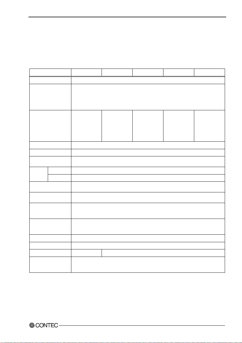
5. About Hardware
5. About Hardware
This chapter provides hardware specifications and hardware-related supplementary information.
Hardware specification
Table 5.1. Specification
Item
RAID controller ITE IT8212F, RAID 0/1/JBOD
CF slot Card Slot: Type I x 2 (Internal slot : Primary Master, External slot : Secondary Master)
CF Card Not mounting 1GB
Transfer rate 10Mbyte/sec (Read) / 9Mbyte/sec (Write)
CF Write endurance 100,000 times
Power consumption
(Max.)
Operating
condition
Relative
humidity
Impact
resistance
Impact
resistance
The number of sheets
that can be used
simultaneously
PCI bus specification 32bit, 33MHz, Universal key shapes supported *1
Dimension (mm)
Weight
Supported OS Windows XP Embedded, Windows XP professional,
*1 : This board requires power supply at +5V from an expansion slot (it does not work on a machine with a +3.3V power
supply alone).
*2 : RAID function are not supported.
(Operating)
(Storaging)
(Operating)
(Operating) 15G or less
(Operating) 10 - 57Hz/semi-amplitude 0.15mm 57 - 150Hz/2.0G
PC-RSD-PCI PC-RSD1000-PCI PC-RSD2000-PCI PC-RSD4000-PCI PC-RSD8000-PCI
Display : Card access LED (Red) x 1
Uncapable of detaching when enagized
Power supply +3.3VDC
Each slot 0.5A(Max.)
(Fix Disk spec)
One piece
standard
supprted
(Primary Mast e r )
5V 350mA, When adding CF : 5V 450mA
0 - 50°C
-25 - 85°C
10 - 90%RH (No condensation)
40 min. each in x, y, and z directions
(JIS C0040-compliant, IEC68-2-6-compliant, when using IPC-BX 630 Series)
One piece
119.91(L) x 63.41(H)
60g 70g (including CF)
Windows 2000 professional,
MS-DOS 6.2 *2, PC-DOS 2000 J7.0/V *2, PC DOS 7 *2
2GB
(Fix Disk spec)
One piece
standard
supprted
(Primary Mast e r )
4GB
(Fix Disk spec)
One piece
standard
supprted
(Primary Mast e r )
8GB
(Fix Disk spec)
One piece
standard
supprted
(Primary Mast e r )
PC-RSD Series
59
Page 65

5. About Hardware
Board Dimensions
119.91
63.41
[mm]
The external dimens io n f or (L ) [1 1 9. 91] i s the l e ng t h fr o m t he b oa r d edg e to t he ext e rior surface of the s l ot cov e r .
About Rewrite Life
The number of rewriting a CF is limited due to characteristics of the memory used in the CF. The
rewrite life can be calculated as a reference value according to the formula given below.
- Rewrite life [time] formula
Ava ilabl e capaci ty
Life [time] = N x
of CF(KB)
FStyp
x fw
N : Rewrite allowable number (100,000 times)
FStyp : Total capacity of file for rewriting (KB) (Notes : 16KB unit)
fw : Time interval for repeating the rewrite of the FStyp capacity file (Unit : Time)
Ex : 1MB file out of a 900MB space in CF is overwritten once every 5 seconds.
- Rewrite life [time] formula
Life [time] = 100,000 x
921,600
1024
5
x
= 125,000 ( = about 14 years)
3,600
(Notes : Calculation by 1MB = 1024KB)
60
PC-RSD Series
Page 66

PC-RSD1000-PCI
PC-RSD2000-PCI
PC-RSD4000-PCI
PC-RSD8000-PCI
PC-RSD-PCI
User’s Manual
CONTEC CO., LTD. June 2006 Edition
3-9-31, Himesato, Nishiyodogawa-ku, Osaka 555-0025, Japan
Japanese http://www.contec.co.jp/
English http://www.contec.com/
Chinese http://www.contec.com.cn/
No part of this document may be copied or reproduced in any form by any means without prior written
consent of CONTEC CO., LTD. [06232006]
[03022006] Management No. A-51-095
[06232006_rev3] Parts No. LYFK321
 Loading...