

Contec IPC-BX/600(PCW), IPC-BX/600(PCW)C, IPC-BX/600(PCW)CP, IPC-BX/600(PCW)C4P User Manual
Page 1

IPC Series
BOX-PC
IPC-BX/600(PCW),
IPC-BX/600(PCW)C,
IPC-BX/600(PCW)CP,
IPC-BX/600(PCW)C4P
User's Manual
CONTEC CO.,LTD.
Page 2

Copyright
Copyright 2001 CONTEC CO., LTD. ALL RIGHTS RESERVED
No part of this document may be copied or reproduced in any form
by any means without prior written consent of CONTEC CO., LTD.
CONTEC CO., LTD. makes no commitment to update or keep
current the information contained in this document.
The information in this document is subject to change without
notice.
All relevant issues have been considered in the preparation of this
document. Should you notice an omission or any questionable
item in this document, please feel free to notify
CONTEC CO., LTD.
Regardless of the foregoing statement, CONTEC assumes no
responsibility for any errors that may appear in this document nor
for results obtained by the user as a result of using this product.
Trademarks
MS, Microsoft, MS-DOS and Windows are trademarks of Microsoft
Corporation. Other brand and product names are trademarks of
their respective holder.
User’s Manual
i
Page 3

Table of Contents
Copyright...........................................................................i
Trademarks........................................................................ i
1.Introduction .................................................................. 1
Features........................................................................ 1
Compatible Operating Systems................................... 2
Limited One-Year Warranty........................................ 2
How to Obtain Service................................................. 2
Liability ........................................................................ 2
Handling Precautions.................................................. 3
About the Manual ........................................................ 5
2.Overview....................................................................... 7
Specifications.................................................................... 7
System Configuration ...................................................... 9
External Dimensions...................................................... 10
3.Hardware Setup.......................................................... 15
Before Using the BOX-PC for the First Time...............15
Hardware Setup ............................................................. 16
Removing the Top Cover and HDD Bracket............. 16
Locations and Settings of Internal Connectors and
Jumpers...................................................................... 18
Installing the Hard Disk............................................ 20
Installing the Main Memory (DIMM)....................... 21
Fastening the Power Cable........................................ 23
Installation Requirements......................................... 24
4.BIOS Setup ................................................................. 27
BIOS Setup.....................................................................27
Starting the Setup Screen ......................................... 27
Keystrokes.................................................................. 28
Main Menu ................................................................. 29
IDE Adapter Window................................................. 30
Embedded Window..................................................... 31
Advanced Window...................................................... 34
PCI Configuration Window........................................ 36
ii User’s Manual
Page 4

Cache Memory Window.............................................. 37
I/O Device Configuration Window............................. 38
Security Window......................................................... 41
Power Window............................................................42
Boot Window............................................................... 43
Exit Window................................................................44
5.Each Component Function...........................................47
Component Identification .......................................... 47
Keyboard Interface.....................................................50
Mouse Interface.......................................................... 50
Floppy Disk Interface.................................................51
Serial Port Interface...................................................53
CRT Interface ............................................................. 61
PCMCIA Slots (C, CP and C4P Models)....................62
Printer Port Interface.................................................63
RAS Functions............................................................64
Watchdog Timer.......................................................... 65
General-purpose I/O and Remote Reset....................72
S1................................................................................. 76
Reset Switch ............................................................... 76
USB Ports ................................................................... 77
Ethernet......................................................................78
Liquid Crystal Display (LCD) Interface.................... 79
IDE Interface.............................................................. 81
Expansion Slots (CP and C4P Model) ....................... 83
6.Appendix......................................................................91
Memory Map................................................................... 91
I/O Port Addresses..........................................................92
Interrupt Level List........................................................ 93
7.List of Options .............................................................95
User’s Manual
iii
Page 5

iv User’s Manual
Page 6

1. Introduction
CONTEC has been actively engaged in the development of
software that is indispensable to the optimization of systems and for
factory automation. Recent years have seen an increasing number
of users who embrace FA and LA utilizing personal computers. In
response to this trend, CONTEC has developed and marketed FA
computers (the IPC series) and a variety of interface boards.
The BOX-PC is a compact FA computer loaded with every function
needed. The following four models are available:
Basic Model
IPC-BX/M600(PCW)
Model with PCMCIA Card and Panel Link I/F
IPC-BX/M600(PCW)C
Model with PCMCIA Card, Panel Link I/F and Expansion Slot
IPC-BX/M600(PCW)CP (Expansion 2 slots)
IPC-BX/M600(PCW)C4P (Expansion 4 slots)
1. Introduction
Features
User’s Manual
- Equipped with the latest Low Power Celeron 400MHz CPU
- Fan-less operation achieved by natural air-cooling
- Ten-year long-life power supply at an ambient temperature of
40°C
- Long, reliable supply (The CPU and chip set are embedded
versions.)
- Adoption of BIOS (Phoenix Technologies, Ltd.) customized by
CONTEC to support the BIOS level
- Equipped with 100BASE-TX LAN standard
- Equipped with a secondary-IDE connector to allow an optional
external CD-ROM to be connected
- Equipped with a Panel Link I/F in addition to CRT I/F (C, CP,
C4P model)
1
Page 7

1. Introduction
Compatible Operating Systems
- Windows 2000 Professional
- Windows NT 4.0 Workstation
- Windows 98 Second Edition
Limited One-Year Warranty
CONTEC Interface boards are warranted by CONTEC CO., LTD.
to be free from defects in material and workmanship for up to one
year from the date of purchase by the original purchaser.
Repair will be free of charge only when this device is returned
freight prepaid with a copy of the original invoice and a Return
Merchandise Authorization to the distributor or the CONTEC group
office, from which it was purchased.
This warranty is not applicable for scratches or normal wear, but
only for the electronic circuitry and original boards. The warranty
is not applicable if the device has been tampered with or damaged
through abuse, mistreatment, neglect, or unreasonable use, or if the
original invoice is not included, in which case repairs will be
considered beyond the warranty policy.
How to Obtain Service
For replacement or repair, return the device freight prepaid, with a
copy of the original invoice. Please obtain a Return Merchandise
Authorization Number (RMA) from the CONTEC group office
where you purchased before returning any product.
* No product will be accepted by CONTEC group without the
RMA number.
Liability
The obligation of the warrantor is solely to repair or replace the product.
In no event will the warrantor be liable for any incidental or
consequential damages due to such defect or consequences that arise
from inexperienced usage, misuse, or malfunction of this device.
2 User’s Manual
Page 8

Handling Precautions
Take the following precautions when handling this product.
- Do not use or store the product in a location exposed to extremely
high or low temperature or susceptible to rapid temperature
changes.
Example: - Exposure to direct sun
- In the vicinity of a heat source
- Do not use the product in extremely humid or dusty locations. It
is extremely dangerous to use the product with its interior
penetrated by water or any other fluid or conductive dust. If the
product must be used in such an environment, install it on a dustproof control panel, for example.
- Avoid using or storing the device in locations subject to shock or
vibration.
- Do not use the product in the vicinity of devices that generate
strong magnetic force or noise. Such devices will cause this
device to malfunction.
- Do not use or store the product in the presence of chemicals.
- The lower center of the left face (seen from the connector's front
surface) may become hot. To avoid being burned, do not touch
that section while the product is in operation or immediately after
turning off the power. Avoid installation in a location where
people may come into contact with that section.
- To clean the BOX-PC, wipe it gently with a soft cloth dampened
with either water or mild detergent. Do not use chemicals or a
volatile solvent, such as benzene or thinner, to prevent pealing or
discoloration of the paint.
- When you need to continually operate the device using the hard
disk, be sure to run the HDD in standby mode. Running in other
than standby mode significantly shortens the product's life. (For
more information, see form titled "Precautions" that comes with
the optional product [2.5inch HDD.])
- Before installing or uninstalling an expansion board (the CP
model) or connecting or disconnecting a connector, be sure to
unplug the power cable from the wall outlet.
- CONTEC reserves the right to refuse to service a product
modified by the user.
1. Introduction
User’s Manual
3
Page 9

1. Introduction
- In the event of failure or abnormality (foul smells or excessive
heat generation), unplug the power cord immediately and contact
the sales representative you purchased the product from or the
CONTEC Information Center.
- Use an AC cable that is compatible with both the rated supply
voltage and the receptacle. (The cable provided with the
product is for 125VAC.)
- Component Life:
1. Power supply--- Estimated life is about 10 years based on
continual operation at 40°C (horizontal
installation). However, (higher) operating
temperatures will result in shorter life.
2. Battery--- The internal calendar clock and CMOS RAM
are backed by a Lithium primary battery. The
backup time at a temperature of 25°C with the
power disconnected is 10 years or more.
* Replacement of expendables is handled as a repair (there will be a
charge).
FCC PART 15 Class A Notice
NOTE
This equipment has been tested and found to comply with the limits for a Class A digital device,
pursuant to part 15 of the FCC Rules. These limits are designed to provide reasonable protection
against harmful interference when the equipment is operated in commercial environment.
This equipment generates, uses, and can radiate radio frequency energy and, if not installed and
used in accordance with the instruction manual, may cause harmful interference to radio
communications. Operation of this equipment in a residential area is likely to cause harmful
interference at his own expense.
WARNING TO USER
Change or modifications not expressly approved the manufacturer can void the user's authority to
operate this equipment.
Note!
To connect with peripherals, use a grounded, shielded cable.
4 User’s Manual
Page 10

About the Manual
This manual consists of the following chapters:
Chapter 1 Introduction
Chapter 2 Overview
Chapter 3 Hardware Setup
Chapter 4 BIOS Setup
Chapter 5 Each Component Function
Chapter 6 Appendix
Chapter 7 List of Options
1. Introduction
User’s Manual
5
Page 11

1. Introduction
6 User’s Manual
Page 12

2. Overview
PC card slot
Specifications
2. Overview
Table 2.1. Functional Specifications
CPU Low Power Mobile Celeron 400MHz, FSB100MHz(Intel)
Chip set Intel 440BX
Memory L2 Cache 128KB
Video Controller
FDD I/F
IDE HDD Primary
I/F Secondary
Serial I/F *2 RS-232C(general-purpose): 2ch (SERIAL PORT1,2) 9pin, D-SUB connector
Parallel I/F *2 Bi-directional, Centronics-compliant, 25pin D-SUB connector
LAN I/F Ethernet 100BASE-TX/10BASE-T RJ-45 connector
USB I/F 2ch (USB 1.1)
Keyboard I/F PC/AT keyboard-compatible (6pin, MINI DIN connector)
Mouse I/F PS/2-type mouse-compatible (6pin MINI DIN connector)
General-purpose I/O 3 opto-capler isolated inputs and outputs
RAS function WDT: 244.14µsec to 255sec (RESET or external output is allowed at time expiration)
Expansion board slot *2 None
RTC/CMOS Lithium backup battery life: 10 years or more
Power supply
External dimensions (mm) 262(W) x 262(D) x 55(H) 262(W) x 262(D) x 115(H)
Weight Approx. 3.3 kg Approx. 4.2 kg Approx. 5.0 kg
*1 Used with a display installed with a touch panel of Contec panel-linkage specifications.
*2 Not all functions can be used simultaneously due to a limit on the number of interrupt resources.
Main memory Max. 256MB 3.3V 144pin SO-DIMM Socket x 2
BIOS ROM 128KB E0000H to FFFFFH (Phoenix)
Video RAM
Video BIOS
CRT I/F
Panel Link I/F Not available Dedicated 20pin, half-pitch connector *1
Controller Intel 82559
Input supply
voltage
Current
consumption
Expansion board
power-supply
capacity
(Memory capacity choices: 64MB or 128MB <each uses 1 socket> or 256MB <uses 2 sockets>)
B69000(C&T)
2MB (Built into the controller)
48KB (C0000H to CBFFFF)
15pin HD-SUB connector
Equipped with a dedicated 26pin, half-pitch connector: 2 modes (Optional FDD: PC-FDD25BH)
2.5inch IDE-HDD or silicon disk can be added.
Equipped with a dedicated 40pin, half-pitch connector
(for connection of an optional CD-ROM) (right surface)
RS-232C(touch panel): 1ch (SERIAL PORT3) [inside the Panel Link connector] *1
RS-422/485(general-purpose): 1ch (SERIAL PORT4) [inside the RAS connector]
*2 None PCMCIA Type I, II x 2 or III x 1
(However, one output also serves as an external WDT output and one input also serves
as remote reset. They become available when switched.)
Remote reset: External input signal
100 to 120VAC/200 to 240VAC 50/60Hz 1.8/0.8A
42VA (Max.)
None
(Startup from ATA card not allowed)
Shared PCI/ISA slot x 2,
Installable board length:
24mm Max.
80VA(Max.) 104VA(Max.)
+5V: 2A(1A x 2 slots),
-5V: Not supplied
+12V: 0.5A, -12V: 80mA
IPC-BX/M600(PCW)C4PModel IPC-BX/M600(PCW) IPC-BX/M600(PCW)C IPC-BX/M600(PCW)CP
Shared PCI/ISA slot x 2,
PCI slot x 2,
Installable board length:
24mm Max.
+5V: 4A(1A x 4 slots),
-5V: Not supplied
+12V: 0.5A, -12V: 80mA
User’s Manual
7
Page 13

2. Overview
Table 2.2. Installation Environment Requirements
Parameter
Power supply specifications
Allowable instantaneous
power outage
Dielectric strength
Insulation resistance 50MΩ (DC500V)
Ambient specifications
Operating temperature 0 to 45ºC(HDD in use)
Storage temperature -10 to 60ºC
Humidity *1 10 to 90%RH(No condensation)
Floating dust particles Not to be excessive
Corrosive gases None
Line-noise
resistance
Vibration
resistance *2
Impact resistance *2 10G, half-sine shock for 11 ms in x, y, and z directions
Grounding Class D grounding (previous class 3 grounding)
*1 When a floppy disk is not in use.
*2 When the HDD and FDD are not in use.
Line noise AC line/2kV, Signal line/1kV (IEC1000-4-4Level 3, EN61000-4-4Level 3)
Static electricity
resistance
Sweep resistance
Fixed-vibration
resistant
Less than 20ms
One minute each for 3.0 kVAC (input-output), 2.0 kVAC (input-FG),
and 0.5 kVAC (output-FG)
0 to 50ºC(SDD in use)
5 to 45ºC(FDD in use)
Contact discharge/4kV (IEC1000-4-2Level 2, EN61000-4-2Level 2)
Atmospheric discharge/8kV (IEC1000-4-2Level 3, EN61000-4-2Level 3)
10 to 50Hz/semi-amplitude 0.15mm 50 to 500Hz/2.0G
23 min. each in x, y, and z directions
(JIS C0040-compliant, IEC68-2-6-compliant)
30 min. each in x, y, and z directions
(JIS C0040-compliant, IEC68-2-6-compliant)
(JIS C0041-compliant, IEC68-2-27-compliant)
Requirement description
8 User’s Manual
Page 14

System Configuration
Built-in
Terminal
General-purpose I/O (3)
RS-485
RAS
block
IPC-PSD-20
RS-232C
USB
2.5inch hard (silicon) disk drive
Main memory
144pin SO-DIMM
IPC-BX/M600(PCW)CP
LAN
Mouse
2. Overview
Dedicated LCD
IPC-DT/L40S(PC)T
IPC-DT/H40X(PC)T
Dedicated
LCD
Dedicated LCD cables
IPC-PL2020-020 (2m)
IPC-PL2020-050 (5m)
Option CD-ROM
CRTdisplay
Dedicated FD Drive
PC-FDD25BH
Printer
Expansion slot
(CP and C4P models)
PC-HELPER
series
PCI and ISA
half-size boards
When three or more slots are needed, select
the C4P model. To use five or more slots or
a full-size board, connect the FA-PA(PC) series.
Expansion
bus adapter
Figure 2.1. System Configuration
FA-PAC(PC)
series
Keyboard
PCMCIA card slot (C, CP and C4P models)
PCMCIA types I, II x 2, or III x 1
* Not all devices shown in the
figure can be used
simultaneously due to
a limit on the number of
interrupt resources.
User’s Manual
9
Page 15

2. Overview
External Dimensions
IPC-BX/M600(PCW)
262
170
126
56
68
302
284
262
228 1717
5.1
5
.
4-Φ 5
20
2
R
-
5
2
5
.
5
R
55
[mm]
Figure 2.2. IPC-BX/M600(PCW)
Note!
The panel link interface and PC card connector are not installed on
the IPC-BX/M600(PCW).
10 User’s Manual
Page 16

4-Φ5
2. Overview
IPC-BX/M600(PCW)C
302
284
262
262
170
126
56
68
5
.
2
R
-
5
2
R
20
23.2
5
.
5
55
228 1717
[mm]
User’s Manual
Figure 2.3. External Dimensions of the
IPC-BX/M600(PCW)C
11
Page 17

2. Overview
IPC-BX/M600(PCW)CP
262
170
126
56
68
302
284
262
228 1717
23.2
5
.
4-Φ5
20
2
R
-
5
2
5
.
5
R
115
[mm]
Figure 2.4. External Dimensions of the
IPC-BX/M600(PCW)CP
12 User’s Manual
Page 18

IPC-BX/M600(PCW)C4P
262
170
126
56
68
2. Overview
302
284
262
17
228
17
4-Φ5
5
20
User’s Manual
23.2
5
.
2
R
-
2
5
.
5
R
180
[mm]
Figure 2.5. External Dimensions of the
IPC-BX/M600(PCW)C4P
13
Page 19

2. Overview
14 User’s Manual
Page 20

3. Hardware Setup
3. Hardware Setup
Before Using the BOX-PC for the First Time
Follow the next steps to set up the BOX-PC:
STEP1 Install the hard disk and expansion main memory
(DIMM) and set jumper switches.
By referring to the information in this chapter, set the
BOX-PC.
STEP2 Connect cables.
Connect necessary external devices, such as a printer
and a CRT, to the BOX-PC using appropriate cables.
STEP3 Turn on the power.
After verifying that you have correctly followed steps
1 and 2, turn on the power. If you feel something is
wrong after turning on the power, turn off the power
immediately and check to see if the BOX-PC has
been set up correctly.
STEP4 Set up BIOS.
By referring to Chapter 4, set up BIOS. This setup
requires a keyboard and a display.
Note!
User’s Manual
* Before using the BOX-PC, be sure to execute " LOAD SETUP
DEFAULTS" to initialize the BIOS settings to their default
values.
(See Chapter 4, "Main Menu.")
If Windows is pre-installed, always connect the keyboard and mouse
before turning on the power for the first time.
15
Page 21

3. Hardware Setup
Hardware Setup
Removing the Top Cover and HDD Bracket
- Before you start, be sure that the power is turned off.
- Remove only those screws that are explained. Do not move any
other screw.
(1) Remove the top cover.
Figure 3.1. Removing the Top Cover
16 User’s Manual
Page 22

(2) Remove the hard disk bracket.
Figure 3.2. Removing the HDD Bracket
3. Hardware Setup
User’s Manual
17
Page 23

3. Hardware Setup
Locations and Settings of Internal Connectors and
Jumpers
When you remove the top cover and hard disk bracket, the
connectors, jumpers, and switches are laid out as shown in the
figure below:
3
3
12
JP2
JP2
1 2
(B)
(A)
CN15
87
654321
(B)
S1
ON
OFF
M2
JP1
(B)
1 2 3
* The position of the jumpers mounted changes with kinds (A, B) of substrate.
JP1 is not mounted by A type.
(A)
87
654321
S1
ON
OFF
(A)
(B)
1 2 3
JP4
JP4
123
Figure 3.3. Locations and Settings of Jumpers, Connectors,
and Switches inside the Top Cover
18 User’s Manual
Page 24

3. Hardware Setup
Table 3.1. Jumper List
Function Factory setting RemarksNo.
JP1 - Selects BUS clock scale. 1-2 shorted --- Settings other than 1-2 are not allowed.
JP2 - Clear CMOS. 1-2 shorted --- Short 2-3 to clear CMOS.
JP4 - Sets RS-485 termination. 2-3 shorted 55
- Sets destination where BIOS
setup details will be saved.
S1
- Sets up LCD. 2, 5, 6, and 7 ON 76
1, 3, 4, and 8 OFF 45
Reference
page
Table 3.2. Internal Connector List
Connector Reference page
CN15 Primary IDE connector (44pin, pin header) 81
M2 Expansion memory set (3.3V, 144pin SO-DIMM) 22
Function
User’s Manual
19
Page 25

3. Hardware Setup
Installing the Hard Disk
(1) Connect the provided HDD cable to the hard disk (silicon
disk).
Note!
Connect the HDD cable in alignment with pins from the left
end of the connector on the HDD side.
Four master/slave setting pins are left unconnected on the
right side. Be aware that connecting the power with the
connector misaligned will damage the cable.
(2) By threading the cable through the hole on the base of the hard
disk bracket, fasten the disk to its bracket using four screws.
- Use the upper screw holes of the hard disk bracket.
- Fasten the disk using the outer or inner hole depending on the
model you are using. (The figure below shows an example
that uses the inner screw hole.)
(3) Connect the HDD cable to CN15 on the unit and fasten the
hard disk bracket to the unit using four screws.
20 User’s Manual
Page 26

(4) Close the top cover and secure it with screws.
3. Hardware Setup
Figure 3.4. Installing the Hard Disk
Installing the Main Memory (DIMM)
Compatible DIMM Types
Obtain the following special option products.
- Package type : 144-pin, small outline DIMM
- Specifications : 3.3V, PC100/CL2
- Capacity : 64MB / 128MB
- Type : SDRAM
- Optional memories * : 64MB : PC-MSD64-144H
* Operation is not guaranteed if memory parts other than CONTEC
option products are used.
Main Memory (DIMM) Installation Procedure
Follow the next steps to fit the memory into the DIMM socket:
User’s Manual
128MB : PC-MSD128-144H
21
Page 27

3. Hardware Setup
(1) Insert the DIMM into its socket with the notch positioned on the right side.
(2) Press in the direction indicated by the arrow. You hear a click as the memory fits
Figure 3.5. Installing the DIMM
DIMM Disconnection Procedure
(See the note.)
into the socket.
DIMM socket
DIMM
DIMM
socket
1
Notch
Note: As shown in the Figure, insert
the DIMM in angle.
Inserting as indicated with "x"
may damage socket pins.
Open the levers on both sides slightly to the left and right.
You should be able to remove the DIMM.
30°~45°
Figure 3.6. Uninstalling the DIMM
22 User’s Manual
Page 28

Fastening the Power Cable
Removing the Screw on the Metal Brace to Keep the AC Cord
in Place
In order to install the metal brace, temporarily remove the machine
screw on the front left end.
Remove this screw .
Figure 3.7. Removing the Screw
Installing the AC Cord Metal Brace and the Clamp
Insert the AC cord all the way into the inlet. Fasten the AC cord
metal brace using the screw you removed earlier. Attach the
clamp to an appropriate location on the metal brace to clamp the
cord. The “AC cord metal brace” is attached to the main case.
3. Hardware Setup
Metal brace to keep
the AC cord in place
Clamp
Figure 3.8. Installing the Metal Figure 3.9. AC Cord
Brace and the Clamp in Clamped State
User’s Manual
23
Page 29

3. Hardware Setup
Installation Requirements
The BOX-PC can be installed in any orientation (1) through (5).
Avoid orientation (6) since it might not adequately dissipate heat.
Similarly, to maintain the ambient temperature within the range
specified in the specifications, ensure a clearance between the unit
and surrounding equipment of at least 100mm for the top and rear
and 50mm for the bottom and sides.
Installation Orientation
(1)
Floor
(2)
Wall
(6)
Wall
Connectors
Ceiling
Figure 3.10. Installation Orientation
(5)(4)(3)
Connectors
Wall
Wall
24 User’s Manual
Page 30

3. Hardware Setup
Distances between the BOX-PC and Its Vicinity
50mm or more (side)
Connectors
50mm or more (side)
100mm or more (above)
50mm or more (back)
Figure 3.11. Distances between the BOX-PC and Its Vicinity
User’s Manual
25
Page 31

3. Hardware Setup
26 User’s Manual
Page 32

4. BIOS Setup
BIOS Setup
BIOS setup sets various settings during startup. When using the
system for the first time, be sure to run BIOS setup. Once set up,
the specified details will be backed up.
Starting the Setup Screen
When you turn on the system, it displays "Press <F2> to enter
SETUP" if the system is normal. Press the <F2> key on the
keyboard.
Phoenix BIOS 4.0 Release 6.0
Copyright 1985-2000 Phoenix Technologies Ltd.
All Rights Reserved
Copyright 2000, CONTEC Co., Ltd.
BX/M600(PCW), Px/x600(PCW) sereies BIOS ver.1.00.
CPU = Intel(R) Mobile Celeron(TM) processer 400MHz
640K System RAM Passed
63M Extended RAM Passed
128K Cache SRAM Passed
System BIOS shadowed
Video BIOS shadowed
UMB Upper limit segment address: E7BB
4. BIOS Setup
User’s Manual
Press <F2> to enter SETUP
Figure 4.1. Initial Screen
27
Page 33

4. BIOS Setup
Keystrokes
The following is a list of major key functions you can use during
BIOS setup:
Table 4.1. Key Function List
Key to press
→, ← Moves the main menu.
↑ , ↓ Moves between items to be set.
<Tab>
<Shift>+<Tab>
<Spacebar>
+
<Enter>
<Esc>
<F9>
<F10>
Moves within items to be set.
Moves in the direction opposite to <Tab>.
Changes details to be set.
Functions the same as <Spacebar>.
Changes in the direction opposite to the + key.
Opens submenus.
Moves to the Exit window.
Resets all to defaults.
Saves set values and exits setup.
Function
28 User’s Manual
Page 34

Main Menu
4. BIOS Setup
Main Embedded Advanced Security Power Boot Exit
System Time: [09:21:27]
System Date: [01/01/1993]
Legacy Diskette A: [1.44/1.25 MB 31/2"]
Legacy Diskette B: [Disabled]
Floppy Drive Swap: [Disabled]
3 MODE floppy: [Disabled]
Primary Master [4312MB]
Primary Slave [None]
Secondary Master [None]
Secondary Slave [None]
System Memory: 640 KB
Extended Memory: 64512 KB
↓
F1 Help
Esc Exit
↓
Select Item -/+ Change Values F9 Setup Defaults
←→
Select Menu Enter Select Sub-Menu F10 Save and Exit
PhoenixBIOS Setup Utility
Item Specific Help
Figure 4.2. Main Window (Factory Settings)
System Time : Sets the time on the equipment calendar
clock.
System date : Sets the date on the equipment calendar
clock.
Diskette A : Specify the type of FDD to be used as
drive A. If you are not using the FDD,
set to "Disabled." Do not set to
"2.88MB" since it is not supported.
User’s Manual
Diskette B : Connection not allowed. Set to
"Disabled."
Floppy Drive Swap : Set to "Disabled."
3 Mode floppy : Set to "Disabled."
29
Page 35

4. BIOS Setup
Primary Master : Set the type of HDD to be used as the
Primary Slave : Connection not allowed. Set to
Secondary Master : Normally, connection is not allowed.
Secondary Slave : Connection not allowed. Set to
IDE Adapter Window
first drive.
If you are not using the HDD, set to
"None."
Select "Auto" setup to make setting
easier.
"None."
Set only when you set the PCMCIA
connector's ATA disk to secondary or
when you connect an external CDROM.
"None."
Main
Primary Master [4312MB]
Type: [Auto]
Cylinders: [ 8912]
Heads: [ 15]
Sectors: [63]
Maximum Capacity: 4312MB
Multi-Sector Transfers: [16 Sectors]
LBA Mode Control: [Enabled]
32 Bit I/O: [Disabled]
Transfer Mode: [Fast PIO 4]
Ultra DMA Mode: [Mode 2]
F1 Help ↓Select Item -/+ Change Values F9 Setup Defaults
Esc Exit
↓
←→
Select Menu Enter Select Sub-Menu F10 Save and Exit
PhoenixBIOS Setup Utility
Item Specific Help
User = you enter
parameters of hard-disk
drive installed at this
connection.
Auto = autotypes
hard-disk drive
installed here.
1-39 = you select
pre-determined type of
hard-disk drive
installed here.
CD-ROM = a CD-ROM drive
is installed here.
ATAPI Removable =
removable disk drive is
installed here.
Figure 4.3. IDE Adapter Window (Factory Settings)
Type : Set to "Auto" to use the primary master.
Otherwise set to "None."
30 User’s Manual
Page 36

Embedded Window
4. BIOS Setup
Main Embedded Advanced Security Power Boot Exit
Keyboard Error Disp.: [Disabled]
RTC check: [Enabled]
Memory Safemode: [Enabled]
System Clock(CPU/PCI MHz): [100.3/33.43]
Spread Spectrum Modulation: [Enabled]
CRT/FPD: [AUTO Select]
DOC Address: [Disabled]
Watch-dog Timer: [Disabled]
PCIC Irq Mode: [Continous]
Push switch function: [Reset]
F1 Help ↓Select Item -/+ Change Values F9 Setup Defaults
Esc Exit
↓
←→
Select Menu Enter Select Sub-Menu F10 Save and Exit
PhoenixBIOS Setup Utility
Item Specific Help
Restrain error display
of no keyboard.
Figure 4.4. Embedded Window (Factory Settings)
Keyboard Error Disp. : Specify whether or not to display errors
when no keyboard is used.
RTC check : Specify whether or not to display time
errors when the RTC backup battery is
depleted.
Memory Safemode : Set to Enable.
User’s Manual
System Clock(CPU/PCI MHz) :
Set the system clock. Normally, set to
"100.3/33.43." However if you are
concerned with heat dissipation, for
example, set to "66.8/33.40."
Spread Spectrum Modulation : Set to Enable.
31
Page 37

4. BIOS Setup
CRT/FPD : Specify the display type.
Choose from "CRT Only," "AUTO
Select," "SW Select," "VGA TFT,"
"SVGA TFT," and "XGA TFT." When
you are using only a CRT, select "CRT."
For others, set to "AUTO Select."
AUTO Select:
It automatically recognizes the type of
FPD with COM-port signals on the
FPD signal when PC startups. In case
of not connecting FPD to BOX-PC or
not turning on FPD, it will be CRTMode. Also FPD will not be displayed.
CRT Only:
Select this option to use only a CRT.
SW Select:
Select this option to follow the S1
settings.
SVGA TFT:
800×600 TFT(IPC-DT/L40S(PC)T)
only. This option overrides the SW
settings.
XGA TFT:
1024×768 TFT(IPC-DT/H40X(PC)T)
only. This option overrides the SW
settings.
VGA TFT:
Currently, there is no panel link display
available that corresponds to the 640 x
480 TFT.
DOC Address : Set to "Disabled".
Watch-dog Timer: Specify the output status of the RAS
connector (PO2/WDT) signal during
BIOS startup.
Disable:
Sets the RAS connector's
32 User’s Manual
Page 38

PO2/WDT(12) signal to PO2 (generalpurpose output).
Enable:
Sets the RAS connector's
PO2/WDT(12) signal to Alarm Out.
Alarm out status at BIOS startup should
be set with the submenu.
PCIC Irq Mode : Set to "Continous".
Push switch function : Set to "Reset".
4. BIOS Setup
User’s Manual
33
Page 39

4. BIOS Setup
Advanced Window
Main Embedded Advanced Security Power Boot Exit
Installed O/S: [Other]
Enabled ACPI: [No]
Reset Configuration Data: [No]
PCI Configuration
Cache Memory
Legacy USB Support: [Disabled]
I/O Device Configuration
Large Disk Access Mode: [DOS]
Local Bus IDE adapter: [Both]
PCMCIA ATA DISK [Disabled]
F1 Help ↓Select Item -/+ Change Values F9 Setup Defaults
Esc Exit
↓
Select Menu Enter Select
←→
PhoenixBIOS Setup Utility
Item Specific Help
Select the operating
system installed
on your system which
you will use most
commonly .
Note: An incorrect
setting can cause
some operating
systems to display
unexpected behavior.
Sub-Menu F10 Save and Exit
Figure 4.5. Advanced Window (Factory Settings)
Installed OS : Normally, set to "Other."
Enabled ACPI : Set to "No".
Reset Configuration Data: Resets the resources assigned to the PCI
and PnP devices.
Before installing the OS, set “Yes” to
reset the configuration. The setting
automatically returns to “No” after
rebooting.
PCI Configuration : Allows resources to be reserved for
legacy devices.
Cache Memory : Specify whether to enable or disable
cache memory.
Legacy USB Support : Set to "Disabled."
I/O Device Configuration: Set COM/LPT.
Large Disk Access Mode : Normally, set to "DOS."
Local Bus IDE adapter * : Sets the on-board IDE controller.
34 User’s Manual
Page 40

4. BIOS Setup
PCMCIA ATA DISK * : Specify when the ATA card needs to be
booted. Ensure that the setting does
not collide with a local IDE controller.
ATA card boot cannot be used in
Windows, for example.
* As to the local bus IDE adapter and the PCMCIA ATA DISK, a
combined total of two units can be used at maximum.
User’s Manual
35
Page 41

4. BIOS Setup
PCI Configuration Window
Main Embedded Advanced Security Power Boot Exit
PCI Configuration
PCI/PNP ISA UMB Region Exclusion
PCI/PNP ISA IRQ Resource Exclusion
PCI/PNP ISA DMA Resource Exclusion
F1 Help ↓Select Item -/+ Change Values F9 Setup Defaults
Esc Exit
↓
←→
Select Menu Enter Select Sub-Menu F10 Save and Exit
PhoenixBIOS Setup Utility
Item Specific Help
Reserve specific upper
memory blocks for use
by legacy ISA devices
Figure 4.6. PCI Configuration Window
PCI/PNP ISA UMB Region Exclusion
: When using a board installed with a
ROM for ISA, set the address that
board will be using to Reserved. *
(Unless a problem occurs, this setting
does not need to be modified.)
PCI/PNP ISA IRQ Resource Exclusion
: Set the IRQ which ISA will be using to
Reserved. Set the IRQ which you have
specified manually by selecting Enable
in the I/O Device Configuration
window to Available. In addition, set
one IRQ which a PCI device will be
using to Available. (See the Note
below)
36 User’s Manual
Page 42

PCI/PNP ISA DMA Resource Exclusion
* Do not set all of these resources to “Reserved”, or BIOS Setup
will be unable to be invoked. If they are all set so, the CMOS
RAM must be cleared (by setting the JP2).
Note!
As IRQ11 is reserved for PCI devices, this setting should always be
fixed to “Available”.
Do not use this interrupt(IRQ11) for ISA devices or internal
peripherals (such as the COM ports).
Cache Memory Window
4. BIOS Setup
: When using a DMA board for ISA, set
the DMA channel that board will be
using to Reserved.
Main Embedded Advanced Security Power Boot Exit
Memory Cache: [Enabled]
Cache System BIOS area: [Write Protect]
Cache Video BIOS area: [Write Protect]
Cache Base 0-512k: [Write Back]
Cache Base 512k-640k: [Write Back]
Cache Extended Memory Area: [Write Back]
Cache A000 - AFFF: [Disabled]
Cache B000 - BFFF: [Disabled]
Cache C800 - CBFF: [Disabled]
Cache CC00 - CFFF: [Disabled]
Cache D000 - D3FF: [Disabled]
Cache D400 - D7FF: [Disabled]
Cache D800 - DBFF: [Disabled]
Cache DC00 - DFFF: [Disabled]
Cache E000 - E3FF: [Disabled]
F1 Help ↓Select Item -/+ Change Values F9 Setup Defaults
Esc Exit
↓
←→
Select Menu Enter Select Sub-Menu F10 Save and Exit
PhoenixBIOS Setup Utility
Cache Memory
Item Specific Help
Sets the state of the
memory cache.
Figure 4.7. Cache Memory Window (Factory Settings)
Keep the factory settings.
User’s Manual
37
Page 43

4. BIOS Setup
I/O Device Configuration Window
Main Embedded Advanced Security Power Boot Exit
I/O Device Configulation
Serial port A: [Enabled]
Base I/O address: [3F8]
Interrupt: [IRQ 4]
Serial port B: [Enabled]
Base I/O address: [2F8]
Interrupt [IRQ 3]
Serial port C: [Enabled]
Base I/O address: [3E8]
Interrupt: [IRQ 7]
Serial port D: [Disabled]
Parallel port: [Disabled]
F1 Help ↓Select Item -/+ Change Values F9 Setup Defaults
Esc Exit
↓
←→
Select Menu Enter Select Sub-Menu F10 Save and Exit
PhoenixBIOS Setup Utility
Item Specific Help
Configure serial port A
using options:
[Disabled]
No configuration
[Enabled]
User configuration
[Auto]
BIOS or OS chooses
configuration
(OS Controlled)
Displayed when
controlled by OS
Figure 4.8. I/O Device Configuration Window (Factory
Settings)
Serial port A : This setting is for SERIAL1 on the
equipment connector plane.
Serial port B : This setting is for SERIAL2 on the
equipment connector plane.
Serial port C : This setting is for serial communication
of the touch-panel port.
Serial port D : This setting is for RS-422/485 of the
RAS connector on the equipment
connector plane.
When the port is set to "Enable," it
defaults to the following:
Base I/O address [2E8]
Interrupt [IRQ5]
38 User’s Manual
Page 44

4. BIOS Setup
Parallel port : This setting is for PRINTER on the
equipment connector plane.
When the port is set to "Enable," it
defaults to the following:
Mode [ECP]
Base I/O address [378]
Interrupt [IRQ7]
DMA channel [DMA3]
Items to be set Enable:
Manually set the base I/O address and
IRQ. The IRQ you set here must be set
to Available in the PCI Configuration
window. (See the Note below).
Auto:
Automatically set by the BIOS. Enabled
once the BIOS is started.
OS Controlled:
Automatically set by the OS. Remains
disabled until the PnP OS is started.
Mode*:
Set to parallel port's operating mode.
User’s Manual
DMA channel*:
This is the DMA channel setting used
when ECP is selected during parallelport mode setting.
* A menu exclusive to the parallel port.
39
Page 45

4. BIOS Setup
Note!
If the following message appears on booting when serial port D or
the parallel port are set to “Enable”, this indicates a resource
(IRQ) conflict or similar BIOS problem.
Error
0615: Com D configuration changed
In this case, enter the setup menu again and change the IRQ from
“Reserved” to “Available” or modify the settings if an interrupt
conflict occurs.
* Serial port D: [Enable]← An asterisk (*) is displayed
Base I/O address: [2E8]
Interrupt: [IRQ5]
Set to “Available” in the PCI
→
Configuration window.
PCI/PnP ISA Reserve Exclusion
* IRQ5: [Reserved] → Change to [Available].
40 User’s Manual
Page 46

Security Window
4. BIOS Setup
Main Embedded Advanced Security Power Boot Exit
Set User Password [Enter]
Set Supervisor Password [Enter]
Supervisor Password Is: Clear
User Password Is: Clear
Password on boot: [Disabled]
Clear All Passwords [Enter]
F1 Help ↓Select Item -/+ Change Values F9 Setup Defaults
Esc Exit
↓
←→
Select Menu Enter Select Sub-Menu F10 Save and Exit
PhoenixBIOS Setup Utility
Item Specific Help
Supervisor Password
controls access to the
setup utility.
Figure 4.9. Security Window (Factory Settings)
Set Supervisor Password : Specify whether or not to require a
password during setup. If a password
is set, "Supervisor Password is" is
enabled. Supervisor mode allows all
settings to be set.
Set User Password : Specify whether or not to require a
password during setup. If a password
is set, "User Password is" is enabled.
User mode allows only the date and
time to be set.
Note!
User’s Manual
Password on boot : Specify whether or not to require a
password when booting.
Clear All Password : Both passwords can be erased by
Supervisor.
Once a password is registered, even the password function itself
cannot be cancelled without the password. Passwords should be
handled with great care.
41
Page 47

4. BIOS Setup
Power Window
Main Embedded Advanced Security Power Boot Exit
Power Savings: [Disabled]
Standby Timeout: [Off]
Auto Suspend Timeout: [Off]
IDE Drive 0 Monitoring: [Disabled]
IDE Drive 1 Monitoring: [Disabled]
IDE Drive 2 Monitoring: [Disabled]
IDE Drive 3 Monitoring: [Disabled]
PCI Bus Monitoring: [Disabled]
F1 Help ↓Select Item -/+ Change Values F9 Setup Defaults
Esc Exit
↓
←→
Select Menu Enter Select Sub-Menu F10 Save and Exit
PhoenixBIOS Setup Utility
Item Specific Help
Maximum Power Savings
conserves the greatest
amount of system power.
Maximum Performance
conserves power but
allows greatest system
performance. To alter
these settings, choose
Custumized. To turn off
power management.
choose Disabled.
Figure 4.10. Power Window ( Factory Settings)
Power Savings : Specify whether or no to use power-
saving mode. Choose from "Off",
"Customize," "Maximum
Performance," and "Maximum Power
Savings."
Standby Timeout : Specify the length of time from the idle
state through entry into standby mode.
Standby mode turns off the power to
peripherals including the screen.
Auto Suspend Timeout : Specify the time of transition from
standby mode to suspend mode.
IDE DRIVE 0 Monitoring :
IDE DRIVE 1 Monitoring : Specify whether or not to use
IDE DRIVE 2 Monitoring : a device as an idle timer reset
IDE DRIVE 3 Monitoring : event.
PCI Bus Monitoring :
42 User’s Manual
Page 48

Boot Window
4. BIOS Setup
Main Embedded Advanced Security Power Boot Exit
*Removable Devices
*Hard Drive
Bootable Add-in Cards
WDC AC14300R-(PM)
ATAPI CD-ROM Drive
Network Boot
F1 Help ↓Select Item -/+ Change Values F9 Setup Defaults
Esc Exit
↓
←→
Select Menu Enter Select Sub-Menu F10 Save and Exit
PhoenixBIOS Setup Utility
Item Specific Help
Keys used to view or
configure devices
<Enter> expands or
collapses devices with
a - or
<Ctrl-Enter> expand
all
<Shift - 1> enables or
disables a device
<-> and < > moves the
device up or down.
<n> May move removable
device between Hard
Disk or Removable Disk
<d> Remove a device
That os not installed.
Figure 4.11. Boot Window (Factory Settings)
Specify the order in which the system to be booted is checked.
Using the <+> or <-> key, rearrange the selected items.
The following devices can be specified as boot devices:
Removable Devices : Removable devices such as the floppy
disk and ATA card.
User’s Manual
Hard Drive : Devices that are not removable, such as
the hard disk drive and silicon disk
drive.
ATAPI CD-ROM Drive : Optional CD-ROM drive (IDE
connection)
Network Boot : This item is not available.
The items are displayed on the menu in priority order.
43
Page 49

4. BIOS Setup
Exit Window
Main Embedded Advanced Security Power Boot Exit
Exit Saving Changes
Exit Discarding Charges
Load Setup Defaults
Discard Changes
Saves Changes
F1 Help ↓Select Item -/+ Change Values F9 Setup Defaults
Esc Exit
↓
←→
Select Menu Enter Select Sub-Menu F10 Save and Exit
PhoenixBIOS Setup Utility
Item Specific Help
Exit System Setup and
save your changes to
CMOS.
Figure 4.12. Exit Window
Exit Saving Changes : Saves values that have been modified
on the setup screen in CMOS
(EEPROM *1) and restarts the system.
Exit Discarding Changes : Restarts the system using the previous
values without saving modified values
in CMOS (EEPROM *1).
Load Setup Defaults : Sets default values that are in the
possession of BIOS.
Discard Changes : Loads values that are currently in the
possession of CMOS(EEPROM *1).
44 User’s Manual
Page 50

4. BIOS Setup
S
1
Save Changes : Saves values that have been modified
on the setup screen in CMOS
(EEPROM *1).
*1 S1's bit 2 allows you to specify the
location where setup details will be
saved and loaded.
Normally, set to ON (use CMOS).
ON: Uses the CMOS as the location to
save and load setup details.
(factory settings)
OFF: Uses the EEPROM as the
location to save and load setup
details.
ON
1 2 3 4 5 6 7 8
Figure 4.13. S1 Factory Setting
User’s Manual
45
Page 51

4. BIOS Setup
46 User’s Manual
Page 52

5. Each Component Function
LCD and PCMCIA connectors
Component Identification
IPC-BX/M600(PCW)
5. Each Component Function
Top cover
POWER SW
AC inlet
SERIAL2
SERIAL1 RESETUSB FD
IPC-BX/M600(PCW)C
Top cover
POWER SW
AC inlet
SERIAL2
SERIAL1 RESETUSB FD
IPC-BX/M600(PCW)CP
Top cover
RAS
SERIAL2
POWER SW
LCD
not mounted.
RAS
VGA
RAS
VGA
PCMCIA slots 1 and 2
PRINTER
LCD
PRINTER
UTP(Ethernet)
PCMCIA
UTP(Ethernet)
Expansion slot (PCI/ISA) x 2
HDD LED
MOUSE
Keyboard
POWER LED
HDD LED
MOUSE
Keyboard
POWER LED
HDD LED
MOUSE
Keyboard
AC inlet
SERIAL1 RESETUSB FD
VGA
PRINTER
UTP(Ethernet)
User’s Manual
POWER LED
47
Page 53

5. Each Component Function
IPC-BX/M600(PCW)C4P
Top cover
LCD
PCMCIA slots 1 and 2
Expansion slot(PCI/ISA) x 2 and PCI x 2
RAS
SERIAL2
POWER SW
AC inlet
SERIAL1 RESETUSB FD
VGA
PRINTER
UTP(Ethernet)
Side view
IPC-BX/M600(PCW), IPC-BX/M600(PCW)CP
IPC-BX/M600(PCW)C IPC-BX/M600(PCW)C4P
Secondary IDE Connector
Figure 5.1. Component Identification
HDD LED
MOUSE
Keyboard
POWER LED
48 User’s Manual
Page 54

5. Each Component Function
Table 5.1. Component Functions
FunctionComponent
KB Keyboard connector (MINI-DIN, 6pin)
MOUSE PS/2 mouse connector (MINI-DIN, 6pin)
FD Floppy disk drive connector (26pin, half-pitch connector)
SERIAL1 Serial port 1 connector (9pin, male D-SUB)
SERIAL2 Serial port 2 connector (9pin, male D-SUB)
VGA CRT connector (15pin, female HD-SUB)
PCMCIA PCMCIA card slot <C, CP and C4P models>
PRINTER Parallel port connector (25pin, female D-SUB)
RAS RAS function and RS-485 connector (15pin, female D-SUB)
RESET Hard reset push button
USB USB port connector
UTP Ethernet connector
LCD LCD connector (20pin, half-pitch connector) <C, CP and C4P models>
Expansion slots
POWER LED Power ON indicator
HDD LED Internal hard disk access lamp
POWER SW Power switch
AC INLET AC power supply input connector
SECONDARY IDE Secondary IDE connector (dedicated 40pin half-pitch connector)
PCI/ISA expansion board slot x 2 <CP model>
PCI/ISA expansion board slot x 2, PCI expansion board slot x 1 <C4P model>
User’s Manual
49
Page 55

5. Each Component Function
Keyboard Interface
The BOX-PC is equipped with a keyboard connector named KB
(MINI-DIN 6P).
Table 5.2. Keyboard Connector
Connector type Equivalent to the MD-DS12300-14S-14 (JST)
Pin No.
1
2
3
4
6
4
2
Signal
+KBD DATA
N.C.
GND
+5.0V DC
1
Pin No.
5
6
SHIELD
---
5
3
Signal
+KBD CLK
N.C.
GND
Mouse Interface
The BOX-PC is equipped with a mouse connector named MOUSE
(MINI-DIN 6P).
Table 5.3. Mouse Connector
Connector type Equivalent to the MD-DS12300-14S-14 (JST)
6
4
5
3
2
Pin No.
1
2
3
4
Signal
+MOUSE DATA
N.C.
GND
+5.0V DC
1
Pin No.
5
6
SHIELD
---
Signal
+MOUSE CLK
N.C.
GND
50 User’s Manual
Page 56

5. Each Component Function
Floppy Disk Interface
The BOX-PC is equipped with a FD controller to allow one FD
drive to be connected to the FD connector named FD on the front
end.
Use the FD drive that is available as a dedicated option.
Table 5.4. FD Connector
Connector in use
Pin No.
1
3
5
7
9
11
13
15
17
19
21
23
25
26-socket, half-pitch connector, Equivalent to the DX10G1M-26SE
25 1
226
Signal
HDSEL
RDATA
GND
GND
GND
WDATA
DENSEL
DENSEL
N.C.
DRV_SEL
+5V
+5V
INDEX
Direction
Output
Input
-----
-----
----Output
Output
Output
----Output
-----
-----
Input
Pin No.
2
4
6
8
10
12
14
16
18
20
22
24
26
Signal
WRTPRT
TRK0
GND
WGATE
GND
GND
STEP
DIR
MTR_ON
N.C.
DSKCHG
N.C.
+5V
Direction
Input
Input
-----
Output
-----
----Output
Output
Output
-----
Input
-----
-----
User’s Manual
51
Page 57

5. Each Component Function
Compatible Connector on the Cable Side
Plug connector : AMP, P/N
Shield case kit : AMP, P/N 1756774-4
or
Plug connector : 3M, P/N
Shell : 3M, P/N 10326-3210-000
or
Plug connector : 3M, P/N 10126-3000VE
Shell system : 3M, P/N 10326-52F0-008 (Non-shield shell kit)
Cable Length
Use within a maximum cable length of 60cm.
1756774-4 (AWG#28 for pressure welding)
10126-6000EL (AWG#28 for pressure welding)
(AWG#24-#30 provided with solder)
52 User’s Manual
Page 58

5. Each Component Function
Serial Port Interface
RS-232C Ports (Serial ports A and B)
The BOX-PC is equipped with two RS-232C-compliant serial port
connectors (SERIAL1: Serial port A and SERIAL2: Serial port B).
Each port can be set independently to COM1-COM4 or "not in use"
by BIOS setup (the identical COM number cannot be specified).
Table 5.5. SERIAL 1 and 2 I/O Addresses and Interrupts
COM I/O Address Interrupt
1 3F8h-3FFh
2 2F8h-2FFh
3 3E8h-3EFh
4 2E8h-2EFh
The BIOS defaults to the following factory settings:
Serial port A : COM1(3F8h-3FFh),IRQ4
Serial port B : COM2(2F8h-2FFh),IRQ3
Table 5.6. Serial Port Connector
Connector used on the unit 9-socket D-SUB (MALE)
1 5
IRQ 3
IRQ 4
IRQ 5
IRQ 7
IRQ 9
IRQ 10
IRQ 11
IRQ 15
No.4-40UNC
Inch thread
User’s Manual
9
6
Pin No.
Signal
1
CD
2
RD
3
TD
4
DTR
5
GND
6
DSR
7
RTS
8
CTS
9
RI
Meaning
Carrier detect
Received data
Transmitted data
Data terminal ready
Signal ground
Data set ready
Request to send
Clear to send
Ring indicator
Direction
Input
Input
Output
Output
-----
Input
Output
Input
Input
53
Page 59

5. Each Component Function
RS-422/485 Port (Serial port D)
The BOX-PC is equipped with a serial port for one channel inside
the RAS connector. BIOS setup (see Chapter 4) allows I/O
addresses, interrupts and "not in use" to be set. (The port cannot
be set to the same I/O address or interrupt as of another device.)
Table 5.7. Serial Port D I/O Addresses and Interrupts
COM I/O Address Interrupt
1 3F8h-3FFh
2 2F8h-2FFh
3 3E8h-3EFh
4 2E8h-2EFh
The BIOS defaults to the following factory settings:
Serial port D : Disable
RS-422/RS-485 Specifications
- Transmission method : RS-422/RS-485-compliant,
IRQ 3
IRQ 4
IRQ 5
IRQ 7
IRQ 9
IRQ 10
IRQ 11
IRQ 15
asynchronous, serial transmission, half
duplex/full duplex
- Baud rate : 19,200-50bps (programmable)
- Signal extension distance: 1.2km Max.
Output Connector When RS-422/RS-485 Is in Use
Table 5.8. Output Connector when the RS-422/RS-485 Is in
Use (RAS Connector)
Pin No. Signal
2 TX + Transmitted data +
10 TX - Transmitted data -
3 RX + Received data +
11 RX - Received data -
Meaning
For more information on the RAS connector see Table 5.16., "RAS
connector."
54 User’s Manual
Page 60

5. Each Component Function
JP4
JP4
Terminal Resistor when RS-485 is in Use
Set with JP4 inside the top cover. The factory setting is " terminal
resistor not available."
123
2 and 3 shorted
Receiver terminal
resistor not available
Receiver terminal
123
1 and 2 shorted
resistor available
Figure 5.2. Terminal Resistor Settings
Control of Transmitted Data in Half-Duplex Mode
In half-duplex mode, the transmission buffer needs to be controlled
in order to prevent collision of transmitted data. The BOX-PC
uses RTS and controls the buffer with modem control register's bit 1.
Transmission and reception gate control by the register setting of
port address 4006h and 4007h is allowed only for the RS-422/485
(Serial port D). For more information see section, "Generalpurpose I/O and Remote Reset" in Chapter 5.
Modem control register
(Set I/O address +4H) bit 1: 0 … RTS is High.
(Disable transmission)
1 … RTS is Low.
(Enable transmission)
User’s Manual
55
Page 61

5. Each Component Function
I/O Addresses and Instructions
The I/O addresses and instructions of COM1 are shown next.
Table 5.9. I/O Addresses
I/O address DLAB Read/Write
0 W Transmitter holding register THR
03F8H R Receive buffer register RBR
1 W Divisor latch register DLL
03F9H
03FAH X R Interrupt ID register IIR
03FBH X W Line control register LCR
03FCH X W Modem control register MCR
03FDH X R Line status register LSR
03FEH X R Modem status register MSR
03FFH X R/W Scratch register SCR
DLAB (Divisor Latch Access Bit) : The value in bit 7 of the line control register
1 W Divisor latch register DLM
0 W Interrupt enable register IER
Register
56 User’s Manual
Page 62

5. Each Component Function
Table 5.10. Function of Each Register < 1 / 4 >
I/O address Description
03F8H
03F8H
03F8H
03F9H
03F9H
THR: Transmitter Holding Register [DLAB=0]
D7 D6 D5 D4 D3 D2 D1 D0
bit7
MSB
Register dedicated to write transmitted data to
RBR: Reciever Buffer Register [DLAB=O]
D7 D6 D5 D4 D3 D2 D1 D0
bit7
MSB
Register dedicated to read received data from
DLL: Divisor Latch (LSB) [DLAB=1]
D7 D6 D5 D4 D3 D2 D1 D0
bit7
MSB
Baud rate setting register (LSB)
DLH: Divisor Latch (MSB) [DLAB=1]
D7 D6 D5 D4 D3 D2 D1 D0
bit7
MSB
Baud rate setting register (MSB)
IER: Interrupt Enable Register [DLAB=0]
D7 D6 D5 D4 D3 D2 D1 D0
0
0 0 0 EMS ELSI
ETHREI
Receiver line status
Interrupt enable
Modem status interrupt enable
[Always used at 0.]
bit0
LSB
bit0
LSB
bit0
LSB
bit0
LSB
ERDAI
Received data
Interrupt enable
Received data register empty
Interrupt enable
User’s Manual
1: Enable interrupt
0: Disable interrupt
57
Page 63

5. Each Component Function
Table 5.10. Function of Each Register < 2 / 4 >
I/O address Description
03FAH
IIR : Interrupt Identification Register
bit20bit10bit01Priority Description
1 1 0
1 0 0
0 1 0
0 0 0
D7 D6 D5 D4 D3 D2 D1 D0
0 0 0 0 0
Interrupt details
Interrupts are not generated.
Generated by overrun, parity , framing error or break
1 (high)
interrupt.
Cleared when the line status register is read.
Generated when the receive buffer register is ready .
2
Cleared when the receiving buffer is read.
Generated when the transmitter holding register is
3
empty . Cleared when the IIR is read or when
transmitted data is written to THR.
Modem status interrupt is generated.
4 (low)
(CTS, DSR, RI, CD)
Cleared when the modem status register is read.
1: Do not generate interrupts
0: Generate interrupts
03FBH
LCR : Line Contror Regester
D7 D6 D5 D4 D3 D2 D1 D0
0 : 1 STOP bit
1 : 1.5 STOP bits at 5-bit length
2 STOP bits at 6-, 7-, or 8-bit length
0 : Disable parity
1 : Enable parity
0 : Odd parity
1 : Even parity
0 : Disable stick parity
1 : Enable stick parity
0 : Break signal off
1 : Send break signal
DLAB (Divisor Latch Access Bit)
In order to access the divisor latch register, you need to set the bit
to 1. To access another register, set the bit to 0.
D1
D0
Bit table
0
0
0
1
1
5
1
6
0
7
1
8
58 User’s Manual
Page 64

5. Each Component Function
Table 5.10. Function of Each Register < 3 / 4 >
I/O address Description
03FCH
03FDH
MCR: Modem Control Register
D7 D6 D5 D4 D3 D2 D1 D0
0 0 0 Loop IRQ X RTS DTR
Interrupt control bit
0 : Disable
1 : Enable
Diagnostic local loop-back test
0 : Disable
1 : Enable
LSR: Line Status Regester
D7 D6 D5 D4 D3 D2 D1 D0
0 TEMT
BI FE PE OE DR
THRE
Framing error (1 for occurrence of an error)
Break interrupt (1 for detection of break state)
Transmitter holding register empty
(1 for transmission buffer being empty)
Transmitter empty
(Set to 1 when both transmitter holding register and
transmitter shift register are empty.)
DTR
RTS
0 : Inactive
[HIGH]
1 : Active
[LOW]
Data ready
(1 for existence of received data)
Overrun error
(1 for occurrence of an error)
Parity error (1 for occurrence of an error)
0 : Inactive
[HIGH]
1 : Active
[LOW]
User’s Manual
59
Page 65

5. Each Component Function
Table 5.10. Function of Each Register < 4 / 4 >
I/O address Description
03FEH
03FFH
MSR : Modem Status Register
SCR : Scratchpad Register
Setting Baud Rates
A baud rate is set by software by dividing the clock input
(1.8432MHz). To set a baud rate, write a value found in the
following list to the divisor latch registers (LSB and MSB).
Table 5.11. Baud Rate Settings
D7 D6 D5 D4 D3 D2 D1 D0
DCD RI DSR CTS DDCD
DSR
RI
DCD
This is an 8-bit, readable/writable register which is available to the user to
allow data to be saved temporarily.
TERI
Delta data carrier detect
CTS
DCTS
DDSR
Delta CTS
Delta DSR
Trailing edge RI
Since these
statuses are
not used with
RS-485, data
is not valid.
Baud rate to be set
50 2304 --75 1536 ---
110 1047 0.026
134.5
150 768 --300 384 ---
600 192 --1200 96 --1800 64 --2000 58 0.69
2400 48 --3600 32 --4800 24 --7200 16 --9600 12 ---
19200 6 ---
Example: To set 9,600 bps, write "00" to the (MSB) divisor latch
register and "12 (decimal)" to the (LSB) divisor latch register.
Value to be set
in the divisor register
857 0.058
Setting error (%)
60 User’s Manual
Page 66

5. Each Component Function
CRT Interface
The BOX-PC is equipped with a CRT connection connector named
VGA (HD-SUB 15P).
Table 5.12. CRT Connector
Connector type
10
Pin No.
1
2
3
4
5
6
7
8
Display Driver
The display driver compatible with each OS is downloadable from
the CONTEC home page or can be purchased separately as an
option.
15pin HD-SUB (FEMALE)
1
5
11
15
Signal
RED
GREEN
BLUE
N.C.
GND
GND
GND
GND
Pin No.
6
Signal
9
10
11
12
13
14
15
N.C.
GND
N.C.
N.C.
HSYNC
VSYNC
N.C.
Display driver Use IPC-SLIB-01 Use IPC-SLIB-01
LAN driver
Refer to the readme files in IPC-SLIB-01 for details of the driver installation procedure.
User’s Manual
Set of optional driver software and utility software
: IPC-SLIB-01 (provided on a CD-ROM)
(Windows 98 Second Edition, Windows NT 4.0, Windows 2000
Professional)
Table 5.13. Drivers for Each OS
OS Windows 2000 ProfessionalWindows NT 4.0Windows 98 Second Edition
Use standard Windows
2000 driver
Use IPC-SLIB-01
Use standard Windows 98
Second Edition driver
However, the driver cannot
be installed from the CDROM. Copy the driver to an
FD and install from the FD.
Use standard Windows
2000 driver
61
Page 67

5. Each Component Function
PCMCIA Slots (C, CP and C4P Models)
The BOX-PC is equipped with PCMCIA-compliant card slots
[TYPE II x 2 (TYPE III x 1) size].
Slot 1
Slot 2
Figure 5.3. Slot Numbers and Locations
Note!
A type III card should be inserted into slot 2.
Attaching the Metal Brace to Keep the Card in Place
Insert the front end.
Figure 5.4. Attaching the Metal Brace to Keep the Card in
Place
Power Supply to the Card
The voltage that can be used and the current capacity of each slot
are as shown below:
Table 5.14. Power Supply to the Card
Voltage Current capacity (Max.)
+5V 1A/Slot
+3.3V 1A/Slot
+12V Not supplied.
62 User’s Manual
Page 68

Printer Port Interface
The BOX-PC is equipped with one printer port interface. BIOS
setup (see Chapter 4) allows LPT1-3 and "not in use" to be set.
The connector is named PRINTER.
Table 5.15. Printer Ports and I/O Addresses
LPT I/O address Interrupt
1 3BCh-3BFh
2 378h-37Fh
3 278h-27Fh
The BIOS defaults to the following factory settings:
Parallel port : Disable
Table 5.16. Printer Port Connector
Connector used on the unit
13
Pin No.
Fastening screw: No. 4-40 UNC inch thread
Signal
1
-STRB
2
D 0
3
D 1
4
D 2
5
D 3
6
D 4
7
D 5
8
D 6
9
D 7
10
-ACK
11
BUSY
12
13
PE
SELECT
Meaning
Enable data
Data bit 0
Data bit 1
Data bit 2
Data bit 3
Data bit 4
Data bit 5
Data bit 6
Data bit 7
Ready to accept data
Busy
Out of paper
Select state
IRQ 5
IRQ 7
Direction
Output
Output
Output
Output
Output
Output
Output
Output
Output
Input
Input
Input
Input
5. Each Component Function
25pin D-SUB (FEMALE)
1
1425
14
15
16
17
18
19
20
21
22
23
24
25
Signal
-AFEED
-ERROR
-INIT
-SELECT*IN
GND
GND
GND
GND
GND
GND
GND
GND
Pin No.
Automatic feed
Not available
Input allowed
-----
Meaning
Initialize
Ground
Ground
Ground
Ground
Ground
Ground
Ground
Ground
Direction
Output
Input
Output
Output
-----
-----
-----
-----
-----
-----
-----
-----
User’s Manual
63
Page 69

5. Each Component Function
RAS Functions
As RAS functions, the BOX-PC is equipped with watchdog timer,
remote reset, and general-purpose I/O functions. Each I/O can be
achieved with the RAS connector.
Table 5.17. RAS Connector
Connector type
Pin No.
Signal
1
SPK
9
GND
2
TX +
10
TX -
3
RX +
11
RX -
4
NCOM
12
PO2/WDT
5
PO0
13
PO1
6
NCOM
7
PI1
14
PI2/IRQ
8
PCOM
15
PI0
*Fastening screw: No. 4-40UNC inch thread
15pin D-SUB(FEMALE) (DALC-J15SAF-20L9) JAE
8 1
915
Function
External speaker signal
External speaker ground
RS-485 transmitting line
RS-485 receiving line
Minus common dedicated to PO2
General-purpose output or watchdog timer alarm output
General-purpose output
General-purpose output minus common
General-purpose input
General-purpose input or interrupt input
General-purpose input plus common
General-purpose input
RAS port address: 4000h~4001h
Note!
Pin 4 NCOM (minus common dedicated to PO2) and pin 6 NCOM
(minus common shared by PO0 and PO1) are electrically separated
from each other.
64 User’s Manual
Page 70

5. Each Component Function
Watchdog Timer
The watchdog timer is started by output of A5 to I/O port address
4002h. A second output of A5 to the same port within the
specified expiration time once again triggers the watchdog timer.
If a time-out occurs, a reset or an interrupt is generated according to
the 4004h port setting or an alarm is output according to the 4004h
port setting.
The expiration time can be set in a range of 244.14 µsec through
255sec using the counter clock setting in combination with the
timer setting of port (4003h) for the WDT counter.
The watchdog timer stops by reading port 4002h. The alarm-out
output is cancelled at the same time.
The alarm out is output from the RAS connector's PO2/WDT (pin
12) and cancelled when reset.
The alarm-out output can be set to BIOS startup by BIOS setup (see
Chapter 4), watchdog timer startup, or watchdog timer time-up.
Specifications
- Time to be set: 244.14µsec-255sec (Port setting)
- Interrupt or reset: Resets or generates an interrupt at timeup (Port setting).
- External alarm output: Photocoupler insulated open-collector
- I/O addresses: 4000h through 4007h (RAS port)
output (the output status is set by
software). For more information, see
the general-purpose I/O specifications.
0070h, 0071h (RTC)
User’s Manual
65
Page 71

5. Each Component Function
How to Use the Watchdog Timer
BIOS setting
Power ON
Set counter
clock
Set event
output control
Instruct
WDT to stop
Set timer value
Start & clear WDT
Application
NO
Modify timer
value?
*WDT: Watch Dog Timer
YES
Output data to ports 0070h and 0071h to set the
...
counter clock.
Output data to ports 4001h and 4004h to set event
...
output mode and external alarm.
Read port 4002h, stop the WDT, and turn off alarm
...
output.
...
Output set data to port 4003h.
Output of A5h to port 4002h starts the WDT and output
...
of A5h to the same port clears the timer.
To modify the timer value during operation, the WDT
...
needs to be stopped temporarily.
Figure 5.5. How to Use the Watchdog Timer
Example usage: To assign IRQ5 to the event whose counter clock
is 250ms and time-up value is 15sec:
Out 0070h 0Ah : Set the counter clock index register to
register A.
In 0071h : Read register A to view rsv bit status.
Out 0071h 2Dh : Set counter clock frequency to 250
msec.
: (Do not change the rsv bit.)
66 User’s Manual
Page 72

5. Each Component Function
Out 0070h 0Bh : Set the counter clock index r egister to
register B.
In 0071h : Read register B to view rsv bit status.
Out 0071h 0Ah : Set counter clock output to Enable.
: (Do not change the rsv bit.)
Out 4004h 02h : Set the event at the time of WDT
expiration to IRQ5.
In 4002h : Stop the WDT timer and cancel the
alarm.
Out 4003h 3Ch : Set the WDT expiration time to 15sec.
Out 4002h A5h : Start and clear the WDT.
In 4002h : Stop the WDT and cancel the alarm.
I/O Addresses and Instructions
* 0070h: Counter clock setting 1 (index register)
Select the register to be set at 0071h.
User’s Manual
D6 D5 D4 D3 D2 D1 D0D7
AD7 AD5 R/WAD6 AD4 AD2 AD1 AD0AD3
Figure 5.6. Index Register Port
By referring to Table 5.17, output data to 0070h according to the
register you want to set at 0071h.
Table 5.18. Index Register Settings
Register to be set at 0071h AD7 AD6 AD5 AD4 AD3 AD2 AD1 AD0 Data (HEX)
Register A 0 0 0 0 1 0 1 0 0A
Register B 0 0 0 0 1 0 1 1 0B
* Do not set values other than shown above.
67
Page 73

5. Each Component Function
D6D5D4D3D2D1D0D
7
* 0071h: Counter clock setting 2 (clock control register)
Set clock frequency in register A and control output with register B.
RS3 RS2 RS1 RS0rsv rsv rsv rsv
Figure 5.7. Register A: Counter Clock Frequency Setting
Table 5.19. Counter Clock Frequency Settings
RS3 RS2 RS1 RS0 Counter clock Unit
0 0 0 0 ---
0 0 0 1 7.8125 msec
0 0 1 0 15.625 msec
0 0 1 1 244.14µsec
0 1 0 0 488.282µsec
0 1 0 1 976.562µsec
0 1 1 0 1.958125 msec
0 1 1 1 3.9063 msec
1 0 0 0 7.8125 msec
1 0 0 1 15.625 msec
1 0 1 0 31.25 msec
1 0 1 1 62.5 msec
1 1 0 0 125 msec
1 1 0 1 250 msec
1 1 1 0 500 msec
1 1 1 1 1 sec
D6 D5 D4 D3 D2 D1 D0D7
rsv
rsv rsv rsv CLKE rsv rsv rsv
Figure 5.8. Register B: Counter Clock Output Control
CLKE: Enable setting for the clock to be input to the counter
1 : Enabled
0 : Disabled
* Do not change the rsv bits since they are used by the system.
After reading the same port, manipulate bits to write data one
more time.
R/W (default: 00100110b)
R/W (default: 00000010b)
68 User’s Manual
Page 74

5. Each Component Function
* 4001h (bit4-6): Alarm out output control
D6 D5 D4 D3 D2 D1 D0D7
--- WD_S0 R/W (Default: X0XX0000b)WD_S1 PO2_M PIM2 PIM1 PIM0RESET
Figure 5.9. Alarm Out Output Control Port (4001h)
PO2_M : PO2/WDT pin output setting
0 : Set the RAS connector's PO2/WDT(12) signal to PO2
(general-purpose output).
1 : Set the RAS connector's PO2/WDT(12) signal to
alarm out.
Table 5.20. WD_S1 and WD_S0: Alarm-out Output Status
Settings
WD_S0WD_S1
When power is
turned off
0 0 OFF OFF OFF ON
1 0 OFF OFF ON OFF
1 1 OFF ON ON OFF
0 1 OFF ON OFF ON
*1: For information on the external alarm output setting at BIOS startup, see Chapter 4,
BIOS Setup.
External alarm output status
When BIOS
starts *1
When
WDT starts
When time
expires on WDT
* 4002h: WDT control
D6 D5 D4 D3 D2 D1 D0D7
R/W
Figure 5.10. WDT Control Port (4002h)
R : Cancels WDT stop/alarm.
Read data is undefined.
W : Start and clear the WDT
Write A5h to start and clear the WDT.
User’s Manual
69
Page 75

5. Each Component Function
* 4003h: WDT counter
D6 D5 D4 D3 D2 D1 D0D7
T6 T5 T4 T3 T2 T1 T0T7
Figure 5.11. WDT Counter Port (4003h)
W : Writes watchdog timer count data.
* 4004h: Event output control
D6 D5 D4 D3 D2 D1 D0D7
--- --- R/W (Default: XXXX0000b)--- --- WM2 WM1 WM0RESET
W
Write watchdog timer counter expiration time
data. The watchdog timer counter clock can
be set to 13 levels within a range of 244.14
µsec through 1sec. The following is an
example time-up setting when the clock is set
to 250msec:
0.5sec → 02h
1sec → 04h
4sec → 10h
8sec → 20h
15sec → 3Ch
30sec → 78h
Figure 5.12. Event Output Control Port (4004h)
Table 5.21. WM2-WM0: Interrupt Output Modes
WM2 WM1 WM0
0 0 0 Inhibit interrupt output when time expires on the WDT.
0 0 1 Output to NMI when time expires on the WDT.
0 1 0 Output to IRQ5 when time expires on the WDT.
0 1 1 Output to IRQ7 when time expires on the WDT.
1 0 0 Output to IRQ9 when time expires on the WDT.
1 0 1 Output to IRQ10 when time expires on the WDT.
1 1 0 Output to IRQ11 when time expires on the WDT.
70 User’s Manual
Interrupt output at occurrence of WDT errors
Page 76

5. Each Component Function
Table 5.22. RESET: Reset Output Modes
RESET output at occurrence of WDT errorsRESET
0
1
Note! When time expires on WDT, the alarm-out is output irrelevant
to the settings of the port for controlling event output.
Inhibits RESET output when time expires on the WDT.
Allows RESET output when time expires on the WDT.
* 4005h: RAS status port
D6 D5 D4 D3 D2 D1 D0D7
WDT
Figure 5.13. RAS Status Port (4005h)
R : RAS status port
WDT: WDT status
This is the WDT status bit. This bit is
cleared when the WDT stops (read port
4002h).
0 : The WDT is either stopped or
counting.
1 : The time set on the WDT expired.
R (Default: XXXXXXX0b)
User’s Manual
71
Page 77

5. Each Component Function
General-purpose I/O and Remote Reset
The BOX-PC is equipped with three general-purpose insulated
signals each for input and output. The input signals can also be
used for interrupt input or remote reset input.
Specifications
[ Input ]
- Input specifications : Current-driven input by photocoupler
insulation.
- Input resistance : 4.7kΩ
- Input signal count : 3 [One of them can be used for remote
reset and interrupt input. (bit2<fixed>)]
- Input protection circuit : Equipped with a reverse-connection
protection diode
- Input response time : Less than 100µsec
- External circuit power supply: 12-24VDC (±10%)
[ Output ]
- Output specifications : Open-collector output by photocoupler
insulation
- Output rating : Max. 30VDC, 100mA
- Output signal count : 3 [One of them can be used for WDT
alarm output. (bit2<fixed>)]
- Output response time : Less than 300µsec
[ Common ]
- I/O addresses 4000h and 4001h
How to Use General-purpose I/O and Remote Reset
Event output
control
...
Output data to port 4001h to set PI0, PI2 or PO2 mode.
...
I/O
Implement input and output with port 4000h.
Figure 5.14. How to Use General-purpose I/O and Remote
Reset
72 User’s Manual
Page 78

5. Each Component Function
I/O Addresses and Instructions
* 4000h: General-purpose I/O
D6 D5 D4 D3 D2 D1 D0D7
PIO2 PIO1 PIO0
Figure 5.15. General-purpose Input Port (4000h)
R : Read data from PI0, PI1 and PI2.
W : Set data to be output to PO0, PO1 and PO2.
* 4001h (bit0-3): PI2/IRQ(14) event input control
D6 D5 D4 D3 D2 D1 D0D7
WD_S0WD_S1 PO2_M PIM2 PIM1 PIM0RESET
Figure 5.16. Event Input Control Port (4001h)
Table 5.23. PIM2-PIM0
PIM2 PIM1 PIM0
0 0 0 Inhibit the RAS connector's PI2/IRQ (14) signal interrupt to be set.
0 0 1 Input the RAS connector's PI2/IRQ (14) signal to NMI.
0 1 0 Input the RAS connector's PI2/IRQ (14) signal to IRQ5.
0 1 1 Input the RAS connector's PI2/IRQ (14) signal to IRQ7.
1 0 0 Input the RAS connector's PI2/IRQ (14) signal to IRQ9.
1 0 1 Input the RAS connector's PI2/IRQ (14) signal to IRQ10.
1 1 0 Input the RAS connector's PI2/IRQ (14) signal to IRQ11.
PI2/IRQ (14) interrupt input
R/W
Note!
User’s Manual
Table 5.24. RESET: Reset Input Modes
RESET
0 Inhibit the remote reset input function of the RAS connector's PI2/IRQ (14) signal.
1 Use as the remote reset input function of the RAS connector's PI2/IRQ (14) signal.
PI2/IRQ (14)'s RESET input
A bit indicated with "rsv" is used by the system.
Do not modify the bit.
73
Page 79

5. Each Component Function
* 4006h: Index address setting
D6 D5 D4 D3 D2 D1 D0D7
Figure 5.17. Index Address Setting Port (4006h)
W : Index address setting
* 4007h: Control of RS-485 transmission and reception
D6 D5 D4 D3 D2 D1 D0D7
Figure 5.18. RS-485 Transmission and Reception Control
TE_SEL : Select the RS-485 transmission enable signal.
AD0
AD1
W
When specifying the RS-485 setting with port
4007h, output 00h to this port before you
specify the setting. (* Index addresses other
than 00h are used by the system. Do not set
addresses except for 00h.)
RE_GATE TE_GATE TE_SEL
rsv*
R/W (Default: XXXX0000b)
Port (4007h)
0 : Sets the RTS signal to the RS-485 transmission
enable signal. (factory setting)
1 : Sets the TE_GATE value to the RS-485
transmission enable signal.
TE_GATE : RS-485 transmission enable signal. Valid
only when the TE_SEL value is "1."
0 : RS-485 transmission Enable (factory setting)
1 : RS-485 transmission Disable
RE_GATE : RS-485 reception enable signal.
0 : RS-485 reception Enable (factory setting)
1 : RS-485 reception Disable
Note!
A bit indicated with "rsv" is used by the system.
Do not modify the bit.
74 User’s Manual
Page 80

5. Each Component Function
TXD
0 : Transmission prohibited
RTS
1 : Transmission permitted
TE_GATE
RTS
TE_GATE
0 : Transmission permitted
1 : Transmission prohibited
RE_GATE
RXD
TXD
0 : Transmission prohibited
1 : Transmission permitted
0 : Transmission permitted
1 : Transmission prohibited
RE_GATE
RXD
D
TE_SEL
0 : Receiving permitted
1 : Receiving prohibited
0 : Controlled by RTS
1 : Controlled by TE_GATE
0
1
VCC
47k
Ω
6.2k
6.2kΩ
47k
Ω
Ω
R
1
23
JP4
120Ω
Figure 5.19. Half-Duplex Connection Method
D
0 : Controlled by RTS
TE_SEL
1 : Controlled by TE_GATE
0
1
123
0 : Receiving permitted
1 : Receiving prohibited
VCC
47k
Ω
6.2k
6.2kΩ
47k
Ω
Ω
R
JP4
120Ω
RX-(11)
RX+ (3)
TX-(10)
TX+ (2)
RX-(11)
RX+ (3)
TX-(10)
TX+ (2)
User’s Manual
Figure 5.20. Full-Duplex Connection Method
External I/O Circuit
(External circuit)
(PCOM)
(IN)
Internal
reset
4.7kΩ
PC817
4.7k
Ω
1/4W
(PI 0~2)
RAS connector
Input
contact
External power
(12V-24VDC)
Figure 5.21. Input Circuit
75
Page 81

5. Each Component Function
(External circuit)
510
Ω
PC817
2N3904
4.7k
Ω
RAS connector
(PO 0~2)
(NCOM)
Lard
Figure 5.22. Output Circuit
S1
S1's bit 2 selects whether to use CMOS or EEPROM for BIOS
setup details. For more information, see Chapter 4, "BIOS Setup."
S1's bits 5-8 are the LCD setting switch. For more information,
see section, "Liquid Crystal Display (LCD) Interface" in Chapter 5.
Do not modify the settings of S1 bits 1, 3 and 4 since they are used
by the system.
S1
ON
External power
(Max. 30VDC)
1 2 3 4 5 6 7 8
Figure 5.23. Factory Settings
Reset Switch
The BOX-PC is equipped with a hardware reset switch. To
prevent it from being pressed by mistake, the switch is designed to
be difficult to press. Use a pointed object to push the switch with.
76 User’s Manual
Page 82

5. Each Component Function
USB Ports
The BOX-PC is equipped with two USB interface channels.
Table 5.25. USB Connector
B1 B4
A1 A4
Pin No.
A1
A2
A3
A4
Signal
USB0 Vcc
USB0 -Data
USB0 +Data
USB0 GND
Pin No.
B1
B2
B3
B4
Signal
USB1 Vcc
USB1 -Data
USB1 +Data
USB1 GND
User’s Manual
77
Page 83

5. Each Component Function
Ethernet
The BOX-PC is equipped with Fast-Ethernet.
- Network type : 100BASE-TX/10BASE-T
- Transmission speed* : 100M/10M bps
- Max. network path length: 100m/segment
- Controller : 82559(INTEL)
* Operation at 100Mbps requires a category 5 cable.
Table 5.26. Ethernet Connector
Connector type
RJ-45
18
Pin No.
1
2
3
4
5
6
7
8
Signal
TD+
TDRD+
N.C.
N.C.
RDN.C.
N.C.
Meamimg
Transmitted data (+)
Transmitted data (-)
Received data (+)
Not connected
Not connected
Received data (+)
Not connected
Not connected
LEDs for display of network statuses:
LINK : Normal connection indicator
FDX : Full-duplex mode indicator
100M : 100M-operation indicator
Reference
For more information on the LAN drivers, see Table 5.13. “Drivers
for Each OS”.
78 User’s Manual
Page 84

5. Each Component Function
Installing the LAN driver for Windows NT 4.0
Prepare a formatted FD and copy all the files in the
[\x600PCW\Drivers\LAN\NT40] directory in IPC-SLIB-01 to the
FD. Run Setup from the FD.
(You cannot run Setup directly from the CD-ROM.)
The standard LAN driver provided with Windows NT 4.0 cannot be
used.
Liquid Crystal Display (LCD) Interface
The BOX-PC is equipped with an LCD connector to allow an LCD
manufactured by CONTEC to be connected. The table below lists
the LCDs that can be connected. Set S1-5 through S1-8 according
to the display in use. Note that in order to connect an LCD, you
need a connecting cable.
Table 5.27. Liquid Crystal Display (LCD) Interface
Connector in use
20-socket, half-pitch connector, Equivalent to the10220-55G3JL(3M)
A10 A1
User’s Manual
B1B10
Pin No.
A1
A2
A3
A4
A5
A6
A7
A8
A9
A10
* Connect nothing for the pin of RESERVED.
Signal
TX1+
TX1
TX1 Shield
TXC Shield
TXC+
TXC
-
RESERVED*
RESERVED*
TXD
RXD
Direction
Output
Output
-------
------Output
Output
-------
------Output
Input
Pin No.
B1
B2
B3
B4
B5
B6
B7
B8
B9
B10
Signal
TX2+
TX2
TX2 Shield
TX0 Shield
TX0+
TX0
-
N.C.
N.C.
RESERVED*
RESERVED*
Direction
Output
Output
-------
------Output
Output
-------
-------
-------
-------
79
Page 85

5. Each Component Function
Table 5.28. LCD Connection List
SW1 settingsDisplay
*
12.1inch TFT with
a panel-mounting
touch panel
15inch TFT with
a panel-mounting
touch panel
* Factory settings
Model
IPC-DT/L40S(PC)T
IPC-DT/H40X(PC)T
Display
SVGA
(800 x 600)
XGA
(1024 x 768)
ON
1 2 3 4 5 6 7 8
ON
1 2 3 4 5 6 7 8
- A CRT (connected to the VGA connector) and an LCD can be
used simultaneously. However, the display area on the CRT is
the same as on the LCD.
- To use only the CRT, select CRT during BIOS setup (see Chapter
4).
Serial Interface for Touch Panel (Inside the LCD connector)
The BOX-PC is equipped with a serial port (Serial port C) to
communicate with a touch panel when an LCD equipped with a
touch panel is used. The I/O address, interrupt, or "not in use" can
be set with BIOS setup (see Chapter 4). (Do not set to the same
I/O address and interrupt as those of another device.)
Set to the same values as were set during installation of the touchpanel driver software (either downloaded from the home page or
purchased separately).
A set of optional driver software and utility software:
IPC-SLIB-01 (provided on a CD-ROM)
(Windows 98 Second Edition, Windows NT 4.0, and Windows 2000
for Professionals)
S1-5 : ON
S1-6 : ON
S1-7 : ON
S1-8 : OFF
S1-5 : OFF
S1-6 : ON
S1-7 : ON
S1-8 : ON
Table 5.29. Serial Port C I/O Addresses and Interrupts
COM I/O address Interrupt
1 3F8h-3FFh
2 2F8h-2FFh
3 3E8h-3EFh
4 2E8h-2EFh
IRQ 3
IRQ 4
IRQ 5
IRQ 7
IRQ 9
IRQ 10
IRQ 11
IRQ 15
The BIOS defaults to the following factory settings:
Serial port C : COM3(3E8h-3EFh),IRQ7
80 User’s Manual
Page 86

5. Each Component Function
IDE Interface
Connector for the Internal Drive (Primary IDE Connector)
The BOX-PC is equipped with an E-IDE controller to allow a
2.5inch IDE hard disk to be connected to connector CN1 on the
board.
Table 5.30. Primary IDE Connector (CN15)
Connector in use
43
44-socket header type (2mm pitch)
1
Pin No.
1
3
5
7
9
11
13
15
17
19
21
23
25
27
29
31
33
35
37
39
41
43
44
Signal
RESET-
DD7
DD6
DD5
DD4
DD3
DD2
DD1
DD0
GND
DDRQ
DIOWDIOR-
IOCHRDY
DDACK-
INTRQ
DA1
DA0
CSI-
DACT-
+5V
GND
Direction
Output
I/O
I/O
I/O
I/O
I/O
I/O
I/O
I/O
-------
Input
Output
Output
Input
Output
Input
Output
Output
Output
Output
-------
-------
Pin No.
2
4
6
8
10
12
14
16
18
20
22
24
26
28
30
32
34
36
38
40
42
44
2
Signal
GND
DD8
DD9
DD10
DD11
DD12
DD13
DD14
DD15
N.C.
GND
GND
GND
DALE
GND
N.C.
N.C.
DA2
CS3GND
+5V
N.C.
Direction
------I/O
I/O
I/O
I/O
I/O
I/O
I/O
I/O
-------
-------
-------
-------
Output
-------
-------
Output
Output
-------
-------
-------
User’s Manual
81
Page 87

5. Each Component Function
Secondary IDE Connector-CN2
Use the dedicated option cable to connect the option CD-ROM
drive.
The cable is not intended to connect devices (such as hard disks)
other than CONTEC option products.
Table 5.31. Secondary IDE Connector (CN2)
Connector in use
Pin No.
A1
A2
A3
A4
A5
A6
A7
A8
A9
A10
A11
A12
A13
A14
A15
A16
A17
A18
A19
A20
Signal
RESET-
DD7
DD6
DD5
DD4
DD3
DD2
DD1
DD0
GND
DDRQ
DIOW-
DIOR-
IOCHRDY
DDACK-
INTRQ
DA1
DA0
CSI-
DACT-
40pin, half-pitch type (1.27mm pitch)
B1 B20
A1 A20
Direction
Output
I/O
I/O
I/O
I/O
I/O
I/O
I/O
I/O
-------
Input
Output
Output
Input
Output
Input
Output
Output
Output
Output
Pin No.
B1
B2
B3
B4
B5
B6
B7
B8
B9
B10
B11
B12
B13
B14
B15
B16
B17
B18
B19
B20
Signal
GND
DD8
DD9
DD10
DD11
DD12
DD13
DD14
DD15
N.C.
GND
GND
GND
DALE
GND
N.C.
N.C.
DA2
CS3GND
Direction
------I/O
I/O
I/O
I/O
I/O
I/O
I/O
I/O
-------
-------
-------
-------
Output
-------
-------
-------
Output
Output
-------
82 User’s Manual
Page 88

Expansion Slots (CP and C4P Model)
CP model is equipped with two PCI/ISA slots to allow either a PCI
or ISA bus-type board to be mounted. The C4P model has two
PCI slots for accepting only PCI boards as well as two PCI/ISA
slots.
Board Dimensions Allowed
240mm(Max.)
Figure 5.24. Expansion Board Dimensions
Note!
A board that uses the back of the board edge connector (the shaded
area in the figure) may not be mounted.
5. Each Component Function
122mm(Max.)
Note!
User’s Manual
Power Supply to Expansion Slots
The following table lists the voltage that can be supplied to a board
in an expansion slot and the total current capacity of all slot:
Table 5.32. Expansion Slots
<IPC-BX/M600(PCW)CP> <IPC-BX/M600(PCW)C4P>
Voltage Current capacity (Max.) Voltage Current capacity (Max.)
+5V 2A +5V 4A
-5V Not supplied -5V Not supplied
+12V 0.5A +12V 0.5A
-12V 80mA -12V 80mA
Make sure that the total current consumption by the boards
installed in the expansion slots does not exceed the above current
capacity.
83
Page 89

5. Each Component Function
Board Installation Procedure
1. IPC-BX/M600(PCW)CP
(1) Be sure the power is turned off.
(2) Remove the top cover.
Figure 5.25. Removing the Top Cover
(3) Remove the brace that holds the printed circuit board (PCB)
down.
Remove the screws on the brace. The brace will separate
toward you.
PCB brace
Figure 5.26. Removing the PCB Brace 2
(4) Insert the board into the slot and fasten it with screws.
84 User’s Manual
Page 90
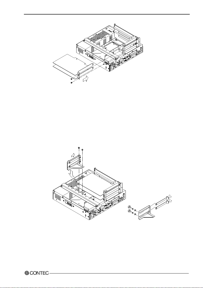
Note!
5. Each Component Function
Figure 5.27. Installation of an Expansion Board
Each slot allows either the PCI or ISA board to be installed.
Insert the board into the PCI connector when installing a PCI
board or into the ISA connector when installing an ISA board.
(5) Install the PCB brace. It can hold down a board if its height
is at least 68mm. This brace is assembled to fit the PCI card.
To use it with the ISA card, rotate the claws and reinstall them.
User’s Manual
Figure 5.28. Attaching the Figure 5.29. Adjusting to
PCB Brace Use the ISA
Card
(6) Replace the expansion slot cover.
85
Page 91

5. Each Component Function
Figure 5.30. Replacing the Top Cover
86 User’s Manual
Page 92

2. IPC-BX/M600(PCW)C4P
(1) Be sure the power is turned off.
(2) Remove the top cover.
5. Each Component Function
User’s Manual
Figure 5.31. Removing the Top Cover
87
Page 93

5. Each Component Function
(3) Remove the brace that holds the printed circuit board (PCB)
down.
Remove the screws on the brace. The brace will separate
toward you.
PCB brace
Figure 5.32. Removing the PCB Brace 2
(4) Insert the board into the slot and fasten it with screws.
Figure 5.33. Installation of an Expansion Board
Note!
The upper two slots accept only PCI boards while the lower two
accept either PCI or ISA boards.
Insert the board into the PCI connector when installing a PCI
board or into the ISA connector when installing an ISA board.
88 User’s Manual
Page 94

5. Each Component Function
(5) Install the PCB brace. It can hold down a board if its height
is at least 68mm. This brace is assembled to fit the PCI card.
To use it with the ISA card, rotate the claws and reinstall them.
Figure 5.34. Attaching the Figure 5.35. Adjusting to
PCB Brace Use the ISA
Card
(6) Replace the expansion slot cover.
User’s Manual
Figure 5.36. Replacing the Top Cover
89
Page 95

5. Each Component Function
90 User’s Manual
Page 96

6. Appendix
Memory Map
FF FFFFF
0100000
00F FFFF
00E0000
00DFFFF
00D0000
00CFFFF
00CC000
00CBFFF
00C0000
00BFFFF
00A0000
009FF FF
0000000
Expansion memory area
Main BIOS
(128KB)
Expansion ROM area
(Free to the user)
Reserved for BIOS
VGA BIOS
(48KB)
Video RAM area
(128KB)
RAM
(640KB)
6. Appendix
User’s Manual
Figure 6.1. Memory Map
91
Page 97

6. Appendix
I/O Port Addresses
Table 6.1. I/O Port Addresses
ADDRESS(HEX) Description Remark
000-00F DMA controller 1 (slave) ch0-3 (8-bit transfer)
010-01F Reserved for system
020-03F Interrupt controller 1 (master)
040-05F Timer
060-06F Keyboard controller
070-07F RTC, NMI mask
080-09F DMA page register
0A0-0BF Interrupt controller 2 (slave)
0C0-0DF DMA controller 2 (master) ch5-7 (16-bit transfer)
0E0-0FF Reserved for system
100-12F Available to user Available to expansion bus (CP and C4P models)
140-16F Available to user Available to expansion bus (CP and C4P models)
170-17F IDE hard disk controller Secondary
180-18F Reserved for system
190-1DF Available to user Available to expansion bus (CP and C4P models)
1E8-1EF Reserved for system
1F0-1FF IDE hard disk controller Primary
200-277 Available to user Available to expansion bus (CP and C4P models)
278-27F Reserved for parallel port LPT2
280-2E7 Available to user Available to expansion bus (CP and C4P models)
2E8-2EF Reserved for serial port COM4
2F0-2F7 Available to user Available to expansion bus (CP and C4P models)
2F8-2EF Serial port COM2
300-35F Available to user Available to expansion bus (CP and C4P models)
370-375 Reserved for system
376-377 IDE hard disk controller Secondary
378-3AF Reserved for parallel port LPT1
3B0-3BB Reserved for system
3BC-3BF Reserved for parallel port LPT3
3C0-3DF Reserved for system
3E0-3E7 PCMCIA C, CP and C4P models
3E8-3EF Serial port COM3 (Touch panel, Default factory setting)
3F0-3F7 FD controller
3F8-3FF Serial port COM1
4D0-4DF Reserved for system
CF0-CFF Reserved for system
4000-4007 RAS functions
4008-400F Reserved for system
46E8 Reserved for system
83D0-B3D3 Reserved for system
92 User’s Manual
Page 98

Interrupt Level List
Table 6.2. Hardware Interrupt Levels (Factory Settings)
Type 8259 Priority Vector Remarks
NMI High I/O CH CK or WDT 02H
IRQ0 MASTER ↑ Timer 0 08H
IRQ1 " | Keyboard 09H
IRQ2 " | Interrupt controller 2 (slave) 0AH
IRQ8 SLAVE | Real-time clock 70H
IRQ9 " | Not in use 71H Available to user
IRQ10 " | Not in use 72H Available to user
IRQ11 " | Reserved for PCI device 73H
IRQ12 " | Reserved for PS/2 mouse 74H
IRQ13 " | Reserved for coprocessor 75H
IRQ14 " | Reserved for hard disk 76H Primary
IRQ15 " | Reserved for optional CD-ROM 77H Secondary
IRQ3 MASTER | Serial port B (COM2) 0BH
IRQ4 " | Serial port A (COM1) 0CH
IRQ5 " | Not in use 0DH Available to user
IRQ6 " ↓ Reserved for floppy disk 0EH
IRQ7 " Low Serial port C (touch panel) 0FH Touch panel (Default factory setting)
Description
* Do not use for ISA devices.
6. Appendix
User’s Manual
93
Page 99

6. Appendix
94 User’s Manual
Page 100

7. List of Options
Memories (144pin SO-DIMM)
- PC-MSD64-144H 64MB SD memory module
- PC-MSD128-144H 128MB SD memory module
Hard disk (IDE 2.5inch)
- PC-HDD20G 20GB Hard disk
Silicon disk (IDE 2.5inch)
- PC-SDD500H 512MB Flash silicon disk
- PC-SDD1000H 1GB Flash silicon disk
- PC-SDD2000V 2GB silicon disk drive
Floppy disk drive
- PC-FDD25BH 3.5inch floppy disk drive (comes with a cable)
(Note: Required to install the LAN driver.)
Terminal block for connecting the RAS connector
- IPC-PSD-20 Terminal block for connecting the RAS connector
7. List of Options
User’s Manual
TFT color liquid-crystal display
< Analog RGB/DVI-D types>
- IPC-DT/S61VT-DC1 (6.5inch 640 x 480 dot s, Panel
mounted type)
- IPC-DT/S65VT-DC1 (6.5inch 640 x 480 dot s, Embedded
type)
<Panel Link types>
- IPC-DT/H40X(PC)T (15.0inch 1024 x 768 dots, Panel
mounted type)
- IPC-DT/L40S(PC)T (12.1 inch 800 x 600 dots, Panel
mounted type)
- IPC-DT/L440(PC)TA (12.1 inch 800 x 600 dots,
Desktop/wall-mounted)
- IPC-DT/L440(PC)TB (12.1 inch800 x 600 dots,
Desktop/wall-mounted, anti-glare type)
95
 Loading...