

Page 1

IPC Series
BOX-PC 955S Series
Fanless, Atom N2600
CFast, DC input
User’s Manual
CONTEC CO.,LTD.
Page 2

Check Your Package
Thank you for purchasing the CONTEC product.
The product consists of the items listed below.
Check, with the following list, that your package is complete. If you discover damaged or missing
items, contact your retailer. If you use driver&utility software set, download it from the CONTEC’s
Web site.
Product Configuration List
Name Pcs. Pcs. Pcs.
BOX-PC
The attachment fittings
CFast card removal prevention fitting 1 1 1*1 1*1
CFast card removal prevention fitting 2 1 1 1
USB removal prevention fitting (base) 1 1 1
USB removal prevention fi tting (angle) 4 4 4
Washer assembled sc rew (M3 x 6) 4 4 4
Washer assembled screw (M3 x 8, black) 6 6 6
Washer assembled and cross recessed
hexagonal bolt (M4 x 10, black)
Power supply connector complete set
Power connector 1 1 1
Contact 4 4 4
Cable clamp
DVI-analog RGB conversion adapter
Product guide (this sheet)
IPC Precaution List 1 1 1
Warranty Certificate 1 1 1
Serial number label 1 1 1
Royalty consent contract
Setup Procedure Document
Notes on Windows Embedded Standard
Notes on using Windows Embedded
Standard 7 & Setup Procedure Document
Recovery Media *2
*1 It is attached to the main body.
*2 Please confirm latest information on the CONTEC homepage.
BX-955SD-DC6000
[Base Model]
1 1 1
2 2 2
4 4 4
2 2 2
1 1 1
1 1 1
― 1 1
― 1 ―
― 1 ―
― ― 1
― 1 1
BX-955S-DC6311
[WES2009 Model
(VGA)]
BX-955SD-DC6311
[WES2009 Model
(DVI)]
BX-955SD-DC6312
[WES7 Model]
BX-955Sx Series User’s manual
i
Page 3

Product Configuration Image
BOX-PC
(BX-955Sx)
Washer assembled
screw (M3 x 6)
Washer assembled
screw (M3 x 8, black)
Product
guide
Product guide
* See the Product Configuration List to check if all the components are included for the specified number of units.
The attach
ment fittings
Washer assembled and
cross recessed hexagonal bolt
(M4 x 10, bl ack)
DVI-analog RGB
conversion adapter
IPC
Precaution
List
IPC Precaution
List
CFast card remov al
prevention fitting 1
Power supp ly connect or
complete set
Warrant y
Certificate
War ran ty
Certificate
Power connector
Contact
XXXXXXXXXXXXX
XXXXXXXXXXXXX
Serial number
label
CFast card removal
prevention fitting 2
USB removal prevention
fitting (angle)
Royalty
consent
contract
Royalty consent
contract
USB removal prevention
fitting (base)
Cable clamp
Setup
Procedure
Document
Setup Procedure
Document
Notes on using
Window s
Embedded
Standard
Notes on using
Windows Embedded
Standard
Recovery Media
Copyright
Copyright 2013 CONTEC CO., LTD. All Rights Reserv ed .
No part of this document may be copied or reproduced in any form by any means without prior written
consent of CONTEC CO., LTD.
CONTEC CO., LTD. makes no commitment to update or keep current the information contained in this
document.
The information in this document is subject to change without notice.
All relevant issues have been considered in the preparation of this document. Should you notice an
omission or any questionable item in this document, please feel free to notify CONTEC CO., LTD.
Regardless of the foregoing statement, CONTEC assumes no responsibility for any errors that may
appear in this document or for results obtained by the user as a result of using this product.
Trademarks
Intel, Intel Atom, Intel Core and Celeron are registered trademarks of Intel Corporation. MS, Microsoft
and Windows are trademarks of Microsoft Corporation. Other brand and product names are trademarks
of their respective holder.
BX-955Sx Series User’s manual
ii
Page 4

Table of Contents
Check your p ackage .................................................................................................................................i
Copyright.................................................................................................................................................ii
Trademarks ..............................................................................................................................................ii
Table of Contents ...................................................................................................................................iii
1. INTRODUCTION 1
About the P roduct ...................................................................................................................................1
Features ............................................................................................................................................ 1
Supported O S ...................................................................................................................................2
Customer Support.................................................................................................................................... 3
Web Site ...........................................................................................................................................3
Limited One -Year Warranty...................................................................................................................3
How to Obta in Service............................................................................................................................ 3
Liability ...................................................................................................................................................3
Safety Precautions...................................................................................................................................4
Safety Inf ormation ...........................................................................................................................4
Caution on the BX-955S x Series................................................................................................. .... 4
2. SYSTEM REFERENCE 7
Specification............................................................................................................................................7
Power Mana gement Features .................................................................................................................. 9
Power Requ irements .............................................................................................................................10
Power Consumption.......................................................................................................................10
Physical D imensions .............................................................................................................................11
3. HARDWARE SETUP 13
Before Using the Product for the First Time ........................................................................................ 13
Hardware Setup..................................................................................................................................... 14
Attaching the CFast Attachment Fittings...................................................................................... 14
Attaching the Attachment Fittings ................................................................................................14
Attaching the FG............................................................................................................................15
Fastening t he Cable........................................................................................................................16
Installation of VESA metal fittings...............................................................................................17
Installation Requirements ..............................................................................................................18
4. EACH COMPONENT FUNCTION 21
Component Name..................................................................................................................................21
Front View......................................................................................................................................21
BX-955Sx Series User’s manual
iii
Page 5

Side View........................................................................................................................................21
System Configuration........................................................................................................... .................22
Component Function.............................................................................................................................23
LED: POWER , ACCESS, ST ATUS .............................................................................................23
DC Power In put Connect or : DC-IN .............................................................................................23
POWER SW ...................................................................................................................................24
Line out Interface: LINE OUT ......................................................................................................24
MIC in Interface: MIC ...................................................................................................................24
Giga bit-Ethernet: LAN A – B.......................................................................................................25
USB Ports .......................................................................................................................................26
Serial Port Interface : SERIAL A - B ............................................................................................27
Serial Port Interface : SERIAL A - B ............................................................................................27
DVI Interface : DVI .......................................................................................................................28
CFast Card Connector (Primary IDE Connection) : CFast1......................................................... 30
5. BIOS SETUP 31
Introduction............................................................................................................................................31
Starting S e tup.........................................................................................................................................31
Using Setu p............................................................................................................................................32
Getting Help ...................................................................................................................................32
In Case of Problems .......................................................................................................................32
A Final Note About Setu p..............................................................................................................32
Main Menu.............................................................................................................................................33
Setup Items .....................................................................................................................................33
Main .......................................................................................................................................................34
Advanced ...............................................................................................................................................35
PCI Subsys tem Setting s .................................................................................................................37
ACPI Settings .................................................................................................................................38
CPU Config uration.........................................................................................................................39
IDE Config uration..........................................................................................................................40
USB Config uration.........................................................................................................................41
Super I/O Configuration.................................................................................................................42
Serial Por t A Configura tion ...........................................................................................................43
Serial Por t B Configura tion............................................................................................................44
Hardware Monitor ..........................................................................................................................45
PPM Config uration.........................................................................................................................46
Chipset ...................................................................................................................................................47
Host Bridg e.....................................................................................................................................48
Memory Fre quency and T iming ....................................................................................................49
Intel IGD C o nfiguration .................................................................................................................50
South Brid ge...................................................................................................................................51
TPT Device s ...................................................................................................................................53
Boot........................................................................................................................................................55
BX-955Sx Series User’s manual
iv
Page 6

Security.................................................................................................................................................. 56
Save & Exit ........................................................................................................................................... 57
POST Beep ............................................................................................................................................59
Position and Settings of the ROM Clear Switches ..............................................................................60
6. APPENDIX 61
Memory Map .........................................................................................................................................61
I/O Port Ad dresses ................................................................................................................................62
Interrupt Level List ...............................................................................................................................63
POST Codes ..........................................................................................................................................64
SERIAL I/O Address and Register F u nction....................................................................................... 66
Watch-Dog-Timer .................................................................................................................................72
Status LED ............................................................................................................................................ 76
Battery ...................................................................................................................................................78
Differenc e Between BX - 955 and BX-9 55S......................................................................................... 78
7. LIST OF OPTIONS 79
BX-955Sx Series User’s manual
v
Page 7

BX-955Sx Series User’s manual
vi
Page 8

1. Introduction
1. Introduction
About the Product
This product is a small PC for embedded use that is equipped with an Intel
low-power, dual core processor.
This product has a fanless and slitless case, uses CFast for storage, and has a completely spindleless
design.
This product is equipped with various expansion interfaces such as 1000BASE-T, USB 2.0, and serial.
This product is the successor to the BX955 and has achieved high calculation capabilities such as an
improved CPU processing capability that is twice that of its predecessor. In addition, this product assists
our customers in their implementations of plans to reduce running costs and energy usage. Thanks to
its installation compatibility, this product can be swapped into existing systems.
Its rich variety of expansion interfaces, such as 1000BASE-T, USB 2.0, and serial, and its usage of
CFast cards for storage enable this product to be designed in a completely spindleless manner.
This product is available in the following 4 models :
(R)
- Base model with Intel
BX-955SD-DC6000 (Memory 2GB, without OS, CFast card)
- Windows Embedded Standard 2009 model, VGA type with Intel
BX-955S-DC6311 (Memory 2GB, with OS, 4GB, CFast card)
- Windows Embedded Standard 2009 model, DVI type with Intel
BX-955SD-DC6311 (Memory 2GB, with OS, 4GB, CFast card)
- Windows Embedded Standard 7 model with Intel
BX-955SD-DC6312 (Memory 2GB, with OS, 8GB, CFast card)
Atom Processor N2600 1.6GHz
(R)
Atom Processor N2600 1.6GHz
Features
- Dual core energy saving processor with HyperThreading Technology
This product uses a dual core, four-thread Intel
product to perform stable concurrent processing at the same time of multiple applications such as
communication, control, and HMI applications.
Compared to the conventional BX955, this product boasts CPU performance that is twice that of its
predecessor, which enables this product to be applied to uses that require higher levels of calculation
processing.
(R)
Atom N2600 1.6 GHz processor. This enables the
(R)
Atom N2600 1.6 GHz,
(R)
Atom Processor N2600 1.6GHz
(R)
Atom Processor N2600 1.6GHz
- Contributes to Reductions in Running Cost and Energy Usage
Although this product guarantees sufficient performance, it sports low power consumption. The
slitless and fanless design leads to a reduction in maintenance and inspection work. What's more, as a
resource-saving PC, this product assists our customers in their implementations of plans to reduce
running costs and energy usage.
BX-955Sx Series User’s manual
1
Page 9

1. Introduction
- Serving the downsizing of equipment, a small footprint design for A5-sized installation area
This product adopts space-saving design of 182(W) x 155(D) x 35(H), permitting placement in the
smaller, A5-sized space with opening of only 50mm. It largely serves downsizing of your equipment,
fits any area with the aestheticness kept. It is also possible to attach to the VESA standard 75 x 75, 100
x 100mm using the optional fittings.
- Remote power management function to reduce operation tasks
This product supports timed/automated system start-up (Resume By Alarm). For example, it enables
unattended operation, such as starting to show information of an establishment in unison at opening
time. Also, it supports system start-up externally via network (Wake On LAN) and modem (Power On
by Ring). It encourages significant labor saving in operation.
- Major types of peripherals are supported with rich interfaces including two CFast card slots
It has a variety of extended interface such as 1000BASE-T x 2, USB2.0 x 4, serial (RS-232C) x 2.
It has two CFast card slots that can use for OS and data. They are very useful because you can use one
slot for system start-up and the other for maintenance, system log, or taking away the collected data.
- Falling-off prevention tools and fixing clamps
provided to avoid trouble caused by
disconnected cable
This product stays trouble-free, being equipped
with USB removal prevention fitting and cable
clamp for connectors with no locking mechanism,
such as USB cable, and with hardware to properly
mount and avoid falling out of CFast card.
- Safety design required for embedded applications
For Windows Embedded Standard installed model, it is possible to use the EWF*1 function of OS. It is
designed for safety required for embedding purpose, for example, prohibiting unwanted writing to the
CFast card with EWF function will relieve the concern about the writing limits to the CFast card and
prevent an unintentional system alteration.
*1 EWF (Enhanced Write Filter) is a function specific to Windows Embedded Standard that protects the disk from being actually
written by
redirecting the writing to RAM.
- A wide range of power supplies (10.8 - 31.2VDC) supported
As the product supports a wide range of power (10.8 - 31.2VDC), it can be used in a variety of power
environments. The separately available AC adapter adds support for 100VAC power.
Supported OS
- Windows Embedded Standard 2009
- Windows Embedded Standard 7
BX-955Sx Series User’s manual
2
Page 10

1. Introduction
Customer Support
CONTEC provides the following support services for you to use CONTEC products more efficiently
and comfortably.
Web Site
Japanese http://www.contec.co.jp/
English http://www.contec.com/
Chinese http://www.contec.com.cn/
Latest product information
CONTEC provides up-to-date information on products.
CONTEC also provides product manuals and various technical documents in the PDF.
Free download
You can download updated driver software and differential files as well as sample programs available in
several languages.
Note! For product information
Contact your retailer if you have any technical question about a CONTEC product or need its price,
delivery time, or estimate information.
Limited One-Year Warranty
CONTEC products are warranted by CONTEC CO., LTD. to be free from defects in material and
workmanship for up to one year from the date of purchase by the original purchaser.
Repair will be free of charge only when this device is returned freight prepaid with a copy of the
original invoice and a Return Merchandise Authorization to the distributor or the CONTEC group office,
from which it was purchased.
This warranty is not applicable for scratches or normal wear, but only for the electronic circuitry and
original products. The warranty is not applicable if the device has been tampered with or damaged
through abuse, mistreatment, neglect, or unreasonable use, or if the original invoice is not included, in
which case repairs will be considered beyond the warranty policy.
How to Obtain Service
For replacement or repair, return the device freight prepaid, with a copy of the original invoice. Please
obtain a Return Merchandise Authorization number (RMA) from the CONTEC group office where you
purchased before returning any product.
* No product will be accepted by CONTEC group without the RMA number.
Liability
The obligation of the warrantor is solely to repair or replace the product. In no event will the warrantor
be liable for any incidental or consequential damages due to such defect or consequences that arise from
inexperienced usage, misuse, or malfunction of this device.
BX-955Sx Series User’s manual
3
Page 11

1. Introduction
Safety Precautions
Understand the following definitions and precautions to use the product safely.
Safety Information
This document provides safety information using the following symbols to prevent accidents resulting
in injury or death and the destruction of equipment and resources. Understand the meanings of these
labels to operate the equipment safely.
DANGER
WAR NI NG
CAUTION
Caution on the BX-955Sx Series
DANGER indicates an imminently hazardous situation which, if not avoided, will
result in death or serious injury.
WARNING indicates a potentially hazardous situation which, if not avoided, could
result in death or serious injury.
CAUTION indicates a potentially hazardous situation which, if not avoided, may
result in minor or moderate injury or in property damage.
Handling Precautions
WA RN IN G
- Always check that the power supply is turned off before connecting or disconnecting power cables.
- Do not modify the product.
- Always turn off the power before inserting or removing circuit boards or cables.
- This product is not intended for use in aerospace, space, nuclear power, medical equipment, or other
applications that require a very high level of reliability. Do not use the product in such applications.
- If using this product in applications where safety is critical such as in railways, automotive, or
disaster prevention or security systems, please contact your retailer.
- Do not attempt to replace the battery as inappropriate battery replacement poses a risk of explosion.
- For battery replacement, contact your retailer as it must be performed as a process of repair.
- When disposing of a used battery, follow the disposal procedures stipulated under the relevant laws
and municipal ordinances.
BX-955Sx Series User’s manual
4
Page 12

1. Introduction
CAUTION
- Do not use or store this product in a location exposed to high or low temperature that exceeds range
of specification or susceptible to rapid temperature changes.
Example: - Exposure to direct sun
- In the vicinity of a heat source
- Do not use this product in extremely humid or dusty locations. It is extremely dangerous to use this
product with its interior penetrated by water or any other fluid or conductive dust. If this product
must be used in such an environment, install it on a dust-proof control panel, for example.
- Avoid using or storing this product in locations subject to shock or vibration that exceeds range of
specification.
- Do not use this product in the vicinity of devices that generate strong magnetic force or noise. Such
products will cause this product to malfunction.
- Do not use or store this product in the presence of chemicals.
- To clean this product, wipe it gently with a soft cloth dampened with either water or mild detergent.
Do not use chemicals or a volatile solvent, such as benzene or thinner, to prevent pealing or
discoloration of the paint.
- This product’s case may become hot. To avoid being burned, do not touch that section while this
product is in operation or immediately after turning off the power. Avoid installation in a location
where people may come into contact with that section.
- CONTEC does not provide any guarantee for the integrity of data on CFast card.
- Always disconnect the power cable from the receptacle before mounting or removing the expansion
board, or before connecting or disconnecting any connector.
- To prevent corruption of files, always shutdown the OS before turning off this product.
- CONTEC reserves the right to refuse to service a product modified by the user.
- In the event of failure or abnormality (foul smells or excessive heat generation), unplug the power
cord immediately and contact your retailer.
- To connect with peripherals, use a grounded, shielded cable.
- The CFast card connector doesn't support hot plug. While this product is turned on, do not insert
or remove the CFast card or touch the CFast card connector on the product. This product may
malfunction or cause a failure.
- Component Life:
(1) Battery---The intern al calendar clock and CMOS RAM are backed by a Lithium primary battery.
(2) CFast---The CFast model uses a CFast in the OS storage area.
* Replacement of expendables is handled as a repair (there will be a charge).
* Component life is not guaranteed value but only referential value.
The backup time at a temperature of 25°C with the power disconnected is 10 years.
The NandFlash can be rewritten 60,000 times or more.
As a reference value, the rewritable lifetime can be determined by the following
calculation.
Rewritable lifetime (number of times) = ((capacity [MB] / management block size
[MB]) × 60,000 times) / (number of management blocks rewritten each time)
Example: If a 4 MB file is created and is rewritten once every 10 seconds
Rewritable lifetime = ((3577/2) × 60000)) / 2 = 53,655,000 (number of times)
≒
Lifetime = 53,655,000 / ((60/10) × 60 × 24 × 365)
17 (year)
BX-955Sx Series User’s manual
5
Page 13

1. Introduction
FCC PART 15 Class A Notice
NOTE
This equipment has been tested and found to comply with the limits for a Class A digital device,
pursuant to part 15 of the FCC Rules. These limits are designed to provide reasonable protection
against harmful interference when the equipment is operated in commercial environment.
This equipment generates, uses, and can radiate radio frequency energy and, if not installed and
used in accordance with the instruction manual, may cause harmful interference to radio
communications. Operation of this equipment in a residential area is likely to cause harmful
interference at his own expense.
WARNING TO USER
Change or modifications not expressly approved the manufacturer can void the user's authority to
operate this equipment.
BX-955Sx Series User’s manual
6
Page 14

2. System Reference
System Reference
2.
Specification
Table 2.1. Functional Specification < 1 / 2 >
Model BX-955Sx-DC6xxx
CPU Intel
Chip set Intel
BIOS BIOS (mfd. by AMI)
Memory 2GB (204pin SO-DIMM×1), PC3-8500 DDR3 SDRAM
Video
System
resolution
*1*2
Audio HD Audio compliant
CFast card slot 2 slots, CFast CARD Type I , bootable
Serial I/F
*1 : It may not be possible for the screen to be displayed correctly depending on the specifications of the connected
*2 : On Windows Embedded Standard 2009, the primary display is fixed as shown below.
BX-955SD-6311 : DVI
BX-955S-6311 : Analog RGB
*3 : You cannot set the resolution to 1,920 × 1,200 when the OS is Windows Embedded Standard 7 and an analog RGB
Controller
Video RAM Main memory shared
Video BIOS 64KB(C0000H-CFFFFH)
Display I/F DVI-I I/F x 1(29 pin connector x 1)
DVI 640 x 480, 800 x 600, 1,024 x 768, 1,280 x 768, 1,280 x 1,024, 1,360 x 768, 1,400 x 1,050,
Analog RGB 640 x 480, 800 x 600, 1,024 x 768, 1,280 x 768, 1,280 x 1,024, 1,360 x 768, 1,400 x 1,050,
display.
Also, when an analog RGB display is connected and when the OS is Windows Embedded Standard 7 and a DVI
display is connected, although all the resolutions shown in this table can be set for the resolution setting of the OS,
use the product with a resolution that matches the specifications of the connected display.
display is connected.
(R)
Atom™ Processor N2600 (1.6GHz)
(R)
NM10
(R)
Intel
GMA3650 (with Intel
1,600 x 900, 1,600 x 1,200, 1,920 x 1,080, 1,920 x 1,200 (16,770,000 colors)
1,600 x 900, 1,600 x 1,200, 1,920 x 1,080, 1,920 x 1,200 *3 (16,770,000 colors)
LINE OUT: φ3.5 Stereo mini jack
Full-scale output level 1.2Vrms(Typ.),
MIC IN: φ3.5 Stereo mini jack
Full-scale input level 1.5Vrms(Typ.)
BX-955SD-DC6000 : BX-955S-DC6311, BX-955SD-DC6311 : CFast is finished mounting. (4GB)
BX-955SD-DC6312 : CFast is finished mounting. (8GB)
RS-232C (general-purpose) : 2ch(SERIAL PORT1,2) 9pin D-SUB connector (male)
Baud rate : 50 - 115,200bps
(R)
Atom™ Processor N2600)
BX-955Sx Series User’s manual
7
Page 15

2. System Reference
Table 2.1. Functional Specification < 2 / 2 >
Model BX-955Sx-DC6xxx
I/F 1000BASE-T/100BASE-TX/10BASE-T RJ-45 connector x 2(Wake On LAN support) LAN
*4
Controller LAN-A : Realtek 8111E Controller
LAN-B : Realtek 8111E Controller
USB I/F 4channels (USB 2.0-compliant)
Keyboard/mouse I/F None *5
General-purpose I/O None
Hardware monitoring Monitoring CPU temperature, board temperature, power voltage
Watch dog timer Software programmable, 255 level (1sec - 255 sec)
Causes a reset upon time-out.
RTC/CMOS Lithium backup battery life : 10 years or more
Power Management Power management setup via BIOS
Rated input
Power
voltage
supply
Range of
input voltage
Power
consumption
External
device power
supply
capacity
Physical dimensions
(mm)
Weight About 1.3kg
*4 : If you use the 1000BASE-T, be careful of the operating temperature.
For more details on this, refer to chapter3, Installation Requirements.
*5 : Use USB I/F for the keyboard / mouse.
*6 : Use a power cable shorter than 3m.
The real-time clock is accurate within ±3 minutes (at 25°C) per month
Power On by Ring / Wake On LAN
Supports ACPI Power management
12 - 24VDC *6
10.8 - 31.2VDC
12V 2.5A (Max.), 24V 1.4A (Max.)
- CFast card slot : +3.3V 1A (500mA x 2)
- USB I/F : +5V 2A (500mA x 4)
182(W) x 155(D) x 35(H) (No protrusions)
BX-955Sx Series User’s manual
8
Page 16

2. System Reference
Table 2.2. Installation Environment Requirements
Model BX-955Sx-DC6xxx
Operating temperature
*1
Storage temperature
Humidity
Floating dust particles
Corrosive gases
Line noise
Ambient
specifications
*1 : For more details on this, please refer to chapter 3, “Installation Requirements”.
*2 : When IPC-ACAP12-04A is used.
Line-noise
resistance
Vibration
resistance
Impact resistance
Grounding
Static
electricity
resistance
Sweep
resistance
0 - 50°C (When using 1000BASE-T : 0 - 45°C)
-10 - 60°C
10 - 90%RH (No condensation)
Not to be excessive
None
AC line / ±2kV *2,
Signal line / ±1kV (IEC61000-4-4 Level 3, EN61000-4-4 Level 3)
Contact discharge / ±4kV (IEC61000-4-2 Level 2, EN61000-4-2 Level 2)
Atmospheric discharge / ±8kV (IEC61000-4-2 Level 3, EN61000-4-2 Level 3)
10 - 57Hz/semi-amplitude 0.375 mm 57 - 500Hz/5.0G
60 min. each in x, y, and z directions
(JIS C 60028-2-6-compliant, IEC 60068-2-6-compliant)
100G, half-sine shock for 6 ms in x, y, and z directions
(JIS C 60068-2-27-compliant, IEC 60068-2-27-compliant)
Class D grounding (previous class 3 grounding), SG-FG / continuity
Power Management Features
- Support both ACPI (Advanced Configuration and Power Interface) and legacy (APM) power
management.
- ACPI v4.0 compliant
- Support hardware automatic wake-up
BX-955Sx Series User’s manual
9
Page 17

2. System Reference
Power Requirements
Your system requires a clean, steady power source for reliable performance of the high frequency CPU
on the product, the quality of the power supply is even more important. For the best performance makes
sure your power supply provides a range of 10.8 V minimum to 31.2 V maximum DC power source.
Power Consumpti o n
For typical configurations, the CPU card is designed to operate with at least a 60W power supply. The
power supply must meet the following requirements :
- Rise time for power supply: 2 ms - 30 ms
The following table lists the power supply’s tolerances for DC voltages:
Table 2.3. DC voltage tolerance
DC Voltage Acceptable Tolerance
+ 12V - 24V + 10.8V - 31.2V
BX-955Sx Series User’s manual
10
Page 18

2. System Reference
Physical Dimensions
BX-955Sx-DC6xxx
M4 screws *1
(Maximum tapping
218
200
100
length : 8mm)
8-φ5
5
M3 screws *2
(Maximum tapping
length : 6mm)
12515100
155
1407.5
27.5
(6)
35
[mm]
Surface of
the cabinet
L
182
A B
12 - 24
VDC
2
CFA
1
A
B
STATUS
*1 : The length (L) from the surface of the cabinet to the screw tip should be 8mm or less.
*2 : When you fasten the bundled attachment fittings to be fixed to the body, you should use the attached screws
(M3 x 8).
Otherwise, the length (L) from the surface of the cabinet to the screw tip should be 6mm or less.
Figure 2.1. BX-955Sx-DC6xxx
BX-955Sx Series User’s manual
11
Page 19

2. System Reference
BX-955Sx Series User’s manual
12
Page 20

3. Hardware Setup
3. Hardware Setup
Before Using the Product for the First Time
Follow the next steps to set up this product:
STEP1 By referring to the information in this chapter, install, connect and set this product.
STEP2 Connect cables.
Connect the cable of necessary external devices, such as keyboard and a display, to this
product using appropriate cables.
STEP3 Turn on the power.
After verifying that you have correctly followed steps 1 and 2, turn on the power.
If you find any abnormality after turning on the power, turn it off and check to see if the
setup has been performed properly.
STEP4 Set up BIOS.
By referring to Chapter 5, set up BIOS. This setup requires a keyboard and a display.
*1 Before using this product, be sure to execute "Restore Defaults" to initialize the BIOS
settings to their default values.
(See Chapter 5, "Save & Exit".)
CAUTION
When you are using Windows Embedded Standard 2009, be sure to check that the BIOS setup has
been performed, and then, on the BIOS menu, set "VBIOS Select for OS" to "Other."
Set "Boot Display Type" to "DVI" for the DVI type (BX-955SD-DC6311) and to "CRT" for the
VGA type (BX-955S-DC6311). When you execute the Restore Defaults command of the BIOS,
"VBIOS Select for OS" is set to "Win 7" and "Boot Display Type" is set to "CRT + DVI."
See Chapter 5, "Intel IGD Configuration".
CAUTION
Be sure to connect the keyboard and mouse to it before turning the power on for the first time.
BX-955Sx Series User’s manual
13
Page 21

3. Hardware Setup
Hardware Setup
- Before you start, be sure that the power is turned off.
- Remove only those screws that are explained. Do not move any other screw.
Attaching the CFast Attachment Fittings
(1) After inserting a CFast Card, fasten the bundled CFast attachment fittings with a screw.
Figure 3.1. Attaching the CFast Atta chment Fittings
CAUTION
- Insert the CFast Card face up.
- Screw holes may be damaged if screws are tightened with a torque greater than the specified torque.
The specified tightening torque is 3 - 3.5kgf⋅cm.
Attaching the Attachment Fittings
(1) Use screws to attach the bundled attachment fittings with a screw.
Do not tighten screws with excess force.
* Attached screw (M3 x 8)
Figure 3.2. Attaching the Attachment Fittings
CAUTION
Screw holes may be damaged if screws are tightened with a torque greater than the specified torque.
The specified tightening torque is 5 - 6kgf ⋅cm.
BX-955Sx Series User’s manual
14
Page 22

3. Hardware Setup
Attaching the FG
(1) Use screws to attach the FG.
* Attached screw (M3 x 8)
Figure 3.3. Attaching the FG
CAUTION
The FG pin of this product is connected to the GND signal of the DC power connector (DC-IN).
Note that the connection cannot be cut off.
Screw holes may be damaged if screws are tightened with a torque greater than the specified
torque.The specified tightening torque is 5 - 6kgf⋅cm.
BX-955Sx Series User’s manual
15
Page 23

3. Hardware Setup
Fastening the Cable
This product comes with clamps for fixing cables.
Fastening the LINEOUT, USB Cable
(1) The system unit has a hole for attaching cable clamp to USB removal prevention fitting. Using a
cable clamp for a cable with lock-less connector, such as the LINEOUT and USB Cable, prevents
the connector from being unplugged. Use the cable ties and cable clamps appropriately according to
the connecting states and wiring directions of cables.
*1
*2
*1 Attached screw (M3 x 6)
*2 Attached screw (M3 x 8)
Figure 3.4. Attaching the cable clamp
(2) The photo below shows an example of using a cable clamp. Fix the cable with a clamp without
applying stress to the connector.
Figure 3.5. Using example of cable clamp
BX-955Sx Series User’s manual
16
Page 24

3. Hardware Setup
Installation of VESA metal fittings
This product complies with the VESA standard. For information on VESA attachment and on VESA
attachment metal fittings, see the following information.
You can fix this product to VESA holes with a pitch of 75 x 75 or 100 x 100 by using the following
VESA attachment metal fittings.
The VESA attachment metal fittings are optional products.
For more details on this, see Chapter 7.
Surface of
M4 Screws
(Maximum tapping length
: 8mm)
* The liquid crystal display is possible and weight that can be the installation it is 8 kg or less possible.
The length (L) from the surface of the cabinet to the screw tip should be 8mm or less.
Figure 3.6. Installation of VESA metal fittings
CAUTION
- If you tighten the screws with a tightening torque greater than that specified, the screw holes may
be damaged.
The appropriate tightening torque for the screws of the upper surface heat sink and side installation
metal fittings is 5 to 6 kgf•cm.
When using the VESA attachment metal fittings, the vibration resistance and impact resistance are
the values shown below.
(*When a CONTEC FPD-H75XT-DC1 [weight: 5.6 kg, pitch: 75 mm] is attached)
10 - 57Hz/semi-amplitude 0.075 mm, 57 - 150Hz/1.0G 40 min. each in x, y, and z directions
(JIS C0040-compliant, IEC 68-2-6-compliant)
10G, half-sine shock for 11 ms in x, y, and z directions
(JIS C0041-compliant, IEC 68-2-7-compliant)
- When the product is attached to the VESA attachment metal fittings, check the vibration resistance
and impact resistance of the display and the tightening torque of the screws before using the
product.
BX-955Sx Series User’s manual
the cabinet
L
17
Page 25

3. Hardware Setup
Installation Requirements
Be sure that the operating temperature is within the range specified in the installation environment
requirement by making space between the product and device that generates heat or exhaust air.
BX-955Sx-DC6xxx
Installable directions at operating temperature 0 - +50°C (When using 1000BASE-T : 0 - +45°C)
(3)
(4)
(5)
(6)
Connector
12 - 24
(1)
12 - 24
VDC
2
Floor
A B
1
CFA
A
B
STATUS
Wall
(2)
STATUS
A B
Ceiling
A
B
CFA
2
1
VDC
12 - 24
VDC
2
Wall
Wall
1
A
B
CFA
A B
STATUS
STATUS
A B
CFA
B
A
1
Wall
2
VDC
12 - 24
Connector
Figure 3.7. Installation Orientation (BX-955SD-DC6xxx)
CAUTION
Note that even though the ambient temperature is within the specified range, an operational
malfunction may occur if there is other device generating high heat; the radiation will influence the
product to increase its temperature.
BX-955Sx Series User’s manual
18
Page 26

3. Hardware Setup
Distances between this product and its vicinity
50mm or more
50mm
or more
100 mm
or more
50mm
or more
100 mm
or more
50mm
or more
2
12 - 24
VDC
A B
1
CFA
A
B
STATUS
Figure 3.8. Distances between this product and its vicinity
CAUTION
Do not install this product into the fully-sealed space except the case in which the internal
temperature is adjustable by equipment such as air conditioner. Troubles such as operational
malfunctions could be occurred by the temperature increase caused by long-term usage.
BX-955Sx Series User’s manual
19
Page 27

3. Hardware Setup
Operating temperature
In this product, the operating temperature is decided from the multiple measurement points as shown
below. When making use of the product, the air current should be adjusted to prevent that all the
temperatures measured at the measurement points exceed the specified temperature.
<Vertical installation>
measurement points
15
50
50
<Horizontal installation>
50 50 5050
1 CFA
A
A B
B
STATUS
[mm]
12 - 24
VDC
2
Figure 3.9. Operating temperature
BX-955Sx Series User’s manual
20
Page 28

4. Each Component Function
4.
Each Component Function
Component Name
Front View
BX-955Sx-DC6xxx
LINE
POWER
OUT
LED
12 - 24
MIC
IN
VDC
POWER
SW
DC-IN
Figure 4.1. Component Name < 1 / 2 >
Side View
BX-955Sx-DC6xxx
SERIAL B
Figure 4.1. Component Name < 2 / 2 >
Table 4.1. Component Function
Name Function
POWER-SW Power switch
POWER LED Power ON display LED
ACCESS LED CFast disk access display LED
STATUS LED Status LED
DC-IN DC power input connector
LINE OUT Line out (φ3.5 PHONE JACK)
MIC IN Mike in (φ3.5 PHONE JACK)
LAN A Ethernet 1000BASE-T/100BASE-TX/10BASE-T RJ-45 connector
LAN B Ethernet 1000BASE-T/100BASE-TX/10BASE-T RJ-45 connector
USB USB port connector x 4
SERIALA
SERIALB
DVI-I Display (29pin D-SUB/female)
CFast1 CFast card slot
CFast2 CFast card slot 2
DVI-I
A B
STATUS
STATUS
LED
SERIAL A
ACCESS LED
USB
2
LAN A
CFA
1
A
B
LAN B
CFast1CFast2
Serial port A connector (9pin D-SUB/male)
Serial port B connector (9pin D-SUB/male)
BX-955Sx Series User’s manual
21
Page 29
4. Each Component Function
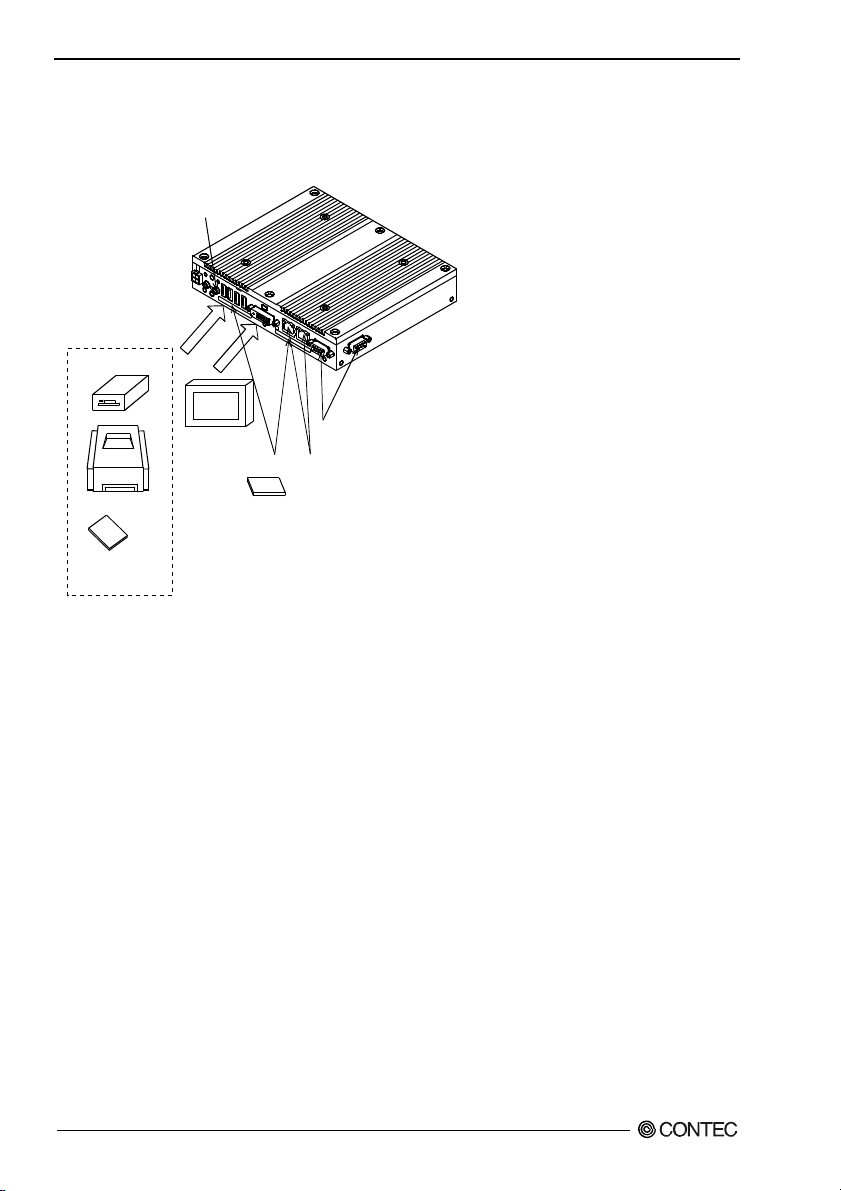
System Configuration
BX-955Sx-DC6xxx
LINE OUT
USB2.0
FD drive
Display
Serial port
CFast
card (1, 2)
Printer
USB device such
as CD-ROM drive
.,etc
Figure 4.2. System Configuration
(A, B)
LAN port
(A, B)
BX-955Sx Series User’s manual
22
Page 30
4. Each Component Function
Component Function
LED: POWER, ACCESS, STATUS
There are 3 LED in front of this product.
Table 4.2. Display Contents of LED
LED name State Display contents
OFF Indicates that this product is switched off. POWER LED
ON (Green) Indicates that this product is switched on.
ACCESS LED ON (Orange) Indicates that the CFast device is being accessed.
OFF You can control the behavior of LED from the user application. *1 STATUS LED
Flashing, ON (Red) You can control the behavior of LED from the user application. *1
*1 See Chapter 6, “Appendix”.
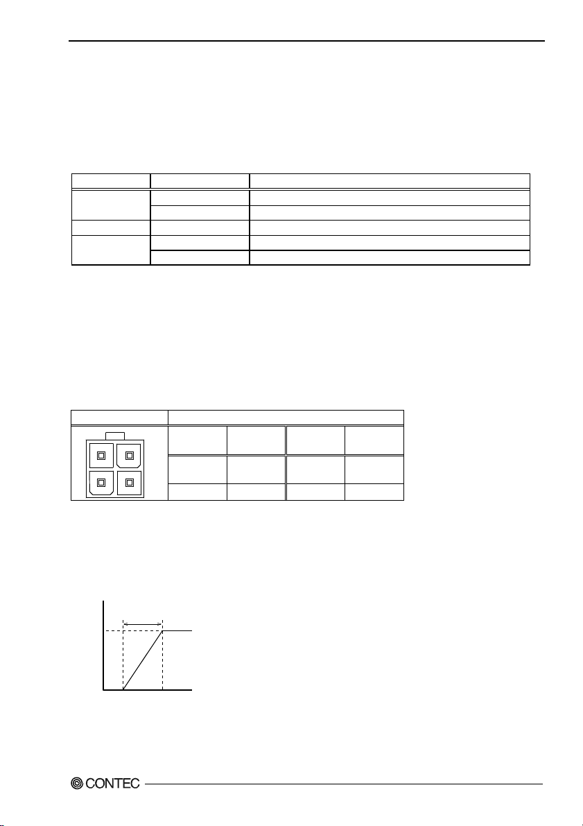
DC Power Input Connector : DC-IN
To supply the power, always use the power supply listed below.
Rated input voltage : 12 - 24VDC
Range of input voltage : 10.8 - 31.2VDC
Power capacity : 12V 2.5A or more, 24V 1.4A or more
Table 4.3. DC Power Connector
Connector type 9360-04P (mfd. by ALEX)
Pin No. Signal
43
21
4 12 - 24V 3 12 - 24V
2 GND 1 GND
name
Applicable connector on the connector side
Housing : 9357-04 (mfd. by ALEX) or 5557-04R (mfd. by MOLEX)
Contact : 4256T2-LF (AWG18-24) (mfd. by ALEX) or 5556 (AWG18-24) (mfd. by MOLEX)
Pin No. Signal
name
Rise time of power supply
Vol ta ge
12V
2 - 30mS
Time
Figure 4.3. Graph of Rise Time of Power Supply
BX-955Sx Series User’s manual
23
Page 31

4. Each Component Function
POWER SW
POWER SW is provided.
Line out Interface: LINE OUT
A line output connector is provided. You can plug a headphone or amplifier-integrated speakers into this
connector.
MIC in Interface: MIC
A MIC input connector is provided. You can plug a microphone to this connector for sound input.
Audio driver
The audio driver is required to use the microphone input and line output interfaces.
Install the appropriate audio driver for your OS from the CONTEC’s Web site.
BX-955Sx Series User’s manual
24
Page 32

4. Each Component Function
Giga bit-Ethernet: LAN A – B
This product is equipped with 2 ports for giga bit.
- Network type : 1000BASE-T/100BASE-TX/10BASE-T
- Transmission speed : 1000M/100M/10M bps
- Max. network path length : 100m/segment
- Controller : Realtek 8111E (LAN-A/B)
Table 4.4. Giga bit-Ethernet Connector
Function
LAN
Transmit
LED
81
Link
LED
Pin No.
100BASE-TX 1000BASE-T
1 TX+ TRD+(0)
2 TX- TRD-(0)
3 RX+ TRD+(1)
4 N.C. TRD+(2)
5 N.C. TRD-(2)
6 RX- TRD-(1)
7 N.C. TRD+(3)
8 N.C. TRD-(3)
LEDs for display of network statuses:
Right LED : Link LED
Normal connection : Green ON, Operation: Green Blinking
Left LED : Operation LED
10M : Off, 100M : Green, 1000M : Orange
LAN drivers
Install the appropriate audio driver for your OS from the CONTEC’s Web site.
CAUTION
When using any OS other than pre-installed one, LAN-1 and LAN-2 may not be assigned to silk
print “LAN-A” and “LAN-B” respectively.
BX-955Sx Series User’s manual
25
Page 33

4. Each Component Function
USB Ports
This product is equipped with 4 channels for USB 2.0 interface.
Table 4.5. USB Connector
Pin No. Function
1
4
1 USB_VCC
2 USB-
3 USB+
4 USB_GND
BX-955Sx Series User’s manual
26
Page 34

4. Each Component Function
Serial Port Interface : SERIAL A - B
SERIAL A,B
The product has 2 channels of serial ports supporting up to a baud rate of 115,200bps with a 16-byte
transmission-dedicated data buffer and a 16-byte reception-dedicated data buffer. You can use “Chapter
5 BIOS Setup” to configure an I/O address, interrupt and unused state for each of the ports
independently. (The same I/O address and IRQ cannot be shared with any other device.)
Please refer to “Chapter 6 I/O Port Addresses” for more information on I/O address and register
function.
Table 4.6. SERIAL A, B I/O Addresses and Interrupts
SERIAL
A 3F8h - 3FFh
B 2F8h - 2FFh IRQ 3
Table 4.7. Serial Port A, B Connector
Connector used on
the product
15
6
9
Signal
Pin No.
name
1 CD Carrier detect Input
2 RD Received data Input
3 TD Transmitted data Output
4 DTR Data terminal ready Output
5 GND Signal ground -----
6 DSR Data set ready Input
7 RTS Request to send Output
8 CTS Clear to send Input
9 RI Ring indicator Input
I/O address Interrupt
9-pin D-SUB (MALE)
No.4-40UNC
Inch screw
threads
Meaning Direction
IRQ 4
BX-955Sx Series User’s manual
27
Page 35

4. Each Component Function
DVI Interface : DVI
A DVI interface is provided. You can use it to connect a CRT (even a D-SUB 15 pin connector is
acceptable by using the bundled DVI-analog RGB adapter) or a CONTEC Panel Link display. The
connector is named DVI (DVI-I 29-pin connector).
CAUTION
For the Windows Embedded Standard 2009 DVI type (BX-955SD-DC6311), the BIOS SETUP
screen is only displayed on the display that is connected to the DVI connector.
Table 4.8 DVI Connector
Connector type DVI-I 29 pin
1
8
C1
C2
C5
16
17
9
Pin No.
1 DATA2- 13 N.C. C1 RED
2 DATA2+ 14 +5V C2 GREEN
3
4 N.C. 16 HPD C4 HSYNC
5 N.C. 17 DATA0- C5 GND
6 DDC CLK 18 DATA0+
7
8 VSYNC 20 N.C.
9 DATA1- 21 N.C.
10 DATA1+ 22
11
12 N.C. 24 CLK-
24
Signal
name
DATA2
SHIELD
DDC
DATA
DATA1
SHIELD
C4
C3
Pin No.
15 GND C3 BLUE
19
23 CLK+
Signal
name
DATA0
SHIELD
DATA0
SHIELD
Pin No.
Signal
name
BX-955Sx Series User’s manual
28
Page 36

4. Each Component Function
Table 4.9 DVI-analog RGB conversion adapter
Connector type DVI-I 29 pin
C4
C3
16
24
17
C5
C2
C1
8
39.40
1
1
33.00
5
6
11
15
10
15.00
Pin No. Pin No. Pin No. Pin No.
1 RED 9 +5V
2 GREEN 10 GND
3 BLUE 11 N.C.
4 N.C. 12 DDC DATA
5 GND 13 HSYNC
6 GND 14 VSYNC
7 GND 15 DDC CLK
8 GND
6.20 5.80
30.00
Signal on analog RGB
[mm]
Display driver
Install the appropriate audio driver for your OS from the CONTEC’s Web site
CAUTION
- For Windows Embedded Standard 2009, the primary display cannot be changed.
- If you connect to the RGB connector displays that process the unused pins in a special manner, the
PC may not start.
- For the Windows Embedded Standard 2009 RGB model (BX-955S-DC6311), the BIOS SETUP
screen is only displayed on the display that is connected to the RGB connector.
- For Windows Embedded Standard 2009, you need to set the screen resolution if the display cable is
not connected to this DVI-D interface at OS startup, but connected after OS startup (hereinafter
referred to as “Late Insertion”).
- On Windows Embedded Standard 7, if you start the OS and then connect the display cable, the
screen may not be displayed.
- For the Windows Embedded Standard 7 model (BX-955SD-DC6312), the BIOS SETUP screen
may not be displayed when some RGB displays are connected. In this situation, connect a
different RGB display, and then set "Boot Display Type" to "CRT" on the "Intel IGD
Configuration" menu.
BX-955Sx Series User’s manual
29
Page 37

4. Each Component Function
CFast Card Connector (Primary IDE Connection) : CFast1
The CFast Card (Type I) can be connected.
The CFast card connector doesn't support hot plug. Please neither pulling out opening of CFast in the
state of power supply ON of this product nor come in contact with CFast. This product may malfunction
or cause a failure.
Table 4.10. CFast Card Connector
Connector used
on the product
CFast Connector
Pin No. Signal name Pin No. Signal name
S1 GND PC1 CDI
S2 TX+ PC2 GND
S3 TX- PC3 N.C.
S4 GND PC4 N.C.
S5 RX- PC5 N.C.
S6 RX+ PC6 N.C.
S7 GND PC7 GND
PC8 LED
PC9 N.C.
PC10 N.C.
PC11 N.C.
PC12 N.C.
PC13 +3.3V
PC14 +3.3V
PC15 GND
PC16 GND
PC17 CDO
BX-955Sx Series User’s manual
30
Page 38

5. BIOS Setup
BIOS Setup
5.
Introduction
This chapter discusses AMI’s Setup program built into the FLASH ROM BIOS. The Setup program
allows users to modify the basic system configuration. This special information is then stored in FLASH
ROM so that it retains the Setup information when the power is turned off.
The rest of this chapter is intended to guide you through the process of configuring your system using
Setup.
Starting Setup
The BIOS is immediately activated when you first power on the computer. The BIOS reads the system
information contained in the FLASH ROM and begins the process of checking out the system and
configuring it. When it finishes, the BIOS will seek an operating system on one of the disks and then
launch and turn control over to the operating system.
While the BIOS is in control, the Setup program can be activated in one of two ways:
1 By pressing <Del> or <F2> immediately after switching the system on, or
2 By pressing the <Del> or <F2> key when the following message appears briefly at the bottom of
the screen during the POST (Power On Self-Test).
Press <DEL> or <F2> to enter setup.
If the message disappears before you respond and you still wish to enter Setup, restart the system to try
again by turning it OFF then ON. You may also restart by simultaneously pressing <Ctrl>, <Alt>, and
<Delete> keys.
CAUTION
For the Windows Embedded Standard 7 model (BX-955SD-DC6312), the BIOS SETUP screen
may not be displayed when some RGB displays are connected. In this situation, set "Boot Display
Type" to "CRT" on the "Intel IGD Configuration" menu.
BX-955Sx Series User’s manual
31
Page 39

5. BIOS Setup
Using Setup
In general, you use the arrow keys to highlight items, press <Enter> to select, use the “+” and “-” keys
to change entries, press <F1> for help and press <Esc> to quit. The following table provides more detail
about how to navigate in the Setup program using the keyboard.
Table 5.1. Using Setup
Key Function
Up Arrow Move to the previous item
Down Arrow Move to the next item
Left Arrow Move to the item on the left (menu bar)
Right Arrow Move to the item on the right (menu bar)
Esc
Move Enter Move to the item you desired
+ key Increase the numeric value or make changes
- key Decrease the numeric value or make changes
F1 key General help on Setup navigation keys
F2 key Load previous settings
F3 key Load the optimized defaults
F4 key Save all settings changes to the FLASH ROM and exit
Main Menu: Quit without saving changes
Submenus: Exit Current page to the next higher level menu
Getting Help
Press F1 to pop up a small help window that describes the appropriate keys to use and the possible
selections for the highlighted item. To exit the Help Window press <Esc> or the F1 key again.
In Case of Problems
If it is not possible to boot the computer after system settings have been changed and saved during setup,
this product will need to be repaired.
The best advice is to only alter settings which you thoroughly understand. To this end, we strongly
recommend that you avoid making any changes to the chipset defaults. These defaults have been
carefully chosen by both AMI and your systems manufacturer to provide the absolute maximum
performance and reliability. If chipset settings are changed even slightly, it may become necessary to
repair the unit.
A Final Note About Setup
The information in this chapter is subject to change without notice.
BX-955Sx Series User’s manual
32
Page 40

5. BIOS Setup
Main Menu
Once you enter the AMI BIOS Setup Utility, the Main Menu will appear on the screen. By pressing
the left or right arrow keys, you will be able to move the tab of each item.
Figure 5.1. Main Manu
Setup Items
You can choose the following tabs.
Main
Use this menu to confirm the system basic configuration and set the language and time at the same time.
Advanced
Use this menu to set the detailed function that can setting to your system.
Chipset
Use this menu to specify the setting about your chipset.
Boot
Use this menu to specify the setting about the system boot.
Security
Use this menu to set the password so that the system security can be protected.
Save & Exit
Use this menu to load or save the setup item and to exit the setup menu.
BX-955Sx Series User’s manual
33
Page 41

5. BIOS Setup
Main
Use this menu to check basic system configuration. Settings that can be configured in the Main menu
are described in the table below.
Table 5.2 Main Menu Selections
Item Options Description
System Date Month / Day / Year
System Time Hour : Minute : Second Set the system time.
Set the system date. Note that the ‘Day’
automatically changes when you set the
date.
BX-955Sx Series User’s manual
34
Page 42

5. BIOS Setup
Advanced
Use this menu to set the detailed function that can setting to your system.
Figure 5.2 Advanced menu
Settings that can be configured in the Advanced menu are described in the table below.
Table 5.3 Advanced Menu Selections
Item Options Description
Launch PXE OpROM
Disabled
Enabled
The following sub items are available:
PCI Subsystem Settings
Use this menu to specify PCI Subsystem Settings.
ACPI Settings
Use this menu to specify ACPI power management settings.
CPU Configuration
Use this menu to specify CPU Configuration.
IDE Configuration
Use this menu to specify IDE controller settings.
BX-955Sx Series User’s manual
Enables or disables the PXE boot.
35
Page 43

5. BIOS Setup
USB Configuration
Use this menu to specify USB Configuration.
Super I/O Configuration
Use this menu to specify Super I/O Configuration.
Hardware Monitor
Use this men u to specify Hardware Mon ito r.
PPM Configuration
Specify the Intel energy-saving function settings.
BX-955Sx Series User’s manual
36
Page 44

5. BIOS Setup
PCI Subsystem Settings
Use this menu to specify PCI Subsystem Settings.
Figure 5.3 PCI Subsystem Settings
Items that can be configured for PCI subsystem settings are described in the table below.
Table 5.4 PCI Subsystem Settings
Item Options Description
PCI ROM Priority
Legacy ROM
EFI Compatible ROM
BX-955Sx Series User’s manual
In case of multiple Option ROMs (Legacy
and EFI Compatible), specifies what PCI
Option ROM to launch.
This setting is for later expansion boards,
so do not change this setting.
37
Page 45

5. BIOS Setup
ACPI Settings
Use this menu to specify ACPI power management settings.
Figure 5.4 ACPI Settings
Settings that can be configured in the ACPI Settings are described in the table below.
Table 5.5 ACPI Settings
Item Options Description
ACPI Sleep State
Wakeup by RI Control
Wake On LAN Control
Resume On RTC Alarm
RTC Wake up Day 0 - 31
RTC Wake up Hour 0 - 23
RTC Wake up Minute 0 - 59
RTC Wake up Second 0 – 59
BX-955Sx Series User’s manual
38
Suspend Disabled
S1 (CPU Stop Clock)
S3 (Suspend to RAM)
Disabled
Enabled
Disabled
Enabled
Disabled
Enabled
Selects the ACPI sleep mode used when the system switches
to the suspended state.
Do not change this setting.
Enable / Disable Wakeup by Ring function.
Enable / Disable Wake On LAN function.
Enables or disables the function for automatically turning
the system on at the specified date and time. When this is
enabled, use the following items to set the date and time at
which the system will automatically turn on.
Sets the day at which the system will automatically turn on.
If this is set to 0, the system will turn on each day.
Sets the hour at which the system will automatically turn
on.
Sets the minute at which the system will automatically turn
on.
Sets the second at which the system will automatically turn
on.
Page 46

5. BIOS Setup
CPU Configuration
Use this menu to specify CPU Configuration.
Figure 5.5 CPU Configuration
Settings that can be configured in the CPU Configuration are described in the table below.
Table 5.6 CPU Configuraiton
Item Options Description
Hyper-Threading
Execute Disable Bit
Limit CPUID Maximum
Disabled
Enabled
Disabled
Enabled
Disabled
Enabled
BX-955Sx Series User’s manual
Enables or disables the Hyper-Threading
function.
Normally do not change this setting.
Enables or disables the Execute Disable
function. Do not change this setting.
Enables or disables the CPUID limit.
Normally do not change this setting.
39
Page 47

5. BIOS Setup
IDE Configuration
Figure 5.6 IDE Configuration
Settings that can be configured in the IDE Configuration are described in the table below.
Table 5.7 IDE Configuraiton
Item Options Description
SATA Controller(s)
Configure SATA as
Disabled
Enabled
IDE
AHCI
BX-955Sx Series User’s manual
40
Enables or disables the SATA port (for the
CFast card). Normally do not change this
setting.
Select a configuration for SATA Controller.
* If you change the operation mode, the OS
will have to be reinstalled. Normally do
not change this setting.
Page 48

5. BIOS Setup
USB Configuration
Figure 5.7 USB Configuration
Settings that can be configured in the USB Configuration are described in the table below.
Table 5.8 USB Configuraiton
Item Options Description
USB Devices :
Legacy USB Support
USB transfer time-out
Device reset time-out
Device power-up delay
Device power-up delay in
seconds
Enabled
Disabled
Auto
1 sec
5 sec
10 sec
20 sec
10 sec
20 sec
30 sec
40 sec
Auto
Manual
1..40
Displays the names of the connected USB devices.
Sets the USB keyboard support for operating systems
that do not support USB devices. Normally do not
change this setting.
Sets the timeout time for USB data transfers.
Normally do not change this setting.
Sets the timeout time to use when resetting
high-capacity USB storage devices. Normally do not
change this setting.
Sets the standby time for recognizing USB devices.
When this is set to "Manual," you can use the
following item to change the standby time for
recognizing USB devices.
Sets the standby time for recognizing USB devices (1
to 40 seconds).
When you connect a USB device that requires a long
time to be recognized, such as a DVD drive, you can
improve device recognition by increasing the standby
time.
BX-955Sx Series User’s manual
41
Page 49

5. BIOS Setup
Super I/O Configuration
Figure 5.8 Super I/O Configuration
Settings that can be configured in the Super I/O Configuration are described in the table below.
Table 5.9 Super I/O Configuration
Item Options Description
Sets whether to start the system at the same point
in time that the power supply starts.
Always OFF :
Press the power button to start the system. The
system does not start at the same point in time
that the power supply starts.
Always ON :
The system starts at the same point in time that
the power supply starts.
Last State :
If the power is turned off while the system is on,
the next time the power supply starts, the system
will start.
If the power is turned off while the system is not
on, the next time the power supply starts, the
system will not start.
AC Power Loss State
Always OFF
Always ON
Last State
The following sub items are available:
Serial Port x Configuration (x = A..B)
Use this menu to specify settings for serial ports A to B.
BX-955Sx Series User’s manual
42
Page 50

5. BIOS Setup
Serial Port A Configuration
Figure 5.9 Serial Port A Configuration
Settings that can be configured in the Serial Port A Configuration are described in the table below.
Table 5.10 Serial Port A Configuration
Item Options Description
Serial Port
Change Settings
Disabled
Enabled
Auto
IO=3F8h; IRQ=4;
IO=3F8h; IRQ=3,4,5,6,7,10,11,12;
IO=2F8h; IRQ=3,4,5,6,7,10,11,12;
IO=3E8h; IRQ=3,4,5,6,7,10,11,12;
IO=2E8h; IRQ=3,4,5,6,7,10,11,12;
Enable or Disable Serial Port
A (COM A).
Sets the base address and
interrupt of serial port A
(COM A).
Normally set this to "Auto".
BX-955Sx Series User’s manual
43
Page 51

5. BIOS Setup
Serial Port B Configuration
Figure 5.10 Serial Port B Configuration
Settings that can be configured in the Serial Port B Configuration are described in the table below.
Table 5.11 Serial Port B Configuration
Item Options Description
Serial Port
Change Settings
Disabled
Enabled
Auto
IO=2F8h; IRQ=3;
IO=3F8h; IRQ=3,4,5,6,7,10,11,12;
IO=2F8h; IRQ=3,4,5,6,7,10,11,12;
IO=3E8h; IRQ=3,4,5,6,7,10,11,12;
IO=2E8h; IRQ=3,4,5,6,7,10,11,12;
Enable or Disable Serial Port
B (COM B).
Sets the base address and
interrupt of serial port B
(COM B).
Normally set this to "Auto".
BX-955Sx Series User’s manual
44
Page 52

5. BIOS Setup
Hardware Monitor
Use this menu to check CPU temperature, system temperature, input voltage, and other system
conditions.
Figure 5.11 Hardware Monitor
BX-955Sx Series User’s manual
45
Page 53

5. BIOS Setup
PPM Configuration
Figure 5.12 PPM Configuration
Settings that can be configured in the PPM Configuration are described in the table below.
Table 5.12 PPM Configuration
Item Options Description
Enables or disables the Intel
SpeedStep function. When this is set
to "Enabled," the CPU speed changes
to match the load.
Enables or disables the Intel
energy-saving function (C state).
EIST
CPU C state Report
Disabled
Enabled
Disabled
Enabled
BX-955Sx Series User’s manual
46
Page 54

5. BIOS Setup
Chipset
Use this menu to specify advanced chipset settings.
Figure 5.13 Chipset menu
The following sub items are available:
Host Bridge
Use this menu to specify Host Bridge settings.
South Bridge
Use this menu to specify South Bridge.
BX-955Sx Series User’s manual
47
Page 55
5. BIOS Setup
Host Bridge
Figure 5.14 Host Bridge
The following sub items are available:
Memory Frequency and Timing
Intel IGD Configuration
BX-955Sx Series User’s manual
48
Page 56

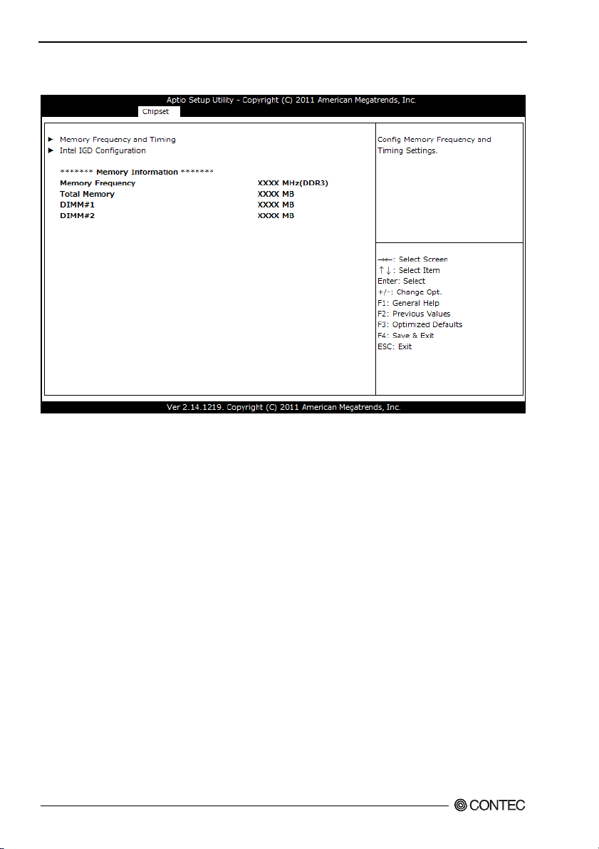
5. BIOS Setup
Memory Frequency and Timing
Figure 5.15 Memory Frequency and Timing
Settings that can be configured in the Memory Frequency and Timing are described in the table below.
Table 5.13 Memory Frequency and Timing
Item Options Description
MRC Fast Boot
Max TOLUD
Disabled
Enabled
Dynamic
1 GB
1.25 GB
1.5 GB
1.75 GB
2 GB
2.25 GB
2.5 GB
2.75 GB
3 GB
3.25 GB
Enable or disable MRC fast boot.
Do not change this setting.
Sets the maximum TOLUD size.
Do not change this setting.
BX-955Sx Series User’s manual
49
Page 57

5. BIOS Setup
Intel IGD Configuration
Figure 5.16 Intel IGD Configuration
Settings that can be configured in the Intel IGD Configuration are described in the table below.
Table 5.14 Intel IGD Configuration
Item Options Description
Selects the VBIOS setting. To use Windows
7, set this to "Win 7," to use another OS, set
VBIOS Select for OS
Boot Display Type
Win7
Other
CRT
DVI
CRT+DVI
this to "Other".
* When the BIOS default settings are
loaded, this is set to "Win 7".
* After you install the OS, do not change
this setting.
Selects the display for the BIOS SETUP
screen. This is set as shown below when
the product is shipped.
BX-955SD-DC6000 : CRT+DVI
BX-955S-DC6311 : CRT
BX-955SD-DC6311 : DVI
BX-955SD-DC6312 : CRT+DVI
* When the BIOS default settings are
loaded, this is set to "CRT + DVI".
BX-955Sx Series User’s manual
50
Page 58
5. BIOS Setup
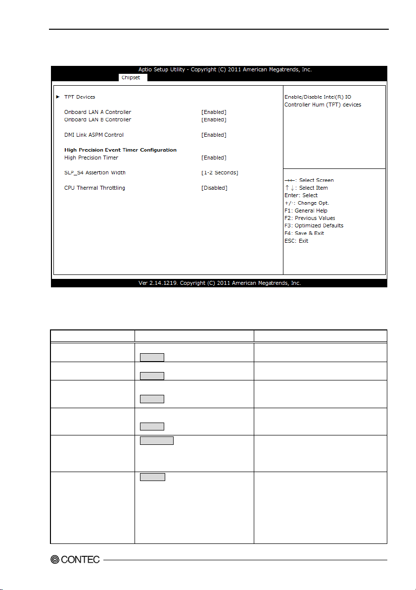
South Bridge
Figure 5.17 South Bridge
Settings that can be configured in the South Bridge are described in the table below.
Table 5.15 South Bridge
Item Options Description
Onboard LAN A
Controller
Onboard LAN B
Controller
DMI Link ASPM Controll
High Precision Timer
SLP_S4 Assertion Width
CPU Thermal Throttling
Disabled
Enabled
Disabled
Enabled
Disabled
Enabled
Disabled
Enabled
1-2 Seconds
2-3 Seconds
3-4 Seconds
4-5 Seconds
Disabled
12.5%
25%
37.5%
50%
62.5%
75%
87.5%
Enable / Disable Onboard LAN A
Controller.
Enable / Disable Onboard LAN B
Controller.
Enables or disables the ASPM control with
the DMI link.
Normally do not change this setting.
Enables or disables the high-precision
event timer.
Normally do not change this setting.
Sets the minimum assertion time of the S4
signal.
Normally do not change this setting.
Sets the clock reduction rate when the CPU
temperature increases.
BX-955Sx Series User’s manual
51
Page 59

5. BIOS Setup
Item Options Description
Disabled
50 C/122 F
55 C/131 F
Threshold Temperature
60 C/140 F
65 C/149 F
70 C/158 F
75 C/167 F
70 C 176 F
The following sub items are available:
TPT Devices
Use this menu to specify Intel IO Controller Hub(TPT) settings.
Sets the temperature at which to start
reducing the clock when the CPU
temperature increases.
BX-955Sx Series User’s manual
52
Page 60

5. BIOS Setup
TPT Devices
Figure 5.18 TPT Devices
Settings that can be configured in the TPT Devices are described in the table below.
Table 5.16 TPT Devices
Item Options Description
Azalia Controller
Azalia Vci Enable
Select USB Mode
Disabled
HD Audio
Disabled
Enabled
By Controllers
By Ports onry
Enables or disables the Azalia sound
controller. Normally do not change this
setting.
Enables or disables the Azalia Vci.
Normally do not change this setting.
Selects how to specify the USB port to use.
Normally do not change this setting.
By Controllers :
The USB port to use is specified by the
UHCI controllers.
- External USB port
UHCI#1
Port 0
UCCI#3, #4 : Internal USB port
By Ports Only : The USB port to use is
specified by its port number.
Port 2
Port 1
BX-955Sx Series User’s manual
UCHI#2
Port 3
53
Page 61

5. BIOS Setup
Item Options Description
UHCI #1 (ports 0 and 1)
UHCI #2 (ports 2 and 3)
UHCI #3 (ports 4 and 5)
UHCI #4 (ports 6 and 7)
USB Function
USB 2.0(EHCI) Support
SMBus Controller
Disabled
Enabled
Disabled
Enabled
Disabled
Enabled
Disabled
Enabled
Disabled
1 USB Ports
2 USB Ports
3 USB Ports
4 USB Ports
5 USB Ports
6 USB Ports
7 USB Ports
8 USB Ports
Disabled
Enabled
Disabled
Enabled
(When the USB mode is set to "By
Controllers".)
Enables or disables USB ports 0 and 1.
Normally do not change this setting.
(When the USB mode is set to "By
Controllers".)
Enables or disables USB ports 2 and 3.
Normally do not change this setting.
(When the USB mode is set to "By
Controllers".)
Enables or disables USB ports 4 and 5.
Normally do not change this setting.
(When the USB mode is set to "By
Controllers".)
Enables or disables USB ports 6 and 7.
Normally do not change this setting.
(When the USB mode is set to " By Ports
only".)
Sets USB function.
1 - 4 : External USB port
5 - 8 : Internal USB port
Enable or Disable USB 2.0 (EHCI) Support.
Normally do not change this setting.
Enable or Disable SMBus Controller.
Normally do not change this setting.
BX-955Sx Series User’s manual
54
Page 62
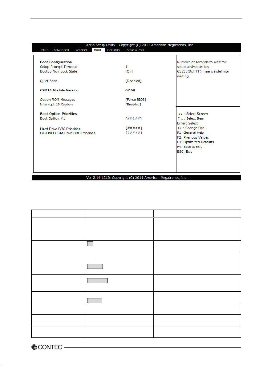
5. BIOS Setup
Boot
Figure 5.19 Boot menu
Use this menu to specify settings related to system startup. The following items are available:
Table 5.17 Boot
Item Options Description
Setup Prompt Timeout 1 - 65535
Bootup NumLock State
Quiet Boot
Option ROM Messages
Interrupt 19 Capture
Boot Option #x
CD/DVD ROM Drive BBS
Priorities
Hard Drive BBS
Priorities
On
Off
Enabled
Disabled
Force BIOS
Keep Current
Disabled
Enabled
XXXXXXXXX (Specify an arbitrary
device.)
XXXXXXXXX (Specify an arbitrary
device.)
XXXXXXXXX (Specify an arbitrary
device.)
BX-955Sx Series User’s manual
Sets the timeout time (in seconds) after which
the system switches to the BIOS setup screen.
Set this to "65535" to make the system wait
until it receives key input.
Sets the initial state of the Num Lock key on
the USB keyboard.
Enables or disables Quiet Boot option
If you set this to "Enabled," information will
not be displayed, which shortens the time
that it takes the system to start.
Sets the display of the BIOS message that
appears when you connect an optional ROM.
Normally do not change this setting.
Enables or disables optional ROM interrupts.
Normally do not change this setting.
Sets the order of bootable devices that are
connected.
Specifies the start order of the connected CD
or DVD drives.
Specifies the start order of the connected
CFast or USB removable drives.
55
Page 63
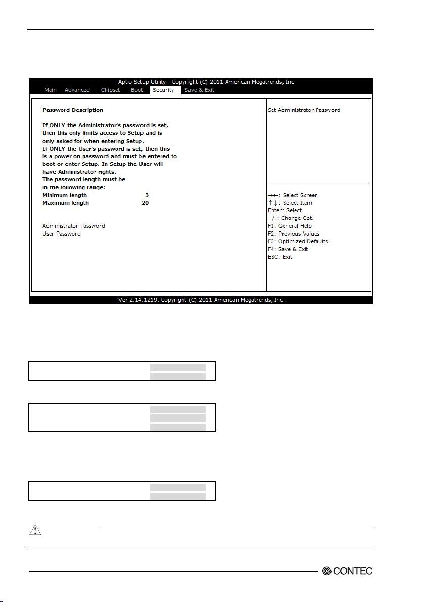
5. BIOS Setup
Security
Use this menu to configure system security settings.
Figure 5.20 Security menu
The following items are available:
Administrator Password
When you press <Enter> on this item, you are required to input the password as below.
Create New Password [**** ]
Confirm New Password [**** ]
Enter a password of between 3 and 20 characters twice.
To nullify the password, go to the Administrator Password Input Screen again.
Enter Current Password [**** ]
Create New Password [ ]
Confirm New Password [ ]
When you input old password in the initial item and then press <Enter> by inputting nothing to the new
password item, the password will be nullified.
User Password
When you press <Enter> on this item, you are required to input the password as below.
Create New Password [**** ]
Confirm New Password [**** ]
Enter a password of between 3 and 20 characters twice.
Follow the same procedure as Administrator Password to nullify the password.
CAUTION
If you forget the password, the product will have to be repaired.
BX-955Sx Series User’s manual
56
Page 64

5. BIOS Setup
Save & Exit
Use this menu to load/save settings changes, and exit the setup menu.
Figure 5.21 Save & Exit menu
The following items are available:
Save Changes and Exit
When you press <Enter> on this item you get a confirmation dialog box with a message similar to:
Save & Exit Setup
Save configuration and exit?
[Yes] [No]
Select "[Yes]" to record the selections that you made on the menu to the FLASH ROM. Depending on
the changed items, the system may restart. The next time the computer is booted, the BIOS configures
the system based on the configuration stored in FLASH ROM.
Pressing [No], it will return to setup menu.
Discard Changes and Exit
When you press <Enter> on this item you get a confirmation dialog box with a message similar to:
Exit Without Saving
Quit without saving?
[Yes] [No]
Pressing [Yes] continues to boot the system without saving any changes made in FLASH ROM.
Pressing [No] returns to the setup menu without records in FLASH ROM.
BX-955Sx Series User’s manual
57
Page 65

5. BIOS Setup
Save Changes and Reset
When you press <Enter> on this item you get a confirmation dialog box with a message similar to:
Save & Reset
Save configuration and reset?
[Yes] [No]
Pressing [Yes] saves any changes made in FLASH ROM and reboots the system. The next time the
computer is booted, the BIOS configures the system based on the configuration stored in FLASH ROM.
Pressing [No], it will return to setup menu.
Discard Changes and Reset
When you press <Enter> on this item you get a confirmation dialog box with a message similar to:
Reset Without Saving
Reset without saving?
[Yes] [No]
Pressing [Yes] reboots the system without saving an y changes made in FLASH ROM.
Pressing [No] returns to the setup menu without records in FLASH ROM.
Save Changes
When you press <Enter> on this item you get a confirmation dialog box with a message similar to:
Save Setup Values
Save Configuration?
[Yes] [No]
Pressing [Yes] saves any changes made in FLASH ROM and takes you back to the setup menu.
Pressing [No], it will return to setup menu.
Discard Changes
When you press <Enter> on this item you get a confirmation dialog box with a message similar to:
Load Previos Values
Load Previous Values?
[Yes] [No]
Pressing [Yes] discards any changes made and takes you back to the setup menu after loading the
previous settings saved in FLASH ROM.
Pressing [No], it will return to setup menu.
Restore Defaults
When you press <Enter> on this item you get a confirmation dialog box with a message similar to:
Load Optimized Defaults
Load Optimized Defaults?
[Yes] [No]
Select "[Yes]" to load the default values of the factory settings to use in operating the system. This
setting will not take effect until you save to FLASH ROM.
Pressing [No] returns to the setup menu without loading.
BX-955Sx Series User’s manual
58
Page 66
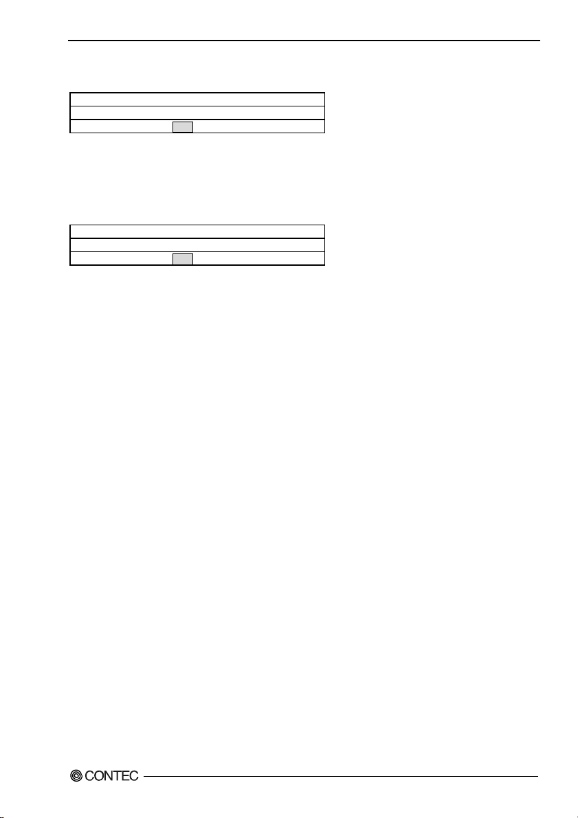
5. BIOS Setup
Save as User Defaults
When you press <Enter> on this item you get a confirmation dialog box with a message similar to:
Save Values as User Defaults
Save Configuration?
[Yes] [No]
Pressing [Yes] saves the current settings as the user default settings in FLASH ROM and takes you back
to the setup menu.
Pressing [No], it will return to setup menu.
Restore User Defaults
When you press <Enter> on this item you get a confirmation dialog box with a message similar to:
Restore User Defaults
Restore User Defaults?
[Yes] [No]
Pressing [Yes] loads the settings saved in FLASH ROM as the user default settings and takes you back
to the setup menu. This setting is not reflected to the FLASH ROM until you save it.
Pressing [No], it will return to setup menu.
Boot Override
Using the cursor to select the device that you want to start and pressing <Enter> key directly boots the
selected device regardless of the order set in the Boot menu.
POST Beep
Currently there are two kinds of beep codes in BIOS. This code indicates that a video error has occurred
and the BIOS cannot initialize the video screen to display any additional information. This beep code
consists of a single long beep followed by two short beeps. The other code indicates that your DRAM
error has occurred. This beep code consists of a single long beep repeatedly.
BX-955Sx Series User’s manual
59
Page 67

5. BIOS Setup
Position and Settings of the ROM Clear Switches
If the BIOS settings cause unexpected system start errors, you can set the ROM clear switches and start
the system to disable the BIOS settings and start the system.
During normal operation, leave the ROM clear switches in their factory default settings (HSW2-1 is in
the ON position).
CAUTION
This product's heat sink may reach high temperatures. Touching this product immediately after it
is turned off may lead to burns. Wait until the product has cooled down before you configure the
switch settings.
(1) Remove the rear surface cover from the product.
(Number of screws Cover : 3)
When you remove the rear surface cover, ther ROM clear dip switches (HSW2 and HSW3) are
arranged as shown in the following figure.
HSW3 HSW2
ON
ON
OFF
12ON12
HSW1
HSW3
HSW1
Figure 5.22 ROM clear jumper positions when the cover and heat sink are removed
(2) Set switch 1 of ROM clear dip switch HSW2 to the OFF position.
(3) Reattach the cover to the product. Do not apply excessive force when tightening the screws.
(4) Turn the power on. After you hear a beep, turn the power off.
(6) Remove the cover, and then return switch 1 of ROM clear dip switch HSW2 to the ON position.
(7) Attach the cover.
CAUTION
- If you tighten the screws with a tightening torque greater than that specified, the screw holes may
be damaged.
The appropriate tightening torque for the screws is 1 to 1.5 kgf•cm.
- Pay attention to the following points when removing the screws that are used to fix the rear surface
cover in place.
Performing the operations incorrectly may damage the screw holes.
- When removing the cover, use a screwdriver with the following type of tip.
Cover : (+)No.0
- When removing the cover screws, do not use an electronic screwdriver.
BX-955Sx Series User’s manual
60
Page 68

6. Appendix
6. Appendix
Memory Map
Table 6.1. Memory Map
Memory Segments Comments
00000h - 9FFFh 0 - 640K DOS Region
A0000h – BFFFFh Video Buffer
B0000h - B7FFFh Monochrome Adapter range
C0000h – CFFFFh Video BIOS
D0000h – DFFFFh Expansion Area
E0000h – EFFFFh Extended System BIOS Area
F0000h – FFFFFh System BIOS Area
100000h – FFFFFFFFh Extended Memory Area
100000h - Top of Main Memory Main DRAM Address Range
Top of Main Memory Extended SMRAM Address Range
Top of Main Memory To 4GB PCI Memory Address Range
FEC0000h - FECFFFFFh, APIC Configuration space
FFE00000h – FFFFFFFFh High BIOS Area
BX-955Sx Series User’s manual
61
Page 69

6. Appendix
I/O Port Addresses
Table 6.2. I/O Port Addresses < 1 / 2 >
Address Size Description
0000 - 001F 32 bytes DMA controller
0020 - 0021 2 bytes Interrupt controller
0024 - 0025 2 bytes Interrupt controller
0028 - 0029 2 bytes Interrupt controller
002C – 002D 2 bytes Interrupt controller
002E – 002F 2 bytes LPC SIO
0030 – 0031 2 bytes Interrupt controller
0034 - 0035 2 bytes Interrupt controller
0038 - 0039 2 bytes Interrupt controller
003C – 003D 2 bytes Interrupt controller
0040 - 0043 4 bytes Timer / Counter
004E – 004F 2 bytes LPC SIO
0050 - 0053 4 bytes Timer / Counter
0060 1 byte Kerboard controller
0061 1 byte NMI controller
0062 1 byte Microcontroller
0064 1 byte Kerboard controller
0066 1 byte Microcontroller
0070 - 0077 8 bytes NMI / real time clock controller
0080 – 0091 18 bytes DMA controller / LPC / PCI
0092 1 byte Reset generator
0093 – 009F 13 bytes DMA controller
00A0 – 00A1 2 bytes Interrupt controller
00A4 – 00A5 2 bytes Interrupt controller
00A8 – 00A9 2 bytes Interrupt controller
00AC – 00AD 2 bytes Interrupt controller
00B0 – 00B1 2 bytes Interrupt controller
00B2 – 00B3 2 bytes Power management
00B4 – 00B5 2 bytes Interrupt controller
00B8 – 00B9 2 bytes Interrupt controller
00BC – 00BD 2 bytes Interrupt controller
00C0 – 00DF 32 bytes DMA controller
00F0 1 byte Interrupt controller
0170 - 0177 8 bytes IDE / SATA controller, PCI
01F0 – 01F7 8 bytes IDE / SATA controller, PCI
0200 – 020F 16 bytes Reserved
0260 - 0267 8 bytes Reserved
0268 – 026F 8 bytes Reserved
0270 – 0277 8 bytes Reserved
0278 – 027F 8 bytes Reserved
02F8 – 02FF 8 bytes SERIAL B
0376 1 byte IDE / SATA controller, PCI
03B0 – 03BB 13 bytes Graphics
03C0 – 03DF 32 bytes Graphics
BX-955Sx Series User’s manual
62
Page 70

6. Appendix
Table 6.2. I/O Port Addresses < 2 / 2 >
Address Size Description
03F6 1 byte IDE / SATA controller, PCI
03F8 – 03FF 8 bytes SERIAL A
0400 – 043F 64 bytes Power management
04D0 – 04D1 2 bytes Interrupt controller
0500 – 053F 64 bytes Reserved (GPIO)
0CF9 1 byte Reset generator
0D00 – 0FFFF 62208 bytes PCI bus
Interrupt Level List
Table 6.3. Hardware Interrupt Levels (Factory Settings)
Type 8259 Priority Description Vector
NMI High -I/O CHK 02H
IRQ0 MASTER ↑ Timer 0 08H
IRQ1 “ ⏐ Reserved 09H
IRQ2 “ ⏐ Interrupt Controller 2 (Slave) 0AH
IRQ8 SLAVE ⏐ Realtime Clock 70H
IRQ9 “ ⏐ Reserved 71H
IRQ10 “ ⏐ Reserved 72H
IRQ11 “ ⏐ Reserved 73H
IRQ12 “ ⏐ Reserved 74H
IRQ13 “ ⏐ Co-processor 75H
IRQ14 “ ⏐ Not used (Useable for user) 76H
IRQ15 “ ⏐ Not used (Useable for user) 77H
IRQ3 MASTER ⏐ Serial port B(COM B) 0BH
IRQ4 “ ⏐ Serial port A(COM A) 0CH
IRQ5 “ ⏐ System reserved 0DH
IRQ6 “ ↓ Not used (Useable for user) 0EH
IRQ7 “ Low System reserved 0FH
BX-955Sx Series User’s manual
63
Page 71

6. Appendix
POST Codes
Table 6.4. POST Codes < 1 / 3 >
POST
(hex)
< Security (SEC) phase >
1h Power on. Reset type detection (software / hardware)
2h AP initialization before microcode loading
3h North Bridge initialization before microcode loading
4h South Bridge initialization before microcode loading
5h OEM initialization before microcode loading
6h Microcode loading
7h AP initialization after microcode loading
8h North Bridge initialization after microcode loading
9h South Bridge initialization after microcode loading
Ah OEM initialization after microcode loading
Bh Cache initialization
< Pre-EFI Initialization (PEI) phase >
10h PEI Core is started
11h Pre-memory CPU initialization is started
12h – 14h Pre-memory CPU initialization (CPU module specific)
15h Pre-memory North Bridge initialization is started
16h – 18h Pre-Memory North Bridge initialization (North Bridge module specific)
19h Pre-memory South Bridge initialization is started
1Ah – 1Ch Pre-memory South Bridge initialization (South Bridge module specific)
1Dh – 2Ah OEM pre-memory initialization codes
2Bh Memory initialization. Serial Presence Detect (SPD) data reading
2Ch Memory initialization. Memory presence detection
2Dh Memory initialization. Programming memory timing information
2Eh Memory initialization. Configuring memory
2Fh Memory initialization (other).
30h Reserved for ASL (see ASL Status Codes section below)
31h Memory Installed
32h CPU post-memory initialization is started
33h CPU post-memory initialization. Cache initialization
34h CPU post-memory initialization. Application Processor(s) (AP) initialization
35h CPU post-memory initialization. Boot Strap Processor (BSP) selection
37h CPU post-memory initialization. System Management Mode (SMM) initialization
38h Post-Memory North Bridge initialization is started
39h – 3Ah Post-Memory North Bridge initialization (North Bridge module specific)
3Bh Post-Memory South Bridge initialization is started
3Ch – 3Eh Post-Memory South Bridge initialization (South Bridge module specific)
3Fh – 4Eh OEM post memory initialization codes
4Fh DXE IPL is started
< Driver Execution Environment (DXE) phase >
60h DXE Core is started
61h NVRAM initialization
62h Installation of the South Bridge Runtime Services
63h CPU DXE initialization is started
64h-67h CPU DXE initialization (CPU module specific)
68h PCI host bridge initialization
Description
BX-955Sx Series User’s manual
64
Page 72

6. Appendix
Table 6.4. POST Codes < 2 / 3 >
POST
(hex)
69h North Bridge DXE initialization is started
6Ah North Bridge DXE SMM initialization is started
6Bh - 6Fh North Bridge DXE initialization (North Bridge module specific)
70h South Bridge DXE initialization is started
71h South Bridge DXE SMM initialization is started
72h South Bridge devices initialization
73h – 77h South Bridge DXE Initialization (South Bridge module specific)
78h ACPI module initialization
79h CSM initialization
7Ah – 7Fh Reserved for future AMI DXE codes
80h – 8Fh OEM DXE initialization codes
90h Boot Device Selection (BDS) phase
91h Driver connecting is started
92h PCI Bus initialization is started
93h PCI Bus Hot Plug Controller Initialization
94h PCI Bus Enumeration
95h PCI Bus Request Resources
96h PCI Bus Assign Resources
97h Console Output devices connect
98h Console Input devices connect
99h Super IO Initialization
9Ah USB initialization is started
9Bh USB Reset
9Ch USB Detect
9Dh USB Enable
9Eh – 9Fh Reserved for future AMI codes
A0h IDE initialization is started
A1h IDE Reset
A2h IDE Detect
A3h IDE Enable
A4h SCSI initialization is started
A5h SCSI Reset
A6h SCSI Detect
A7h SCSI Enable
A8h Setup Verifying Password
A9h Start of Setup
AAh Reserved for ASL (see ASL Status Codes section below)
ABh Setup Input Wait
ACh Reserved for ASL (see ASL Status Codes section below)
ADh Ready To Boot event
AEh Legacy Boot event
AFh Exit Boot Services event
B0h Runtime Set Virtual Address MAP Begin
B1h Runtime Set Virtual Address MAP End
B2h Legacy Option ROM Initialization
B3h System Reset
B4h USB hot plug
B5h PCI bus hot plug
B6h Clean-up of NVRAM
B7h Configuration Reset (reset of NVRAM settings)
B8h - BFh Reserved for future AMI codes
C0h - CFh OEM BDS initialization codes
Description
BX-955Sx Series User’s manual
65
Page 73

6. Appendix
Table 6.4. POST Codes < 3 / 3 >
POST
(hex)
ACPI/ASL Checkpoints
01h System is entering S1 sleep state
02h System is entering S2 sleep state
03h System is entering S3 sleep state
04h System is entering S4 sleep state
05h System is entering S5 sleep state
10h System is waking up from the S1 sleep state
20h System is waking up from the S2 sleep state
30h System is waking up from the S3 sleep state
40h System is waking up from the S4 sleep state
ACh System has transitioned into ACPI mode. Interrupt controller is in PIC mode.
AAh System has transitioned into ACPI mode. Interrupt controller is in APIC mode.
Description
SERIAL I/O Address and Register Function
The following table lists the I/O addresses in case of SERIAL A.
Table 6.5. I/O Address
I/O address DLAB Read/Write Register
Transmitter holding register
03F8H
03FAH X R
03FBH X W
03FCH X W
03FDH X R
03FEH X R
03FFH X R/W
DLAB (Divisor Latch Access Bit) : The value in bit 7 of the line control register.
0
1 W
1 W
0 W
W
Receive buffer register
R
Divisor latch register (LSB)
Divisor latch register (MSB)
Interrupt enable register
Interrupt ID register
Line control register
Modem control register
Line status register
Modem status register
Scratch register
THR
RBR
DLL
DLM 03F9H
IER
IIR
LCR
MCR
LSR
MSR
SCR
BX-955Sx Series User’s manual
66
Page 74
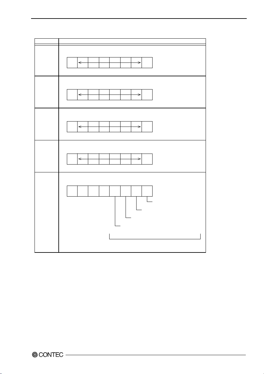
6. Appendix
Table 6.6. Function of Each Register < 1 / 4 >
I/O address Description
03F8H
03F8H
03F8H
03F9H
03F9H
THR: Transmitter Holding Register [DLAB=0]
D7 D6 D5 D4 D3 D2 D1 D0
bit7
MSB
Register dedicated to write transmitted data to
RBR: Reciever Buffer Register [DLAB=O]
D7 D6 D5 D4 D3 D2 D1 D0
bit7
MSB
Register dedicated to read received data from
DLL: Divisor Latch (LSB) [DLAB=1]
D7 D6 D5 D4 D3 D2 D1 D0
bit7
MSB
Baud rate setting register (LSB)
DLH: Divisor Latch (MSB) [DLAB=1]
D7 D6 D5 D4 D3 D2 D1 D0
bit7
MSB
Baud rate setting register (MSB)
IER: Interrupt Enable Register [DLAB=0]
D7 D6 D5 D4 D3 D2 D1 D0
0
000EMSELSI
ETHREI
Receiver line status
Interrupt enable
Modem status interrupt enable
[Always used at 0.]
bit0
LSB
bit0
LSB
bit0
LSB
bit0
LSB
ERDAI
Received data
Interrupt enable
Received data register empty
Interrupt enable
BX-955Sx Series User’s manual
1: Enable interrupt
0: Disable interrupt
67
Page 75
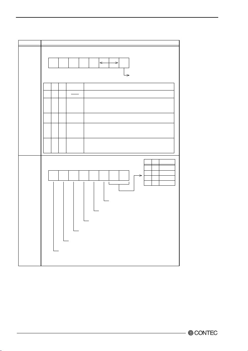
6. Appendix
Table 6.6. Function of Each Register < 2 / 4 >
I/O address Description
03FAH
IIR : Interrupt Identification Register
D7 D6 D5 D4 D3 D2 D1 D0
00000
Interrupt details
bit20bit10bit01Priority Description
Interrupts are not generated.
110
100
010
000
Generated by overrun, parity, framing error or break
1 (high)
interrupt.
Cleared when the line status register is read.
Generated when the receive buffer register is ready.
2
Cleared when the receiving buffer is read.
Generated when the transmitter holding register is
3
empty. Cleared when the IIR is read or when
transmitted data is written to THR.
Modem status interrupt is generated.
4 (low)
(CTS, DSR, RI, CD)
Cleared when the modem status register is read.
1: Do not generate interrupts
0: Generate interrupts
03FBH
LCR : Line Contror Regester
D7 D6 D5 D4 D3 D2 D1 D0
0 : 1 STOP bit
1 : 1.5 STOP bits at 5-bit length
2 STOP bits at 6-, 7-, or 8-bit length
0 : Disable parity
1 : Enable parity
0 : Odd parity
1 : Even parity
0 : Disable stick parity
1 : Enable stick parity
0 : Break signal off
1 : Send break signal
DLAB (Divisor Latch Access Bit)
In order to access the divisor latch regist er, you need to set the bit
to 1. To access another register, set the bit to 0.
D1
D0
Bit table
0
0
0
1
1
5
1
6
0
7
1
8
BX-955Sx Series User’s manual
68
Page 76

6. Appendix
Table 6.6. Function of Each Register < 3 / 4 >
I/O address Description
03FCH
03FDH
MCR: Modem Control Register
D7 D6 D5 D4 D3 D2 D1 D0
000Loop
LSR: Line Status Regester
D7 D6 D5 D4 D3 D2 D1 D0
0 TEMT
THRE
Tra ns mi tter em pt y
(Set to 1 when both transmitter holding register and
transmitter shift register are empty.)
IRQ X RTS DTR
Interrupt control bit
0 : Disable
1 : Enable
Diagnostic local loop-back test
0 : Disable
1 : Enable
BI FE PE OE DR
Framing error (1 for occurrence of an error)
Break interrupt (1 for detection of break state)
Transmitter holding register empty
(1 for transmission buffer being empty)
DTR
0 : Inactive
[HIGH]
1 : Active
RTS
Overrun error
(1 for occurrence of an error)
Parity error (1 for occurrence of an error)
[LOW]
0 : Inactive
[HIGH]
1 : Active
[LOW]
Data ready
(1 for existence of received data)
BX-955Sx Series User’s manual
69
Page 77
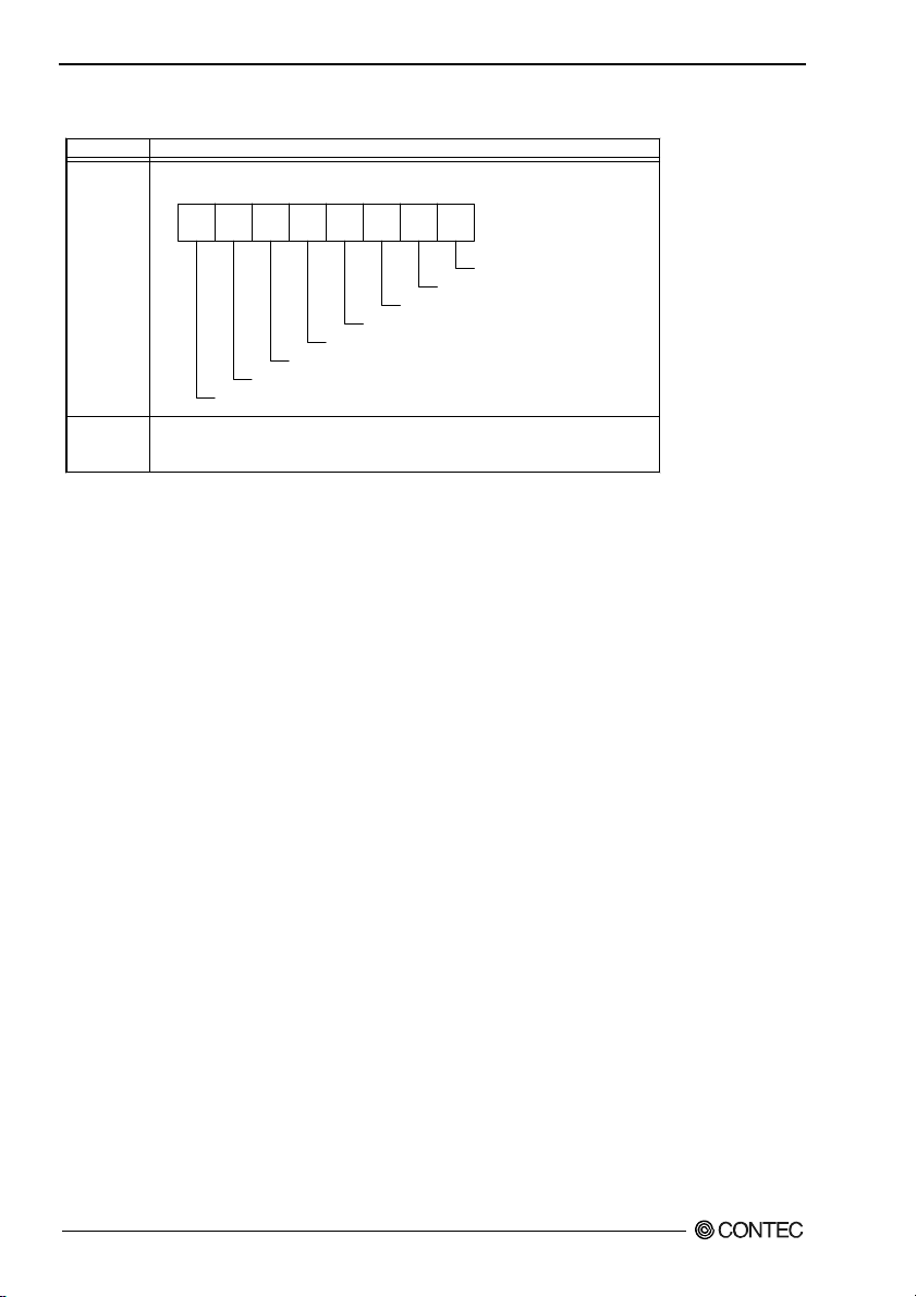
6. Appendix
Table 6.6. Function of Each Register < 4 / 4 >
I/O address Description
03FEH
03FFH
MSR : Modem Status Register
D7 D6 D5 D4 D3 D2 D1 D0
DSR
DDCD
CTS
DDSR
TERI
Trailing edge RI
Delta data carrier detect
DCD RI DSR CTS
RI
DCD
SCR : Scratchpad Register
This is an 8-bit, readable/writable register which is available to the user to
allow data to be saved temporarily.
DCTS
Delta CTS
Delta DSR
BX-955Sx Series User’s manual
70
Page 78

6. Appendix
Baud Rate Settings
A baud rate is set by software by dividing the clock input (1.8432MHz). The baud rate in terms of
hardware can be set to a maximum of 115,200 bps for SERIAL A, B, C, D. The baud rates available in
practice depend on the operating environment (cable, software, etc.). The table below lists typical baud
rates and their respective values to be written to the divisor latch register (LSB, MSB).
Table 6.7. Baud Rate Settings
Baud rate to be set
50 2304 ---
75 1536 ---
110 1047 0.026
134.5 857 0.058
150 768 ---
300 384 ---
600 192 ---
1200 96 ---
1800 64 ---
2000 58 0.69
2400 48 ---
3600 32 ---
4800 24 ---
7200 16 ---
9600 12 ---
14400 8 ---
19200 6 ---
28800 4 ---
38400 3 ---
57600 2 ---
76800 --- ---
115200 1 ---
153600 --- ---
230400 --- ---
Example: To set 9,600 bps, write "00" to the (MSB) divisor latch register and "12 (decimal)" to the (LSB) divisor latch
register.
SERIAL A, B, C, D
Clock input (1.8432MHz)
Value to be set
in the divisor register
(Decimal)
Setting error (%)
BX-955Sx Series User’s manual
71
Page 79
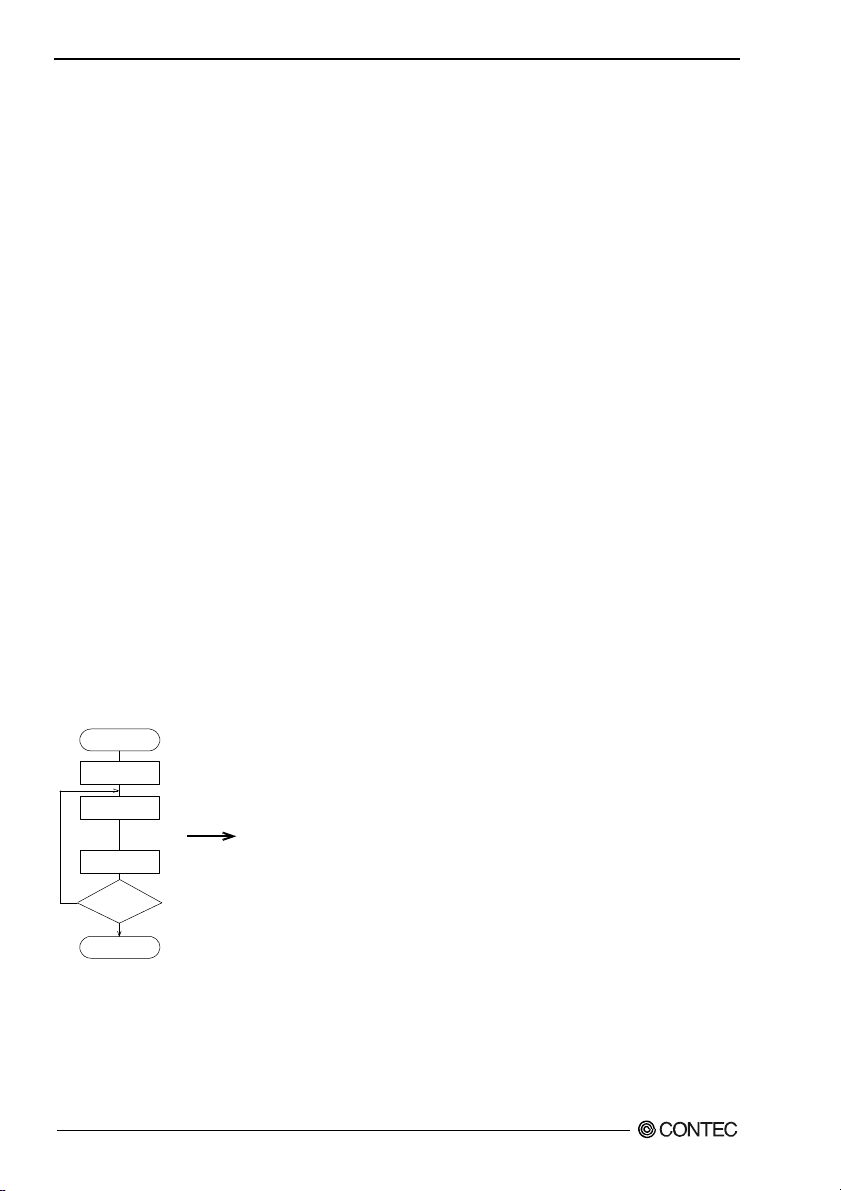
6. Appendix
Watch-Dog-Timer
The watchdog timer serves as a safeguard against possible system lock-up in your industrial computer
system. In most industrial environments, there are heavy equipment, generators, high-voltage power
lines, or power drops that have adverse effects on your computer system. For instance, when a power
drop occurs, it could cause the CPU to come to a halt state or enter into an infinite loop, resulting in a
system lock-up.
The application software created by user with the watchdog timer enabled, a RESET automatically
generated unless the software periodically triggers the timer within the setting time-out interval. That is,
while the system gets hung up, the running program can’t trigger the timer periodically. The timer will
generate a reset signal to reboot the system.
This feature allows a running program to restart in an orderly way when a power glitch or any abnormal
condition occurs.
The watchdog timer comes with 255-level time-out interval, 1 - 255 seconds per interval, which can be
adjusted by software setting. There is a tolerance of 2 second for this time-out interval. To maintain the
normal system operation, trigger the timer periodically by the user-created program in consideration of
the tolerance.
Ex.) If the time-out interval is set to 30 seconds, the user-created program must retrigger the watchdog
timer before 28 seconds will have elapsed in consideration of the tolerance. If the program failed to
retrigger the timer (if 28 - 32 seconds have elapsed), the system will automatically reboot.
The I/O port is defined at address 2e/2fH. You can trigger/enable disable the timer by writing address
2e/2fH.
Here is an example for flow chart and programming how to use the watch-dog-timer.
(1) Example flow chart
START
WDT Initial
WDT Start
WDT Stop
Yes
WDT
Restart?
* It is also possible not to perform [WDT Stop] instead of performing [WDT Stop] to [WDT Start], but to perform
[WDT Start] continuously at the time of a re-start.
BX-955Sx Series User’s manual
72
}
When performing the re-start of WD T, it repeats [WDT Start] and [WDT Stop].
No
END
If [WDT Stop] is not performed within the limit time set up
by [WDT Start], system reset occurs.
Page 80

6. Appendix
(2) Example programming
The following example is written in Intel8086 assembly language.
;===============
;<WDT Initial>
;===============
;------------------------------------------;Enter the extended function mode
;------------------------------------------MOV DX,2EH
MOV AL,87H
OUT DX,AL
OUT DX,AL
;----------------------------------;Set WDT function at pin89
;----------------------------------MOV DX,2EH
MOV AL,2BH
OUT DX,AL
MOV DX,2FH
MOV AL,0DH
OUT DX,AL
;-----------------------------------------------;Select logical device WDT(number 8)
;------------------------------------------------MOV DX,2EH
MOV AL,07H
OUT DX,AL
MOV DX,2FH
MOV AL,08H
OUT DX,AL
;--------------------------------------------------;Activate logical device WDT(number 8)
;--------------------------------------------------MOV DX,2EH
MOV AL,30H
OUT DX,AL
MOV DX,2FH
MOV AL,01H
OUT DX,AL
;----------------------------------;Set timer unit : second
;----------------------------------MOV DX,2EH
MOV AL,F5H
OUT DX,AL
MOV DX,2FH
BX-955Sx Series User’s manual
73
Page 81

6. Appendix
MOV AL,00H
OUT DX,AL
;-----------------------------------------;Exit the extended function mode
;-----------------------------------------MOV DX,2EH
MOV AL,AAH
OUT DX,AL
;================================
;<WDT START : counter set and a start >
;================================
;--------------------------------------------;Enter the extended function mode
;--------------------------------------------MOV DX,2EH
MOV AL,87H
OUT DX,AL
OUT DX,AL
;-----------------------------------------------;Select logical device WDT(number 8)
;-----------------------------------------------MOV DX,2EH
MOV AL,07H
OUT DX,AL
MOV DX,2FH
MOV AL,08H
OUT DX,AL
;-----------------------------------------------------;Set time of WDT and start to count down
;-----------------------------------------------------MOV DX,2EH
MOV AL,F6H
OUT DX,AL
MOV DX,2FH
;------------------------------------------------------ ---------------------------;The data of an example is 15 seconds.(01H=1sec.- FFH=255sec.)
MOV AL,0FH ; 0FH = 15Sec.
;------------------------------------------------------ ----------------------------OUT DX,AL
;----------------------------------;Exit the extended function mode
;----------------------------------MOV DX,2EH
MOV AL,AAH
OUT DX,AL
BX-955Sx Series User’s manual
74
Page 82

6. Appendix
;==============
;<WDT STOP>
;==============
;----------------------------------;Enter the extended function mode
;----------------------------------MOV DX,2EH
MOV AL,87H
OUT DX,AL
OUT DX,AL
;----------------------------------;Select logical device WDT(number 8)
;----------------------------------MOV DX,2EH
MOV AL,07H
OUT DX,AL
MOV DX,2FH
MOV AL,08H
OUT DX,AL
;----------------------------------;Stop count down of WDT
;----------------------------------MOV DX,2EH
MOV AL,F6H
OUT DX,AL
MOV DX,2FH
;----------------------------------;The data of 00H is stop WDT
MOV AL,00H
;----------------------------------OUT DX,AL
;----------------------------------;Exit the extended function mode
;----------------------------------MOV DX,2EH
MOV AL,AAH
OUT DX,AL
CAUTION
The timer’s intervals have a tolerance of ±2 seconds.
BX-955Sx Series User’s manual
75
Page 83

6. Appendix
Status LED
The operation of the status LED can be controlled from user applications.
The following is a sample program created in an MS-DOS environment with MSC version 8.03.
The status LED blinks once per second for approximately 10 seconds.
#include <stdio.h>
#include <time.h>
#include <dos.h>
#include <io.h>
#define IDX 0x2e
#define DAT IDX+1
#define IOWAIT outp( 0xed, 0x 00 )
/* READ WD83627 CR */
int get_reg( int adr )
{
IOWAIT;
outp( IDX, adr );
IOWAIT;
return inp( DAT );
}
/* WRITE WD83627 CR */
void set_reg( int adr, int dat )
{
IOWAIT;
outp( IDX, adr );
IOWAIT;
outp( DAT, dat );
}
/* WD83627 SET LOGICAL DEV */
void set_ldev( int dev )
{
set_reg( 7, dev );
}
/* OPEN WD83627 CR */
void open_dev( void )
{
IOWAIT;
outp( IDX, 0x87 );
IOWAIT;
BX-955Sx Series User’s manual
76
Page 84

6. Appendix
outp( IDX, 0x87 );
}
/* CLOSE WD83627 CR */
void close_dev( void )
{
IOWAIT;
outp( IDX, 0xaa );
}
int main( int argc, char *argv[] )
{
time_t otm,rtm, rtm2;
open_dev();
set_ldev( 9 );
set_reg( 0x30, get_reg(0x30) | 0x08 ); // Enable GPIO5x
set_reg( 0xe0, get_reg(0xe0) & 0xdf ); // GPIO55(SLED) output
set_reg( 0xe1, get_reg(0xe1) & 0xdf ); // GPIO55(SLED) OFF
otm=rtm=rtm2=time(&rtm);
while( (otm+10)>rtm ){
rtm=time(&rtm);
if( rtm != rtm2 ){
rtm2 = rtm;
if( rtm%2 ){
set_reg( 0xe1, get_reg(0xe1) | 0x20 ); // GPIO55(SLED) ON
}
else{
set_reg( 0xe1, get_reg(0xe1) & 0xdf ); // GPIO55(SLED) OFF
}
}
}
close_dev();
}
BX-955Sx Series User’s manual
77
Page 85

6. Appendix
A
A
Battery
Battery Specification
This product uses the following battery.
- Type : Lithium primary battery
- Model : BR-1/2AA
- Maker : Panasonic
- Nominal voltage : 3V
- Nominal capacity : 1000mAh
- Lithium content : 1g or less
Removing the battery
Remove the battery according to the following figure.
Figure 6.1 Removing the battery
Disposing the battery
Dispose the removed battery properly as instructed by local government.
Difference Between BX-955 and BX-955S
There is the following difference between the BX-955S and the conventional BX-955.
BX-955 BX-955S
(R)
Atom™ Processor N270
CPU
Chipset Intel
Interface CF card CFast card
Power
consumption
Weight
Intel
1.60GHz (FSB533MHz)
(R)
945GSE + ICH7M-DH Intel
12V 3.3A (Max.), 24V 1.7A (Max.)
(IPC-BX955D-DCxxx)
12V 3.7A (Max.), 24V 2.0A (Max.)
(IPC-BX955DR-DC556)
bout 1.4kg
BX-955Sx Series User’s manual
78
(R)
Intel
Atom™ Processor N2600
(1.6GHz)
(R)
NM10
12V 2.5A (Max.), 24V 1.4A (Max.)
bout 1.3kg
Page 86

7. List of Options
7. List of Options
AC adapter
- IPC-ACAP12-04A AC adapter (Input: 100-240VAC, Output: 12VDC 4A)
CFast card
- CFS-4GB-A CFast card 4GB
- CFS-8GB-A CFast card 8GB
Bracket
- BX-BKT-VESA02 Bracket for VESA
(“75 x 75” - “100 x 100”)
* For more information on this options, see the Contec’s website.
BX-955Sx Series User’s manual
79
Page 87

BX-955S Series
User’s Manual
BX-955Sx-DC6xxx
CONTEC CO.,LTD. May 2013 Edition
3-9-31, Himesato, Nishiyodogawa-ku, Osaka 555-0025, Japan
Japanese http://www.contec.co.jp/
English http://www.contec.com/
Chinese http://www.contec.com.cn/
No part of this document may be copied or reproduced in any form by any means without prior written
consent of CONTEC CO., LTD. [05072013]
[05302013] Management No. NA02683
Parts No. LYQM441
 Loading...