

Contec IPC-PT/MV10 Series, IPC-PT/LS10 Series, HPC-HMV10 Series, HPC-HLS10 Series Hardware Manual
Page 1

IPC-PT/MV10 Series,
IPC-PT/LS10 Series,
HPC-HMV10 Series,
HPC-HLS10 Series
Hardware manual
CONTEC CO.,LTD.
Page 2

Copyright
Copyright 2003 CONTEC CO., LTD. ALL RIGHTS RESERVED.
No part of this document may be copied or reproduced in any form by any means without prior written
consent of CONTEC CO., LTD.
CONTEC CO., LTD. makes no commitment to update or keep current the information contained in this
document.
The information in this document is subject to change without notice.
All relevant issues have been considered in the preparation of this document. Should you notice an
omission or any questionable item in this document, please feel free to notify
CONTEC CO., LTD.
Regardless of the foregoing statement, CONTEC assumes no responsibility for any errors that may
appear in this document or for results obtained by the user as a result of using this product.
Trademarks
MS, Microsoft, MS-DOS and Windows are trademarks of Microsoft Corporation. Other brand and
product names are trademarks of their respective holder.
IPC-PT/MV10 / IPC-PT/LS10 / HPC-HMV10 / HPC-HLS10 Hardware Manual i
Page 3

Table of Contents
Copyright ................................................................................................................................................. i
Trademarks .............................................................................................................................................. i
Table of Contents.................................................................................................................................... ii
1. INTRODUCTION 1
Features.............................................................................................................................................1
Limited One -Year Warran ty............................................................................................................1
How to Obtai n Service .....................................................................................................................2
Liability.............................................................................................................................................2
Warning ............................................................................................................................................2
Handling Precautions .......................................................................................................................3
2. OVERVIEW 7
Specifications...........................................................................................................................................7
Physical D imensions .............................................................................................................................10
3. EACH COMPONENT FUNCTION 11
Component Locations(IPC-PT/MV10 series, IPC-PT/LS10 series)............................................11
Component Locations(HPC-HMV10 series, HPC-HLS10 series)...............................................12
Serial Por t Interface ( COM1, COM2) ...........................................................................................13
Switching COM2 between RS-232C an d RS-422A/48 5 ..............................................................14
COM2 RS-422A/RS-485 data transmission mode setting............................................................15
Terminating resistor setting ...........................................................................................................16
Ethernet ( UTP) ...............................................................................................................................18
Keyboard Interface (KB)................................................................................................................19
PCMCIA (PC M CIA) ......................................................................................................................20
USB port .........................................................................................................................................21
General-purpose I/O ports (I/O) ....................................................................................................21
Power input terminal strip..............................................................................................................23
External Speaker Outpu t Terminal ................................................................................................24
Touch Panel....................................................................................................................................24
Setting the SW2 to 4, JP5...............................................................................................................24
Setup of OS operation ( S W 2) ........................................................................................................25
DIP switch for applications (SW3)................................................................................................25
ii IPC-PT/MV10 / IPC-PT/LS10 / HPC-HMV10 / HPC-HLS10 Hardware Manual
Page 4

COM2 RS-42 2A/485 transfer mode setting DIP-SW ( SW4).......................................................25
Video inpu t terminato r................................................................................................................... 26
4. HARDWARE SETUP 27
Installati on Requirements.............................................................................................................. 27
Card removal prevention fitting ....................................................................................................27
Back light exchange....................................................................................................................... 28
Attaching the Fitting Used to Attach to the Main Unit ................................................................28
Removing the PCI expansion unit co n nector cove r .....................................................................30
Attaching the simple st and ............................................................................................................ 31
5. LIST OF OPTIONS 33
IPC-PT/MV10 / IPC-PT/LS10 / HPC-HMV10 / HPC-HLS10 Hardware Manual iii
Page 5

iv IPC-PT/MV10 / IPC-PT/LS10 / HPC-HMV10 / HPC-HLS10 Hardware Manual
Page 6

1. Introduction
1. Introduction
This product is a panel mount computer based on the SH-4 CPU, integrating a TFT color LCD display
with a touch screen. As the unit has assorted interfaces including the USB, PC Card, 100BASE-TX,
and RS-232C connectors, it can be used widely as a general-purpose terminal for embedded applications.
Under Windows CE .NET loaded from Flash ROM along with user programs, the unit is implemented
as diskless hardware without the need for a shutdown procedure.
A full line of models is available to support any power supply environment.
The product employs an aluminum front panel, resulting in shorter outside dimensions and lighter
weight than the conventional model. It also employs a simplified structure that makes installation
easier than the conventional model.
Features
- Slim, compact design with a lightweight aluminum front panel (Embedded portion 46/49 mm)
- Rear fitting to easily fix the unit in the installation hole
- LCD arm (VESA compliant 75 mm type) available for installation
- 128MB(SDRAM) system memory standard
- 32 MB of internal, erasable programmable Flash ROM available as a user area, allowing user
programs to be added and deleted.
- Standard with two channels of serial port (one of which can be set for the RS-422A/485)
- Standard with a USB port, PC Card slot, 100BASE-TX LAN connector, and general-purpose
isolated digital I/O ports (three for each)
- Standard with stereo sound subsystem (external speaker output)
- IP65/NEMA4 compliant front panel.
- Expansion unit [IPC-PAC(PCI)-C1] available as an option to add one short-size PCI bo ard
Limited One-Year Warranty
CONTEC Interface boards are warranted by CONTEC CO., LTD. to be free from defects in material
and workmanship for up to one year from the date of purchase by the original purchaser.
Repair will be free of charge only when this device is returned freight prepaid with a copy of the
original invoice and a Return Merchandise Authorization to the distributor or the CONTEC group office,
from which it was purchased.
This warranty is not applicable for scratches or normal wear, but only for the electronic circuitry and
original boards. The warranty is not applicable if the device has been tampered with or damaged
through abuse, mistreatment, neglect, or unreasonable use, or if the original invoice is not included, in
which case repairs will be considered beyond the warranty policy.
IPC-PT/MV10 / IPC-PT/LS10 / HPC-HMV10 / HPC-HLS10 Hardware Manual 1
Page 7

1. Introduction
How to Obtain Service
For replacement or repair, return the device freight prepaid, with a copy of the original invoice. Please
obtain a Return Merchandise Authorization Number (RMA) from the CONTEC group office where you
purchased before returning any product.
* No product will be accepted by CONTEC group without the RMA number.
Liability
The obligation of the warrantor is solely to repair or replace the product. In no event will the warrantor be
liable for any incidental or consequential damages due to such defect or consequences that arise from
inexperienced usage, misuse , or mal functi on of this device.
Warning
Indicates dos and don'ts that are assumed to result in possible death or serious injury if they are
inappropriately handled ignoring this icon.
- Do not use this product in the presence of flammable or corrosive gases. This may lead to explosion,
fire, or damage to equipment.
- In the event of smoke, or abnormal smells or sounds, immediately turn OFF the power to this
device, disconnect the plug from the power outlet, and contact the manufacturer. Continued use
could lead to fire or electrical shock.
- Because of the danger of electrical shock or fire, do not contact this device(Other than the front
touch panel) while electrical current is present.
- Never touch this device or connectors with wet hands. This can cause electrical shock.
- Do not allow this device to come into contact with foreign substances (metal particles, flammable
substances, liquids, etc.) This can cause fire or electrical shock.
- Do not place this device in an unstable location or use incomplete mountings. This may cause the
device to fall.
- This device must be operated at the specified voltage. Use of any other voltage level may cause fire
or electrical shock.
- This device must be properly grounded.
- When attaching or removing expansion units, always be sure to unplug the power cable from the
electrical outlet.
- Users should never disassemble or modify this device, or exchange components. This can cause fire
or electrical shock. In addition, the manufacturer is unable to repair products that have been
modified by the user.
- Procedures that could result in serious injury or loss of human life should never be performed from
a touch panel. Use system design methods that can guard against input errors.
2 IPC-PT/MV10 / IPC-PT/LS10 / HPC-HMV10 / HPC-HLS10 Hardware Manual
Page 8

1. Introduction
Handling Precautions
Take the following precautions when handling this product.
- Do not use or store the product in a location such as extremely high or low temperature, rapid
temperature changes, and the place which receives a strong ultraviolet ray.
Example: - Exposure to direct sun
- In the vicinity of a heat source
- Do not use the product in extremely humid or dusty locations.
It is extremely dangerous to use the product with its interior penetrated by water or any other fluid
or conductive dust. If the product must be used in such an environment, install it on a dust-proof
control panel, for example.
- Avoid using or storing the device in locations subject to shock or vibration.
- Do not use the product in the vicinity of devices that generate strong magnetic force or noise.
Such devices will cause this device to malfunction.
- Do not use or store the product in the presence of chemicals.
- To clean the PANECON-PC, wipe it gently with a soft cloth dampened with either water or mild
detergent. Do not use chemicals or a volatile solvent, such as benzene or thinner, to prevent
pealing or discoloration of the paint.
- Do not use any sharp-pointed object such as a mechanical pencil to touch the touch panel. Doing
so may scratch the touch panel, resulting in malfunctions.
- Do not subject the touch panel to shock as doing so may break it.
- When the surface or frame of the touch panel has become dirty, wipe it with neutral detergent. Do
not wipe the touch panel with thinner, alcohol, ammonia, or a strong chlorinated solvent. Use a
protective sheet (available as an option) if the touch panel is used where it can easily collect dust
and dirt.
- Burn-in on TFT Display
"Burn-in" may occur if the same display is retained for a long time. Avoid this by periodically
switching the display so that the same display is not maintained for a long time.
* Burn-In: Phenomenon characterized by a TFT display as a result of long-time display of the
same screen where a shadow-like trace persists because electric charge remains in the
LCD element even after the patterns are changed.
- It is a characteristic of analog touch panels that their resistance may vary with changes to the
ambient environment (temperature and humidity) and with their own aging, resulting in the
deviation of the detection point. If this is the case, calibrate the touch panel again to re-set
calibration data.
- Life expectancy of components
(1)Battery: A lithium-ion primary battery is used to back up the internal
clock/calendar and CMOS RAM. The non-energized backup time at
25°C is 10 years or more.
IPC-PT/MV10 / IPC-PT/LS10 / HPC-HMV10 / HPC-HLS10 Hardware Manual 3
Page 9

1. Introduction
(2)LCD backlight: Display brightness decreases over time with use.
The operating lifetime of the backlight is as follows (the time until the
brightness is lowered to 50% of the initial value):
- IPC-PT/MV10, IPC-PT/LS10, HPC-HMV10, and HPC-HLS10
: 50,000 ho u r s
(3)Touch panel: The operating lifetime of the touch panel is at least 1 million touches
(as tested by mechanical touching under 300 g of force at a rate of
two presses per second).
(4)AC power supply: The life expectancy of the AC power supply is about six years for
continuous operation of the unit (installed vertically) at 40 degrees
centigrade. Note, however, that it is shortened depending on the
operating temperature (when used at high temperatures).
(5)24VDC power supply : The life expectancy of the 24VDC power supply is about six years for
continuous operation of the unit (installed vertically) at 40 degrees
centigrade. Note, however, that it is shortened depending on the
operating temperature (when used at high temperatures).
(6) Flash memory (NFDISK): The number of times of rewriting has restriction that is 300,000.
Since CF-CARD is used for Flash memory (NFDISK), When use is
carried out for the use that rewrites frequently, be careful of the
number of times of rewriting.
* CONTEC accepts your request for replacing each consumable in the PANECON-PC as a request
for repair (at an additional cost).
- If installed horizontally (with the LCD panel face up), the unit should be used at an ambient
operating temperature of not greater than 30 degrees centigrade.
- Be sure to turn off the power before plugging or unplugging any expansion board or connector.
- CONTEC reserves the right to refuse to service a product modified by the user.
- In the event of failure or abnormality (foul smells or excessive heat generation), unplug the power
cord immediately and contact the sales representative you purchased the product from or the
CONTEC Information Center.
- Use an AC cable that is compatible with both the rated supply voltage and the receptacle.
- This product contains a lithium battery as the primary cell and a cold cathode tube for the backlight.
When disposing of the product, therefore, treat it in accordance with the disposal regulations
stipulated by your local government.
CAUTION
To connect with peripherals, use a grounded, shielded cable.
4 IPC-PT/MV10 / IPC-PT/LS10 / HPC-HMV10 / HPC-HLS10 Hardware Manual
Page 10

1. Introduction
FCC PART 15 Class A Notice
NOTE
This equipment has been tested and found to comply with the limits for a Class A digital device,
pursuant to part 15 of the FCC Rules. These limits are designed to provide reasonable protection
against harmful interference when the equipment is operated in commercial environment.
This equipment generates, uses, and can radiate radio frequency energy and, if not installed and
used in accordance with the instruction manual, may cause harmful interference to radio
communications. Operation of this equipment in a residential area is likely to cause harmful
interference at his own expense.
WARNING TO USER
Change or modifications not expressly approved the manufacturer can void the user's authority to
operate this equipment.
IPC-PT/MV10 / IPC-PT/LS10 / HPC-HMV10 / HPC-HLS10 Hardware Manual 5
Page 11

1. Introduction
6 IPC-PT/MV10 / IPC-PT/LS10 / HPC-HMV10 / HPC-HLS10 Hardware Manual
Page 12
2. Overview
2. Overview
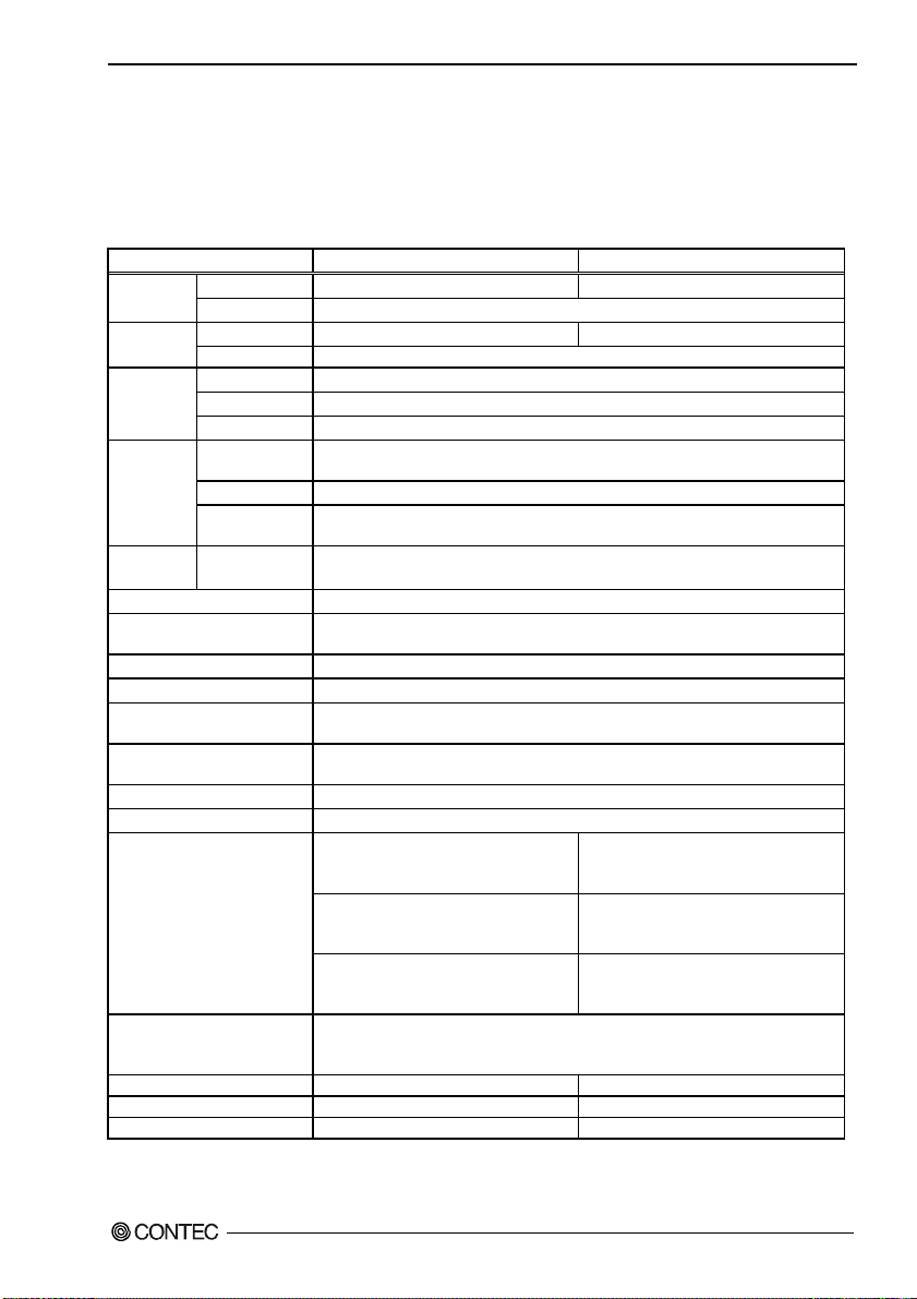
Specifications
Functional Specifications
Table 2.1. Functional Specifications
Type IPC-PT/MV10 series, HPC-HMV10 series IPC-PT/LS10 series, HPC-HLS10 series
LCD type 10.4-inch TFT color LCD (640×480) 12.1-inch TFT color LCD (800×600) LCD type
Number of colors 65536
Resolution 4096×4096 (emulated in 640×480 mode) 4096×4096 (emulated in 800×600 mode) Touch panel
Detection method Analog resistive
CPU
Memory
COM port RS-232C(2ch) COM1(16550, 9-pin D-SUB)
LAN 10BASE-T/100 BASE-TX 1ch, NS DP83816A
PS/2 Keyboard I/F PS/2 type (6-pin MINI-DIN)
PC card slots PCMCIA Type II×2, or TypeIII×1
General-purpose I/O Optocoupler isolated inputs and outputs: 3 channels each
USB 1ch(USB 1.1) <IPC-PT/MV10, IPC-PT/LS10 series>
Output terminals for external
speakers
Front switch & Power LED Front switch input: 3 points; Front Power LED: 3-color display
Video input terminator *3 BNC connector. Input impedance 75Ω
Input power supply
Power supply 100VAC input type: 50VA (Max.)
Outside dimensions (mm) 305(W)×240(H)×51(D) 316(W)×256(H)×54(D)
Panel cut dimensions (mm) 292(W)×227(H) 303(W)×243(H)
Weight About 3.3kg *1 About 3.5kg *1
*1 Does not include cables, optional accessories, and screws, etc.
*2 The number of times of rewriting is 300,000, MTBF=4,797,667hours(CF-CARD)
*3 As for a Video input terminal, only HPC-HMV10 and HPC-HLS10 series are carried.
IPC-PT/MV10 / IPC-PT/LS10 / HPC-HMV10 / HPC-HLS10 Hardware Manual 7
Type SH4 HD6417751RBP 240MHz
Internal cache Data: 16KB, Instruction: 32KB
Clock frequency 240MHz
Flash memory
(NFDISK) *2
System memory 128MB SDRAM
OS loading
Flash memory
32MB
32MB
COM2(16550, 9-pin D-SUB, Settable for RS-422/485)
Capable of using both of keyboard and mouse with commercial PS/2 branch cable
2ch(USB 1.1) <HPC-HMV10, HPC-HLS10 series>
φ3.5 Stereo mini jack Full-scale output level 1.0Vrms(Typ.)
<IPC-PT/MV10AC, HPC-HMV10AC>
100VAC
Input range: 100V~240VAC 50VA
<IPC-PT/MV10DC1, HPC-HMV10DC1>
+12VDC
Input range: 12V±5% 2.5A(Max.)
<IPC-PT/MV10DC2, HPC-HMV10DC2>
+24VDC(insulation)
Input range: 20V~28VDC 2A(Max.)
12VDC input type: 12VDC±5% 2.5A(Max.)
24VDC input type: 24VDC ±20% 2A(Max.)
<IPC-PT/LS10AC, HPC-HLS10AC>
100VAC
Input range: 100V~240VAC 50VA
<IPC-PT/LS10DC1, HPC-HLS10DC1>
+12VDC
Input range: 12V±5% 2.5A(Max.)
<IPC-PT/LS10DC2, HPC-HLS10DC2>
+24VDC(insulation)
Input range: 20V~28VDC 2A(Max.)
Page 13

2. Overview
Installation Environment Requirements
Table 2.2. Installation Environment Requirements
Item Specification
Ambient specifications
Operating temperature 0 to 50ºC
Storage temperature -10 to 60ºC
Humidity 20 to 85%RH(no condensation)
Floating dust particles Not to be excessive
Corrosive gases None
Line-noise
resistance
Vibration
resistance
Impact resistance
Ground Class D grounding (previous class 3 grounding)
Water-proof and dust-proof IP65, front
Line noise AC line: 2kV (IPC-PT/xx10AC series, HPC-Hxx10AC series)
Signal line: 1kV (EN61000-4-4 Level3, IEC1000-4-4 Level 3)
Static
electricity
resistance
Anti-shaking
Contact discharge / 4kV (EN61000-4-2 Level 2, IEC1000-4-2 Level 2)
Atmospheric discharge / 8kV (EN61000-4-2 Level 3, IEC1000-4-2 Level 3)
10 to 50Hz/semi-amplitude 0.15mm
One cycle (10-150-10 Hz) of 1 oct/min test at 19.6 m/s2 (2G) between 57 an
150 Hz x 10 times in three (X/Y/Z) directions (80 minutes each)
(JIS C0040-compliant, IEC68-2-6-compliant)
Tested with 11-ms half-sine wave at 98 m/s2 (10G) three times in each of
tree (X/Y/Z) directions
(JIS C0041-compliant, IEC68-2-27-compliant)
Table 2.3. Power Supply Installation Environmental Conditions for AC Powered Models
(IPC-PT/xx10AC series, HPC-Hxx10ACseries)
Item Specification
Power supply specifications
Allowable instantaneous Less than 17ms (Mean value with ACIN 100 V, Io = 100%)
Power outage
Dielectric strength
2.0kVAC (between input and FG), 10 mA for 1 minute
50MΩ (500VDC)
Power Up Specification for DC Powered Models
+12VDC +24VDC
(IPC-PT/xx10DC1Series, HPC-Hxx10DC1Series) (IPC-PT/xx10DC2Series, HPC-Hxx10DC2Series)
Vol t
11.4V
1~30mS
Vol t
19.2V
18.0V
1~50mS
1~10mS
Time
Time
Figure 2.1. Power Up Specification for DC Powered Models
8 IPC-PT/MV10 / IPC-PT/LS10 / HPC-HMV10 / HPC-HLS10 Hardware Manual
Page 14

2. Overview
Display Optical Specifications
Table 2.4. IPC-PT/MV10 series, HPC-HMV10 series
Parameter Condition Min. Typ.
View angle
(Vertical)
View angle
(Horizontal)
Contrast Display. Monochrome 100 -
Brightness
(at center)
φ = 180° 35deg 45deg
φ = 0° 55deg 70deg
CR⊇5
φ = +90° 60deg 70deg
φ= -90°
Display. White 280cd/m
Display.
Monochrome
60deg 70deg
2
350cd/m
2
Table 2.5. IPC-PT/LS10 series, HPC-HLS10 series
Parameter Condition Min. Typ.
View angle
(Vertical)
View angle
(Horizontal)
Contrast Display. Monochrome 100 -
Brightness
(at center)
φ = 180° 20deg 35deg
φ = 0° 50deg 65deg
CR⊇10
φ = +90° 40deg 60deg
φ= -90°
Display. White
Display.
Monochrome
200cd/m
40deg 60deg
2
250cd/m
2
Contrast ratio (CR) =
Brightness at screen center with white displayed
Brightness at screen center with black displayed
Measurement direction
Z
o
( θ = 0
)
Left
( φ =
-
90o )
X
Bottom
( φ = 0
θ
Top
o
( φ = 180
)
φ
o
)
Y
Module
Right
( φ = 90
o
)
Figure 2.2. Definition of viewable range
CAUTION
The above optical specification data shows optical characteristics of the liquid crystal in the display;
the data does not represent the actual view on the display or its viewing angles.
IPC-PT/MV10 / IPC-PT/LS10 / HPC-HMV10 / HPC-HLS10 Hardware Manual 9
Page 15

2. Overview
Physical Dimensions
IPC-PT/MV10 series, HPC-HMV10 series
51
5
46
226
98.3
48
16
82.5
75
86.774.7
7562
291
4-M4 TAP
(Maximum tapping length:10mm)
50
16 30
106.6
305
107.6
240
[mm]
The illustration above is of the IPC-PT/MV10 series but the check points are the same as with the HPC-HMV10 series.
Figure 2.3. Physical Dimensions < IPC-PT/MV10 series, HPC-HMV10 series >
IPC-PT/LS10 series, HPC-HLS10 series
316
54
5
49
242
75
95.7591.75
249
256
99.3
82.5
48
16
302
70 75
4-M4 TAP
(Maximum tapping length:10mm)
55.5
19 30
[mm]
The illustration above is of the IPC-PT/MV10 series but the check points are the same as with the HPC-HMV10 series.
Figure 2.4. Physical Dimensions < IPC-PT/LS10 series, HPC-HLS10 series >
10 IPC-PT/MV10 / IPC-PT/LS10 / HPC-HMV10 / HPC-HLS10 Hardware Manual
Page 16

3. Each Component Function
3. Each Component Function
Component Locations(IPC-PT/MV10 series, IPC-PT/LS10 series)
Function switch
F1, F2, F3
POWER LED
PCMCIA
I/O
Sound
RESET
USB
LAN
Keyboard
COM1
COM2
Power input
terminal strip
PCI expansion unit
connector cover
* Refer to the software manual for the function switches and POWER LED.
Figure 3.1. Component Locations<IPC-PT/MV10 series, IPC-PT/LS10 series>
Table 3.1. Component Identification<IPC-PT/MV series, IPC-PT/LS10 series>
Component Function
F1, F2, F3 Function Switch
POWER LED Power supply ON display LED
Power input terminal
strip
PCI expansion unit
connector cover
PCMCIA PCMCIA card slot
I/O Isolated I/O connector
Sound Output terminals for external speakers
RESET Hard reset push button
USB USB port connector
UTP Ethernet connector (RJ-45)
Keyboard Keyboard connector (MINI-DIN 6pin)
COM1 Serial port 1
COM2 Serial port 2
Power input terminal strip
Used to attach the PCI expansion unit and to set SW2, SW3,
SW4, and JP5
IPC-PT/MV10 / IPC-PT/LS10 / HPC-HMV10 / HPC-HLS10 Hardware Manual 11
Page 17

3. Each Component Function
Component Locations(HPC-HMV10 series, HPC-HLS10 series)
Function switch
, ,
POWER LED
PCMCIA
I/O
PCMCIA
I/O
Sound
RESET
SPKRST
USB
ACT
UTP USB
LAN
LNK
KB
Keyboard
COM1
COM2
Video
X XX
Power input
terminal strip
PCI expansion unit
connector cover
* Refer to the First Step Guide for the function switches.
Figure 3.2. Component Locations<HPC-HMV10 series, HPC-HLS10 series>
Table 3.2. Component Identification<HPC-HMV10 series, HPC-HLS10 series>
Component Function
, , Function Switch
POWER LED Power supply ON display LED
Power input terminal
Power input terminal strip
strip
PCI expansion unit
connector cover
Used to attach the PCI expansion unit and to set SW2, SW3,
SW4, and JP5
PCMCIA PCMCIA card slot
I/O Isolated I/O connector
Sound Output terminals for external speakers
RESET Hard reset push button
USB USB port connector
UTP Ethernet connector (RJ-45)
Keyboard Keyboard connector (MINI-DIN 6pin)
COM1 Serial port 1
COM2 Serial port 2
Video Video input terminator
VIDEO I N COM2 COM1
12 IPC-PT/MV10 / IPC-PT/LS10 / HPC-HMV10 / HPC-HLS10 Hardware Manual
Page 18
3. Each Component Function
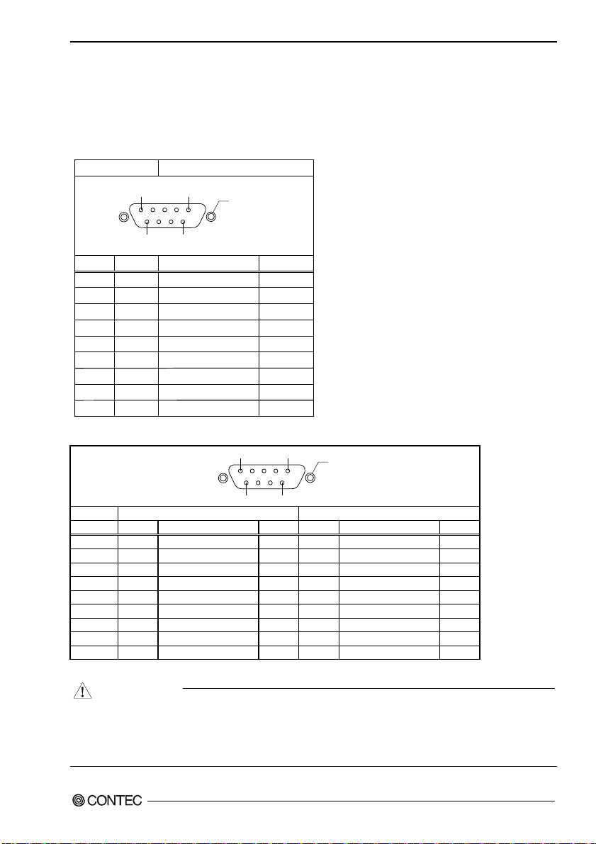
Serial Port Interface (COM1, COM2)
The PANECON-PC is equipped with two RS-232C-compliant serial port connectors (Serial Port 1:
COM1 and Serial Port : COM2).
Table 3.3. COM1 Serial Port Inter Connector
Main unit connector D-SUB 9-pin (Male)
1 5
9
6
Pin no.
Signal
1
2
3
4
5
6
7
8
9
CD
RD
TD
DTR
GND
DSR
RTS
CTS
RI
Carrier detection
Received data
Transm it te d d at a
Data terminal ready
Signal ground
Data set ready
Request to send
Clear to send
Ring indica tor
Table 3.4. COM2 Serial Port Inter Connector
Function
No.4-40UNC
Inch screw
Direction
1 5
In
In
Out
Out
-----
In
Out
In
In
No.4-40UNC
Inch screw
9
6
Pin no. Signal Function Direction Signal. Function Direction
1 CD Carrier detection In GND Signal ground 2 RD Received data In RTS+ Request send + Out
3 TD Transmitted data Out RTS- Request send - Out
4 DTR Data terminal ready Out TXD+ Transmitted data + Out
5 GND Signal ground - TXD- Transmitted data - Out
6 DSR Data set ready In CTS- Clear to send - In
7 RTS Request send Out CTS+ Clear to send + In
8 CTS Clear to send In RXD+ Received data + In
9 R I Ring indicator In RXD- Received data - In
To switch between RS-232C and RS-422/485, set the DIP-SW and JP under the PCI expansion unit connector cover.
CAUTION
RS-232C (Factory setting)
RS-422A/RS485
For TxD, RxD, and RTS, RS-422A/485 pin assignment has even-numbered pins for positive and
odd-numbered ones for negative. For CTS, however, even-numbered and odd-numbered pins are
assigned for negative and positive, respectively, in contrast with other signals. This is not a
description error.
IPC-PT/MV10 / IPC-PT/LS10 / HPC-HMV10 / HPC-HLS10 Hardware Manual 13
Page 19

3. Each Component Function
Switching COM2 between RS-232C and RS-422A/485
To switch between RS-232C and RS-422A/RS-485, change the settings of both of JP5 and SW4’s bit 5.
Setting procedure (JP5)
-RS-232C setting (Factory setting)
1
12
B
C
A
-RS-422A/485 setting
112
B
C
A
Figure 3.3. Setting procedure (JP5)
Table 3.5. Settings for RS-232C and RS-422A/485
RS-232C(Factory setting) RS-422A/485
Setting
procedure
(SW4)
23456
1
7
8
23456
1
78
* When RS-232C is set, SW4’s bits 1 to 4 and 6 to 8 are disabled.
* For SW4’s bits 1 to 4 and 6 to 8 when RS-422A/485 is set, see “COM2 RS-422A/RS-485 data
transmission mode setting” below.
14 IPC-PT/MV10 / IPC-PT/LS10 / HPC-HMV10 / HPC-HLS10 Hardware Manual
Page 20

3. Each Component Function
COM2 RS-422A/RS-485 data transmission mode setting
The data transmission mode setting switch (SW4) can be used to switch between half-duplex and
full-duplex and between RTS and CTS in full-duplex mode. Set the appropriate data transmission
mode depending on the remote device to which to connect this board.
Set the transmission mode using from the bit 6 to bit 8.
Setting procedure
Table 3.6. Data transmission mode setting
Setting
procedure
(SW4)
Description
Half duplex [Half]
ON
23456
1
Only TxD is enabled as a
data line. The
transmission or reception
mode can be selected by
the RTS signal from this
board.
7
8
RTS/CTS self-loop
ON
23456
1
If the connected device has
no RTS and CTS signals, the
CTS signal becomes active by
making the RTS signal of
this board active.
CAUTION
Do not set bits 7 and 8 of each switch to both ON. Doing so may cause the board to malfunction.
Connection Procedure
TX_enable
TXD
RXD
RX_enable
COM2
TXD+ 4
TXD- 5
RXD+ 8
RXD- 9
Figure 3.4. Full-Duplex Connection Method
TX_enable
TXD
RXD
RX_enable
COM2
TXD+ 4
TXD- 5
RXD+ 8
RXD- 9
Figure 3.5. Half-Duplex Connection Method
Full duplex [Full]
7
8
Used with the unit connected
to the RTS and CTS signals
of the connected device
RTS/CTS connection to
remote device
ON
23456
1
7
8
IPC-PT/MV10 / IPC-PT/LS10 / HPC-HMV10 / HPC-HLS10 Hardware Manual 15
Page 21

3. Each Component Function
Terminating resistor setting
When inserting a terminator, use the terminator setting switch (SW4). Set the terminator depending on
the remote device to which to connect the board. The board contains a 100-ohm resistor as a
terminator. See Figure 3.5 for the presence or absence of a terminator for connection to the party line.
Individual bits correspond to different signal lines; bits 1 to 4 serve for CTS, RTS, RxD, and TxD,
respectively.
Setting method
To set the terminal to a resistor other than 100Ω, set the terminator setting switch to OFF and insert an
external terminator.
Table 3.7. Terminator Settings
Setting method
(SW4)
Insert terminator
[Term ON]
ON
23456
1
(A) or (D) below
(either end of signal line)
Ter min ator
(A)
(B)
Figure 3.6. Party Line Connection
(C)
Do not insert terminator
[Term OFF]
ON
23456
7
8
1
(B) or (D) below
(other than end of signal line)
Ter min ato r
(D)
7
8
16 IPC-PT/MV10 / IPC-PT/LS10 / HPC-HMV10 / HPC-HLS10 Hardware Manual
Page 22

3. Each Component Function
Illustrated below are the peripheral circuits for the data transmission mode setting and terminator setting
switches.
8
ST16C550 equivalent
SOUT
SIN
CTS
RTS
DCD
DTR
DSR
RI
Figure 3.7. Setting Switch Peripheral Circuits
Vcc
Vcc
47kΩ
6.2kΩ
6.2kΩ
47kΩ
47kΩ
6.2kΩ
6.2kΩ
47kΩ
SW4
1
Term ina tor
1/2W 100Ω
TxD+
TxD-
RxD+
RxD-
CTS+
CTS-
RTS+
RTS-
IPC-PT/MV10 / IPC-PT/LS10 / HPC-HMV10 / HPC-HLS10 Hardware Manual 17
Page 23

3. Each Component Function
Ethernet (UTP)
Table 3.8. Ethernet connector (RJ-45)
Connector
RJ-45
81
LINK
Pin No.
1
2
3
4
5
6
7
8
Signa
TX+
TX-
RX+
N.C.
N.C.
RX-
N.C.
N.C.
ACT
Remarks
Transmitted data (+) output
Transmitted data (-) output
Received data (+) input
Not connected
Not connected
Received data (-) input
Not connected
Not connected
LED Indicators
- LINK(Green)
Indicates the LINK status.
- ACT(Orange)
Goes on to indicate that data is being transmitted/received.
18 IPC-PT/MV10 / IPC-PT/LS10 / HPC-HMV10 / HPC-HLS10 Hardware Manual
Page 24

3. Each Component Function
Keyboard Interface (KB)
Table 3.9. KB connector
Connector type
MINI-DIN 6-pin
6
5
Pin no.
1
2
3
4
5
6
4
2
Signal
KBD DATA
MOUSE DATA
GND
Vcc (+5V)
KBD CLK
MOUSE CLK
3
1
Remarks
With fuse(max. 1.6A)
Note: A commercially available PS/2 branch cable is required to use a PS/2 mouse.
Product example: KB-PSY02K3 (SANWA SUPPLY)
Note: Use connector 1 for keyboard and connector 2 for mouse.
IPC-PT/MV10 / IPC-PT/LS10 / HPC-HMV10 / HPC-HLS10 Hardware Manual 19
Page 25

3. Each Component Function
PCMCIA (PCMCIA)
PCMCIA compliant card slots are provided [TYPE II×2 (TYPE III×1) size].
Slot 1
Slot 2
Figure 3.8. Slot Numbers and Locations
CAUTION
A type III card should be inserted into slot 2.
Attaching the card removal prevention fitting
PCMCIA Card
Figure 3.9. Attaching the card removal prevention fitting
Power Supply to the Card
The voltage that can be used and the current capacity of each slot are as shown below:
Table 3.10. Power Supply to the Card
Voltage Current capacity (Max.)
+5V 250mA/Slot
+3.3V 250mA/Slot
+12V Not supplied.
20 IPC-PT/MV10 / IPC-PT/LS10 / HPC-HMV10 / HPC-HLS10 Hardware Manual
Page 26

3. Each Component Function
USB port
IPC-PT/MV10 and IPC-PT/LS10 series have equipped one USB interface channel.
HPC-HMV10 and HPC-HLS10 series have equipped two USB interface channels.
Table 3.11. USB connector
14
Pin No. Signal
1 Vcc
2 DATA+
3 DATA4 GND
General-purpose I/O ports (I/O)
The unit has three channels of general-purpose isolated I/O port.
Refer to the software manual for programming this ports.
Table 3.12. General-purpose I/O ports connector
10
Front(LCD) side
Pin No. Signal Remarks
1 PI_PCOM General-purpose input
2 PI(0) General-purpose Input 0
3 PI(1) General-purpose Input 1
4 PI(2) General-purpose Input 2
5 P_PO(0) General-purpose Output 0+
6 N_PO(0) General-purpose Output 07 P_PO(1) General-purpose Output 1+
8 N_PO(1) General-purpose Output 19 P_PO(2) General-purpose Output 2+
10 N_PO(2) General-purpose Output 2Connector: MC1,5/10-GF-3,5(PHOENIX CONTACT)
Cable connector: MC1,5/10-STF-3,5(PHOENIX CONTACT)
↓
1
(plus common)
IPC-PT/MV10 / IPC-PT/LS10 / HPC-HMV10 / HPC-HLS10 Hardware Manual 21
Page 27
3. Each Component Function
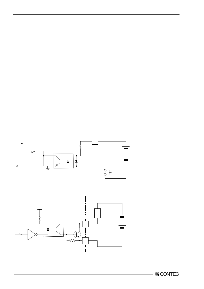
Specifications
[Input section]
- Input specification : Optocoupler-isolated current drive input
- Input resistance : 3kΩ
- Number of input signals : 3
- Input protection circuit : Reverse-connection protection diode provided
- Input response time : Within 100μsec
- External circuit power supply : 12 to 24VDC(±10%)
[Output section]
- Output specification : Optocoupler-isolated open-collector output
- Output rating : 30VDC, 100mA max.
- No. of output signals : 3
- Output response time : Within 300μsec
External Connection
PI_PCOM
10kW
3kW
1/2W
PI(0) to PI(2)
I/O connector
Input
contact
External power supply
(12V to 24VDC)
Figure 3.10. In circuit
(External circuit)
load
External power supply
(Max. 30VDC)
330Ω
PC357
P_PO(0) to P_PO(2)
2SD780A
4.7kΩ
N_PO(0) to N_PO(2)
I/O connector
Figure 3.11. Output circuit
22 IPC-PT/MV10 / IPC-PT/LS10 / HPC-HMV10 / HPC-HLS10 Hardware Manual
Page 28

3. Each Component Function
Power input terminal strip
Power input terminal strip
Screw diameter: M3.5
Terminal strip pitch: 8.9mm
Figure 3.12. Power input terminal strip
IPC-PT/xx10AC series, HPC-Hxx10AC series (100VACIn type)
L
N
Rated input range: 100V to 240VAC
Figure 3.13. Power input terminal strip <100VAC In type>
IPC-PT/xx10DC1 series, HPC-Hxx10DC1 series (+12VDCIn type)
GND +12V
Figure 3.14. Power input terminal strip <+12VDC In type>
IPC-PT/xx10DC2, HPC-Hxx10DC2 series (+24 VDC isolated input type)
GND +24V
Figure 3.15. Power input terminal strip <+24 VDC isolated input type >
CAUTION
All the terminals are identically shaped. Be careful not to connect power at wrong In voltage, or
the unit may cause a fault.
IPC-PT/MV10 / IPC-PT/LS10 / HPC-HMV10 / HPC-HLS10 Hardware Manual 23
Page 29

3. Each Component Function
External Speaker Output Termi n al
Connector: HSJ1456-010330 (HOSIDEN)
Table 3.13. External Speaker Terminal
Pin no.
1
2
3
Signal
GND
Analog signal(R)
Analog signal(L)
Remarks
---
Speaker(Right)
Speaker(Left)
1pin
GND
2pin
R Analog signal
3pin
L Analog signal
Applicable connector: Small jack of φ3.5 mm
Full-scale output level 1.0Vrms(Typ.)
Touch Panel
The PANECON-PC is equipped with an analog touch panel that enables keyboard-less, mouse-less
operations.
Refer to the software manual for details on how to use the touch panel.
Table 3.14. Touch panel specifications
Model IPC-PT/MV10, HPC-HMV10 series IPC-PT/LS10, HPC-HLS10 series
Detection method Analog resistive
Active area 211.2×158.4mm 246×184.5mm
Surface treatment No glare
Resolution 4096×4096 (emulated in 640×480 mode) 4096×4096 (emulated in 800×600 mode)
Operating force 50g±30g
Operating lifetime 1 million touches minimum
(as tested by mechanical touching under 300g of force at a rate of two presses per second)
Setting the SW2 to 4, JP5
SW2
ON
23456
1
7
8
Figure 3.16. SW, JP on main board
Table 3.15. Internal Connectors and SW List
Silk Function Type Remarks
SW2 Setup of boot operation ESD108LT 8pin
SW3 User opening ESD104LT 4pin
SW4 RS-422A/485 mode setting ESD108LT 8pin
JP5 COM2 switching between RS-232C and
RS-422A/485
24 IPC-PT/MV10 / IPC-PT/LS10 / HPC-HMV10 / HPC-HLS10 Hardware Manual
ON
SW3
1
234
ON
1
SW4
23456
7
3pin×12
1
8
JP5
12
B
C
A
Page 30

3. Each Component Function
Setup of OS operation (SW2)
This switch sets OS operation. For details, refer to the software manual.
Default setting
ON
12345678
Default setting of DIP switch
Figure 3.17. Setup of OS operation
CAUTION
Use this setting for normal operation.
DIP switch for applications (SW3)
SW3 is a general-purpose switch available for use by the application. Refer to the software manual for
details on how to use this DIP switch.
Default setting
ON
1234
Default setting of DIP switch
Figure 3.18. General Switch
COM2 RS-422A/485 transfer mode setting DIP-SW (SW4)
See the above description of the serial port interface.
CAUTION
Operating a connector or jumper on the internal CPU board, which is not covered by this manual,
can cause the unit to malfunction or develop operational problems. Never touch any of those
on-board connectors and jumpers.
IPC-PT/MV10 / IPC-PT/LS10 / HPC-HMV10 / HPC-HLS10 Hardware Manual 25
Page 31

3. Each Component Function
Video input terminator
As for a Video input terminal, only HPC-HMV10 and HPC-HLS10 series are carried.
Table 3.16 Video input terminator
Connector
UG-625/U equivalent (HOSIDEN)
1
2
Pin No. Signal
1 GND
2 Input Signal
Applicable connector: UG-88/U equivalent (HOSIDEN)
Input impedance 75
Ω
26 IPC-PT/MV10 / IPC-PT/LS10 / HPC-HMV10 / HPC-HLS10 Hardware Manual
Page 32

4. Hardware Setup
4. Hardware Setup
Installation Requirements
To maintain the ambient temperature within the installation environment requirement range, provide a
gap of 30mm or more between the main unit and any adjacent equipment.
Side view
Panel
30mm or more(above)
30mm or more
(Bottom)
Bottom view
30mm or more(Side)
Interface surface
Panel
30mm or more(back)
Figure 4.1. Distances between the PANECON-PC and Its Vicinity
Card removal prevention fitting
(1) Insert a PC card.
(2) Clip the pawl on the bottom of the fitting into the long slot on the PANECON-PC unit.
(3) Use a screw to attach the top of the fitting.
PCMCIA Card
Figure 4.2. Attaching the card removal prevention fitting
IPC-PT/MV10 / IPC-PT/LS10 / HPC-HMV10 / HPC-HLS10 Hardware Manual 27
Page 33

4. Hardware Setup
Back light exchange
The backlight used in the LCD module has a limited life. When it expires and requires replacement,
contact your local CONTEC sales office.
Attaching the Fitting Used to Attach to the Main Unit
(1) Hold the main unit from the outside of the panel.
Figure 4.3. Attaching the Fitting Used to Attach to the Main Unit < 1 / 2 >
(2) Hold the attachment from the inside of the panel.
Panel
Fitting
Main unit
Tightening the screw excessively
can break the unit.
The appropriate tightening torque
to take drip-proof effect is 0.6 N/m.
Figure 4.3. Attaching the Fitting Used to Attach to the Main Unit < 2 / 2 >
28 IPC-PT/MV10 / IPC-PT/LS10 / HPC-HMV10 / HPC-HLS10 Hardware Manual
Page 34

4. Hardware Setup
Panel cut dimensions Figure
+1
292
-0
R1 or less
+1
-0
227
Panel thickness range 1.6~7mm
[mm]
Figure 4.4. Panel cut dimensions figure <IPC-PT/MV10 series, HPC-HMV10 series>
+1
303
-0
R1 or less
+1
-0
243
Panel thickness r ange 1.6~7mm
[mm]
Figure 4.5. Panel cut dimensions figure <IPC-PT/LS10 series, HPC-HLS10 series>
CAUTION
Use a panel with a thickness in the range 1 to 10mm.
IPC-PT/MV10 / IPC-PT/LS10 / HPC-HMV10 / HPC-HLS10 Hardware Manual 29
Page 35

4. Hardware Setup
Removing the PCI expansion unit connector cover
The PCI expansion unit connector cover on the back must be removed when you install the PCI
expansion unit or set SW2 to SW4 and JP5.
1. Undo the 2 flat-head screws and remove the cover.
Figure 4.6. Removing the PCI expansion unit connector cover
30 IPC-PT/MV10 / IPC-PT/LS10 / HPC-HMV10 / HPC-HLS10 Hardware Manual
Page 36

4. Hardware Setup
Attaching the simple stand
A simple stand is supplied with this product.
1. Use the attached screw (M4 x 8) to fasten the simple stand to the unit.
Figure 4.7. Attaching the simple stand
CAUTION
Using the simple stand involves the risk of letting the unit fall down.
You should therefore use the stand as a simple gadget with meticulous care not to let the unit fall.
IPC-PT/MV10 / IPC-PT/LS10 / HPC-HMV10 / HPC-HLS10 Hardware Manual 31
Page 37

4. Hardware Setup
32 IPC-PT/MV10 / IPC-PT/LS10 / HPC-HMV10 / HPC-HLS10 Hardware Manual
Page 38

5. List of Options
5. List of Options
Screen protective sheets
- IPC-CV : Screen protective sheets for 10.4inch (IPC-PT/MV10 series) (10 sheets)
- IPC-CV12 : Screen protective sheets for 12.1inch (IPC-PT/LS10 series) (10 sheets)
Stand
- IPC-SND-03 : Desk stand
Cable
- IPC-ACCODE3 : AC power cable (2 m, 125 VAC supported)
PCI expansion unit
- IPC-PAC(PCI)-C1 : 1 slot expansion unit for PCI half size
Manual
- IPC-PT/SH4-HMJ : Hardware manual (Japanese) for IPC-PT/MV10, IPC-PT/LS10,
HPC-HMV10, and HPC-HLS10 series
- IPC-SH4CE4-SMJ : Software manual (Japanese) for IPC-PT/MV10 series, IPC-PT/LS10 series
- IPC-SH4CE4-SME : Software manual (English) for IPC-PT/MV10 series, IPC-PT/LS10 series
IPC-PT/MV10 / IPC-PT/LS10 / HPC-HMV10 / HPC-HLS10 Hardware Manual 33
Page 39

IPC-PT/MV10 / IPC-PT/LS10
HPC-HMV10 / HPC-HLS10
Hardware Manual
IPC-PT/SH4-HME
CONTEC CO., LTD. November 2008 Edition
3-9-31, Himesato, Nishiyodogawa-ku, Osaka 555-0025, Japan
Japanese http://www.contec.co.jp/
English http://www.contec.com/
Chinese http://www.contec.com.cn/
No part of this document may be copied or reproduced in any form by any means without prior written
consent of CONTEC CO., LTD. [11062008]
[11062003] Management No. A-46-779
[11062008_rev5] Parts No. LYCX432
 Loading...