

Page 1

PC-HELPER
High Speed & Function IEEE-488.2 I/F Board
for PCI
GP-IB(PCI)F
High Speed IEEE-488.2 I/F Board for PCI
GP-IB(PCI)FL
High Speed & Function IEEE-488.2 I/F Board
for Low Profile PCI
GP-IB(LPCI)F
High Speed IEEE-488.2 I/F Board
for Low Profile PCI
GP-IB(LPCI)FL
User’s Manual
CONTEC CO.,LTD.
Page 2
CD-ROM
[API-PAC(
W32
)]
First ste
p g
uid
e
Board
War
ranty C
ertifi
cate
X
XXXXXXX
XXXXX
XXXX
XXXXXX
XXX
Ser
ial nu
mber la
bel
Warr
anty
Ce
rtifica
te
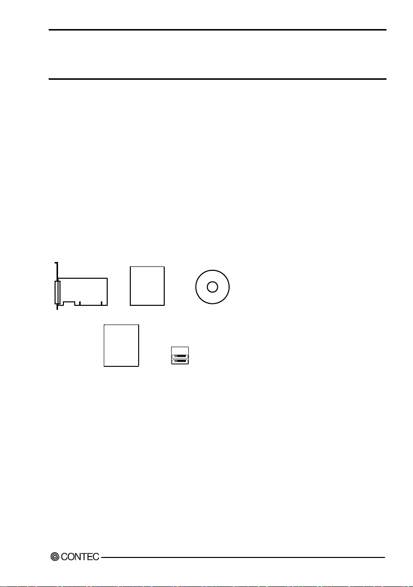
Chec k Your P ac kage
Thank you for pu rc ha s i ng the CO N TEC produ c t.
The product consists of the items lis ted b elow .
Check, with the following list, that your package is co mplete. If you discover damaged or missing items,
contact your retailer.
Product C onfi g uration List < GP-IB(PCI)F, or GP-IB(PCI)FL >
- Board(One of the fol l owing)
[GP -IB(PCI)F, or GP -IB(PCI)FL]
- First step guide … 1
- CD-ROM *1 [API-PAC(W32)] …1
- Warranty Certificate…1
- Serial number lab el…1
*1 The CD-R OM contains the driver software and User’s Guide (this guide)
GP-IB(P CI)F, GP-IB(PCI)F L, GP-IB(LPCI)F i
Page 3
CD
-RO
M
[API-PA
C
(W
32
)
] Sta
nda
rd-
sized
b
r
ac
ke
t
GPIB Connector
Board
Firs
t
st
e
p
g
ui
de
War
rant
y C
ert
ific
ate
XXXXXXXXXXXXX
XX
XXXX
XXX
XXX
X
S
erial number label
Warranty
Ce
rtif
ica
te
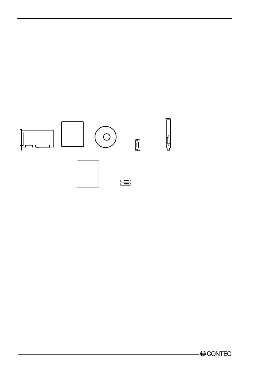
Product Configuration List < GP-IB(LPCI)F, o r GP-IB(LPC I)F L >
- Board(One of the fol l owing)
[GP -IB(LPCI)F, or GP -IB(LPCI)FL]
- First step guide … 1
- CD-ROM *1 [API-PAC(W32)] …1
- GPIB Conne ctor [CN-GP /C] …1
- Standard-sized bracket …1
- Warranty Certificate…1
- Serial number lab el…1
*1 The CD-R OM contains the driver software and Us er’s G u id e (this gu id e)
Copyright
Copyr ight 2013 CONTEC CO., LTD. ALL RIGHTS RESERVED
No par t of this docu m ent may be c opie d or r eprodu ce d i n any f orm b y a ny mea ns withou t prior wri tten
consent of CONTEC CO., LTD.
CONTEC CO., LTD. makes no commitment to update or keep current the information contained in this
d ocu m ent. The inform a ti on i n this docu me nt is s ub j ec t to chang e wi thou t notice.
All rele vant is su es ha ve been c ons i d e red in the prepara t ion of thi s docu me nt. Shou l d you notic e a n
omis s i on or a ny q u e s tionable i tem in thi s d ocument, pl ea s e fe el fr ee to not i fy C O NT EC C O ., L TD .
Reg ardl ess of the foregoing statement, C ONTEC assu mes no responsi b il ity for a ny erro rs that may
appea r i n this d oc u me nt or for res ults ob tai ned b y the u s e r as a result of u s i ng this produ ct.
Trademarks
MS, Micr os oft and Wi nd ows are trad e ma rks of Mi c ros of t C orp orat i on . O th er b ra nd and prod u c t nam es
are trademarks of their respectiv e holder.
ii GP-IB(PCI)F , GP-IB(PCI)FL, GP-IB (L P C I) F, G P-IB(LPCI)FL
Page 4

Table of Contents
Check You r Package .................................................................................................................i
Copyright ................................................................................................................................ii
Trademarks .............................................................................................................................ii
Table of Contents ...................................................................................................................iii
1. BEFORE USING THE PRODUCT 1
Ab out the Boar d ......................................................................................................................1
Features ............................................................................................................................1
Support Soft ware...............................................................................................................2
Cable & Connector (Optio n) .............................................................................................3
Customer Support ....................................................................................................................4
Web Sit e ...........................................................................................................................4
Limited T hree-Y ears Warran ty .................................................................................................4
How to Obtain Service .............................................................................................................4
Liability ..................................................................................................................................4
S afety Precauti ons ...................................................................................................................5
Safe t y Informat ion.............................................................................................................5
Handling Precaution s.........................................................................................................6
Environment .....................................................................................................................7
Inspection .........................................................................................................................7
St orage .............................................................................................................................7
Disposal............................................................................................................................7
2. SETUP 9
What is Setup ?.........................................................................................................................9
Using the B oard un der Windows U s i ng t he D river Library API-PAC(W32) ..........................9
Us i ng the B oa rd u nder Wind ows Us i ng Softw are Other than the Driver Library
API-PAC(W32).................................................................................................................9
Using the Board under an OS Other than Windows............................................................10
S tep 1 Install i ng th e Software .................................................................................................11
About the dri ver to be use d ..............................................................................................11
Starting the Install Program..............................................................................................12
For using API-GPIB(98/PC)xx .........................................................................................13
For using API-GPLV(W32) .............................................................................................15
Step 2 Settin g the Hardware ...................................................................................................16
Parts of the Board and Factory Defaults ............................................................................16
Setting the Board ID ........................................................................................................17
Plugging the Bo ar d ..........................................................................................................17
Using the Connector Adaptor (for the GP-IB(LPCI)F, GP-IB(LPCI)FL) ............................18
GP-IB(P CI)F, GP-IB(PCI)F L, GP-I B(LPC I)F , GP -IB(LPCI)FL iii
Page 5

S tep 3 Installing the Hardw are ................................................................................................19
Tur ni ng on t he PC ...........................................................................................................19
Sett in g with the Found New Hardware Wizard ..................................................................19
S tep 4 Initializing the Software...............................................................................................21
For using API-GPIB(98/PC)xx .........................................................................................23
For using API-GPLV(W32) .............................................................................................24
Step 5 Checking Operat ions with the Diagnosis Program..........................................................25
What is the Diagnosis Program? .......................................................................................25
Che ck M ethod.................................................................................................................25
Setup T roubleshoot ing ...........................................................................................................28
Symptoms and Actions ....................................................................................................28
If your pro blem ca nnot be resolved...................................................................................28
3. EXTERNAL CONNECTION 29
How to connect the connectors ...............................................................................................29
Connect or shape ..............................................................................................................29
Connect or Pin Assignment ...............................................................................................29
Notes on c able connection................................................................................................30
4. FUNCTIONS 33
Bus M ast er Fun ction ..............................................................................................................33
Bus Master Transfer ........................................................................................................33
Basic GPIB Functions ............................................................................................................34
Master/slave function ......................................................................................................34
Communicat ion function..................................................................................................34
Ser ia l poll/par alle l poll/SRQ send functions ......................................................................34
My address setting...........................................................................................................34
Additional Functions..............................................................................................................35
Line mo nitor functio n ......................................................................................................35
Com municati on us ing FIFO m emory ................................................................................35
Analyzer funct ion ( GP-IB(PCI)F, GP-IB(LPCI)F) .............................................................35
5. ABOUT SOFTWARE 39
CD-ROM Directory Structure .................................................................................................39
About Software for Windows .................................................................................................40
For using API-GPIB(98/PC)xx ...............................................................................................40
Accessin g the Help File ...................................................................................................40
Using Sample Programs...................................................................................................41
For using API-GPLV(W32)....................................................................................................43
Accessin g the Help File ...................................................................................................43
Function List...................................................................................................................44
Using Sample Programs...................................................................................................47
iv GP-IB(PCI)F , GP-IB(PCI)FL, GP-IB (L P C I) F , G P-IB(LPCI)FL
Page 6

Uninstalling the API Func ti on L ibraries ............................................................................48
About Software for L inux.......................................................................................................49
Driver Software Install P rocedure.....................................................................................49
Accessin g the Help File ...................................................................................................50
Using Sample Programs...................................................................................................50
Unins talling the driver .....................................................................................................50
6. ABOUT HARDWARE 51
Hardware specification...........................................................................................................51
Res t ri ction s and Notes ...........................................................................................................54
How to Rep lace t h e GP-IB(LPCI)F, GP-IB(LP CI)FL Bracket ............................................54
Posit ioning the GPIB Adaptor for the GP-IB( LPCI)F, GP-IB(LPCI)FL..............................55
GP-IB(P CI)F, GP -I B(PC I)FL, GP-IB(LP CI)F, GP-IB(LPCI)FL v
Page 7

vi GP-IB(PCI)F , GP-IB(PCI)FL, GP-IB (L P C I) F , G P-IB(LPCI)FL
Page 8

1. Before Using t he Product
This not only allows the signals on the GPIB bus t o analyzed, but also permits signal analysis to be
1. B ef ore U sing t he Product
Abo ut the B o ard
This product is a P CI bus compatible i nterface b oard wi th support for b u s ma s ter ope rat i on a nd which
complies w ith IEEE-488.1 and IEEE-488.2. The card can be u sed in a PC to control communica tions
w ith devices that support the G PIB interface and perform G PIB bu s line data analysis .
You can u s e the s u ppl i ed driver l ibrary to deve l op appl i ca tion software u s i ng a ny prog r amming
language that supports t he Win32 API routines (such as Visual Basic or Visual C++), or using
LabVIE W.
Features
Complies w it h t he IEEE-488.2 standard
- As the card com plies with the IEEE-488.2 standard, you can control any external device that supports this
standard.
Data transfer speed 1.5Mbyte/sec max.
- The maximum data transfer speed for commu nicatio ns is 1.5Mbyte/sec.
Supports bus master operation
- The bus master data transfer function enabl es larg e q u antities of data to be transferred b etw een the
b oard and PC without loading the CPU.
Internal 2Kby te FIF O buffers for send and rec eive
- The board has sepa ra te 2Kbyte FIF O b uffers for sending and recei ving d ata, allow i ng b oth small a nd
large volumes of data to be transferred at high speed.
- Interfa ce m ess ag e s also u se a F IFO to en abl e hig h-speed transmission.
Built-in G PI B bus analyzer function
- The board features a bu s analyzer function. [GP-IB(PC I) F , GP-IB(LPCI)F]
perform ed while the b oa rd i s performing GPIB c ommu ni ca t ions
Built-in SPAS ev en t func tio n
- In ad dition to the fu nc tion s of the ea rl i er GPIB contr ol le r (µPD 7210), th e board a l s o s u pports the
S PA S event g ene rated w he n a s e ri al pol l occ u rs . This gives you a hig h l eve l of fl exi b i l ity i n
cons tru cting your s ys tem .
In ternal high-precision timer
- The board includes a high-precision applicatio n timer to al low accu rate time monitoring to be
performed under Windows.
Long t erm av aila b ilit y
- As the boar d us es a high-s pee d GPIB controller develo ped by CO NTE C (upwardl y compatibl e wit h
the µPD7210 ), re li able long term availability is ensured.
Diagnostic program
- A diagnostic program is supplied to support system development. The diagnostic program can be used to
check hardware operation (interrupts and I/O addresses) and to perform simple communication tests with
connected devices.
GP-IB(P CI)F, GP -I B(PC I)FL, GP-IB(LP CI)F, GP-IB(LPCI)FL 1
Page 9

1. Befor e Usin g the Product
O ther
- A function is provided to read all control lines and data lines. This enables various operations to be
p er forme d from the a ppl ication. [Inc ludes control line latch f uncti on. Data lines are only support ed
on the G P-IB(PCI)F and GP-IB(LPCI)F.]
- S upport for b oth of Low Profil e s iz e and s tandard s i ze s l ots (i nterc hangeabl e with a bu ndled
bracket). [GP -IB(LPCI)F, GP -IB(LPCI)FL]
Support Software
You shou l d us e CON TEC s upport software ac cording to you r pu rpos e and developm e nt environment .
NOTE:
This hardware does not support Windows 95 and Windows NT4.0/3.51.
Driver Library API-PAC(W32) (Bundled)
API-PAC(W 32) is the l i b ra ry s oftw a re tha t prov i d e s the commands for CON TEC ha rd ware produ ct s in
the form of Windows s tandard Win32 A PI fu nc ti on s ( DL L). I t makes i t eas y to cre at e high-speed
appl i cation s oft ware taking a dvantage of th e CO NT EC har dwa re us ing vario us programmi ng language s
that s upport Win3 2 A P I fu nc tio ns , s u c h as Visual Bas i c and Vi s u a l C+ + .
It can also be used by the installed d iag nosis program to check hardw are operations.
CO N TEC provide s download services (at http://www.contec.com/apipac/) to s upply the updated dri ver s
and differential files.
For details, read Help on the bund led CD-RO M o r visit the CONTEC’s Web site.
< Operating environment >
OS Windows 7, Vista, XP, Server 2008, 2003, 2000
Adapta tion language Visual C++ .NET, Visual C# .NET, Visual Basic .NET, V i sual C++, Visual Basic,
API-GPLV(W32) li b r ary s upporting LabVIEW (Supplied: Stored on the API-PAC(W32) CD-ROM)
API-GP LV(W32) is a driver created according to the National Instruments Corporat ion’s GPIB fun ction
style. The driver is software to control the CONTEC GPIB board (PC Cards ) us ing a LabV IEW-based
G PIB sys tem or exi s ting applic at i on program.
De lphi, C++Buil de r, etc..
It can also be used by the installed d iag nosis program to check hardw are operations.
CO N TEC provi d e s d ownload s e rvi ce s (at http://www.contec.com/gplv/) to s u ppl y the updated drivers
and differential files.
For details, read Help on the bund led CD-ROM or visit the CONTEC’s Web site.
< Operating environment >
OS Windows 7, Vista, XP, Server 2008, 2003, 2000
Adapta tion language LabVIEW, V isual C++ .NET, Visual C# .NET, Visual Basic .NET, Vi sua l C++,
Visual Basic, Delphi , C++Bui lder, etc..
2 GP-IB(PCI)F , GP-IB(PCI)FL, GP-IB (L P C I) F , G P-IB(LPCI)FL
Page 10

1. Before Using t he Product
Linux versi on of g e nera l -pu rpos e c ou nt d ri ve r: API-GPIB(LNX)
(Suppli e d : Store d on the API-PAC(W32) CD-ROM)
This d r ive r i s us ed to control C O NTE C GPIB b oar d s (PC C ar d s ) from w i thin Li nu x.
You c an c ont rol C ONTEC GPI B boar ds ea s ily usin g the sh ared libra ry c alled from the user appli cation,
the d evi ce d ri ve r (mod ule) for e ac h kerne l vers i on, a nd the b oard (PC C ards) confi g uration pr o g ra m
(config).
CO N TEC provide s download services (at http://www.contec.com/apipac/) to s uppl y the updated drive rs
and differential files.
For details, read Help on the bund led CD-ROM or visit the CONTEC’s Web site.
< Operating environment >
OS RedHatLinux, TurboLinux, etc..
(F or details on supported distributions, re fer to He lp available after installation.)
Adaptation languag gcc, etc..
Ca ble & Co nnect o r (Option)
GPI B cable (2m) : PCN-T02
GPI B cable (4m) : PCN-T04
GPIB Connector : CN-GP /C
Effective when the cable b eing plu g ged into the board interfere
wit h the PC’s main unit . See the troubleshooting section at t he end
* Check the CONTEC’s Web s i te for more i nfo rmation on the s e opt i on s .
of C hapter 2. (Included with GP-IB(LPCI)F and GP-IB(LPCI)FL)
GP-IB(P CI)F, GP -I B(PC I)FL, GP-IB(LP CI)F, GP-IB(LPCI)FL 3
Page 11

1. Befor e Usin g the Product
Customer Support
CO N TEC provide s t he following s upport se rvi c e s for you to use C ON TE C pr odu cts mo re ef fi ci ently a nd
comfortably.
We b Sit e
Japanese http://www.contec.co.jp/
English http://www.contec.com/
Chinese http://www.contec.com.cn/
Latest produ ct informatio n
CO N TEC provi d e s u p-to-d a te i nfor ma t ion on prod u c ts.
CO N TEC al s o provi des prod uct manua ls a nd va ri ou s tec hnic al d oc u me nts in the PDF .
Free dow nload
You can download updated driver so ftware and differential files as well as sample programs available in
several langu ag es.
Note! For prod uct information
Contact your retailer if you have any technic al q ues tion abou t a CONTEC product or need its price,
delivery time, or estimate information.
Limited Three-Years Warranty
CONT EC products are w arranted by CO NTEC C O., LTD. to be free from defects in material and
work mans hi p for u p to thre e ye ar s from th e d ate of pu rc has e b y the ori g i nal purcha s er.
Repair wil l be fr ee of cha rge only wh en this dev ice is returned freight pre paid with a copy of the or i ginal
invoice and a R eturn Merchandise Au thorization to the di stribu tor or the C ONTE C group offic e, fro m
wh ich it was purchased.
This w arranty is not applicabl e for scratches or normal w ear, bu t only for the electronic circu itry and
original boards . The warran ty is no t applicable i f the device has bee n ta mpered w ith or damag ed through
abu s e, mistreatment, neglec t, or unreas onable u s e, or if the original in voice is n o t included , in w hich case
repa irs w i l l be consi d e re d b e yond the warranty poli cy.
How to Obtain Ser vice
For replacement or repair, retu rn the d evice freight prepa id, wi th a c opy of the or i g i na l i nvoi ce . Ple as e
obt ain a Ret urn Merchandise Authorizat ion Number (RMA) from the CONTEC group office where you
pu rcha s ed befor e re tur ning any product.
* No product wil l be acce pted b y C O N TEC g r ou p without the RM A numb er.
Liability
The obligation of the warrant or is solely to repair or replace the product. In no event will t he warrantor
be liable for any incident al or consequential damages due to such defect o r consequences t hat arise from
inexperienced u sag e, misu se, or malfunction of thi s d evice.
4 GP-IB(PCI)F , GP-IB(PCI)FL, GP-IB (L P C I) F , G P-IB(LPCI)FL
Page 12

1. Before Using t he Product
DAN
GER
DAN GER ind ic ates a n i mmine ntly ha za r dou s s i tua tion which, i f not avoi d e d , will
W
ARNING
CAUTION
Safe ty Pre cautions
Und e rs tand the fol l owing definiti ons and precautions to use the product safely.
Safety Informat ion
This document provides sa fe ty i nformation us ing the fol lowi ng s ymbols to p re v e n t acc idents res ulting i n
injury or death and the des t ructi on of equipment an d resources. Understand the meanings of t hese labels
to operate the equ ipment safely.
res u l t in de ath or s er ious inj u ry.
WAR NING ind icates a potentially hazardo u s s ituation w hich, if not avoid ed , could
res u l t in de ath or s er ious inj u ry.
CAUTION indicates a potentially hazardous situation w hich, if not avoided , may
result in minor or moderate injury or i n property d ama g e .
GP-IB(P CI)F, GP -I B(PC I)FL, GP-IB(LP CI)F, GP-IB(LPCI)FL 5
Page 13

1. Befor e Usin g the Product
DA
NGER
C
AUT
ION
Handling Precautions
Do not use the product where it is exposed to flammable or corrosive gas. Doing so may result in an
explosion, fire, electric shock, or failu re.
- There are sw i tches on the board that need to be set in advance. Be su re to check these before
installing the board.
- Onl y s et the s w i tche s and j umpers on the b oa rd to the spec i fie d s e tting s .
Otherwi se, the board may malfunction, overheat, or caus e a failu re.
- Do not stri ke or bend the b oa rd . Doing so could damage the board.
Otherwis e, the board may malfunction, overheat, cau se a fail ure or breakage.
- Do not touc h the b oard's me tal pl at e d terminals (e d ge conne ct or) wi th you r ha nd s .
Otherwi se, the board may malfunction, overheat, or caus e a failu re.
If the terminals are touched b y s omeone's ha nd s , c l ea n the term i nals with ind u s tria l al cohol .
- Whe n y ou us e the b oa rd i n a noisy environment or a re nervou s a b ou t nois e , attach f e rrite co res t o t he
connection cab le.
- Do not ins t al l or re m o ve the b oa rd to or from t he s l ot while th e co mputer's power is turned on.
Otherwi se, the board may malfunction, overheat, or caus e a failu re.
Doi ng s o c ou l d ca u s e trou b l e. B e s ure that the perso nal c om pu t e r or t he I/O e xp ansion unit power is
turned off.
- Make s u re that your PC or e xpa n s i on u ni t can supply ample power to al l the b oar d s i ns tall e d .
Insufficiently energized b oards could malfunction, overheat , or cause a failu re.
- The specifications o f this pro duct are subject to chan ge without notice for enhancement and quality
improvement.
Even when usin g the product c ont inuo us ly, be sure t o re ad the man ual and underst and the c ont ents.
- Do not mod if y the product. CO NT EC will b e ar no r es pons i b i l ity for a ny prob l e ms , e tc ., r es u l ting
from mod i fyi ng this product.
- Reg ardl ess of the foregoing statements, CONTEC i s not liab le for any damag es whatsoever
(inc l u d i ng da mages for los s of bu s i nes s profi ts ) ar is i ng out of the use or i nability to u s e this
CO N TEC prod uct or the i nfor mation con t a ine d he rei n .
- Points to note when inst alling the GP-IB(LPCI)F board and t he GP -IB(LPCI)FL board are listed in
"Chapter 6 Res trictions and Notes". Please read these beforehand.
6 GP-IB(PCI)F , GP-IB(PCI)FL, GP-IB (L P C I) F , G P-IB(LPCI)FL
Page 14
1. Before Using t he Product
* Check that the bus connector
Environment
Us e this product in the fol l owing e nvi ron me n t . If u s ed i n a n u na u thoriz ed environm e nt, the b oa rd may
overheat, malfu nction, or cause a failure.
Operating temperatu re
0 - 50°C
Humidity
10 - 90%RH (No condensation)
Corrosive gases
None
Floating du st particles
Not to be excessive
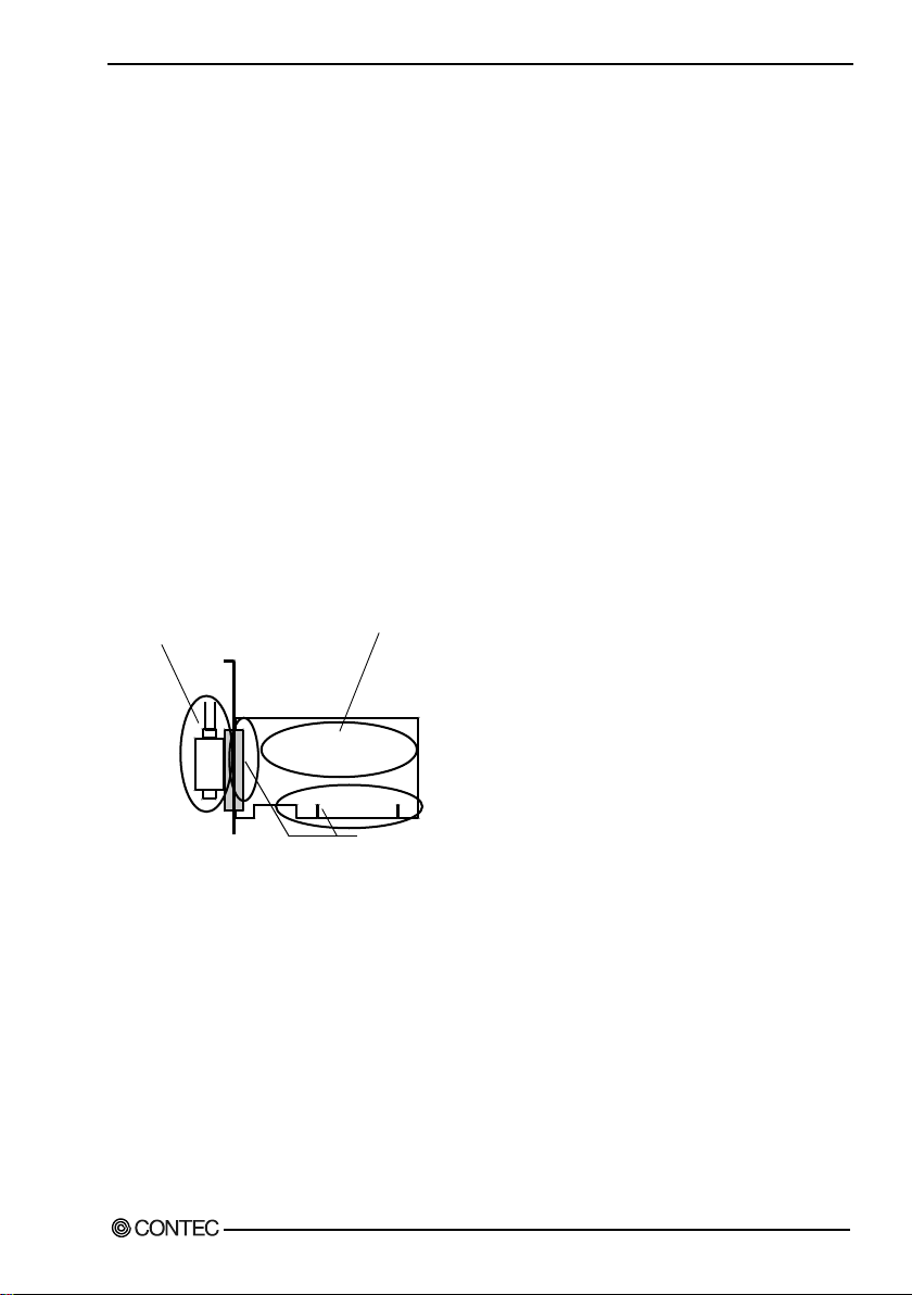
Inspection
Inspect the prod u ct periodicall y as follows to us e it safely.
of the board and its cable have
been plugged correctly.
Storage
When s toring thi s prod u c t , kee p i t in i ts ori g i na l pa cki n g form.
(1) Put the board in the storage bag.
(2) Wrap i t in the pac ki ng material, the n pu t i t in the b ox.
(3) Store the package at room temp eratu re at a place free from d irect sunlig ht, moisture, shock,
vib r ation, mag ne tis m, and s tatic electricity.
Disposal
When d i s pos i ng of the produ ct, fol l ow the d is posal proce d ures s tipulated u nd e r the re le vant laws and
municipal ordinances.
GP-IB(P CI)F, GP -I B(PC I)FL, GP-IB(LP CI)F, GP-IB(LPCI)FL 7
* Check that the board has
no dust or foreign matter adhering.
*
*
* The gold-plated leads of the bus connector
have no stain or corrosion.
Page 15

1. Befor e Usin g the Product
8 GP-IB(PCI)F , GP-IB(PCI)FL, GP-IB (L P C I) F , G P-IB(LPCI)FL
Page 16

2. Set up
Taking the following steps sets up the software and hardware. You can use t he diagnosis program later
2. Setup
This chapter expla ins how to set u p the b oar d .
What is Se tup?
S etup means a series of steps to take before the produ ct can be used .
Different steps are requ ired for softw are and hardw are
The setup procedure varies w i th the OS and applications u sed .
Using the Board unde r Windows
Using the D riv e r Libra ry API -PAC(W32)
This section des crib es the setup procedure to be performed b efore you can start developing applicatio n
programs for the board using the bundled CD-ROM “Driver Packag e API-PAC(W32)”.
to check w hether the software and hardw are fu nction normally.
Step 1 Install in g the Soft war e
Step 2 Setting the Hardware
Step 3 Installing the Hardware
Step 4 Initia lizi ng the S oft war e
Step 5 Checking Operations with the Diagnosis Program
If S e tup fails to be performed normally , see the “S etu p Troub l es hoot i ng ” sectio n at the end of this
chapter.
Using the Board unde r Windows
Using Software Othe r than the D riv e r Libra ry
API-PAC(W32)
For s e tting u p s oftware other tha n API -P AC (W 3 2), refe r to the man u al for that software. See al so the
foll owing parts of this ma nu al a s required.
This c hapter Step 2 Setting the Hardware
This c hapter Step 3 I nstal l i n g th e Har dware
Chapter 3 E xternal C onn e ction
Chapter 6 About Hardware
GP-IB(P CI)F, GP -I B(PC I)FL, GP-IB(LP CI)F, GP-IB(LPCI)FL 9
Page 17

2. Setup
Using the Board unde r an OS Othe r than Windows
For using the boa rd under a n OS other than Wi nd ows, s ee the fol lowing par ts of this ma nu a l .
This c hapter Step 2 Setting the Hardware
Chapter 3 E xternal C onn e ction
Chapter 6 About Hardware
10 GP-IB(PCI)F , GP-IB(PCI)FL, GP-IB (L P C I) F , G P-IB(LPCI)FL
Page 18

2. Set up
Corporat ion (hereaft er NI), allowing the GPIB488, GP IB488.2, and VISA functions of LabVIEW to be
driver t o be us ed
Purpose
- Used t o use CONT EC functions
Ste p 1 Installing the So ftwa re
This e xpla i ns how to i nstall the driver library.
Before installing the hardware on the PC, install the driver libra ry from the API-PAC(W32)
CD-ROM provided with the board.
The following d e s cr iption a s s u me s the oper at i n g s ys tem a s Windows X P. Although some u s e r
interfaces are different depending on the OS u sed , the basic procedure is the same.
Abo ut the driv er t o be use d
Two GPIB communication drive rs c om e w i th you r board : A PI-G PIB(9 8/P C ) and
API-GP LV(W3 2).
API-GPIB(98/PC) provides a C ONTEC proprietary function i nterface.
API-GPLV(W32) provides a function interface eq u ivalent to that from National Instru ments
us ed directly and application prog rams created for NI boards to run without modification.
Select ion guide
G iven below is a guid eline for easily selecting the appropriate d river for the board.
API-GPIB(98/PC)
API-GPLV(W32)
GP-IB(P CI)F, GP -I B(PC I)FL, GP-IB(LP CI)F, GP-IB(LPCI)FL 11
- To make the board operate as fast as possib le
- To convert (d i gi tize) binary and s tring d ata easily
- To us e exis ting a ppli c ations f or NI b oa rd s
- To use LabVIEW
- F ami l ia r w i th NI fu nc tions b ut not wi th CO N TEC functio ns
Page 19
2. Setup
CAUTION
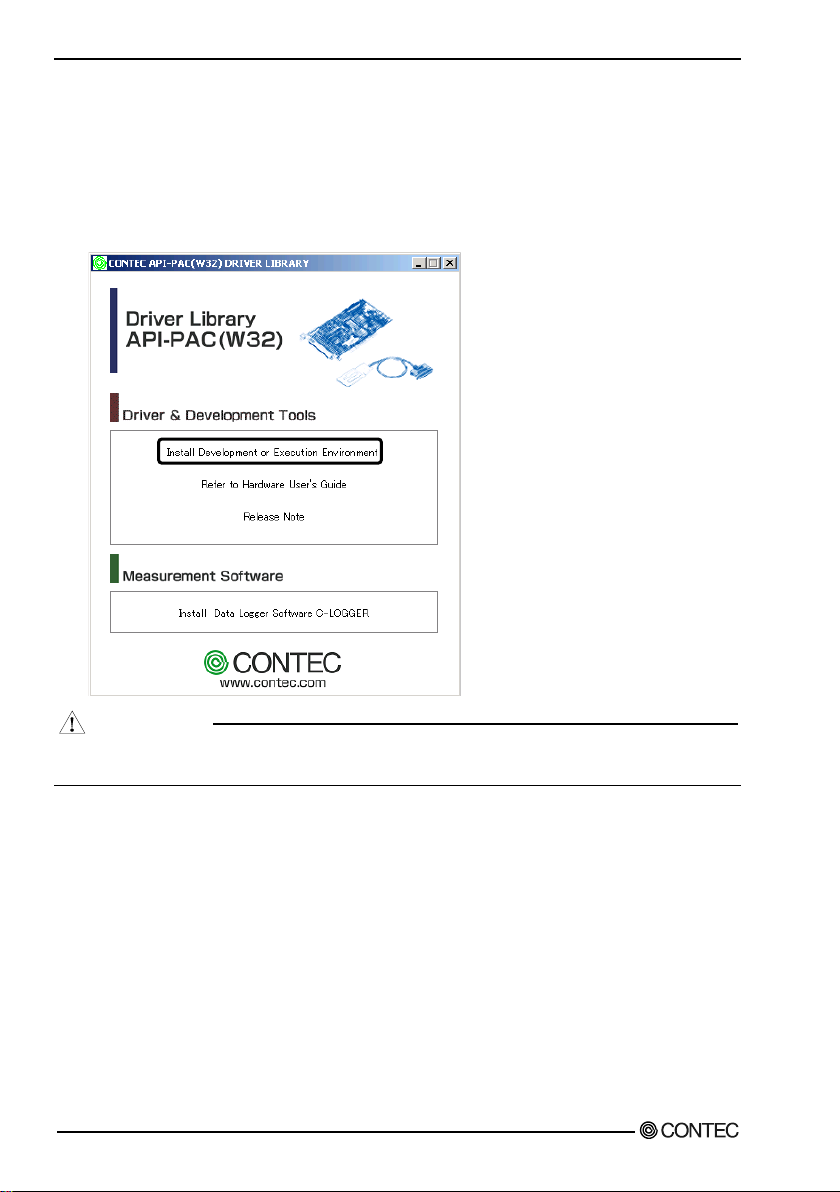
Starting the Install Program
(1) L oad t he CD-ROM [API-PAC(W32)] on yo u r PC.
(2) Th e API-PAC(W 32 ) I ns ta lle r window ap p e a rs aut om aticall y .
If the panel d oe s not appea r, run (CD-ROM drive letter):\AUTORUN.exe.
(3) Click on the [Install Development or E xecution E nvironment] button.
Befor e i ns tal li ng the s of tw ar e i n Windows X P, Server 2003, 2000, or NT, l og i n as a us er w i th
administrator privileges.
12 GP-IB(PCI)F , GP-IB(PCI)FL, GP-IB (L P C I) F , G P-IB(LPCI)FL
Page 20

2. Set up
For us ing API-GPIB(98/PC)xx
Select API- GPIB(98/PC)
(1) The followin g d ialog box app ea r s to sel e ct “Driv er Type” and “Install Type”.
(2) Select “GPIB Communication”.
(3) Select “Driver, Help, etc..(Full Install)”.
(4) Click on the [Install] button.
GP-IB(P CI)F, GP -I B(PC I)FL, GP-IB(LP CI)F, GP-IB(LPCI)FL 13
Page 21

2. Setup
Executing the Installation
(1) Fol l ow the on-screen instructions to proceed to install.
(2) When the requi red files have been copied, the “Perform a hardw are setup now” and “Show readme
file” check boxes are displayed.
When you are install ing the software or hardw are for the first time:
1) Uncheck “Perfo rm a hardwa re setup now”.
2) Click on the [Finish] button. Go to Step 2 to set and plug the hardware.
* When the hardw are has alread y been installed:
Check “Perform a hardw are setup now”, then g o to Step 4 “Initializing the Software”.
You h ave now finished i nstalling the software.
14 GP-IB(PCI)F , GP-IB(PCI)FL, GP-IB (L P C I) F , G P-IB(LPCI)FL
Page 22

2. Set up
For us ing API-GPLV(W32)
Select API-GPLV( W32)
(1) The followin g d ialog box app ea r s to sel e ct “Driver Type ” and “Install Type”.
(2) Select “GPIB for LabVIEW API-GPLV(W32)”.
(3) Select “Driver, Help, etc..(Full Install)”.
(4) Click on the [Install] button.
Executing the Installation
(1) F ollow the on-s creen instruct ions to proceed to instal l.
(2) Th e driver installation is completed when the GPIB setup uti lity is started.
If you are installing the software and hardware for the first time, click on the [Cancel] button in th is
step to terminate the installation procedure.
* When the hardw are has already b een installed:
Go to “For Using API-GPL V(W32 )” in Step 4 "Initializing the S oftware".
GP-IB(P CI)F, GP -I B(PC I)FL, GP-IB(LP CI)F, GP-IB(LPCI)FL 15
Page 23

2. Setup
GP-IB(PCI
)x
SW1
BOARD ID
SW1
BOARD ID
0
1
2
3
4
5
6
7
9
A
B
C
D
E
F
8
- Interface connector
(
CN1
)
- Board ID setting switch
(SW1)
GP-IB(LPCI)x
SW1
BOARD ID
SW1
BOARD ID
0
1
2
3
4
5
6
7
9
A
B
C
D
E
F
8
- Interface connector
(CN1)
- Board ID setting switch
(SW1)
S te p 2 S e tting the Ha rdware
This section des crib es how to set the b oa rd a nd pl u g it on you r PC.
The board has some sw i tches and jumper to be preset.
Che ck the on-board switche s and jumpe rs before pl u g ging the boa rd i nto an e xpans i on s l ot.
The board can be set up even wit h th e factory def aults untouched. Yo u ca n chan ge board sett ings later.
Parts of the Board and Factory Defaults
Figure 2.1. to. s how the names of maj or pa rt s on the b oa rd .
Note that the sw itch setting s hown b elow is the factory defaul t.
GP-IB(PCI)F , GP-IB(PCI)FL
Figu re 2.1. Part Names(GP-IB(PCI)F, GP-IB(PCI)FL)
GP-IB(LPCI)F , GP-IB(LPCI)FL
Figu re 2.2. Part Names(GP-IB(LPCI)F, GP-IB(LPCI)FL)
16 GP-IB(PCI)F , GP-IB(PCI)FL, GP-IB (L P C I) F , G P-IB(LPCI)FL
Page 24

2. Set up
To set the board ID, use the rotary switch on the board. T urn the SW1 knob to set the board ID as shown
BOAR
D ID
SW1
0
1
2
3
4
5
6
7
9
A
B
C
D
E
F
8
(B
oar
d I
D =
0)
Factory s
ett
ing
:
Se tting the B oard ID
If you i ns tall two or more boards on one pers ona l comp uter , a s s i g n a d i ffe rent ID val u e to eac h of the
boards to distinguish them.
The board IDs can be set from 0 - Fh to identify up to si xteen boards .
If only one b oa rd i s us e d , the orig i nal fa ctory setting (Board ID = 0) should be used.
Setting Procedure
below.
Figu re 2.3. Board I D Settin gs (S W 1)
Plugging the Board
(1) Before plugging the board , s hut down the sys tem, u npl ug the power c od e of you r PC .
(2) Remove the cover from the PC so that the board can be mounted.
(3) Plu g the boa rd i nto an expa ns i on s l ot.
(4) Fasten the board bracket to the PC’s chassis w ith the removed screw .
(5) Pu t th e c over back into place.
(T he photograph shows the card installed in a PCI slot.)
GP-IB(P CI)F, GP -I B(PC I)FL, GP-IB(LP CI)F, GP-IB(LPCI)FL 17
Page 25

2. Setup
AB
5V key
3.3V key
<PCI bus slot> <PCI bus board>
5-V PCI bus slot
3.3-V PCI bus slot
A :
B :
Slit for 5-V PCI bus slot
Slit for 3.3-V PCI bus slot
CN-GP/C
GPIB
Cable
GPIB
Cable
Board Board
CAUTION
Applicable PCI bus slots
PCI b us s l ots use d in PCs ha ve ke ys to preve nt 5V and 3.3V PCI b u s boa rd s from b ei ng a cc i d e ntall y
plugged into wrong bus slot s. T his board can be plu g g e d into both of th e 5V and 3.3V PCI b u s sl ots.
Using t he Co nne c t o r Ada pt o r (f o r the GP-IB(LPCI)F, GP-IB(LPCI)FL)
When connecting the GPIB cable to the GP -IB(LPCI)F, GP -IB(LPC I)FL, the cable may be ob structed
by the PC case. T o avoid this, fit the su pplied CN-GP/C c onnec to r adapto r a s s hown b el ow.
- Do not touc h the b oard's me tal pl at e d terminals (e d ge conne ct or) wi th you r ha nd s .
Otherwi se, the board may malfunction, overheat, or caus e a failu re.
If the termi nal s ar e tou che d b y someone's ha nd s , c lean the terminals w ith industrial alcohol.
- Do not ins t al l or re m o ve the b oa rd to or from t he s l ot while th e co mpute r' s po wer is tu rned on.
Otherwi se, the board may malfunction, overheat, or caus e a failu re.
Doing so could cau se trouble. B e su re that the pe rs o nal com pute r or t he I/O e xp ansion unit power is
turned off.
- Make s u re that your PC or e xpa n s i on u ni t can s upply ample power to al l the b oa rd s i ns tal le d .
Insufficiently energized b oards could malfunction, overheat , or cause a failu re.
- Pow er s upply from the PCI bus slot at +5V is required.
18 GP-IB(PCI)F , GP-IB(PCI)FL, GP-IB (L P C I) F , G P-IB(LPCI)FL
Page 26

2. Set up
For using a n expansion board und er Window s , you have to let the OS detect the I/O addres s e s and IRQ to
CAUTION
The re sourc es used by e ac h b oar d d o not de pend on t he l ocation o f the PCI bu s s l ot or the b oa rd i tse l f .
S te p 3 Inst all ing t he Ha rdwa re
be used by the board. The proces s is referred to as installing the hardw are.
In the case of using t wo or more boards, make sure you install one by one with the Found New Har dware
Wizard.
Turni ng o n t he PC
Turn on the power to you r PC .
- The board cannot be properly installed u nless the resources (I/O ad d resses and interrupt level) for
the boar d can be a llocated. Bef ore attempti ng to install the board, first determine what P C resourc es
are free to use.
If you re m ove tw o or more boar d s tha t have alre ady been install ed and then remount one of t hem on
the compu ter, it is unknown that which one of the s e ts of r es ou r ce s previ o usly a s s igned to the tw o
boards is assi gned to the remounted board. In this cas e, you must check the resource setting s .
Setting with the Found New Hardware Wizard
(1) The “Found New Hard w are Wizard” will be star ted.
Select “Install from a list or specific location[Advanced ]”, t hen click on the [Next] button.
If you are usin g W in d ows NT 4.0, the “Found New Hardware Wizard ” is not sta rte d.
Go to Step 4 “Initializing the Software”.
GP-IB(P CI)F, GP -I B(PC I)FL, GP-IB(LP CI)F, GP-IB(LPCI)FL 19
Page 27

2. Setup
\INF\WDM\Gp ib
* The name of the board you ha ve
IB(LPCI)FL
(2) Speci fy that fol d e r on the C D-ROM w hich contains the setup information (INF) file to register the
board.
just added is dis played.
- GP -IB(PCI)F/GP-IB(LPCI)F
- GP -IB(PCI)FL/GP-
Source fo lder
The setu p i nformation (INF ) file i s c ontaine d i n the fol l ow i ng folder on the bundled CD-ROM.
\INF\WDM\Gp ib
You have now finished installing the hardware.
20 GP-IB(PCI)F , GP-IB(PCI)FL, GP-IB (L P C I) F , G P-IB(LPCI)FL
Page 28

2. Set up
* The name of the board you have
IB(LPCI)FL
Step 4 In iti ali zing the Software
The driver library requires the initial setting to recognize the exec u tion envir onment . It is cal led the
initialization of the driver library.
S etting the device name
(1) St ar t Device Manager. Select [My Co mputer] - [Control P anel] - [System ], th en select the [Dev ice
Manager] tab.
(Alternatively, right click on My Compu ter and sel ect Properties.)
just added is dis played.
- GP -IB(PCI)F/GP-IB(LPCI)F
- GP -IB(PCI)FL/GP-
(2) The installed hardw are appears under the "CONTEC Devices" node in the tre e.
Open the device tree and select the device (the selected device appears highlig hted).
Click [Pr op erties].
GP-IB(P CI)F, GP -I B(PC I)FL, GP-IB(LP CI)F, GP-IB(LPCI)FL 21
Page 29

2. Setup
(3) The device property page appears.
Enter the device name in the common settings tab page.
* The device name displayed initially is a default value. You can leave this default name if you wish.
* Ensure that the same device name is not used for more than one d evice.
22 GP-IB(PCI)F , GP-IB(PCI)FL, GP-IB (L P C I) F , G P-IB(LPCI)FL
Page 30

2. Set up
For us ing API-GPIB(98/PC)xx
Advanced s ettings (for the API-GPIB(98/PC)xx)
(1) Open the advanced s ettings tab page and specify the settings .
S pe ci fy a "Drive r No. " that i s not u s ed by any other C O N TEC GPIB b oar d . The "Dri ve r N o."
determines the API routine names to use.
(2) When you ha ve fi ni s hed, cli ck [O K] .
You have now finished installing the initial setting of Softwa re.
GP-IB(P CI)F, GP -I B(PC I)FL, GP-IB(LP CI)F, GP-IB(LPCI)FL 23
Page 31

2. Setup
ress can be set
Select whether to use the board
For using API-GPLV(W32)
Advanced s ettings (for the API-GPLV(W 32))
(1) Open the advanced s ettings tab page and specify the settings .
The following window opens if "Us e API-GPLV(W 32)" is selected.
- Interface Name :
From the list, select the board
to be set up.
- GPIB Address :
Set the device address of the
board.
The primary add
to 0 - 30.
- Termination Methods :
Set the term ina tion for m a t.
- I/O Timeout :
Set the tra nsm it/receive
time-out period.
- Sy ste m Controller :
as a system controller.
(2) When you ha ve fi ni s hed, cli ck [O K] .
You have now finished installing the initial setting of Softwa re.
24 GP-IB(PCI)F , GP-IB(PCI)FL, GP-IB (L P C I) F , G P-IB(LPCI)FL
Page 32

2. Set up
Step 5 Checking Operations with the Diagnosis Program
Us e the di a g nos i s prog ra m to chec k th at the b oa rd a nd d r ive r s oftware w or k normal l y , thereby you can
confirm that they have b een set up correctly.
What is the Diagnos is Program?
The di agnosis program dia g nos e s the states of the board and d river software.
It can also be used as a simple checker w hen an external device is actuall y connected.
Using the “Diagnosis R e port” feature reports the d river setting s, the presence or ab sence of the board,
I/ O sta tus, a n d inte r r upt s ta t us.
Check Method
Perform the transmit/ rec eive test and check the execution enviro nment w ith the b oard connected to the
remote device.
Before diag nosis, check the addres s of the remote device. Prepare the user’s gui de and comm and
reference for the remote d evice as requ i red (to perfor m testing smoothly) .
S tar ting the D ia g nos i s Prog ra m
Cl i ck the [Di ag nos i s ] button on the d e vice property pag e to start the d iag nosis program.
GP-IB(P CI)F, GP -I B(PC I)FL, GP-IB(LP CI)F, GP-IB(LPCI)FL 25
Page 33

2. Setup
(1) Specify the remote d evice add ress and
(2) Specify the communicati on format and click on
(3) The mai n d i al og b ox appe ars.
* The name of the board you ha ve
IB(LPCI)FL
Che ck of GPIB c ommu ni ca tion
The remote device add res s s etting, communication data format setting , and main di alog b oxes are
displayed.
cl ic k on the [O K] button.
just added is dis played.
- GP -IB(PCI)F/GP-IB(LPCI)F
- GP -IB(PCI)FL/GP-
the [OK ] b u tton.
The following com mand s c a n b e used to check GPIB ope rations.
”Send”: S ends the typed chara cter s tring w i th a del imiter to the remote d evice.
”Receive”: Receives d ata from the rem ote device and di splay s it along w ith the num b er of data
”Trigger”: S ends a trigger comman d to the remote d evic e.
”Polling”: Poll s the remote d e vic e a nd displ ays the obta i ne d statu s byte.
Note
When communication has b een completed s u ccess ful ly, “xxxxx c om pl e te d normally” is dis played
as the “return value”.
26 GP-IB(PCI)F , GP-IB(PCI)FL, GP-IB (L P C I) F , G P-IB(LPCI)FL
items.
Page 34

2. Set up
* The name of the board you ha ve
IB(LPCI)FL
Cl i ck on [Di ag nos i s ].
* The name of the board you ha ve
IB(LPCI)FL
Diagnosis Report
(1) Clicking on [Diagnosis] displays detailed data including board set tings and the diagnosis result s
w hi l e savi ng them in text form a t .
The results are saved and dis played as a text file (Gpib R ep.txt) in the install folder (Prog ram
Files\CONTEC\API-PAC(W32)).
The di agnosis program pe rforms "b oard presenc e/ab s ence check", "driver file test", "board s etting
test", and so on.
just added is dis played.
- GP -IB(PCI)F/GP-IB(LPCI)F
- GP -IB(PCI)FL/GP-
(2) A di agnosi s report is d i s pl aye d a s show n below .
GP-IB(P CI)F, GP -I B(PC I)FL, GP-IB(LP CI)F, GP-IB(LPCI)FL 27
just added is dis played.
- GP -IB(PCI)F/GP-IB(LPCI)F
- GP -IB(PCI)FL/GP -
Page 35

2. Setup
CN-GP/C
GPIB
Cable
GPIB
Cable
Board Board
Setup Troubles hooting
Symptoms a nd Act ions
A GPIB e rror occu rs .
The remote device add res s may be incorrect or the G PIB cable may not yet b e connected .
The GPIB cable cannot be connected.
The GPI B ca bl e ma y inter fe re with th e ch assi s of your PC and not be plugged corre ctl y into th e i nt erfac e
connector of the board depending on the structure of your P C, for example, when the slots are located in
the rear panel of the PC too d eeply.
You can us e the GPIB connector ad apter (CN-G P/C ) to w ork a rou nd this pro ble m.
As this problem occ u rs on mos t PCs with Low Profi le PC I s l ots, a C N-GP /C is included with t he
GP-IB(LPCI)F and the G P-IB(LPCI)FL.
The OS won't normally get started or detect the board.
Turn off the power to th e PC and remove the board . Reb oot the O S and us e [Control Pan e l ] -
[Add/Remove Applications] to uninstall the "CONTEC API-GPI B (W DM ) d river" .
Turn off the PC agai n, pl u g the board, and restart the OS . Let the OS d etect the board and u se
API-T OOL Configuration to make b oard settings over again.
If your problem cannot be resolved
Re fe r to the troub l e s hooti ng s ec tion of A P I-GPLV HELP .
28 GP-IB(PCI)F , GP-IB(PCI)FL, GP-IB (L P C I) F , G P-IB(LPCI)FL
Page 36

3. External Connection
CN1
1
12
24
13
CN1
1
12
24
13
GP-IB(PCI)F, GP-IB(PCI)FL GP-IB(LPCI)F, GP-IB(LPCI)FL
On-board connector : 555139-1(AMP)
Applicable connector(cable): GPIB cable(IEEE-488 rated)
Management bus(End or Identify)
(Data Valid)
(Not Ready for Data)
(Not Data Accepted)
(Interface Clear)
(Service Request)
(Attention)
(Ground)
Data bus DIO1
Data bus DIO2
Data bus DIO3
Data bus DIO4
EOI
DAV
NRFD
NDAC
IFC
SRQ
ATN
GND
CN1
Handshake
bus
1
2
3
4
5
6
7
8
9
10
11
12
13
14
15
16
17
18
19
20
21
22
23
24
DIO5 Data bus
DIO6 Data bus
DIO7 Data bus
DIO8 Data bus
REN(Remote Enable)Management bus
GND (Ground)
GND (Ground)
GND (Ground)
GND (Ground)
GND (Ground)
GND (Ground)
Logic GND
Management bus
3. External Connection
This chapter describ es the interface connectors on the board and the external I/O circuits.
Check the information available here w hen connecti ng an external d evice.
How to connect the connectors
Connector shape
To connect an external d evice to this b oard, plug the cable from the device into the interface connecto r
(CN1) s hown bel ow.
* Please refer to chapter 1 for more information on the supported cable and accessories.
F igure 3.1. Interface Connectors and M ating Conn ectors
Co nnect or Pi n As si gnme nt
F igure 3.2. Pin Assignment of CN1
GP-IB(P CI)F, GP -I B(PC I)FL, GP-IB(LP CI)F, GP-IB(LPCI)FL 29
Page 37

3. Ext ern al Con nection
3765
3765
. . . .
Notes on cabl e conn ection
The GPIB has restrictions on the number of devices connec ted and the cable length according to the
standard.
(1) The maximum number of interfaces (external dev ices) is 15, which can be conn ected to on e system.
(2) The maximum total length of cables that can be u sed to interconnect a g roup of devices in one bu s
system is “2 m x (the numb er of d e vic es ) ” or 20 m, whichever i s s horter. (JIS C1901-1987).
Note, however, the individual cables between devices must be withi n 4 m l ong. Some exam pl es ar e
g ive n b e low.
- S ystem with a total of two devices
2 m x (Numb er of d e vic es = 2) < 20 m
The maxi mu m to t al l ength of cab l e s for this s ys tem i s therefore 4 m.
- S ystem with a total of three d evices
2 m x (Number of devices = 3) < 20 m
The maximum total length o f cables for this system is theref ore 6 m. The tw o cables u sed in the
sys tem must be [2 m + 4 m] or [2 m + 2 m] in l eng th s o that neither is l ong e r than 4 m.
- S ystem with a total of fifteen d evices
2 m x (Numb e r of d evi ce s = 15) > 20 m
The maxi mu m to t al l ength of cab l e s for this s ys tem i s therefore 20 m.
30 GP-IB(PCI)F , GP-IB(PCI)FL, GP-IB (L P C I) F , G P-IB(LPCI)FL
Page 38

3. External Connection
3765
(3) The cables i n the sys tem mu s t not form a loop.
(4) Unplug the cable from any device w hich is left off for some reason such as a fault.
(5) When powering t he measurement system, turn on the measuring instrument first and then on the PC.
(6) Ne ither un pl ug/plug t he cable nor turn on/off the device during communication. Doing so stops the
operation or caus es an error, resu lting in troubl e.
(7) The talk er and listener must be addressed to talk and to list en, resp ectively, by the controller befor e
the talker can send messag es to the listener.
(8) At least two thirds of all the devices connected must be turned on.
GP-IB(P CI)F, GP -I B(PC I)FL, GP-IB(LP CI)F, GP-IB(LPCI)FL 31
Page 39

3. Ext ern al Con nection
32 GP-IB(PCI)F , GP-IB(PCI)FL, GP-IB (L P C I) F , G P-IB(LPCI)FL
Page 40

4. Functions
4. Functions
This section des crib es the functions of the board.
B us Ma ste r Func tio n
Bus Master Transfer
The bus m aster d at a tra n sfer function use s time when the PCI bus is idle t o perfo rm di re ct DM A transfer
of data between the board and the application memory space. The application memory space means a
static area defined using a norm al variable declaration. Under Windows, the application memor y space
is represented using logical addresses and does not n ecessarily map on to a cont inuous physical address
space. However, the board is able to transfer data con s e cutively to the d i s cont i nu ou s phys i c al addres s
space. Bu s master data transfer ca n be perfor med for a maximum 64MB y tes physical me mory are a. The
actual memory size able to be used w hen setting u p a data transfer in an application d e pend s on the OS
type and the s i ze of me mory i n the PC.
GP-IB(P CI)F, GP -I B(PC I)FL, GP-IB(LP CI)F, GP-IB(LPCI)FL 33
Page 41

4. Functions
Bas ic G PIB Functio ns
Master/slave function
The c ar d can be used as either th e ma ster (controller) or slave , de pending on a sett ing in th e property page .
When used as the master, the board can send IFC (InterFace Clear) at any timing and control the R EN
(Remote ENable) line.
Communication function
The boa rd c an send and re ce ive data in ac cordance with the IEEE 488 St anda rd. You can add de l imiter s
and EOI (End of Ide ntify) to ou tg oi ng d a ta d e pend i ng on the s of tware sett ings.
Se rial poll/pa ral le l poll/SR Q s e nd func tions
The following functions c an b e u s e d de pend i ng on the mas ter/ s l ave confi g uration.
Master
Ser ia l poll
Parallel poll
Slave
Status by te setti ng
S R Q (S ervice ReQu es t) transmiss ion
Re s pons e to paral l el pol li ng
My address setting
The GPIB add ress (my addres s) of the board can be set by API-T OOL Configuration
(API-GPI B(98/PC)xx) or Conf igur atio n Utility (API -GP LV(W 32)). No settin g is requir ed on the board.
34 GP-IB(PCI)F , GP-IB(PCI)FL, GP-IB (L P C I) F , G P-IB(LPCI)FL
Page 42

4. Functions
3765
PC1
3765
PC2
Additional Functions
Line monitor func tio n
Th e st at es of all co nt rol lines (IFC, ATN, SRQ, REN, EOI , DAV, NRFD, and NDAC) can be read. The
latch data can also be read.
The states of the da ta lines (DIO1 to DIO8) can be read on the GP-IB(PCI)F and GP-IB(LPCI)F.
Co mmu nic a t io n usi ng FI FO me mo ry
The board can use on-boar d F IF O m emory f or communic at i o n. A s the b oa rd c ontro l s this form of
communication, it can be performed at high speed irrelevant to the PC’s CPU speed.
Note, how ever, that the actual commu nicatio n speed is s et to the speed of the slow es t device in
compliance w ith the G PIB standard.
Analyzer function (GP-IB(PCI)F, GP-IB(LPCI)F)
The state transition o f all lin es in the GP I B cable can be analy zed by using the on-board FIFO memory.
(A maximum of 64K data items can be collected.)
This function c an b e used to locate the cause of a failure or to check data flowing on lines.
The function is provided b y the analyzer utility (Analyzer.ex e).
Open the Start Menu, then select “CONTEC API-PAC(W32)” – “GP IB” – “GPIB ANALYZER”.
Otherwi se, d irectly execute “Program Files\API-PAC(W32)\GP IB\ANALYZER\Analyzer.exe”.
Running M ethod
(1) Install the board on you r PC a cc ording to Step 2 “Setting the Hardware” and S tep 3 “Installing the
Hardware” in Cha pter 2 “Set up”.
After having installed the board, connect the board t o an instrum ent for analys is . Th e b oard can
communicate with the instrument w hile executing analysis.
Example 1 of Connec t ion:
One board communicating the instrument w hile analyzing
Example 2 of Connec t ion:
PC1: Only the analyzer is executed.
PC2: C ommunic ating wi th the meas uring instru m e nt
GP-IB(P CI)F, GP -I B(PC I)FL, GP-IB(LP CI)F, GP-IB(LPCI)FL 35
Page 43

4. Functions
(2) If more than one b oa rd ( d evi c e) that s u pports th e ana lyz er function is installed in the PC, the
following window appears w hen you start the analyzer utility. S elect the device name set for the
hardware in the property page, then click [Select Board]. (This window does not appear if only one
board is present that su pports the analyzer funct ion.)
(3) Click on the [Start Analyz e] bu tton. The analyzer u tility analyzes the su bs eq u ent changes to lines.
When the commu nic at i on you wa nt to analy z e ha s b e en c ompl et ed, cli ck on the [ Stop Anal yze]
b u tton. The a nal ys i s re s u l ts will be di s pl aye d on the scr ee n.
36 GP-IB(PCI)F , GP-IB(PCI)FL, GP-IB (L P C I) F , G P-IB(LPCI)FL
Page 44

4. Functions
Conve ni ent u s age
(1) Using the start and end triggers
D uri ng analysis , t he an alyzer ut ility c an obtain data only when a spe cifi c co nditi on i s sa t isf ied in the
entire sess ion of communication. The cond ition that can be s pecified i s a communication status
(polling, transmit/receive, etc.), a change to the control li ne (EOL, SR Q, ATN, etc.), a d ata line
match (specified A S C II code), or a delimiter match.
Select “Set T rigger Condition” from t he “Set ” menu.
The analyzer utility w orks as follows w ith the settings made on the Trigger Set Dialog below .
- The analyzer utility starts analysis the moment IFC changes .
- The analyzer utility ends analysis upon transmit/recei ve of data “CR” (0DH).
(2) S aving analysis d ata
Once saved, obtained analysis data can be opened again w ith the analyzer utility. S ince analysis
data is saved in CSV format as w ell , you can refere nce and edit t he data using a proper program such
as Excel.
GP-IB(P CI)F, GP -I B(PC I)FL, GP-IB(LP CI)F, GP-IB(LPCI)FL 37
Page 45

4. Functions
(3) V iewing analysis data in a chart
The analysis u tility can display analysis d ata in a chart.
38 GP-IB(PCI)F , GP-IB(PCI)FL, GP-IB (L P C I) F , G P-IB(LPCI)FL
Page 46

5. About Soft ware
5. About Software CD-ROM Directory Structure
\
|– Autorun.exe Installer Main Window
| Readmej.html V e rs i on informat i on on ea ch A PI -TOO L (Japanes e)
| Readmeu.html Ve rs i on informat i on on ea ch A PI -TOOL (Engl is h)
.
.
|–––APIPAC Windows driver file
| |––AIO
| | |––DISK1
| | |––DISK2
| | |––……
| | |––DISKN
| |––AioWdm
| |––CNT
| |––DIO
| |––……
.
.
| ––HELP HELP file
| |––Aio
| |––Cnt
| |––……
.
.
| ––INF Each INF fi le for OS
| |––WDM
| |––Win2000
| |––Win95
.
.
|––linux Linux d river file
| |––cnt
| |––dio
| |––……
.
.
| ––Readme Readme file for each driver
.
.
| ––Release Driver file on each API-T OOL
| |––API_NT (For creation of a user-specific install program)
| |––API_W95
.
.
| ––UsersGuide Hardware User's Guide(PDF files)
GP-IB(P CI)F, GP -I B(PC I)FL, GP-IB(LP CI)F, GP-IB(LPCI)FL 39
Page 47

5. About Software
About Software for Windows
The bundled CD-ROM “Driver l ib ra ry API-PAC(W32)” conta ins the fu nc ti ons th at provide the
following features:
- All of the master mode, slave mode, and interrupt level can be set by softw are.
- Three-w ire handshaking is employed to assu re transfer even between the sendi ng and receiving
devices different in speed.
For details, refer to t he help file. The help file provides various items of information such as “Function
Reference”, “Sample Progra ms”, and “FAQs”. Us e t hem for program devel opment a nd tr ou b l e s hoo ting .
Fo r using API-GPIB(98/PC)xx
Accessing t he Help File
(1) C li c k on the [Start] b u tton on the Win dows tas kb a r.
(2) From the Start Menu, select “Programs” – “CONTEC AP I-PAC(W32)” – “GP IB” – “API-GP IB
HELP” to di s pl ay he l p inf orm a ti on.
40 GP-IB(PCI)F , GP-IB(PCI)FL, GP-IB (L P C I) F , G P-IB(LPCI)FL
Page 48

5. About Soft ware
Using Sample Programs
Bu ndled sample programs cover bas ic transmit/receive and polling in master and s lave modes and
support ADVANTES T Mu l timete rs , YEW voltag e g e ner ato rs , a nd SONY Tektroni x os c il l os copes.
Use these sample programs as references for program d evelopment and operation check.
The sample programs are stored in \Program Files\CONTEC\API-PAC(W32)\GP IB\Samples.
Running a Sample P rogram
(1) C li c k on the [Start] b u tton on the Win dows tas kb a r.
(2) From the Start Menu, selec t “P rograms” – “CONT EC AP I-PAC(W32)” – “GP I B ” – “SAMP LE…”.
(3) A sampl e prog ra m i s invoke d .
GP-IB(P CI)F, GP -I B(PC I)FL, GP-IB(LP CI)F, GP-IB(LPCI)FL 41
Page 49

5. About Software
Samp le Pro grams - Examples
-Master Mode : Executes a series of operations i n master mode.
-Slave M o de : Executes a series of operations i n slave mode.
-Multi-meter : Trig gers a multimeter periodical ly (based on the timer and events) to
-Voltage Source control : Allows the master to gain control of a digital voltmeter at fixed
-Oscilloscope 1 : Receives screen data from an oscill oscope and d is plays it in a graph.
-Oscilloscope 2 : Receives screen data from an oscill oscope and s aves it in CS V format.
-MultiLine Message : Creates a multiline messag e for the remote device.
[Master Mode] [MultiLine Message]
[Slave Mod e] [Oscilloscope 2]
sample and di splay data.
intervals.
[Voltage Source control]
42 GP-IB(PCI)F , GP-IB(PCI)FL, GP-IB (L P C I) F , G P-IB(LPCI)FL
Page 50

5. About Soft ware
For u si n g API-GPLV(W32)
API-GPLV(W32) is a d river created in NI’s GPIB function s tyl e a s the s oftware for cont ro l l i ng
CONT EC GPIB boards.
W hen the driver is insta lled, exist ing applications s uch a s La bVIE W ca n oper ate CONTEC GPIB boar ds .
For details, refer to the help fil e . The help file pr ovi d e s information such as “operat ion specifications”,
“additional information”, and “troubleshooting”.
Accessing t he Help File
(1) C li c k on the [Start] b u tton on the Win dows tas kb a r.
(2) From the Start Menu, select “Programs” – “CONTEC AP I-PAC(W32)” – “GP LV” – “API-GPLV
HELP” to di s pl ay he l p inf orm a ti on.
GP-IB(P CI)F, GP -I B(PC I)FL, GP-IB(LP CI)F, GP-IB(LPCI)FL 43
Page 51

5. About Software
Fu n ction N ame
A ct ion Outli ne
ibask
Return i nformation about software confi gur ation p arameters.
ibcac
Become Ac tive Controller.
ibcm da
Send GPIB commands asynchronously.
ibconfig
Change the software configuration parameters.
ibdm a
En abl e or di s abl e DM A .
ibeot
En abl e/d is able auto-assertion of GPIB EOI li ne at the end of write.
ibfind
Op en and ini t iali z e a GPIB boar d.
ibgts
Go f rom Active Control ler to Standby.
iblines
Retur n the status of the eight GPIB c ontrol li nes.
ibln
Check for the presence of a device on the bus.
ibloc
Go to local.
ibonl
Place the device onl ine or off line.
ibpad
Ch ange th e p r i mar y ad d res s.
ibppc
Parallel poll configure.
ibrd a
Read data asynchronousl y from a device into a user buffer.
ibrd f
Read data from a device into a file.
ibrp p
Conduct a parallel poll.
ibrs v
Request service and change the serial poll status byte.
ibsad
Change or disable the sec ondary address.
ibsic
Assert IFC (Interface Clear).
ibstop
Abort asynchronous I/O operation.
ibtmo
Change or dis able the I/O timeout peri od.
ibwait
Wait for GPIB events.
ibwrta
Wri te data asynchronous ly to a device from a us er buffer.
ibwrtf
Wri te data to a device fr om a file.
Function List
Up to now the N I-488.2 B oa rd -Level Calls
ibcm d Send GPIB c ommand s.
ibeos Confi gure the end-of -string (EOS) termination mode or character.
ibist Set or clear the board individual status bit for parallel polls.
ibnotify Asynchronously notify user when one or more GPIB events occur .
ibrd Read d ata from a device into a user buffer.
ibrs c Request or release system contr ol.
ibsr e Set or cl ear the Remote Enable (REN) line.
ibwrt Wri te data to a device fr om a user buffer.
44 GP-IB(PCI)F , GP-IB(PCI)FL, GP-IB (L P C I) F , G P-IB(LPCI)FL
Page 52

5. About Soft ware
Fu n ction N ame
A ct ion Outli ne
ibask
Return i nformation about software confi gur ation p arameters.
ibclr
Clear a specif ic devic e.
ibconfig
Change the software configuration parameters.
ibde v
Open and initialize a device
ibeot
En abl e/d i s abl e auto- assertion of GPIB EOI line at the end of write.
ibln
Check for the presence of a device on the bus.
ibloc
Go to local.
ibonl
Place the device onl ine or off line.
ibpad
Ch ange th e p r i mar y ad d res s.
ibpc t
Pass control to another GPIB devic e with Controller capability.
ibrd
Re ad dat a fr om a devic e into a user buffer .
ibrd a
Read data asynchronousl y from a device into a user buffer.
ibrd f
Read data from a device into a file.
ibrs p
Conduct a serial poll.
ibsad
Change or disable the sec ondary address.
ibstop
Abort asynchronous I/O operation.
ibtr g
Trigger selected device.
ibwait
Wait for GPIB events.
ibwrt
Wri te data to a device fr om a user buffer.
ibwrtf
Wri te data to a device fr om a file.
Up to now the N i-488.2 D evi c e -Level Calls
ibbna Change the access board of a devic e.
ibeos Configure the end-of -str ing (EOS) termination mode or character.
ibnotify Asynch ronously notify user when one or more GPIB events oc cur.
ibppc Parallel poll configure.
ibrp p Conduct a parallel poll.
ibtmo Change or di sable the I/O timeout period.
ibwrta Wr ite data asynchr onously to a device fr om a user buffer.
GP-IB(P CI)F, GP -I B(PC I)FL, GP-IB(LP CI)F, GP-IB(LPCI)FL 45
Page 53

5. About Software
Fu n ction N ame
A ct ion Outli ne
AllSpoll
Serial poll all devices.
DevClearList
Clear multiple devices.
En abl eLo cal
Enable operations from the front panel of decei ves (leave remote programming mode).
EnableRemote
Enable remote GPIB programming for devi ces.
Fin dRQS
Determine which device is requesting s ervic e.
PassControl
Pass control to another device with Controll er capability.
PPol l
Perform a parall el poll on the GPIB.
PPollUnconfig
Unconfigure devices for parallel polls.
RcvRespMsg
Re ad dat a byte s f rom a d evi ce that is al ready add ressed to tal k.
ReadStatusByte
Serial poll a single device.
Address a device to be a Talker and the interf ace board to b e a Li stener i n preparation for
ResetSys
Reset and initiali ze IE EE 488.2-compliant devices.
Send
Send data bytes to a device.
SendCmds
Send GPIB command bytes.
Sen dIFC
Reset the GPIB by sending inter face clear.
Sen dLi st
Sen d d ata bytes to multi pl e GPIB devic es.
Sen dLLO
Send the Local Lockout (LLO) message to all devices.
SetR WLS
Place devices in Remote With Lockout State.
TestSRQ
Determine the current state of the GPIB Service Request (SRQ) line.
TestSys
Cau se IEEE 488.2- compl iant devices to conduc t self-test.
Tri ggerLi st
Trigger multiple devices.
Wai tSRQ
Wait until a device asser ts the GPIB Ser vi ce Request (SRQ) li ne.
NI-488.2 Cal l s for M u l tipl e D evi c es
DevClear Clear a single device.
Fin dLis tn Find lis teni ng devices on the GPIB.
PPollConfig Configure a device to respond to parallel polls.
Recei ve Read d ata bytes fr o m a devi c e .
Recei veSetup
Sen dDataB yte s Send data bytes to devices that are already addr essed to listen.
Rc vResp Msg.
SendSetup Set up devices to receive data in pr epar ation for SendDataBytes.
Tri gger Tri gger a device.
46 GP-IB(PCI)F , GP-IB(PCI)FL, GP-IB (L P C I) F , G P-IB(LPCI)FL
Page 54

5. About Soft ware
Using Sample Programs
S ample programs can execute basic transmit/recei v e and polling.
Use these sample programs as references for program d evelopment and operation check.
The sample programs are stored in \Program Files\CONTEC\API-PAC(W32)\GP LV\Samples.
Running a Sample Pr o gram
(1) C li c k on the [Start] b u tton on the Win dows tas kb a r.
(2) From the Start Menu, select “Programs” – “CONTEC AP I-PAC(W32)” – “GP LV” – “SAMPLE
GPL V”.
(3) A sampl e prog ra m i s invoke d .
Program example
- GpibT est : Executes initialization, tra ns mi s s ion, recept i o n, a nd pol l i ng .
GP-IB(P CI)F, GP -I B(PC I)FL, GP-IB(LP CI)F, GP-IB(LPCI)FL 47
Page 55

5. About Software
Uninstalling the API Function Libraries
To uninstall API-PA C (W 3 2) , f oll ow the procedure b e l ow.
(1) Cli ck on the [S tart] button on the Wind ow s taskbar. From the S tart Menu , sel ect “Settings” –
“Contro l Panel”.
(2) Double-clic k on “Add/Remove P rograms” i n the C ont ro l Panel .
(3) Select “CONTEC API-GPI B(W DM) driver” , “CONTEC API-GPIB(98/PC)xx” or “CONTEC
API-G PLV(W32) xx”. [Change/Remove] button. Follow the on-screen instructions to uninstall the
function libraries.
48 GP-IB(PCI)F , GP-IB(PCI)FL, GP-IB (L P C I) F , G P-IB(LPCI)FL
Page 56

5. About Soft ware
About Software for Linux
The Linux version GPIB co mmuni cation dri ver AP I-GP IB(LNX) contains the fu nc tions that pr ovi d e the
following features:
- All of the master mode, slave mode, and interrupt level can be set by softw are.
- Three-w i re handsha ki n g i s employed to assure transfer even between the sending and receiving
devices different in speed.
For details, refer to t he help file. The help file provides various items of information such as “Function
Reference”, “Sample Progra ms”, and “FAQs”. Use the m for program d eve lopment a nd tr oub le s hoo ting.
Drive r Software Ins tall Procedure
The Linu x ve rs i on for GPIB communic at i on d r ive r, A PI-GPIB(LNX), is s u pplied as a compressed file
/linux/gpib/cgpibXXX.tgz on the bundled API -PAC(W32)CD-ROM. ( Note: XXX represen ts the dri ver
version.)
Mount the CD-ROM as shown below, copy th e file to an arbitrary direct ory, and decompress th e file t o
install the driver.
For detai ls on using the driver, refer to readme.txt and the help file in HTML format extra cted b y
installation.
To install the driver, log in as a superus er.
Dec ompre s s i on and s e tu p proce d ure
# cd
# mount /dev/cdro m /mnt/c drom Mount the CD-ROM.
# cp /mnt/cdrom/l inux/gpib/cgpibXXX.tgz ./ Copy the compressed file.
# tar xvfz cgpibXXX.tgz Decompress the compressed file.
................
# cd contec/cgpib
# make Compile the file.
................
# make install Install.
................
# cd config
# ./config Set up the board t o be used.
..... Set as follo ws .........
# ./contec_gpib_start.sh Start the driver.
# cd
GP-IB(P CI)F, GP -I B(PC I)FL, GP-IB(LP CI)F, GP-IB(LPCI)FL 49
Page 57

5. About Software
Accessing t he Help File
(1) Invoke a web browser in your X-Window e nvir onmen t .
(2) In the b rowser, open g pi bhel p.htm i n the contec/cgpib/help directory.
Using Sample Programs
S ample programs have been prepared for specific bas ic applications.
Samp le programs for each language are contained in the cont ec/cgpib/samples directory. For compiling
them, refer to the manu al for the des ired l angu ag e.
Uninsta l li n g the driv er
To un install the driv er, use the unin stall sh e ll script contained in the contec/cgpib directory. For details,
chec k the cont ent s of the scri pt.
50 GP-IB(PCI)F , GP-IB(PCI)FL, GP-IB (L P C I) F , G P-IB(LPCI)FL
Page 58

6. About Hardware
Item
Specifications
GPIB
1ch
Transfer format
8-bit parallel, 3-wire hands hake system
Tran sfe r rate
1.5M byte/sec
Data bu ffe r si ze
2Kbyte s end , 2Kbyte r ecei ve
Negative logic
Cable length between
Total c abl e le ngth
20m or le ss
Connectable number of
64K d ata poi nts (1 dat a poi nt: C ontr ol si gnal s +
Bus master secti on
Trans fer bus wi dth
32-bi t Trans fer d ata l en gth
8 PCI Word s length ( Max.)
Scatter/Gather function
64Mbyte/ch
Common secti on
Interrupt
1 level use
Consumed curr ent
5VDC 400mA ( M ax.)
PCI bus specification
32-bi t, 33M H z, Universal key shapes supp orted *2
Ext er nal
Wei ght
110g
[mm]
121.
69(L)
6
3.41
(H)
<GP-IB(PCI)F>
<GP-IB(LPCI)F>
[
mm]
121.
69(L)
63.
41(
H)
The standard ou
tside dimension (L) is
the distance from the end of the boar
d
to the outer surface of the slot cover.
6. About Hardware
This chapter provides hardw are s pecifications and hardw are-related s upplementary information.
Hardware specification
The follow ing tables lis t the hardw are s pecifications of the board.
GP-IB(PCI)F , GP-IB(LPCI)F
Table 6.1. Speci f i catio n < GP -IB(PCI)F, GP-IB(LPCI)F>
Number of channel
Signal logic
devic e
devic e
An alyzer buf fer si ze
DMA channels 2ch
Transfer rate 80Mbyte/sec
I/O addres s Any 128-byte bo un d ar y
Operating conditi ons 0 - 50°C, 10 - 90%RH (No c ondensation)
Confor ms to IEEE-488.1, 488.2( GPIB) st and ard s
L l evel : 0.8V or less,
H level : 2.0V or mor e
4m or l ess *1
15 de vi c es (M ax.)
DIO1 to 8)
dimens ions(mm)
*1 For details, see item (2) in Chapter3, "Connecting Cables".
*2 This board requires power supply at +5 V from an expansion slot (it does not work on a machine with a +3.3 V power supply alone).
GP-IB(P CI)F, GP -I B(PC I)FL, GP-IB(LP CI)F, GP-IB(LPCI)FL 51
121.69(L) x 63.41(H)
Page 59

6. About Har dware
Item
Specifications
GPIB
1ch
Transfer format
8-bit parallel, 3-wir e handshake system
Transfer rate
1.5M byte/sec
Data bu ffe r si ze
2Kbyte s end , 2Kbyte r ecei ve
Negative logic
Cable length between
Total c abl e le ngth
20m or les s
Connectable number of
Bus master secti on
Common secti on
Ext er nal
Wei ght
110g
[mm]
121.
69(
L)
63.41(H)
<GP-IB(PCI
)FL
>
<GP-IB(LPCI)FL>
[mm]
121.69(L)
63.41(H)
The
standard outside dimensi
on (L)
is
the dista
nce fro
m the end of the board
t
o the outer surface of the
slot c
over.
GP-IB(PCI)F L, GP-IB(LPCI)FL
Table 6.2. Speci f i catio n < GP -IB(PCI)FL, GP-IB(LPCI)FL>
Number of channel
Signal logic
devic e
devic e
DMA channels 2ch
Trans fer bus wi dth 32-bi t
Trans fer d ata l en gth 8 PC I Wor d s l ength (Max.)
Transfer rate 80Mbyte/se c
Scatter/Gather Function 64Mbyte/ch
I/O addres s Any 128-byte bo un d ar y
Interrupt 1 level use
Consumed curr ent 5VDC 400mA ( M ax.)
Operating conditi ons 0 - 50°C, 10 - 90%RH (No c ondensation)
PCI bus specification 32-bi t, 33M H z, Universal key shapes supported *2
dimens ions(mm)
*1 For details, see item (2) in Chapter3, "Connecting Cables".
*2 This board requires power supply at +5 V from an expansion slot (it does not work on a machine with a +3.3 V power supply alone).
Confor ms to IEEE-488.1, 488.2( GPIB) st and ard s
L l evel : 0.8V or less,
H level : 2.0V or mor e
4m or l ess *1
15 de vi c es (M ax.)
121.69(L) x 63.41(H)
52 GP-IB(PCI)F , GP-IB(PCI)FL, GP-IB (L P C I) F , G P-IB(LPCI)FL
Page 60

6. About Hardware
SH1
Source handshake functions
TE0
No extend ed talker func tions
SR1
Service request function
RL1
Remote function
DC1
Device clear function
DT1
Device trigger func tion
PP1
Confi guration by remote message
C1
System c ontroller function
C2
IFC send, contr oller in-charge
Table 6.3. Inte rface function
Code Function
AH1 Acceptor handshake func tions
T6 Basic talker, serial polling, MLA talker release
L4 Basic listener MTA li stener release
LE0 No extended lis tener functions
C3 REN send
C4 Response to SRQ
C26 Inte rfac e message send, p arallel poll ing
GP-IB(P CI)F, GP -I B(PC I)FL, GP-IB(LP CI)F, GP-IB(LPCI)FL 53
Page 61

6. About Har dware
Sccrew
- Remove the screws and replace it
with the Standard size bracket.
Standard size bracket
Use a flathead screwdriver to undo and tighten the screws.
Spring washer
Low Profile size bracket
Rest ric tio ns and Note s
How to Replace the GP-IB(LPCI)F, GP-IB(LPCI)FL Bracket
T he GP-IB(LPCI) F , GP-IB (L P C I)FL are shi pp ed wi th a Low Profile size b racket mounted. To plug the
bo ar d into a st andard size slot, re place the bracket wit h the bundled standa rd size bracket . The replacing
method is as follows :
F igure 6.1. How to Replace the GP-IB(LPCI)F, GP-IB(LPCI)FL Bracket
54 GP-IB(PCI)F , GP-IB(PCI)FL, GP-IB (L P C I) F , G P-IB(LPCI)FL
Page 62

6. About Hardware
GPIB Connector
Size of opening stipula
ted
in
Low
Pro
fil
e P
CI s
pecifications
1.5mm
CN-GP/C
Po s i ti o ning t he GPI B Ada pt or fo r the GP-IB(LPCI)F, GP-IB(LPCI)FL
Al though the G PIB c onnec t or on th e GP-IB(LPCI)F, GP -IB(LPCI)FL exceed the specified b racket
openi ng s i ze for Low Profile PCI by approximately 1.5mm, this rarely causes a problem in practice.
F igure 6.2. Position for I nsta ll ing the GPIB Connector
GP-IB(P CI)F, GP -I B(PC I)FL, GP-IB(LP CI)F, GP-IB(LPCI)FL 55
Page 63

GP-IB(PCI)F
GP-IB(PCI)FL
GP-IB(LPCI)F
GP-IB(LPCI)FL
User’s Manual
CONTEC CO., LTD. October 2016 Edition
3-9-31, Hime s at o, N i s hiyodog awa-ku, Os a ka 555-0025, Japan
Japanese http://www.contec.co.jp/
English http://www.contec.com/
Chinese http://www.contec.com.cn/
No par t of this docume nt may b e copi e d or re prod uced in a ny form by any means without prior wri tte n
con s en t of CONTEC CO., LT D . [02102016]
[03102005] Management No. A-51-016
[02102016_rev4] Parts No. LYET162
 Loading...