

Page 1

PC-HELPER
RS-232C Serial I/O Board for PCI
2-ch
GCOM-2C2-PCI
4-ch
GCOM-4C2-PCI
8-ch
GCOM-8C2-PCI
User’s Guide
CONTEC CO.,LTD.
Page 2
GCOM-2C2-PCI, GCOM-4C2-PCI, GCOM-8C2-PCI
i
Check Your Package
Thank you for purchasing the CONTEC product.
The product consists of the items listed below.
Check, with the following list, that your package is complete. If you discover damaged or missing items,
contact your retailer.
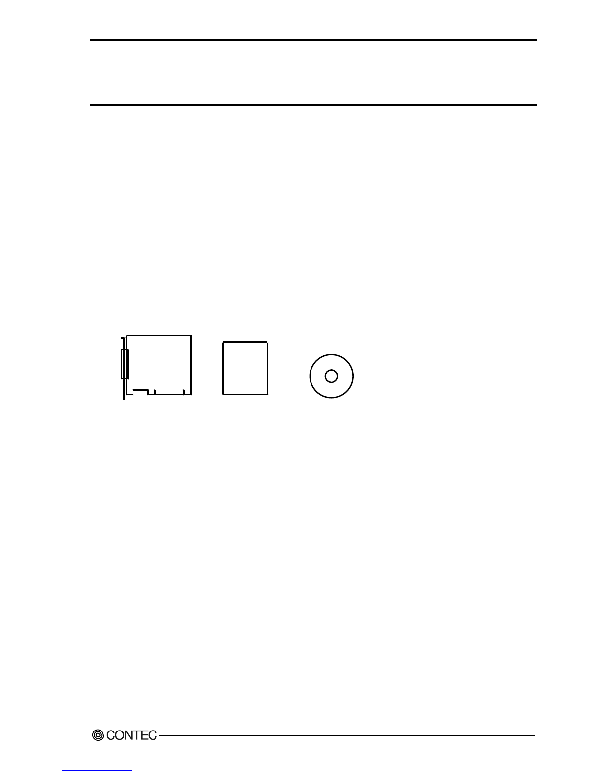
Product Configuration List
- Board
[GCOM-2C2-PCI, GCOM-4C2-PCI or GCOM-8C2-PCI]
- First step guide …1
- DRV-PAC(W32) (CD-ROM *1 ) …1
*1: The CD-ROM contains the driver software and User’s Guide (this guide).
CD-ROM
First step guide
Board
Page 3

ii
GCOM-2C2-PCI, GCOM-4C2-PCI, GCOM-8C2-PCI
Copyright
Copyright 2006 CONTEC Co., LTD. ALL RIGHTS RESERVED
No part of this document may be copied or reproduced in any form by any means without prior written
consent of CONTEC Co., LTD.
CONTEC Co., LTD. makes no commitment to update or keep current the information contained in this
document. The information in this document is subject to change without notice.
All relevant issues have been considered in the preparation of this document. Should you notice an
omission or any questionable item in this document, please feel free to notify CONTEC Co., LTD.
Regardless of the foregoing statement, CONTEC assumes no responsibility for any errors that may
appear in this document nor for results obtained by the user as a result of using this product.
Trademarks
MS, Microsoft , Windows and Windows NT are trademarks of Microsoft Corporation. Other brand and
product names are trademarks of their respective holder.
Page 4

GCOM-2C2-PCI, GCOM-4C2-PCI, GCOM-8C2-PCI
iii
Table of Contents
Copyright ............................................................................................................................................ ii
Trademarks ......................................................................................................................................... ii
Table of Contents............................................................................................................................... iii
1. BEFORE USING THE PRODUCT 1
About the Board.................................................................................................................................. 1
Features ........................................................................................................................................ 1
Support Software ......................................................................................................................... 2
Cable & Connector (Option) ...................................................................................................... 3
Accessories (Option) .................................................................................................................. 3
Customer Support ............................................................................................................................... 4
Web Site....................................................................................................................................... 4
Limited Three-Years Warranty .......................................................................................................... 4
How to Obtain Service ....................................................................................................................... 4
Liability............................................................................................................................................... 4
Safety Precautions .............................................................................................................................. 5
Safety Information ....................................................................................................................... 5
Handling Precautions................................................................................................................... 6
Environment................................................................................................................................. 7
Inspection ..................................................................................................................................... 7
Storage ......................................................................................................................................... 7
Disposal ....................................................................................................................................... 7
2. SETUP 9
What is Setup? .................................................................................................................................... 9
Using the Board under Windows Using the Standard COM Driver Software DRV-COM(WDM)
...................................................................................................................................................... 9
Step 1 Setting the Hardware ............................................................................................................. 10
Parts of the Board and Factory Defaults ................................................................................... 10
Setting the Board ID .................................................................................................................. 12
Setting the Supply Voltage ........................................................................................................ 12
Plugging the Board .................................................................................................................... 13
Plugging the Board .................................................................................................................... 13
Step 2 Installing the Hardware ......................................................................................................... 14
Turning on the PC...................................................................................................................... 14
Setting with the Add New Hardware Wizard............................................................................ 15
The check method of the completion of hardware installation ................................................. 17
Step 3 Initializing the Software........................................................................................................ 18
For use under Windows XP, Windows 2000 ............................................................................ 18
Step 4 Checking Operations with the Diagnosis Program............................................................... 19
Page 5

iv
GCOM-2C2-PCI, GCOM-4C2-PCI, GCOM-8C2-PCI
What is the Diagnosis Program? ............................................................................................... 19
Check Method............................................................................................................................ 19
Using the Diagnosis Program.................................................................................................... 20
Setup Troubleshooting...................................................................................................................... 22
If you have some problem ......................................................................................................... 22
3. EXTERNAL CONNECTION 23
In the case of GCOM-2C2-PCI ........................................................................................................ 24
Connecting directly to the port connector ................................................................................. 24
In the case of GCOM-4C2-PCI ........................................................................................................ 25
Converting the Interface Connector to 9-pin D-SUB, Male Connectors ................................. 25
Converting the Interface Connector to 25-pin D-SUB, Male Connectors ............................... 26
When using the CCU-78F/25M connection conversion unit .................................................... 27
Connecting directly to the port connector ................................................................................. 28
In the case of GCOM-8C2-PCI ........................................................................................................ 29
Converting the Interface Connector to 9-pin D-SUB, Male Connectors ................................. 29
Converting the Interface Connector to 25-pin D-SUB, Male Connectors ............................... 30
When using the CCU-78F/25M connection conversion unit .................................................... 31
Connecting directly to the port connector. ................................................................................ 32
Types of Cable and Example Connections....................................................................................... 34
4. FUNCTIONS 35
Communication Function ................................................................................................................. 35
Serial Data Transmission ........................................................................................................... 35
RS-232C Control Lines ............................................................................................................. 35
Send and Receive Data Buffers................................................................................................. 35
Setting the Baud Rate ................................................................................................................ 36
5. ABOUT SOFTWARE 39
About Sample programs ................................................................................................................... 39
Uninstalling the driver software....................................................................................................... 40
Windows XP, 2000 .................................................................................................................... 40
CD-ROM Directory Structure .......................................................................................................... 41
6. ABOUT HARDWARE 43
Hardware specification ..................................................................................................................... 43
Page 6

1. Before Using the Product
GCOM-2C2-PCI, GCOM-4C2-PCI, GCOM-8C2-PCI
1
1. Before Using the Product
This chapter provides information you should know before using the product.
About the Board
This board is a PCI bus interface board for performing RS-232C serial communications with external
devices.
The <GCOM-2C2-PCI> has
two serial ports per board
.
The <GCOM-4C2-PCI> has
four serial ports per board
.
The <GCOM-8C2-PCI> has
eight serial ports per board
.
You can use the standard COM driver software (DRV-PAC(W32)) supplied with the board to access the
serial ports as standard Windows COM ports.
Features
- Maximum communication speed = 921,600bps.
- The baud rate can be set independently for each channel, by software.
- Each channel is equipped with separate 128-byte FIFO buffers for transmit and receive.
- A maximum of 16 boards can be installed as configured in the range COM1 - COM256.
- Driver software is supplied to allow the serial ports to be used as standard Windows COM ports.
- The boards use the same easy-to-use 9-pin D-SUB connectors as are used on a PC.
Page 7

1. Before Using the Product
2
GCOM-2C2-PCI, GCOM-4C2-PCI, GCOM-8C2-PCI
Support Software
You should use CONTEC support software according to your purpose and development environment.
Standard COM Driver Software
DRV-COM(WDM)
The purpose of this software is to allow the CONTEC serial communication boards to be used under Windows in the
same way as the standard COM ports on the PC. By installing additional boards, you can use COM ports in the range
COM1 - COM256.
The boards can be used for all types of serial communications such as for remote access service (RAS) and
uninterruptible power supply (UPS) applications.
Under Windows, the serial ports can be accessed using the standard Win32 API communication routines (CreateFile( ),
WriteFile( ), ReadFile( ), and SetCommState( ), etc.) The serial ports are also compatible with the Visual Basic
communication control (MSComm).
< Operating environment >
OS Windows XP, 2000
CAUTION
The maximum number of COM ports able to be used depends on the configuration of your OS.
Page 8

1. Before Using the Product
GCOM-2C2-PCI, GCOM-4C2-PCI, GCOM-8C2-PCI
3
Cable & Connector (Option)
RS-232C Straight Cable with D-SUB9P (1.8m) : RSS-9M/F
RS-232C Cross Cable with D-SUB9P (1.8m) : RSC-9F
RS-232C Straight Cable with D-SUB25P (1.8m) : RSS-25M/F
RS-232C Cross Cable with D-SUB25P (1.8m) : RSC-25F
RS-232C Connection Conversion Straight Cable (25M→9F, 1.8m) : RSS-25M/9F
RS-232C Connection Conversion Straight Cable (25F→9M, 1.8m) : RSS-25F/9M
RS-232C Connection Conversion Cross Cable (25F→9F, 1.8m) : RSC-25F/9F
Connection Conversion Cable (37M→9M x 4, 250mm) : PCE37/9PS
Connection Conversion Cable (37M→25M x 4, 250mm) : PCE37/25PS
Connection Conversion Cable for RS-232C (37M→25M x 4, 450mm): COM-4M CABLE(PC)1
Connection Conversion Cable (78M→9M x 8, 1m) : PCE78/9PS
Connection Conversion Cable (78M→25M x 8, 1m) : PCE78/25PS
COM-8ch Board Optional Cable for CCU-78F/25M (2m) : RSS-78M
COM-4ch Board Optional Cable for CCU-78F/25M (2m) : RSS-78M/37M
Set of five 9-pin D-SUB (male) connectors : CN5-D9M
Set of five 9-pin D-SUB (female) connectors : CN5-D9F
Set of five 25-pin D-SUB (male) connectors : CN5-D25M
Set of five 25-pin D-SUB (female) connectors : CN5-D25F
Set of five 37-pin D-SUB (male) connectors : CN5-D37M
Set of five 78-pin D-SUB (male) connectors : CN5-D78M
Accessories (Option)
Connection Conversion Unit for RS-232C(78P→25P x 8) : CCU-78F/25M *1
*1 The option cable RSS-78M or RSS-78M/37M is needed.
* Check the CONTEC’s Web site for more information on these options.
Page 9

1. Before Using the Product
4
GCOM-2C2-PCI, GCOM-4C2-PCI, GCOM-8C2-PCI
Customer Support
CONTEC provides the following support services for you to use CONTEC products more efficiently and
comfortably.
Web Site
Japanese http://www.contec.co.jp/
English http://www.contec.com/
Chinese http://www.contec.com.cn/
Latest product information
CONTEC provides up-to-date information on products.
CONTEC also provides product manuals and various technical documents in the PDF.
Free download
You can download updated driver software and differential files as well as sample programs available in
several languages.
Note! For product information
Contact your retailer if you have any technical question about a CONTEC product or need its price,
delivery time, or estimate information.
Limited Three-Years Warranty
CONTEC Interface boards are warranted by CONTEC Co., LTD. to be free from defects in material and
workmanship for up to three years from the date of purchase by the original purchaser.
Repair will be free of charge only when this device is returned freight prepaid with a copy of the original
invoice and a Return Merchandise Authorization to the distributor or the CONTEC group office, from
which it was purchased.
This warranty is not applicable for scratches or normal wear, but only for the electronic circuitry and
original boards. The warranty is not applicable if the device has been tampered with or damaged through
abuse, mistreatment, neglect, or unreasonable use, or if the original invoice is not included, in which case
repairs will be considered beyond the warranty policy.
How to Obtain Service
For replacement or repair, return the device freight prepaid, with a copy of the original invoice. Please
obtain a Return Merchandise Authorization Number (RMA) from the CONTEC group office where you
purchased before returning any product.
* No product will be accepted by CONTEC group without the RMA number.
Liability
The obligation of the warrantor is solely to repair or replace the product. In no event will the warrantor
be liable for any incidental or consequential damages due to such defect or consequences that arise from
inexperienced usage, misuse, or malfunction of this device.
Page 10
1. Before Using the Product
GCOM-2C2-PCI, GCOM-4C2-PCI, GCOM-8C2-PCI
5
Safety Precautions
Understand the following definitions and precautions to use the product safely.
Safety Information
This document provides safety information using the following symbols to prevent accidents resulting in
injury or death and the destruction of equipment and resources. Understand the meanings of these labels
to operate the equipment safely.
DANGER
DANGER indicates an imminently hazardous situation which, if not avoided, will
result in death or serious injury.
WARNING
WARNING indicates a potentially hazardous situation which, if not avoided, could
result in death or serious injury.
CAUTION
CAUTION indicates a potentially hazardous situation which, if not avoided, may
result in minor or moderate injury or in property damage.
Page 11

1. Before Using the Product
6
GCOM-2C2-PCI, GCOM-4C2-PCI, GCOM-8C2-PCI
Handling Precautions
DANGER
Do not use the product where it is exposed to flammable or corrosive gas. Doing so may result in an
explosion, fire, electric shock, or failure.
CAUTION
- There are switches on the board that need to be set in advance. Be sure to check these before
installing the board.
- Only set the switches and jumpers on the board to the specified settings.
Otherwise, the board may malfunction, overheat, or cause a failure.
- Do not strike or bend the board. Doing so could damage the board.
Otherwise, the board may malfunction, overheat, cause a failure or breakage.
- Do not touch the board's metal plated terminals (edge connector) with your hands.
Otherwise, the board may malfunction, overheat, or cause a failure.
If the terminals are touched by someone's hands, clean the terminals with industrial alcohol.
- Do not install or remove the board to or from the slot while the computer's power is turned on.
Otherwise, the board may malfunction, overheat, or cause a failure.
Doing so could cause trouble. Be sure that the personal computer or the I/O expansion unit power is
turned off.
-
Make sure that your PC or expansion unit can supply ample power to all the boards installed.
Insufficiently energized boards could malfunction, overheat, or cause a failure.
-
The specifications of this product are subject to change without notice for enhancement and quality
improvement.
Even when using the product continuously, be sure to read the manual and understand the contents.
- Do not modify the product. CONTEC will bear no responsibility for any problems, etc., resulting
from modifying this product.
- Regardless of the foregoing statements, CONTEC is not liable for any damages whatsoever
(including damages for loss of business profits) arising out of the use or inability to use this
CONTEC product or the information contained herein.
Page 12
1. Before Using the Product
GCOM-2C2-PCI, GCOM-4C2-PCI, GCOM-8C2-PCI
7
Environment
Use this product in the following environment. If used in an unauthorized environment, the board may
overheat, malfunction, or cause a failure.
Operating temperature
0 - 50ºC
Humidity
10 - 90%RH (No condensation)
Corrosive gases
None
Floating dust particles
Not to be excessive
Inspection
Inspect the product periodically as follows to use it safely.
- Check that the board has
no dust or foreign matter adhering.
- The gold-plated leads of the bus connector
have no stain or corrosion.
- Check that the bus connector
of the board and its cable have
been plugged correctly.
Storage
When storing this product, keep it in its original packing form.
(1) Put the board in the storage bag.
(2) Wrap it in the packing material, then put it in the box.
(3) Store the package at room temperature at a place free from direct sunlight, moisture, shock,
vibration, magnetism, and static electricity.
Disposal
When disposing of the product, follow the disposal procedures stipulated under the relevant laws and
municipal ordinances.
Page 13

1. Before Using the Product
8
GCOM-2C2-PCI, GCOM-4C2-PCI, GCOM-8C2-PCI
Page 14

2. Setup
GCOM-2C2-PCI, GCOM-4C2-PCI, GCOM-8C2-PCI
9
2. Setup
This chapter explains how to set up the board.
What is Setup?
Setup means a series of steps to take before the product can be used.
Different steps are required for software and hardware
The setup procedure varies with the OS and applications used.
Using the Board under Windows
Using the Standard COM Driver Software DRV-COM(WDM)
This section describes the setup procedure to be performed before you can start developing application
programs for the board using the bundled CD-ROM “DRV-PAC(W32)”.
Taking the following steps sets up the software and hardware. You can use the diagnosis program later
to check whether the software and hardware function normally.
Step 1 Setting the Hardware
Step 2 Installing the Hardware
Step 3 Initializing the Software
Step 4 Checking Operations with the Diagnosis Program
On the CD-ROM, refer to the installation instructions files for each OS located in the
\DRVCOM\Pci\InstDoc
If Setup fails to be performed normally, see the “Setup Troubleshooting” section at the end of this
chapter.
Page 15
2. Setup
10
GCOM-2C2-PCI, GCOM-4C2-PCI, GCOM-8C2-PCI
Step 1 Setting the Hardware
This section describes how to set the board and plug it on your PC.
The board has some switches and jumper to be preset.
Check the on-board switches and jumpers before plugging the board into an expansion slot.
The board can be set up even with the factory defaults untouched. You can change board settings later.
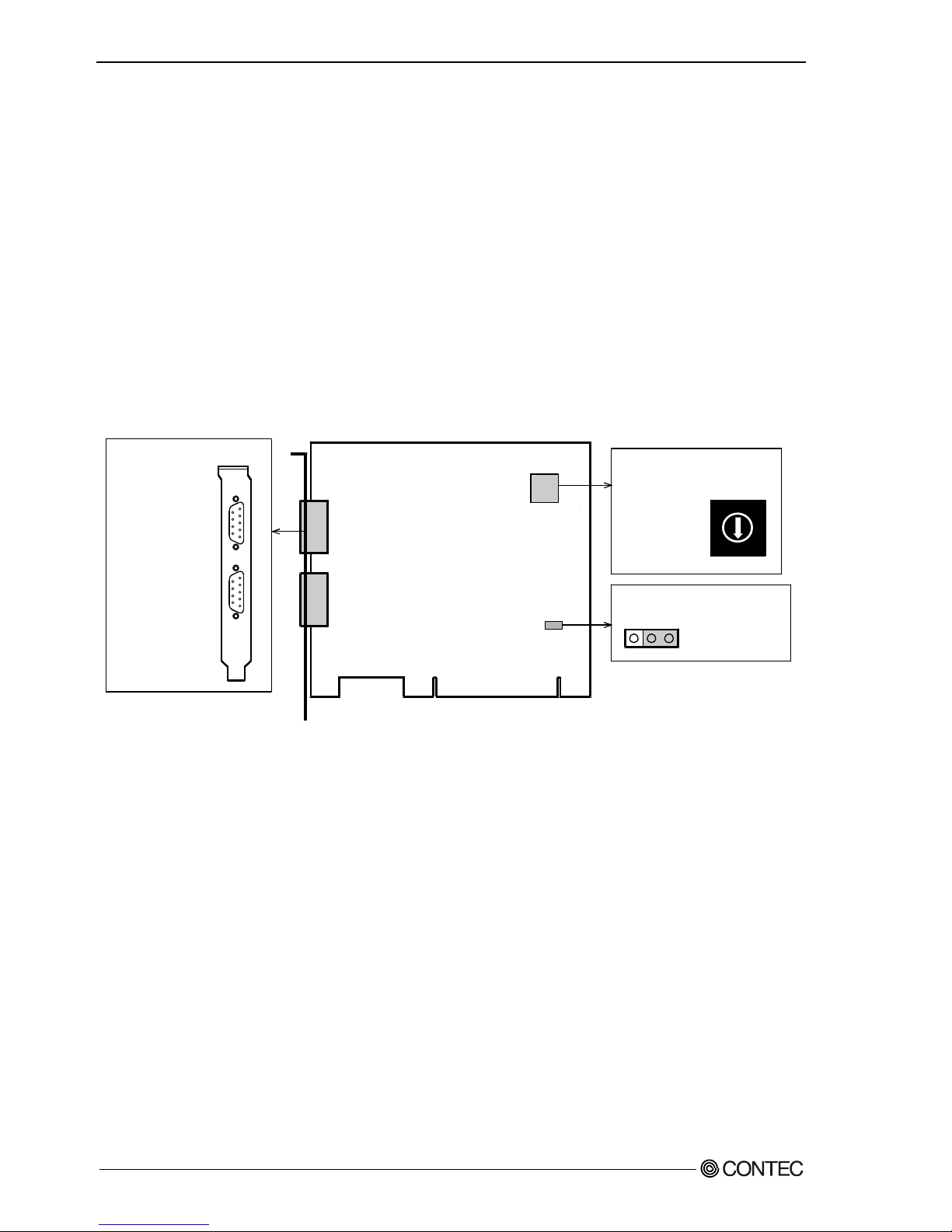
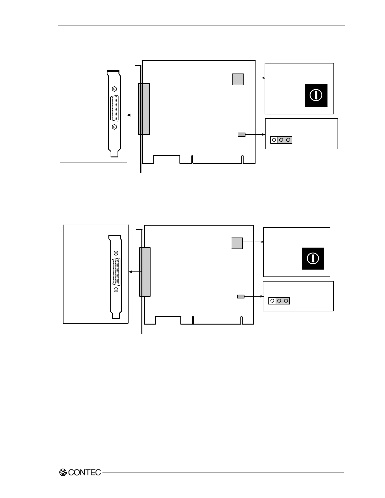
Parts of the Board and Factory Defaults
Figure 2.1 - Figure 2.3 shows the names of major parts on the board.
Note that the switch setting shown below is the factory default.
GCOM-2C2-PCI
- Interface connector
(CN1, CN2)
- BOARD ID Setting Switch
COM-2(PCI)H
123
JP1
JP1
SW1
BOARD ID
SW1
BOARD ID
(SW1)
0
1
2
3
4
5
6
7
9
A
B
C
D
E
F
8
- PCI bus slot
power voltage setting jumper
Figure 2.1. Component Locations < GCOM-2C2-PCI >
GCOM-2C2-PCI
Page 16
2. Setup
GCOM-2C2-PCI, GCOM-4C2-PCI, GCOM-8C2-PCI
11
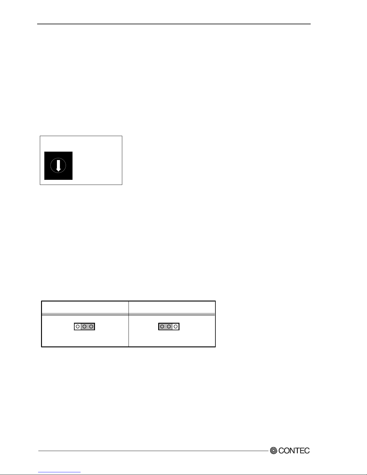
GCOM-4C2-PCI
- BOARD ID Setting Switch
- Interface connector
(CN1)
COM-4(PCI)H
JP1
SW1
BOARD ID
123
JP1
SW1
BOARD ID
(SW1)
0
1
2
3
4
5
6
7
9
A
B
C
D
E
F
8
- PCI bus slot
power voltage setting jumper
Figure 2.2. Component Locations < GCOM-4C2-PCI >
GCOM-8C2-PCI
- Interface connector
(CN1)
- BOARD ID Setting Switch
COM-8(PCI)H
JP1
SW1
BOARD ID
123
JP1
SW1
BOARD ID
(SW1)
0
1
2
3
4
5
6
7
9
A
B
C
D
E
F
8
- PCI bus slot
power voltage setting jumper
Figure 2.3. Component Locations < GCOM-8C2-PCI >
GCOM-4C2-PCI
GCOM-8C2-PCI
Page 17
2. Setup
12
GCOM-2C2-PCI, GCOM-4C2-PCI, GCOM-8C2-PCI
Setting the Board ID
If you install two or more boards on one personal computer, assign a different ID value to each of the
boards to distinguish them.
The board IDs can be set from 0 - Fh to identify up to sixteen boards.
If only one board is used, the original factory setting (Board ID = 0) should be used.
Setting Procedure
To set the board ID, use the rotary switch on the board. Turn the SW1 using, for example, a standard
screwdriver, to set the arrow to the board ID.
1
2
3
4
5
6
0
7
9
A
B
C
D
E
F
8
BOARD ID
SW1
(Board ID = 0)
Factory setting:
Figure 2.4. Board ID Settings (SW1)
Setting the Supply Voltage
Some PCI bus slots on the PC may supply power only at 3.3 V, where 5 V power is not available. In that
case, change the supply voltage of the board before use.
Setting method
To set the PCI bus slot supply voltage, use the on-board jumper.
When 5 V power is supplied, set the JP1 to the 2-3 connected state (factory default). If 5 V power is not
supplied, set the JP1 to the 1-2 connected state.
If outputting 5V power supply
(Factory setting)
123
JP1
123
JP1
If not outputting 5V power supply
(Factory setting)
Figure 2.5. Setting the Supply Voltage
Page 18

2. Setup
GCOM-2C2-PCI, GCOM-4C2-PCI, GCOM-8C2-PCI
13
Plugging the Board
(1) Before plugging the board, shut down the system, unplug the power code of your PC.
(2) Remove the cover from the PC so that the board can be mounted.
(3) Plug the board into an expansion slot.
(4) Attach the board bracket to the PC with a screw.
(5) Put the cover back into place.
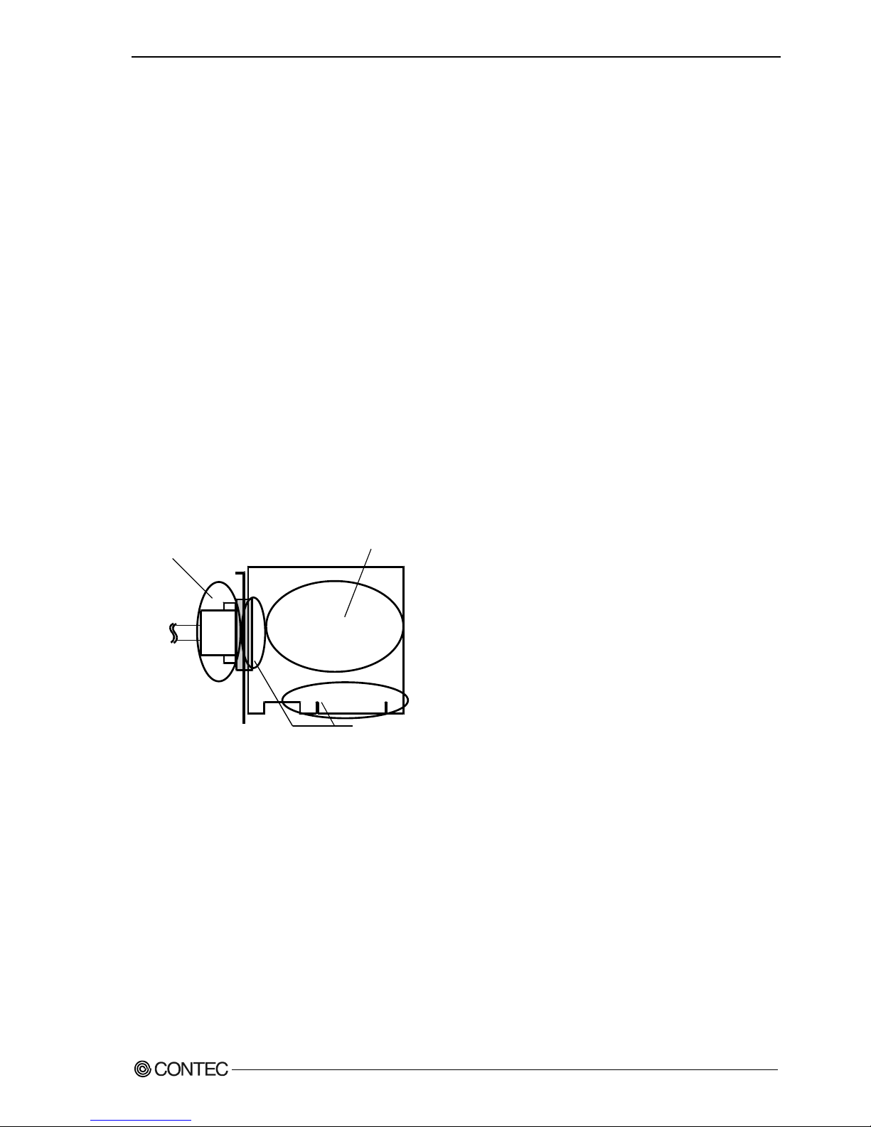
Applicable PCI bus slots
PCI bus slots used in PCs have keys to prevent 5V and 3.3V PCI bus boards from being accidentally
plugged into wrong bus slots. This board can be plugged into both of the 5V and 3.3V PCI bus slots.
AB
5V key
3.3V key
<PCI bus slot> <PCI bus board>
5-V PCI bus slot
3.3-V PCI bus slot
A :
B :
Slit for 5-V PCI bus slot
Slit for 3.3-V PCI bus slot
CAUTION
- Do not touch the board's metal plated terminals (edge connector) with your hands.
Otherwise, the board may malfunction, overheat, or cause a failure.
If the terminals are touched by someone's hands, clean the terminals with industrial alcohol.
- Do not install or remove the board to or from the slot while the computer's power is turned on.
Otherwise, the board may malfunction, overheat, or cause a failure.
Doing so could cause trouble. Be sure that the personal computer or the I/O expansion unit power is
turned off.
- Make sure that your PC or expansion unit can supply ample power to all the boards installed.
Insufficiently energized boards could malfunction, overheat, or cause a failure.
Page 19

2. Setup
14
GCOM-2C2-PCI, GCOM-4C2-PCI, GCOM-8C2-PCI
Step 2 Installing the Hardware
For using an expansion board under Windows, you have to let the OS detect the I/O addresses and IRQ to
be used by the board. The process is referred to as installing the hardware.
In the case of using two or more boards, make sure you install one by one with the Add New Hardware
Wizard.
Turning on the PC
Turn on the power to your PC.
CAUTION
- The board cannot be properly installed unless the resources (I/O addresses and interrupt level) for
the board can be allocated. Before attempting to install the board, first determine what PC resources
are free to use.
- The resources used by each board do not depend on the location of the PCI bus slot or the board itself.
If you remove two or more boards that have already been installed and then remount one of them on
the computer, it is unknown that which one of the sets of resources previously assigned to the two
boards is assigned to the remounted board. In this case, you must check the resource settings.
Page 20
2. Setup
GCOM-2C2-PCI, GCOM-4C2-PCI, GCOM-8C2-PCI
15
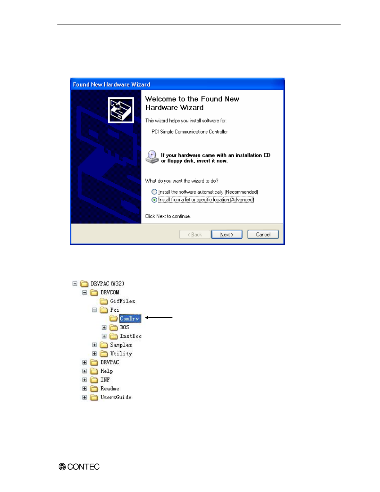
Setting with the Add New Hardware Wizard
(1) The “Add New Hardware Wizard” will be started.
Select “Install from a list or specific location”, then click on the [Next] button.
(2) Specify that folder on the CD-ROM which contains the setup information (INF) file to register the
board.
- Source folder \INF\WDM\Com
DRVCOM\Pci\ComDrv
Page 21
2. Setup
16
GCOM-2C2-PCI, GCOM-4C2-PCI, GCOM-8C2-PCI
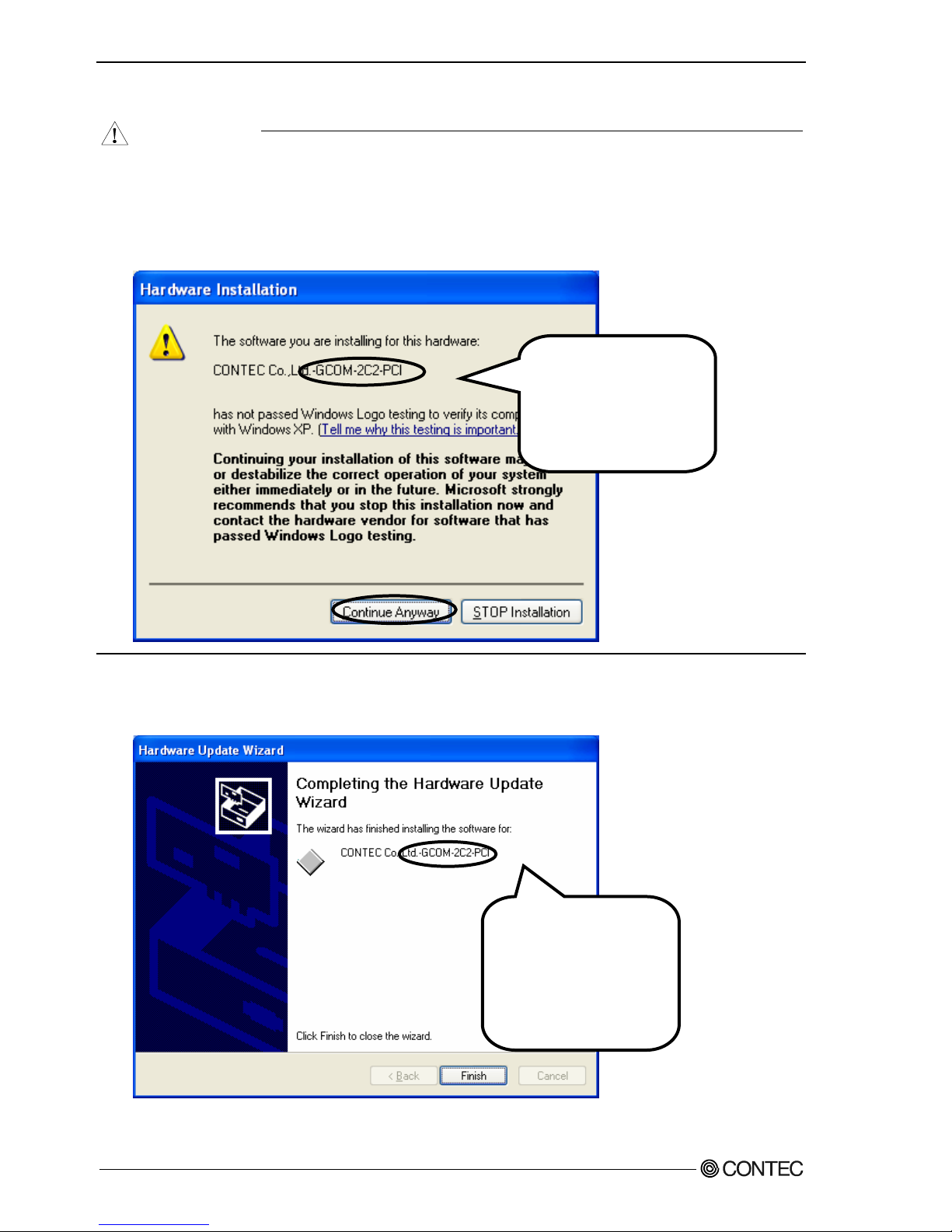
CAUTION
In Windows XP, the Hardware Wizard displays the following alert dialog box when you have
located the INF file. This dialog box appears, only indicating that the relevant driver has not passed
Windows Logo testing, and it can be ignored without developing any problem with the operation of
the board.
In this case, click on the [Continue Anyway] button.
(3) Installation of the "Communication Port" starts next. If prompted for a file by the OS, specify the
location of the setup information (INF) file, as described above.
You have now finished installing the hardware.
* The name of the board
you have just added is
displayed.
- GCOM-2C2-PCI
- GCOM-4C2-PCI
- GCOM-8C2-PCI
* The name of the board
you have just added is
displayed.
- GCOM-2C2-PCI
- GCOM-4C2-PCI
- GCOM-8C2-PCI
Page 22

2. Setup
GCOM-2C2-PCI, GCOM-4C2-PCI, GCOM-8C2-PCI
17
The check method of the completion of hardware installation
(1) Select "System" from "Control Panel" and open [Device Manager].
(2) Check that the names of the boards you are using are registered correctly in the [Multifunction
adapters] folder.
(3) Similarly, confirm that the COM ports have been added in the [Ports] folder.
Page 23
2. Setup
18
GCOM-2C2-PCI, GCOM-4C2-PCI, GCOM-8C2-PCI
Step 3 Initializing the Software
This assigns COM ports to the serial ports on the board. You can also change a previously assigned
COM port number to a different number.
For use under Windows XP, Windows 2000
On Windows XP and Windows 2000, the COM ports are already assigned by the hardware installation
step. Run Device Manager as described below if you wish to view or modify the COM port settings.
Start Device Manager
(1) Select "System" from "Control Panel" and start [Device Manager].
(2) Check that the new COM ports are displayed in the [Ports] folder.
Updating the Settings
(1) If you wish to change a port number, open the properties page for the port and click the
[Advanced…] button under [Port Settings].
(2) Use the [COM Port Number] combo box to modify the COM port number.
You have now finished installing the initial setting of Software.
* The name of the board
you have just added is
displayed.
- GCOM-2C2-PCI
- GCOM-4C2-PCI
- GCOM-8C2-PCI
Page 24

2. Setup
GCOM-2C2-PCI, GCOM-4C2-PCI, GCOM-8C2-PCI
19
Step 4 Checking Operations with the Diagnosis
Program
Use the diagnosis program to check that the board and driver software work normally, thereby you can
confirm that they have been set up correctly.
What is the Diagnosis Program?
These programs perform some simple checks on the board operation.
The following describes the procedure for testing using the serial communications diagnostic program
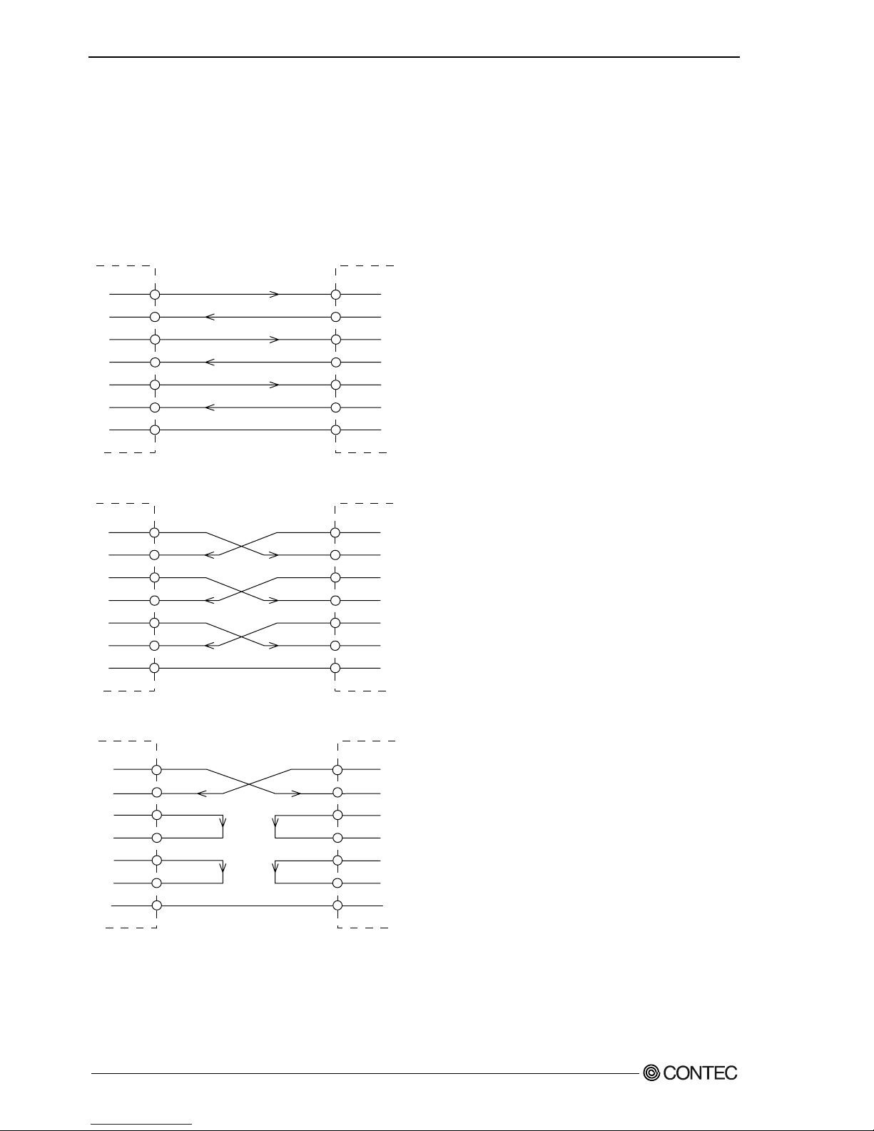
Check Method
Obtain an RS-232C cross cable or a loopback connector. If using a loopback connector, you can test a
single COM port on its own. The diagram below shows the connections for a loopback connector.
Wiring diagram for loopback connector
<9-pin>
Board side
3
2
7
8
4
6
TxD
RxD
RTS
CTS
DTR
DSR
Board side
TxD
RxD
RTS
CTS
DTR
DSR
<25-pin>
2
3
4
5
20
6
Page 25
2. Setup
20
GCOM-2C2-PCI, GCOM-4C2-PCI, GCOM-8C2-PCI
Using the Diagnosis Program
Run DRVCOM\Utility\CommChk\CommChk.exe
Communication Settings
COM Setup: Specify the number of the COM port you wish to test.
If connecting two COM ports via a cross cable, specify the respective COM ports in
[Device1] and [Device2].
If using a loopback connector, specify the same port number in both [Device1] and
[Device2].
Communication Settings: Specify the [Bits / Second], [Data bits] and other settings you wish to use.
Page 26

2. Setup
GCOM-2C2-PCI, GCOM-4C2-PCI, GCOM-8C2-PCI
21
Start test
Click the [Start] button to start the test using the specified conditions.
View test result
The test result is displayed in the [Message] window.
A successful completion message appears if the test completed OK.
Page 27

2. Setup
22
GCOM-2C2-PCI, GCOM-4C2-PCI, GCOM-8C2-PCI
Setup Troubleshooting
If you have some problem
Contact your retailer.
Page 28

3. External Connection
GCOM-2C2-PCI, GCOM-4C2-PCI, GCOM-8C2-PCI
23
3. External Connection
This chapter describes the interface connectors on the board.
Check the information available here when connecting an external device.
In addition to connecting directly to the connector on the board, you can also connect external devices
via a connection conversion cable or connection con. version unit.
- Connecting directly to the port connector.
- Using a connection conversion cable (GCOM-4C2-PCI, GCOM-8C2-PCI)
- Using a connection conversion unit (GCOM-4C2-PCI, GCOM-8C2-PCI)
Page 29

3. External Connection
24
GCOM-2C2-PCI, GCOM-4C2-PCI, GCOM-8C2-PCI
In the case of GCOM-2C2-PCI
Connecting directly to the port connector
If connecting an external device directly from the connector on the board, use a cable purchased
separately. If making your own cable, use a CN5-D9F or equivalent connector.
Pin Assignment
CN1
CN2
1
6
5
9
6
9
1
5
- Connector used
DELC-J9PAF-20L9 (mfd. by JAE, Male)equivalent
- Applicable connector
17JE-13090-02(D8C) (mfd. by DDK, Male)
CN5-D9F (mfd. by CONTEC, Male) (Five connector set)
Screw nut: UNC#4-40(inch screw)
Figure 3.1. Interface Connector < GCOM-2C2-PCI >
CN1
1
2
3
4
5
6
7
8
9
DCD1 Data Carrier Detect
RxD1 Receive Data
TxD1 Transmit Data
DTR1 Data Terminal Ready
SG1 Signal Ground
Data Set Ready DSR1
Request to Send RTS1
Clear to Send CTS1
Ring Indicator RI1
CN2
1
2
3
4
5
6
7
8
9
DCD2 Data Carrier Detect
RxD2 Receive Data
TxD2 Transmit Data
DTR2 Data Terminal Ready
SG2 Signal Ground
Data Set Ready DSR2
Request to Send RTS2
Clear to Send CTS2
Ring Indicator RI2
Figure 3.2. Pin Assignments of Interface Connector < GCOM-2C2-PCI >
Cable (Option)
RS-232C Straight Cable with D-SUB9P (1.8m) RSS-9M/F
RS-232C Cross Cable with D-SUB9P (1.8m) RSC-9F
Page 30

3. External Connection
GCOM-2C2-PCI, GCOM-4C2-PCI, GCOM-8C2-PCI
25
In the case of GCOM-4C2-PCI
When using a GCOM-4C2-PCI, an alternative to connecting an external device directly to the connector
on the board is to use a connection conversion cable or connection conversion unit.
Converting the Interface Connector to 9-pin D-SUB,
Male Connectors
Use a PCE37/9PS connection conversion cable (purchased separately) to connect to external devices
after dividing into four 9-pin D-SUB male connector channels.
Use separately purchased 9-pin D-SUB or equivalent cables to connect from the four individual
connectors.
- Connector used
37-pin D-SUB, male connector
Thumb screw :
UNC #4-40 (inch screw)
- Cable
9-conductor shielded cable
Cable length : 250mm
Conductor size : AWG#28
- Connector used
9-pin D-SUB, male connector
Thumb screw : UNC#4-40(inch screw)
- Applicable connectors
17JE-13090-02(D8C) (mfd. by DDK, Female)
.
.
.
SG 1
DTR 1
TxD 1
RxD 1
DCD 1
9
8
7
6
RI 1
CTS 1
RTS 1
DSR 1
5
4
3
2
1
CH1
SG 4
DTR 4
TxD 4
RxD 4
DCD 4
9
8
7
6
RI 4
CTS 4
RTS 4
DSR 4
5
4
3
2
1
CH4
CH1
CH2
CH3
CH4
Figure 3.3. Specification of “PCE37/9PS”
Connection conversion cable (Option)
Connection Conversion Cable (37M→9M x 4, 250mm) PCE37/9PS
Cable (Option)
RS-232C Straight Cable with D-SUB9P (1.8m) RSS-9M/F
RS-232C Cross Cable with D-SUB9P (1.8m) RSC-9F
Page 31

3. External Connection
26
GCOM-2C2-PCI, GCOM-4C2-PCI, GCOM-8C2-PCI
Converting the Interface Connector to 25-pin D-SUB,
Male Connectors
Use a PCE37/25PS connection conversion cable (purchased separately) to connect to external devices
after dividing into four 25-pin D-SUB male connector channels.
Use separately purchased 25-pin D-SUB or equivalent cables to connect from the four individual
connectors.
- Connector used
25-pin D-SUB, male connector
Thumb screw : UNC#4-40(inch screw)
- Applicable connectors
17JE-13250-02(D8C)
(mfd. by DDK, Female)
- Cable
9-conductor shielded cable
Cable length : 250mm
Conductor size : AWG#28
- Connector used
37-pin D-SUB, male connector
Thumb screw :
UNC #4-40 (inch screw)
CH1
CH2
CH3
CH4
.
.
.
N.C.
N.C.
N.C.
N.C.
N.C.
DCD 4
SG 4
DSR 4
CTS 4
RTS 4
RxD 4
TxD 4
N.C.
25
24
23
22
21
20
19
18
17
16
15
14
N.C.
N.C.
N.C.
RI 4
N.C.
DTR 4
N.C.
N.C.
N.C.
N.C.
N.C.
N.C.
13
12
11
10
9
8
7
6
5
4
3
2
1
CH4
25
24
23
22
21
20
19
18
17
16
15
14
N.C.
N.C.
N.C.
N.C.
N.C.
DCD 1
SG1
DSR 1
CTS 1
RTS 1
RxD 1
TxD 1
N.C.
N.C.
N.C.
N.C.
RI 1
N.C.
DTR 1
N.C.
N.C.
N.C.
N.C.
N.C.
N.C.
13
12
11
10
9
8
7
6
5
4
3
2
1
CH1
Figure 3.4. Specification of “PCE37/25PS”
Connection conversion cable (Option)
Connection Conversion Cable (37M→25M x 4, 250mm) PCE37/25PS
Connection Conversion Cable for RS-232C (37M→25M x 4, 450mm) COM-4M CABLE(PC)1
Cable (Option)
RS-232C Straight Cable with D-SUB25P (1.8m) RSS-25M/F
RS-232C Cross Cable with D-SUB25P (1.8m) RSC-25F
RS-232C Connection Conversion Straight Cable (25M→9F, 1.8m) RSS-25M/9F
RS-232C Connection Conversion Straight Cable (25F→9M, 1.8m) RSS-25F/9M
RS-232C Connection Conversion Cross Cable (25F→9F, 1.8m) RSC-25F/9F
Page 32
3. External Connection
GCOM-2C2-PCI, GCOM-4C2-PCI, GCOM-8C2-PCI
27
When using the CCU-78F/25M connection conversion unit
Use a CCU-78F/25M connection conversion unit (purchased separately) to connect to external devices
after dividing into four 25-pin D-SUB male connector channels.
This method has the following features.
- The unit can be fitted to a DIN rail using a separately purchased ADP-1 DIN rail adapter.
- The unit can be fitted to a wall or similar using screws.
- By connecting an external power supply, the unit can output a power supply from the 25-pin D-SUB
connector.
Use a separately purchased 25-pin D-SUB connector cable to connect from the four individual
connectors.
Figure 3.5. Connection Procedure
1
2
3
4
5
6
7
8
9
10
11
12
13
14
15
16
17
18
19
20
21
22
23
24
25
- Connector used
25-pin D-SUB, male connector
Thumb screw: UNC#4-40(inch screrw)
- Applicable
17JE-13250-02(D8C)(mfd. by DDK, Female)
CN5-D25F (mfd. by CONTEC, Female) (Five connector set)
* A power supply output is referred to.
N.C.
N.C.
N.C.
N.C.
N.C.
N.C.
Data Terminal Ready DTR
N.C.
Ring Indicator RI
N.C.
N.C.
Power supply output *
FG
TxD Transmit Data
RxD Receive Data
RTS Request to Send
CTS Clear to Send
DSR Data Set Ready
SG Signal Ground
DCD Data Carrier Detect
N.C.
N.C.
N.C.
N.C.
N.C.
Figure 3.6. Pin Assignments of Interface Connector
Page 33
3. External Connection
28
GCOM-2C2-PCI, GCOM-4C2-PCI, GCOM-8C2-PCI
Connection conversion cable & connection conversion unit (Option)
Connection Conversion Unit for RS-232C(78P→25P x 8) CCU-78F/25M
COM-4ch Board Optional Cable for CCU-78F/25M (2m) RSS-78M/37M
Connection cable (Option)
RS-232C Straight Cable with D-SUB25P (1.8m) RSS-25M/F
RS-232C Cross Cable with D-SUB25P (1.8m) RSC-25F
RS-232C Connection Conversion Straight Cable (25M→9F, 1.8m) RSS-25M/9F
RS-232C Connection Conversion Straight Cable (25F→9M, 1.8m) RSS-25F/9M
RS-232C Connection Conversion Cross Cable (25F→9F, 1.8m) RSC-25F/9F
Connecting directly to the port connector
If connecting an external device directly from the connector on the board, use a CN5-D9F or equivalent
connector.
Pin Assignment
37
20
19
1
- Connector used
37-pin D-SUB, male connector
DCLC-J37SAF-20L9 (mfd. by JAE)equivalent
- Applicable connector
17JE-23370-02(D8C) (mfd. by DDK, Male)
FDCD-37P (mfd. by HIROSE, Male)
DC-37P-N (mfd. by JAE, Male)
CN5-D37M (mfd. by CONTEC, Male) (Five connector set)
Screw nut: UNC#4-40(inch screw)
Figure 3.7. Interface Connector < GCOM-4C2-PCI >
19
18
17
16
15
14
13
12
11
10
9
8
7
6
5
4
3
2
1
TxD1 CH1 Transmit Data 1
RTS1 CH1 Request to Send 1
DSR1 CH1 Data Set Ready 1
DTR1 CH1 Data Terminal Ready 1
RI1 CH1 Ring Indicator 1
RxD2 CH2 Receive Data 2
CTS2 CH2 Clear to Send 2
SG2 CH2 Signal Ground 2
DCD2 CH2 Data Carrier Detect 2
TxD4 CH4 Transmit Data 4
RTS4 CH4 Request to Send 4
DSR4 CH4 Data Set Ready 4
DTR4 CH4 Data Terminal Ready 4
RI4 CH4 Ring Indicator 4
RxD3 CH3 Receive Data 3
CTS3 CH3 Clear to Send 3
SG3 CH3 Signal Ground 3
DCD3 CH3 Data Carrier Detect 3
N.C.
37
36
35
34
33
32
31
30
29
28
27
26
25
24
23
22
21
20
CH1 Receive Data 1 RxD1
CH1 Clear to Send 1 CTS1
CH1 Signal Ground 1 SG1
CH1 Data Carrier Detect 1 DCD1
CH2 Transmit Data 2 TxD2
CH2 Request to Send 2 RTS2
CH2 Data Set Ready 2 DSR2
CH2 Data Terminal Ready 2 DTR2
CH2 Ring Indicator 2 RI2
CH4 Receive Data 4 RxD4
CH4 Clear to Send 4 CTS4
CH4 Signal Ground 4 SG4
CH4 Data Carrier Detect 4 DCD4
CH3 Transmit Data 3 TxD3
CH3 Request to Send 3 RTS3
CH3 Data Set Ready 3 DSR3
CH3 Data Terminal Ready 3 DTR3
CH3 Ring Indicator 3 RI3
CN1
Figure 3.8. Pin Assignments of Interface Connector < GCOM-4C2-PCI >
Page 34
3. External Connection
GCOM-2C2-PCI, GCOM-4C2-PCI, GCOM-8C2-PCI
29
In the case of GCOM-8C2-PCI
When using a GCOM-8C2-PCI, an alternative to connecting an external device directly to the connector
on the board is to use a connection conversion cable or connection conversion unit.
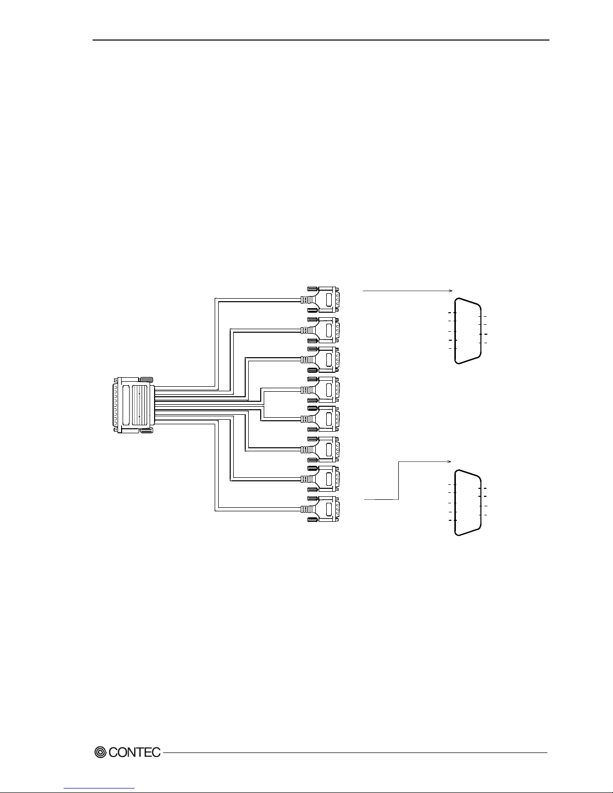
Converting the Interface Connector to 9-pin D-SUB,
Male Connectors
Use a PCE78/9PS connection conversion cable (purchased separately) to connect to external devices
after dividing into eight 9-pin D-SUB male connector channels.
Use separately purchased 9-pin D-SUB or equivalent cables to connect from the eight individual
connectors.
CH1
CH2
CH3
CH4
CH5
CH6
CH7
CH8
5
4
3
2
1
SG 1
DTR 1
TxD 1
RxD 1
DCD 1
9
8
7
6
RI 1
CTS 1
RTS 1
DSR 1
- Cable
9-conductor shielded cable
Cable length : 1m
Conductor size : AWG#28
- Connector used
9-pin D-SUB, male connector
Thumb screw : UNC#4-40(inch screw)
- Applicable connectors
17JE-13090-02(D8C)
(mfd. by DDK, Female)
- Connector used
78-pin D-SUB, male connector
Thumb screw :
UNC #4-40 (inch screw
.
.
.
.
.
.
.
.
.
CH1
CH8
5
4
3
2
1
SG 8
DTR 8
TxD 8
RxD 8
DCD 8
9
8
7
6
RI 8
CTS 8
RTS 8
DSR 8
Figure 3.9. Specification of “PCE78/9PS”
Connection conversion cable (Option)
Connection Conversion Cable (78P→25P x 8) PCE78/9PS
Connection cable (Option)
RS-232C Straight Cable with D-SUB9P (1.8m) RSS-9M/F
RS-232C Cross Cable with D-SUB9P (1.8m) RSC-9F
Page 35
3. External Connection
30
GCOM-2C2-PCI, GCOM-4C2-PCI, GCOM-8C2-PCI
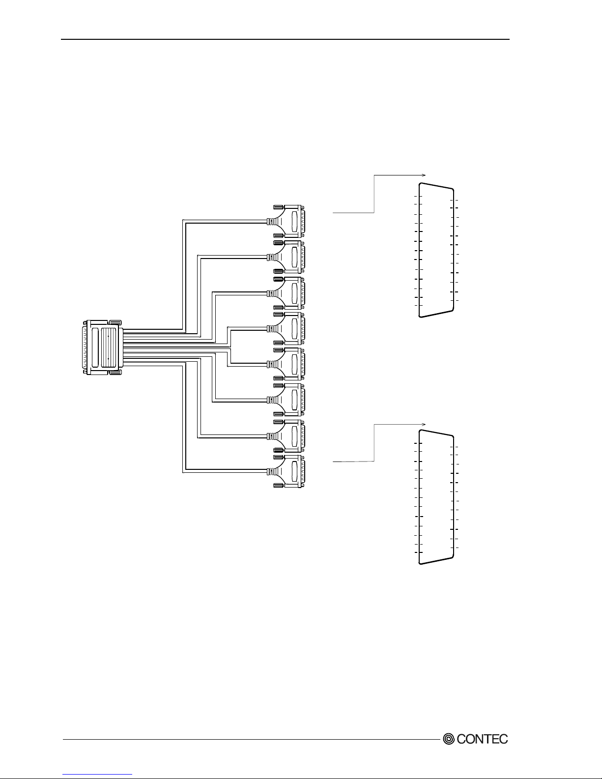
Converting the Interface Connector to 25-pin D-SUB,
Male Connectors
Use a PCE78/25PS connection conversion cable (purchased separately) to connect to external devices
after dividing into eight 25-pin D-SUB male connector channels.
Use separately purchased 25-pin D-SUB or equivalent cables to connect from the eight individual
connectors.
CH1
CH2
CH3
CH4
CH5
CH6
CH7
CH8
N.C.
N.C.
N.C.
N.C.
N.C.
DCD 8
SG 8
DSR 8
CTS 8
RTS 8
RxD 8
TxD 8
N.C.
25
24
23
22
21
20
19
18
17
16
15
14
N.C.
N.C.
N.C.
RI 8
N.C.
DTR 8
N.C.
N.C.
N.C.
N.C.
N.C.
N.C.
13
12
11
10
9
8
7
6
5
4
3
2
1
CH8
N.C.
N.C.
N.C.
N.C.
N.C.
DCD 1
SG1
DSR 1
CTS 1
RTS 1
RxD 1
TxD 1
N.C.
25
24
23
22
21
20
19
18
17
16
15
14
N.C.
N.C.
N.C.
RI 1
N.C.
DTR 1
N.C.
N.C.
N.C.
N.C.
N.C.
N.C.
13
12
11
10
9
8
7
6
5
4
3
2
1
CH1
- Cable
9-conductor shielded cable
Cable length : 1m
Conductor size : AWG#28
.
.
.
.
.
.
.
.
.
- Connector used
78-pin D-SUB, male connector
Thumb screw :
UNC #4-40 (inch screw)
- Connector used
9-pin D-SUB, male connector
Thumb screw : UNC#4-40(inch screw)
- Applicable connectors
17JE-13090-02(D8C)
(mfd. by DDK, Female)
Figure 3.10. Specification of “PCE78/25PS”
Connection conversion cable (Option)
Connection Conversion Cable (78P→25P x 8) PCE78/25PS
Connection cable (Option)
RS-232C Straight Cable with D-SUB25P (1.8m) RSS-25M/F
RS-232C Cross Cable with D-SUB25P (1.8m) RSC-25F
RS-232C Connection Conversion Straight Cable (25M→9F, 1.8m) RSS-25M/9F
RS-232C Connection Conversion Straight Cable (25F→9M, 1.8m) RSS-25F/9M
RS-232C Connection Conversion Cross Cable (25F→9F, 1.8m) RSC-25F/9F
Page 36
3. External Connection
GCOM-2C2-PCI, GCOM-4C2-PCI, GCOM-8C2-PCI
31
When using the CCU-78F/25M connection conversion unit
Use a CCU-78F/25M connection conversion unit (purchased separately) to connect to external devices
after dividing into eight 25-pin D-SUB male connector channels.
This method has the following features.
- The unit can be fitted to a DIN rail using a separately purchased ADP-1 DIN rail adapter.
- The unit can be fitted to a wall or similar using screws.
- By connecting an external power supply, the unit can output a power supply from the 25-pin D-SUB
connector.
Use a separately purchased 25-pin D-SUB connector cable to connect from the eight individual
connectors.
Figure 3.11. Connection Procedure
1
2
3
4
5
6
7
8
9
10
11
12
13
14
15
16
17
18
19
20
21
22
23
24
25
- Connector used
25-pin D-SUB, male connector
Thumb screw: UNC#4-40(inch screrw)
- Applicable
17JE-13250-02(D8C)(mfd. by DDK, Female)
CN5-D25F (mfd. by CONTEC, Female) (Five connector set)
* A power supply output is referred to.
N.C.
N.C.
N.C.
N.C.
N.C.
N.C.
Data Terminal Ready DTR
N.C.
Ring Indicator RI
N.C.
N.C.
Power supply output *
FG
TxD Transmit Data
RxD Receive Data
RTS Request to Send
CTS Clear to Send
DSR Data Set Ready
SG Signal Ground
DCD Data Carrier Detect
N.C.
N.C.
N.C.
N.C.
N.C.
Figure 3.12. Pin Assignments of Interface Connector
Page 37
3. External Connection
32
GCOM-2C2-PCI, GCOM-4C2-PCI, GCOM-8C2-PCI
Connection conversion cable & connection conversion unit (Option)
Connection Conversion Unit for RS-232C(78P→25P x 8) CCU-78F/25M
COM-8ch Board Optional Cable for CCU-78F/25M (2m) RSS-78M
Connection cable (Option)
RS-232C Straight Cable with D-SUB25P (1.8m) RSS-25M/F
RS-232C Cross Cable with D-SUB25P (1.8m) RSC-25F
RS-232C Connection Conversion Straight Cable (25M→9F, 1.8m) RSS-25M/9F
RS-232C Connection Conversion Straight Cable (25F→9M, 1.8m) RSS-25F/9M
RS-232C Connection Conversion Cross Cable (25F→9F, 1.8m) RSC-25F/9F
Connecting directly to the port connector.
If connecting an external device directly from the connector on the board, use a CN5-D78M or
equivalent connector.
Pin Assignment
- Connector used
78-pin D-SUB, female connector
DV11603G4 (mfd. by FOXCONN)equivalent
- Applicable connector
CN5-D78M (mfd. by CONTEC, Male) (Five connector set)
59
39
78
20
60 1
40 21
Screw nut: UNC#4-40(inch screw)
Figure 3.13. Interface Connector < GCOM-8C2-PCI >
Page 38

3. External Connection
GCOM-2C2-PCI, GCOM-4C2-PCI, GCOM-8C2-PCI
33
Pin No. Signal
name
Pin No. Signal
name
Pin No. Signal
name
Pin No. Signal
name
78 N.C. 59 DSR 1 39 RTS 1 20 TxD 1
77 SG 1 58 DCD 1 38 CTS 1 19 RxD 1
76 N.C. 57 RI 1 37 DSR 2 18 DTR 1
75 SG 2 56 DCD 2 36 RTS 2 17 TxD 2
74 RI 2 55 DTR 2 35 CTS 2 16 RxD 2
73 N.C. 54 DSR 3 34 RTS 3 15 TxD 3
72 SG 3 53 DCD 3 33 CTS 3 14 RxD 3
71 DSR 4 52 RI 3 32 RTS 4 13 DTR 3
70 SG 4 51 DCD 4 31 CTS 4 12 TxD 4
69 RI 4 50 DTR 4 30 DSR 5 11 RxD 4
68 SG 5 49 DCD 5 29 RTS 5 10 TxD 5
67 RI 5 48 DTR 5 28 CTS 5 9 RxD 5
66 N.C. 47 DSR 6 27 RTS 6 8 TxD 6
65 SG 6 46 DCD 6 26 CTS 6 7 RxD 6
64 N.C. 45 RI 6 25 DSR 7 6 DTR 6
63 SG 7 44 DCD7 24 RTS 7 5 TxD 7
62 RI 7 43 DTR 7 23 CTS 7 4 RxD 7
61 N.C. 42 DSR 8 22 RTS 8 3 TxD 8
60 SG 8 41 DCD 8 21 CTS 8 2 RxD 8
40 RI 8
CN1
1214060
20
395978
1 DTR 8
Figure 3.14. Pin Assignments of Interface Connector < GCOM-8C2-PCI >
The connector used for COM8-(PCI)H has a wide interpin space and is highly reliable.
In the case of a PC with a narrow slot opening, a gap might be created as wide as the
thickness of the sheet metal of the PC when an external cable is connected, preventing
the connector from being fitted properly. If the thickness of the sheet metal is less than
1.5mm (typically about 1.0mm), simply tighten the adjusting screw located on the side
of the connector to install it properly. The connector should function without a problem.
Thickness of the sheet metal
(about 1.0mm)
PC case
Bracket
Circuit
boards
Thickness of
the bracket (0.8mm)
The slot
opening width
Cable side
connectors
Figure 3.15. The note about external connection < GCOM-8C2-PCI >
GCOM-8C2-PCI
Page 39
3. External Connection
34
GCOM-2C2-PCI, GCOM-4C2-PCI, GCOM-8C2-PCI
Types of Cable and Example Connections
The connector used for GCOM-8C2-PCI has a wide interpin space and is highly reliable. In the case of
a PC with a narrow slot opening, a gap might be created as wide as the thickness of the sheet metal of the
PC when an external cable is connected, preventing the connector from being fitted properly. If the
thickness of the sheet metal is less than 1.5mm (typically about 1.0mm), simply tighten the adjusting
screw located on the side of the connector to install it properly. The connector should function without
a problem.
TxD
RxD
RTS
CTS
DTR
DSR
SG
TxD
RxD
RTS
CTS
DTR
DSR
SG
(Transmit Data)
(Receive Data)
(Request to Send)
(Clear to Send)
(Data Terminal Ready)
(Data Set Ready)
(Signal Ground)
External device
Figure 3.16. Example Connection to a Modem (Straight cable)
TxD
RxD
RTS
CTS
DTR
DSR
SG
TxD
RxD
RTS
CTS
DTR
DSR
SG
External device
Figure 3.17. Example Connection to a PC (Cross cable)
TxD
RxD
RTS
CTS
DTR
DSR
SG
TxD
RxD
RTS
CTS
DTR
DSR
SG
External device
Figure 3.18. Example Connection to a Device
Page 40

4. Functions
GCOM-2C2-PCI, GCOM-4C2-PCI, GCOM-8C2-PCI
35
4. Functions
This section describes the functions of the board.
Communication Function
Serial Data Transmission
Sends and receives data in accordance with the RS-232C standard.
The baud rate for each channel can be set independently in the range 2
-
921,600bps by software.
RS-232C Control Lines
All ports include the RTS, CTS, DTR, and DSR control lines.
The lines can be controlled or monitored by software from the application
Send and Receive Data Buffers
Each channel has a separate 128-byte send and 128-byte receive buffer.
The buffers operate as FIFO buffers and help reduce the load on the CPU for high-speed
communications or system operation.
The data buffer settings (Use FIFO ON/OFF and FIFO trigger size) are set by the Device Manager (on
Windows XP and 2000).
The FIFO trigger size specifies the data buffer size and determines the timing for generating hardware
interrupts.
Setting a large FIFO trigger size lightens the load on the CPU by reducing the number of hardware
interrupts generated by sending or receiving data.
However, as data is not actually sent or received until a certain amount of data has accumulated, the
timing at which the data reaches the opposing device is slightly delayed. Similarly, there is also a delay
in the timing between data being received and the data being passed the application.
Alternatively, setting a small FIFO trigger size or disabling FIFO operation increases the speed of data
sending and receiving but increases the load on the CPU and risks received data being missed.
As the FIFO buffer size is variable, you can adjust this setting to achieve optimum performance for your
system.
Page 41

4. Functions
36
GCOM-2C2-PCI, GCOM-4C2-PCI, GCOM-8C2-PCI
Setting the Baud Rate
The output baud rate can be set by setting the appropriate value to the Baud Rate Generator register. The
available setting range depends on which clock mode is used.
Clock 3 mode: 15
-
921,600bps
Clock 2 mode: 8
-
460,800bps
Clock 1 mode: 4
-
230,400bps
Clock 0 mode: 2
-
115,200bps
However, some baud rate values do not have a corresponding Baud Rate Generator register setting. If
the result of substituting the baud rate into the equation below is an integer, then that baud rate can be set.
If the result contains a fractional part, the baud rate cannot be set.
Clock 3 mode
921600 ÷ Desired baud rate = Division register setting value
Ex.) 921600 ÷ 9600bps = 96 (As the result is an integer, this baud rate can be set.)
921600 ÷ 128000bps = 7.2 (As the result contains a fractional part, this baud rate cannot be set.)
Clock 2 mode
460800 ÷ Desired baud rate = Division register setting value
Ex.) 460800 ÷ 9600bps = 48 (As the result is an integer, this baud rate can be set.)
460800 ÷ 128000bps = 3.6 (As the result contains a fractional part, this baud rate cannot be set.)
Clock 1 mode
230400 ÷ Desired baud rate = Division register setting value
Ex.) 230400 ÷ 9600bps = 24 (As the result is an integer, this baud rate can be set.)
230400 ÷ 128000bps = 1.8 (As the result contains a fractional part, this baud rate cannot be set.)
Clock 0 mode
115200 ÷ Desired baud rate = Division register setting value
Ex.) 115200 ÷ 9600bps = 12 (As the result is an integer, this baud rate can be set.)
115200 ÷ 76800bps = 1.5 (As the result contains a fractional part, this baud rate cannot be set.)
Page 42

4. Functions
GCOM-2C2-PCI, GCOM-4C2-PCI, GCOM-8C2-PCI
37
Refer to the following baud rate setting examples. Baud rates other than those listed
below can also be set if they produce a valid setting value in the equation described above.
Table 4.1. Baud Rate Generator Programming Table
Clock 0 mode
(1.8432MHz)
Clock 1 mode
(3.6864MHz)
Clock 2 mode
(7.3728MHz)
Clock 3 mode
(14.7456MHz)
Output
baud rate
Baud Rate
Generator
register
Setup
error
(%)
Baud Rate
Generator
register
Setup
error
(%)
Baud Rate
Generator
register
Setup
error
(%)
Baud Rate
Generator
register
Setup
error
(%)
2 57600 ---
4 28800 --- 57600 ---
5 23040 --- 46080 ---
8 14400 --- 28800 --- 57600 ---
15 7680 --- 15360 --- 30720 --- 61440 ---
50 2304 --- 4608 --- 9216 --- 18432 ---
75 1536 --- 3072 --- 6144 --- 12288 ---
110 1047 0.026 2094 0.026 4189 0.0022 8378 0.0022
134.5 857 0.058 1713 0.0006 3426 0.0006 6852 0.0006
150 768 --- 1536 --- 3072 --- 6144 ---
300 384 --- 768 --- 1536 --- 3072 ---
600 192 --- 384 --- 768 --- 1536 ---
1200 96 --- 192 --- 384 --- 768 ---
1800 64 --- 128 --- 256 --- 512 ---
2000 58 0.68 115 0.17 230 0.17 461 0.04
2400 48 --- 96 --- 192 --- 384 ---
3600 32 --- 64 --- 128 --- 256 ---
4800 24 --- 48 --- 96 --- 192 ---
7200 16 --- 32 --- 64 --- 128 ---
9600 12 --- 24 --- 48 --- 96 ---
14400 8 --- 16 --- 32 --- 64 ---
19200 6 --- 12 --- 24 --- 48 ---
28800 4 --- 8 --- 16 --- 32 ---
38400 3 --- 6 --- 12 --- 24 ---
57600 2 --- 4 --- 8 --- 16 ---
76800 3 --- 6 --- 12 ---
115200 1 --- 2 --- 4 --- 8 ---
153600 3 --- 6 ---
230400 1 --- 2 --- 4 ---
460800 1 --- 2 ---
921600 1 ---
Page 43

4. Functions
38
GCOM-2C2-PCI, GCOM-4C2-PCI, GCOM-8C2-PCI
Page 44

5. About Software
GCOM-2C2-PCI, GCOM-4C2-PCI, GCOM-8C2-PCI
39
5. About Software
The "DRV-COM" from the supplied CD-ROM provides the following functions.
- Operation under Windows.
- The serial ports can be used in the same way as the standard COM ports on the PC.
-
The boards can be used for all types of serial communications such as for remote access service (RAS) and
uninterruptible power supply (UPS) applications.
-
Under Windows, the serial ports can be accessed using the standard Win32 API communication routines
(CreateFile( ), WriteFile( ), ReadFile( ), and SetCommState( ), etc.)
-
The serial ports are also compatible with the Visual Basic communication control (MSComm).
About Sample programs
Sample programs are provided in the DRVCOM\Samples folder on the CD-ROM. Use the sample
programs for reference and testing when developing software.
Visual Basic sample programs
(1) Transmit/Receive sample
- Sends data entered from the keyboard and displays received data on the screen.
- Source folder: DRVCOM\Samples\Vb
Visual C++ sample programs
(1) Transmit sample
- Sends data entered from the keyboard. Execute from the command prompt.
- Source folder: DRVCOM\Samples\Vc\Comsend.c file
(2) Receive sample
- Displays received data on the screen.
- Source folder: DRVCOM\Samples\Vc\Comread.c file
Page 45

5. About Software
40
GCOM-2C2-PCI, GCOM-4C2-PCI, GCOM-8C2-PCI
Uninstalling the driver software
To uninstall the driver software installed from DRV-PAC(W32), follow the procedure given below.
About the uninstall function
The install function deletes the DRV-COM driver and registry information, available from
[Add/Remove Programs].
Windows XP, 2000
(1) Open the Control Panel and launch Device Manager from the [System] applet.
(2) Expand [Multifunction adapters] and delete [CONTEC Co., Ltd-XXXXXXXXXX] (installed
hardware name).
(3) Start [Add/Remove Programs] from the Control Panel.
(4) Select [CONTEC DRV-COM driver] from the list of applications, then click the [Add/Remove]
button to automatically start the uninstall procedure.
Page 46

5. About Software
GCOM-2C2-PCI, GCOM-4C2-PCI, GCOM-8C2-PCI
41
CD-ROM Directory Structure
Page 47

5. About Software
42
GCOM-2C2-PCI, GCOM-4C2-PCI, GCOM-8C2-PCI
Page 48

6. About Hardware
GCOM-2C2-PCI, GCOM-4C2-PCI, GCOM-8C2-PCI
43
6. About Hardware
This chapter provides hardware specifications and hardware-related supplementary information.
Hardware specification
Tables 6.1 - 6.3 list the board specifications.
GCOM-2C2-PCI
Table 6.1. Specification
Item Specification
Number of channels 2 channels
Interface type RS-232C
Transfer method Asynchronous serial transfer
Baud rate 2 - 921,600bps *1 *2
Data length 5, 6, 7, 8 bits
1, 1.5, 2 stop bits *1
Parity check Even, Odd, Non-parity *1
Controller chip 162850 or equivalent
(Each channel has 128-byte receive and 128-byte transmit FIFO buffers.)
Connecting distance 15m(Typ.)
Interrupt requests 1 level use *3
I/O address Any 32-byte boundary
Power consumption 3.3VDC 100mA (Max.) (JP1 pins 1 and 2 connected) *4
5VDC 100mA (Max.) (JP1 pins 2 and 3 connected) *4
Operating
temperature
0 - 50°C, 10 - 90%RH (No condensation)
PCI bus
specification
32-bit, 33MHz, Universal key shapes supported *4
Dimension (mm) 121.69(L) x 105.68(H) *4
Weight 100g
*1 These items can be set by software.
For the " DRV-COM" on the supplied CD-ROM, the range is 15 - 921,600 bps.
*2 Data transmission at high speed may not be performed normally depending on the environment
including the type of status of connected material of cable and environment.
*3 The interrupt signals from individual channels are arranged into a single interrupt signal and
connected to the PCI bus.
*4 Boards with different board numbers are different in these specifications. See Table 6.4
"Different in the specification" at the end of this document.
Page 49

6. About Hardware
44
GCOM-2C2-PCI, GCOM-4C2-PCI, GCOM-8C2-PCI
GCOM-4C2-PCI
Table 6.2. Specification
Item Specification
Number of channels 4 channels
Interface type RS-232C
Transfer method Asynchronous serial transfer
Baud rate 2 - 921,600bps *1 *2
Data length 5, 6, 7, 8 bits
1, 1.5, 2 stop bits *1
Parity check Even, Odd, Non-parity *1
Controller chip 162850 or equivalent
(Each channel has 128-byte receive and 128-byte transmit FIFO buffers.)
Connecting distance 15m(Typ.)
Interrupt requests 1 level use *3
I/O address Any 32-byte boundary
Power consumption 3.3VDC 150mA (Max.) (JP1 pins 1 and 2 connected) *4
5VDC 150mA (Max.) (JP1 pins 2 and 3 connected) *4
Operating
temperature
0 - 50°C, 10 - 90%RH (No condensation)
PCI bus
specification
32-bit, 33MHz, Universal key shapes supported *4
Dimension (mm) 121.69(L) x 105.68(H) *4
Weight 130g
*1 These items can be set by software.
For the "DRV-COM" and on the supplied CD-ROM, the range is 15 - 921,600 bps.
*2 Data transmission at high speed may not be performed normally depending on the environment
including the type of status of connected material of cable and environment.
*3 The interrupt signals from individual channels are arranged into a single interrupt signal and
connected to the PCI bus.
*4 Boards with different board numbers are different in these specifications. See Table 6.4 "Different in the
specification" at the end of this document.
Page 50

6. About Hardware
GCOM-2C2-PCI, GCOM-4C2-PCI, GCOM-8C2-PCI
45
GCOM-8C2-PCI
Table 6.3. Specification
Item Specification
Number of channels 8 channels
Interface type RS-232C
Transfer method Asynchronous serial transfer
Baud rate 2 - 921,600bps *1 *2
Data length 5, 6, 7, 8 bits
1, 1.5, 2 stop bits *1
Parity check Even, Odd, Non-parity *1
Controller chip 162850 or equivalent
(Each channel has 128-byte receive and 128-byte transmit FIFO buffers.)
Connecting distance 15m(Typ.)
Interrupt requests 1 level use *3
I/O address 8 bits x 64 ports boundary
Power consumption 3.3VDC 250mA (Max.) (JP1 pins 1 and 2 connected) *4
5VDC 250mA (Max.) (JP1 pins 2 and 3 connected) *4
Operating
temperature
0 - 50°C, 10 - 90%RH (No condensation)
PCI bus
specification
32-bit, 33MHz, Universal key shapes supported *4
Dimension (mm) 121.69(L) x 105.68(H) *4
Weight 140g
*1 These items can be set by software.
For the "DRV-COM" and on the supplied CD-ROM, the range is 15 - 921,600 bps.
*2 Data transmission at high speed may not be performed normally depending on the environment
including the type of status of connected material of cable and environment.
*3 The interrupt signals from individual channels are arranged into a single interrupt signal and
connected to the PCI bus.
*4 Boards with different board numbers are different in these specifications. See Table 6.4
"Different in the specification" at the end of this document.
Page 51
6. About Hardware
46
GCOM-2C2-PCI, GCOM-4C2-PCI, GCOM-8C2-PCI
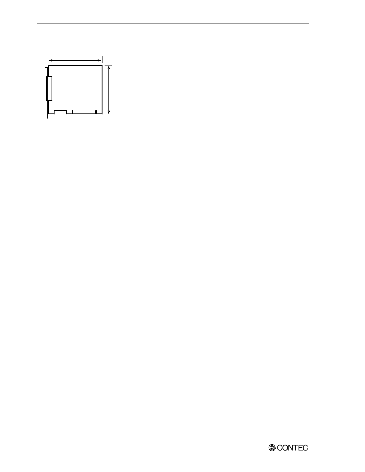
Board Dimensions [GCOM-2C2-PCI, GCOM-4C2-PCI, GCOM-8C2-PCI]
The standard outside dimension (L) is the distance
from the end of the board to the outer surface of the
slot cover.
The Board No. is described above the board.
121.69(L)
105.68(H)
[mm]
Page 52

6. About Hardware
GCOM-2C2-PCI, GCOM-4C2-PCI, GCOM-8C2-PCI
47
Page 53

GCOM-2C2-PCI
GCOM-4C2-PCI
GCOM-8C2-PCI
User’s Guide
CONTEC CO.,LTD. Aug 2006 Edition
3-9-31, Himesato, Nishiyodogawa-ku, Osaka 555-0025, Japan
Japanese http://www.contec.co.jp/
English http://www.contec.com/
Chinese http://www.contec.com.cn/
No part of this document may be copied or reproduced in any form by any means without prior written
consent of CONTEC CO., LTD. [08102006]
[0710006] Management No. A-51-215
[0710006_rev1] Parts No. LYFY741
 Loading...