

Page 1

IPC Series
FLAT PANEL DISPLAY
Aluminium-Face Type
(AC Wide,10.4"-TFT,Analog)
FPD-M21VT-AC
(AC Wide,12.1"-TFT,Analog)
FPD-L21ST-AC
(AC Wide,15.0"-TFT,Analog)
FPD-H21XT-AC
User’s Manual
CONTEC CO.,LTD.
Page 2
Check Your Package
Thank you for purchasing the CONTEC product.
The product consists of the items listed below.
Check, with the following l ist, that yo ur package is c omplete. If y ou discover dam aged or m issing item s,
contact your retailer.
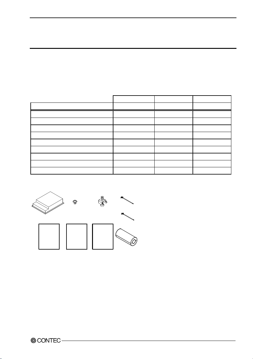
Product Configuration List
FPD-M21VT-AC FPD-L21ST-AC FPD-H21XT-AC
Name Pcs. Pcs. Pcs.
Flat panel display 1 1 1
Three-point sems screws (M3 x 6) 1 1 1
Cable fixed clamp 3 3 3
The attachment fittings 6 6 8
EU Declaration of Conformity 1 1 1
IPC Precaution List 1 1 1
Ferrite Core 1 1 3
Ferrite Core fixed clamp 0 0 2
Product guide (this sheet) 1 1 1
*1 Purchase user’s manual and individual connection cables as they are not bundled with this equipment.
For more details on the latest information of user’s manual, refer to the CONTEC’s Web site.
Three-point
Flat panel display
EU Declaratin
of Conformity
EU Declar atin
of Conformity
sems screws
(M3 x 6)
Product guide
Product guide
Ferrite Core fixed clamp
ユーザーズマニュアル
The attachment
fittings
IPC Precaution
List
IPC Precaution
List
Ferrite core
fixed clamp
Cable
fixed clamp
Ferrite Core
i
Page 3

Copyright
Copyright 2007 CONTEC CO., LTD. ALL RIGHTS RESERVED.
No part of this document may be copied or reproduced in any form by any means without prior written
consent of CONTEC CO., LTD.
CONTEC CO., LTD. makes no commitment to update or keep current the information contained in this
document.
The information in this document is subject to change without notice.
All relevant issues have been considered in the preparation of this document. Should you notice an
omission or any questionable item in this document, please feel free to notify CONTEC CO., LTD.
Regardless of the foregoing statement, CONTEC assumes no responsibility for any errors that may
appear in this document or for results obtained by the user as a result of using this product.
Trademarks
Intel and Celeron are registered trademarks of Intel Corporation. MS, Microsoft and Windows are
trademarks of Microsoft Corporati on. Ot her bra nd and pr oduct nam es are tr adem arks of t heir respe ctive
holder.
ii
ユーザーズマニュアル
Page 4

Table of Contents
Check Your Packag e............................................................................................................................i
Copyright ............................................................................................................................................ ii
Trademarks .........................................................................................................................................ii
Table of Con tents...............................................................................................................................iii
1. INTRODUCTION 1
About the P roduct............................................................................................................................... 1
Features........................................................................................................................................ 1
Customer Supp o rt ............................................................................................................................... 2
Web Site....................................................................................................................................... 2
Limited One- Ye ar Wa rr a nt y............................................................................................................... 2
How to Obtain Serv i ce ....................................................................................................................... 2
Liability............................................................................................................................................... 2
Safety Precau t io ns .............................................................................................................................. 3
Safety Infor mat i o n ....................................................................................................................... 3
Handling Pre ca u tio ns................................................................................................................... 3
2. SPECIFICATIONS 7
Function Spec if ic a ti on s ...................................................................................................................... 7
General Spec if ic at io n s........................................................................................................................ 8
Optical Displ ay S pe ci fi c at ion s ........................................................................................................... 9
3. OUTSIDE DIMENSIONS AND PART NAMES 11
Outside Dimen sio n s.......................................................................................................................... 11
Part Names........................................................................................................................................ 13
Analog RGB Con n ec to r............................................................................................................. 14
RS Touch Pane l C on ne ct o r........................................................................................................ 14
USB Touch Pan e l Co nn e c to r..................................................................................................... 15
Dip Switch ................................................................................................................................. 16
Backlight ON/ OF F Con n e cto r................................................................................................... 17
4. SETTING THE DISPLAY 19
Installation Requiremen ts................................................................................................................. 19
Panel Cut........................................................................................................................................... 20
Attaching the Fitting Used to A tta ch to th e M ain Un it.................................................................... 21
How to Mount th e Att a ch men t F itt in g s............................................................................................ 22
ユーザーズマニュアル
iii
Page 5

5. CONNECTION TO THE HOST COMPUTER 23
Analog RGB Con n ec ti on .................................................................................................................. 23
Touch Panel D at a Co m mun i ca tio n s .................................................................................................24
6. POWER SUPPLY CONNECTION 25
Power Supply Conn ec to r .................................................................................................................. 25
7. SCREEN ADJUSTMENT AND A SETUP 27
Menu Screen ..................................................................................................................................... 27
Direct Key......................................................................................................................................... 30
Memory of a Setting Value............................................................................................................... 30
8. LED INDICATORS 31
9. TOUCH PANEL 33
USB Multi-Touch Panel ................................................................................................................... 34
10. DISPLAY MODE 35
11. OPTIONS 37
iv
ユーザーズマニュアル
Page 6

1. Introduction
1. Introduction
About the Product
This product is a panel-mounted, analog RGB input type flat panel display for use with host computers such
as the CONTEC IPC series and SBCs (single board computers).
Uses a high-intensity LCD with a wide viewing field and touch panel operation via either RS-232C or
USB.
Features include an auto-scaling function and on-screen display setup screen. Front structure with
IP65-compliant ingress protection
As there is compatibility in terms of panel mounting with the existing IPC-DT/x6x series, allowing an
easy changeover of the existing system.
Features
- Standard analog RGB input for screen. RS-232C and USB interfaces for touch panel
Supports standard analog RG B input and touc h panel opera tion via eit her RS-23 2C or USB. The LCD i s
high-intensity with a wide field of view and can display either 16,777,216 colors (15 inch model) or
262,144 colors (10.4 inch and 12.1 inch models). The front on the display is made from lightweight
aluminum. The display features an analog touch panel that can emulate mouse operation via the driver
software.
- Auto-scaling feature that resizes the input screen to the LCD dot configuration
Auto-scaling feature that resizes the input screen to the LCD dot configuration
- On-screen display setup menu facilitating screen adjustment
The on-screen display setup screen can be used to set parameters such as the brightness, contrast, and
display position adjustment.
- Front structure with IP65-compliant ingress protection
Front structure with IP65-compliant ingress protection
- Panel attachment dimensions are compatible with the IPC-DT/x6x series.
The compatibility of the panel attachment fitting with the previous IPC-DT/x6x model facilitates
replacement.
- USB multiple touch panel
This function can be used in the case when t he RGB signal from the host computer is split for connecting
to multiple displays via a splitter. The function permits touch panel operation to be used at all the
displays. A maximum of eight touch panel displays can be connected.
- Input connector allows the backlight to be switched on or off externally.
The unit features an input connector that allows the backlight to be switched on or off externally.
* Fore more details on the host computer and option of this product, please contact your retailer.
ユーザーズマニュアル
1
Page 7

1. Introduction
Customer Support
CONTEC provides the following s upport services fo r you to use CONTEC products more efficiently and
comfortably.
Web Site
Japanese http://www.contec.co.jp/
English http://www.contec.com/
Chinese http://www.contec.com.cn/
Latest product information
CONTEC provides up-to-date information on products.
CONTEC also provides product manuals and various technical documents in the PDF.
Free download
You can download updated driver software a nd diff erenti al files as we ll as sample pr ograms available i n
several languages.
Note! For product information
Contact your retailer if you have any technical question about a CONTEC product or need its price,
delivery time, or estimate information.
Limited One-Year Warranty
CONTEC Products are warranted by CONTEC CO., LTD. to be free from defects in material and
workmanship for up to one year from the date of purchase by the original purchaser.
Repair will be free of char ge only w hen thi s device is ret urned fr eight pr epaid with a c opy of t he origi nal
invoice and a Return Merchandise Authorization to the distributor or the CONTEC group office, from
which it was purchased.
This warranty is not applicable for scratches or normal wear, but only for the electronic circuitry and
original products. The warranty is not applicable if the device has been tampered with or damaged
through abuse, mistreatment, neglect, or unreasonable use, or if the original invoice is not included, in
which case repairs will be considered beyond the warranty policy.
How to Obtain Service
For replacement or repair, return the device freight prepaid, with a copy of the original invoice. Please
obtain a Return Merchandise Authorization Number (RMA) from the CONTEC group office where you
purchased before returning any product.
* No product will be accepted by CONTEC group without the RMA number.
Liability
The obligation of the warrantor is solely to repair or replace the product. In no event will the warrantor
be liable for any incidental or consequential damages due to s uch defec t or consequence s that arise from
Safety Precautions. Understand the following definitions and precautions to use the product safely.
2
ユーザーズマニュアル
Page 8
1. Introduction
Safety Precautions
Understand the following definitions and precautions to use the product safely.
Safety Information
This document provides safety information u sing the foll owing sym bols to prevent a ccidents res ulting in
injury or death and the destruc tion of equi pment and res ources. Under stand the mean ings of these la bels
to operate the equipment safely.
DANGER
WAR NI NG
CAUTION
DANGER indicates an imminently hazardous situation which, if not avoided, will
result in death or serious injury.
WARNING indicates a potentially hazardous situation which, if not avoided, could
result in death or serious injury.
CAUTION indicates a potentially hazardous situation which, if not avoided, may
result in minor or moderate injury or in property damage.
Handling Precautions
CAUTION
- As this product contains precision electronic components, do not use or store in environments
subject to shock or vibration.
- This product is not intended for use in aerospace, space, nuclear power, medical equipment, or other
applications that require a very high level of reliability. Do not use the product in such applications.
- If you utilize this product in such usages where high reliability and safety are required as on the
trains, vessels, automotives or crime- or disaster-prevention devices, contact your retailer.
- Do not use or store the product in a location such as extremely high or low temperature, rapid
temperature changes, and the place which receives a strong ultraviolet ray.
Example: - Exposure to direct sun
- In the vicinity of a heat source
- Do not use or store the equipment in a dusty or humid place.
- Do not perform key operations wit h the t ouc h pane l to im plem ent a pr ocess that m ight e ndang er li fe
or result in serious damages. Design a system that can cope with incorrect key input operations.
- Do not use a sharp-edged object, such as a mechanical pencil, to operate the touch panel in order to
prevent scratching or malfunctions.
- Protect the touch panel against shock to prevent damage.
- CONTEC is not liable for a product that has been modified by the user.
- When the surface or frame of the touch panel has become dirty, wipe it with neutral detergent. Do
not wipe the touch panel with thinner, alcohol, ammonia, or a strong chlorinated solvent.
- Do not plug or unplug the connector with the equipment powered on. as doing so may result in a
malfunction or fault.
- Some products require configuration settings. Always check these requirements before use. Also,
never set switches or jumpers to other than the specified settings as this may cause a fault.
ユーザーズマニュアル
3
Page 9

1. Introduction
- A characteristic of analog to uch pan els is th a t th e detected position may vary due to changes in the
ambient environment (temperature and humidity) and changes in resistance values over time. In
such cases, the touch panel should be recalibrated and the calibration data updated.
- Regular maintenance is necessary for the backlight on the touch panel and the display for the
longevity parts.
- If you discover damaged or missing items, contact your retailer.
- The socket-outlet shall be installed near the equipment and shall be easily accessible.
- Regarding “FCC PART 15 Class A Notice”
(excluding FPD-H21XT-AC)
These product has acquired the above-mentioned
standard.
However, a sufficient margin may not be secured
for the standard. In this case, use a ferrite core
(SEIWA E04SR200935A or a compatible product)
for the AC power cable.
When attaching the f er rit e co re , co i l it nea r th e
connector while leaving it open, and then close it.
Ferrite core
Power cable
- VCCI Class A, EMC Instruction Class A Notice (only FPD-H21XT-AC)
To ensure that the FPD-H 21 XT -AC complies with the abov e stand a rd, fit th e supp lie d ferri te co res
to the AC power supply cable, RGB display cable, and RS-232C cable (or USB cable) (use the
SEIWA E04SR200935A or equivalent for the AC power cable and the SEIWA E04SR301334 or
equivalent for the RGB display cable and RS-232C cable).
When attaching the ferrite core, coil it near the connector while leaving it open, and then close it.
(When attaching the RS-232C cable (or USB cable), coil it around once near the connector while
leaving it open, and then close it.)
Ferrite core
Ferrite core
Power cable
RS-232C cable (or USB
cable)
Ferrite core
RGB display cable
Ferrite core fixed
clamp
4
ユーザーズマニュアル
Page 10

1. Introduction
Use environment
This product operates under the following operating systems:
Windows XP/2000/NT 4.0/98SE/95OSR2
* The touch panel USB interface is only supported on Windows XP/2000/98SE.
Life expectancy of components
(1) Backlight--- Display brightness decreases over time with use. The operating life of the
backlight (brightness reduced to 50% of original) is 50,000 hours for all
models. (Assuming continuous operation at 25 degrees centigrade.)
(2) Touch panel--- The operating lifetime of the touch panel is at least 1 million touches
(as tested by mechanical touching under 300g of force at a rate of two presses
per second).
(3) Power supply--- Expected life is six years for contin uous op eration at 40°C (when mounted
horizontally). However, this life may be reduced depending on the operating
temperature (in the case of higher temperatures).
* CONTEC accepts your request for replacing each consumable in the PANECON-PC as a request for
repair (at an additional cost). Contact your local retailer or CONTEC sales office.
LCD Display Pixel Drop
LCD display may have some pixels being drop ped (bright an d black spots) bel ow a certain thresh old.
Note that this is not a failure or a defect.
Burn-in on TFT Display
"Burn-in" may occur if the same display is retained for a long time. Avoid this by periodically
switching the display so that the same display is not maintained for a long time.
* Burn-In: Phenomenon characterized by a TFT display as a result of long-time display of the same
screen where a shadow-like trace persists because electric charge remains in the LCD element even
after the patterns are changed.
Connecting to a host with an existing touch panel function such as a CONTEC panel computer.
This touch panel cannot be used with a touch panel mounted in the host computer. In this case, the
touch panel function will be unavailable but screen display will still work normally.
However, on the following CONTEC panel computers, multiple touch panels can be used together
when connected via the USB interface.
- IPC-PT/6x0 Series : IPC-PT/x6x0x(PCW)x
- IPC-PT700 Series : IPC-PT700xx-xxAC
ユーザーズマニュアル
5
Page 11

1. Introduction
FCC PART 15 Class A Notice (Excluding the FPD-H21XT-AC)
NOTE
This equipment has been tested and found to comply with the limits for a Class A digital device,
pursuant to part 15 of the FCC Rules. These limits are designed to provide reasonable protection
against harmful interference when the equipment is operated in commercial environment.
This equipment generates, uses, and can radiate radio frequency energy and, if not installed and
used in accordance with the instruction manual, may cause harmful interference to radio
communications. Operation of this equipment in a residential area is likely to cause harmful
interference at his own expense.
WARNING TO USER
Change or modifications not expressly approved the manufacturer can void the user's authority to
operate this equipment.
6
ユーザーズマニュアル
Page 12
2. Specifications
2. Specifications
Function Specifications
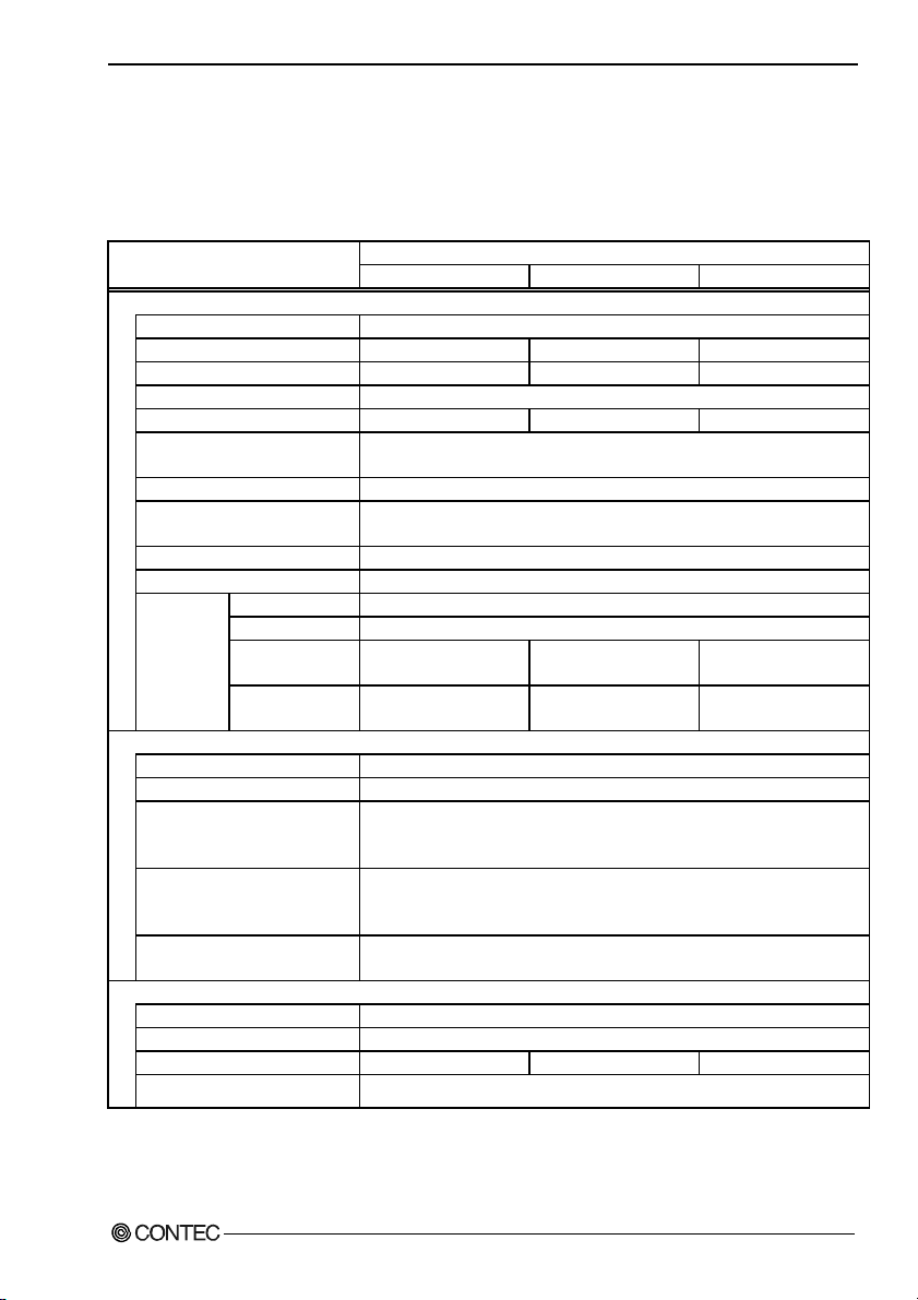
Table 2.1. Function Specifications
Item
Screen
Assembly type
Screen size
Number of pixels
Display type
Number of colors
Screen adjustment
Brightness control
Backlight control
Display interface
Cable length which recommends 5mm or less *1
Incoming
signal
specification
Touch panel
Resolution
Detection method
Touch life expectancy
Touch panel interface
Touch panel driver
(option)
Power supply input part
Power supply connector 3-pin terminal for AC power supply
Input power supply voltage
Consumption current
Consumption current
(power save mode)
*1 Using a cable longer than 5 m may reduce the image quality. The cable should be as short as possible as
degradation. in image quality may result even when the cable is 5 m or shorter depending on the type of host
computer or cable.
*2 The touch panel USB interface is only supported on Windows XP/2000/98SE.
ユーザーズマニュアル
Image signal Separate RGB, analog, positive polarity 0.7Vp-p/75Ω
Sync signal Separate V/H, TTL, positive/negative polarity
Horizontal scan
frequency
Vertical scan
frequency
FPD-M21VT-AC FPD-L21ST-AC FPD-H21XT-AC
Panel mounted
10.4 inches 12.1 inches 15 inches
640 x 480 dots
TFT Color LCD
262,144 colors 262,144 colors 16,777,216 colors
Automatic adjustment (display positioning and scaling) and manual adjustment
using the front switches
Adjustment using the front switch or software control from the host computer
Can be turned ON/OFF by front panel switch, software control from host
computer, or rear connector input.
Analog RGB input HD-SUB 15 pin (Female) connector
31 - 38kHz 31 - 48kHz 31 - 60kHz
60 - 72Hz 56 - 72Hz 56 - 75Hz
4096 x 4096
Resistive-layer analog method
One million repeated touches
(as tested by mechanical touching under 300g of force at a rate of two presses per
second)
Connect to the host computer using either USB *2 or RS-232C.
USB: USB1.1-compliant, TypeB Connector
RS-232C: 9pin D-SUB (Male) Connector
For Windows: IPC-SLIB-01
85 - 132VAC/170 - 265VAC(47 - 63Hz) Input automatic operation switch
32VA(Max.) 35VA(Max.) 40VA(Max.)
14VA (Max.)
Specification
800 x 600 dots 1024 x 768 dots
7
Page 13
2. Specifications
General Specifications
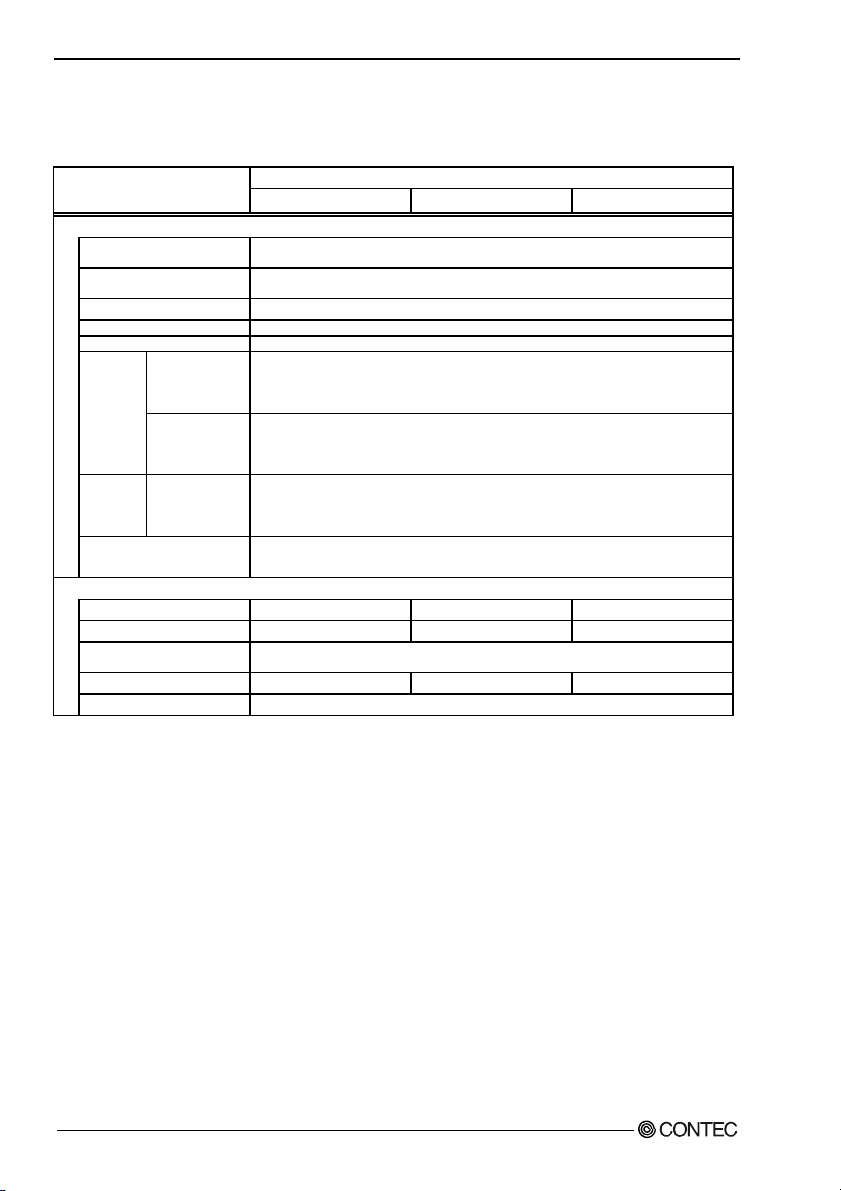
Table 2.2. General Specifications
Item
Environment
Operating
temperature
Storage
temperature
Operating humidity 10 - 90%RH (No condensation)
Floating dust Normal
Corrosive gas None
Line noise
Noise
resistance
Vibration
resistance
Shock resistance
Structure
Major dimension (mm)
Panel cut dimensions (mm)
Mountable panel
thickness
Weight
Ingress protection
Electrostatic
withstanding
voltages
Sweep
durability
FPD-M21VT-AC FPD-L21ST-AC FPD-H21XT-AC
0 - 50ºC
-10 - 60ºC
AC line: 2 kV, Signal line: 1 kV
(IEC1000-4-4Level3, EN61000-4-4Level3)
(HOST : When using the IPC-BX700-AC4)
Contact/4kV (IEC1000-4-2Level2, EN61000-4-2Level2)
Airborne/8kV (IEC1000-4-2Level3, EN61000-4-2Level3)
(HOST : When using the IPC-BX700-AC4)
10 - 57 Hz/Single-side amplitude or 0.075mm
57 - 150 Hz/1.0 G in the X/Y/Z directions for 40 minutes each
(Conforming to JIS C0040 and IEC68-2-6)
10G in the X/Y/Z directions for 11 ms; Half-sine wave
(Conforming to JIS C0041 and IEC68-2-27)
305(W) x 51.5(D) x 240(H) 316(W) x 54.5(D) x 256(H) 373(W) x 54(D) x 304(H)
292.0(W) x 227.0(H) 303.0(W) x 243.0(H) 358.0(W) x 289.0(H)
1.6mm - 7mm
3.0kg 3.2kg 4.5kg
Front part conforming to IP65
Specification
8
ユーザーズマニュアル
Page 14

2. Specifications
Optical Display Specifications
Table 2.3. Optical Display Specifications
Item Condition
Visual angle
(vertical)
Visual angle
(horizontal)
Surface
brightness
(at center)
*1 Surface brightness is a numerical value in a display simple substance.
The brightness that let the touch panel pass serves as about 77% of the above-mentioned numerical value.
Left
( φ =
-
90o )
φ=180°
φ=0°
≥10
CR
Display in white 400cd/m
o
( θ = 0
)
Display in
monochrome
φ=+90°
φ=-90°
Measurement direction
Z
θ
FPD-M21VT-AC FPD-L21ST-AC FPD-H21XT-AC
Top
o
( φ = 180
)
Specifications (25ºC Typ. Value)
50deg 50deg 50deg
70deg 70deg 70deg
70deg 70deg 70deg
70deg 70deg 70deg
2
350cd/m2 250cd/m2
X
Bottom
( φ = 0
φ
o
)
Y
Module
Right
( φ = 90
o
)
Figure 2.1. Viewing Range Definition
CAUTION
The above optical specification data shows optical characteristics of the liquid crystal in the display;
the data does not represent the actual view on the display or its viewing angles.
ユーザーズマニュアル
9
Page 15

3. Outside Dimensions and Part Names
10
ユーザーズマニュアル
Page 16

3. Outside Dimensions and Part Names
3. Outside Dimensions and Part Names
Outside Dimensions
FPD-M21VT-AC
100
75
CAUTION!
*************
******0.6N*m***
The screw bolting torque of attachment
must be 0.6N-m*MAX*.
100
MODEL :
XXXXXXXXXXXXXXXXXX
SERIAL No. : XXXXXX XXX XXXX
INPUT : XXXXXXXX XXX XXXXXXX XXXX
5 75
MADE IN ######CONTEC CO., LTD.
6
230
291
(163.4)
MENU
(216.2)
305
10
(87.7)
240
-+
Figure 3.1. Outside Dimensions of Main Unit (FPD-M21VT-AC)
FPD-L21ST-AC
CAUTION!
*************
******0.6N*m***
The screw bolting torque of attachment
12
must be 0.6N-m*MAX*.
(97.8)
(191.5)
256
MENU
-+
(252)
75
100
MODEL :
XXXXXXXXXXXXXXXXXX
SERIAL No. : XXX XXX XXX XXX X
INPUT : XXX XXX XXX XXX XX X XXX XXX X
5
CONTEC CO., LTD.
MADE IN ######
6
316
Figure 3.2. Outside Dimensions of Main Unit (FPD-L21ST-AC)
ユーザーズマニュアル
100
235.5
302
8-M4 TAP
(Maximum
tapping length : 5mm)
NL
USBSERIAL
TP I/F
CN1SW1 R GB
49
226
2-M3 TAP
(Maximum
tapping length
: 5mm)
18.5
46.5
5
[mm]
8-M4 TAP
75
(Maximum tapping
length : 5mm)
NL
USBSERIAL
TP I/F
CN1SW1 RGB
54.5
242
2-M3 TAP
(Maximum
tapping length
: 5mm)
21.5
49.5
[mm]
5
11
Page 17

3. Outside Dimensions and Part Names
FPD-H21XT-AC
100
75
CAUTION!
*************
******0.6N*m***
The screw bolting torque of attachment
15
must be 0.6N-m* MAX*.
NL
(124.85)
(236.7)
304
MENU
-+
(310)
373
8-M4 TAP
(Maximum
tapping
length
5
: 5mm)
75
100
XXXXXXXXXXXXXXXXXX
MODEL :
SERIAL No. : XXXXXXXXXXXXX
INPUT : XXXXXXXXXXXXXXXXXXXXXX
MADE IN ######
CONTEC CO ., LTD .
208
357
TP I/F
USBSERIAL
CN1SW1 RGB
68.5
288
2-M3 TAP
(Maximum tapping
length : 5mm)
21
49
[mm]
5
Figure 3.3. Outside Dimensions of Main Unit (FPD-H21XT-AC)
12
ユーザーズマニュアル
Page 18

3. Outside Dimensions and Part Names
Part Names
Screen & Touch panel
MENU
-+
BackRight side Left side
CAUTION!
*********** **
******0.6N*m***
The screw bolting torque of attachment
must b e 0. 6N-m* MAX* .
Power LED
Screen adjustment switch
NL
Power connector
XXXXXXXXXXXXXXXXXX
MODEL :
SERIAL No. : XXXXXXXXXXXXX
INPUT : XXXXXXXXXXXXXXXXXXXXX X
MADE IN ######
CONTEC CO., LTD.
Figure 3.4. Part Names
Figure 3.5. Screen Adjustment Switch
USBSERIAL
TP I/F
CN1SW1 RGB
USB touch panel connector
RS touch panel connector
Backlight ON/OFF connector
Dip switch
Analog RGB conn ector
ユーザーズマニュアル
13
Page 19

3. Outside Dimensions and Part Names
Analog RGB Connector
Table 3.1. Analog RGB Connector
Connector type 15 pin HD-SUB (FEMALE)
Pin No. Signal name Pin No. Signal name
1 RED 9 N.C.
2 GREEN 10 GND
3 BLUE 11 N.C.
4 N.C. 12 DDC DATA
5 GND 13 HSYNC
6 R-GND 14 VSYNC
7 G-GND 15 DDC CLK
8 B-GND
RS Touch Panel Connector
This connector is RS-232C compliant to be used for touch panel data communication with the host
computer.
Table 3.2. RS Touch Panel Connector
Connector type 9 pin D-SUB (MALE)
Pin No. Signal name Pin No. Signal name
1 N.C. 6 Reserved
2 TxD 7 N.C.
3 RxD 8 N.C.
4 Reserved 9 N.C.
5 GND
14
ユーザーズマニュアル
Page 20

3. Outside Dimensions and Part Names
USB Touch Panel Connector
The USB connector for communication between the host computer and touch panel.
Table 3.3. USB Touch Panel Connector
Connector type USB Type B(Receptacle)
Pin No. Signal name Pin No. Signal name
1 +5V 3 DATA+
2 DATA- 4 GND
ユーザーズマニュアル
15
Page 21

3. Outside Dimensions and Part Names
Dip Switch
A DIP switch is located on th e le ft si de of th e unit .
Switches 1 to 3 are used as the ID set ti ng w hen co nnect ing multiple touch panels via USB. See Chapte r
9 for details on connecting multiple touch panels via USB.
CAUTION
- When connecting via RS-232C or a single USB connect ion, set swit ches 1 to 3 t o OFF. (T he defa ult
factory setting)
- Ensure that the power is turned OFF before changing the DIP switch settings.
1234
ON
Figure 3.6. Dip Switch
Table 3.4. Setting a Dip Switch
No. Setting Setting description Factory setting
1 USBID0 Setting the USB touch panel ID OFF
2 USBID1 Setting the USB touch panel ID OFF
3 USBID2 Setting the USB touch panel ID OFF
4 Reserved Reserved (Leave this at OFF.) OFF
The USB ID0, 1 and 2 settings specify the ID when connecting multiple touch panels via USB.
Table 3.5. Setting a USB ID
USB ID USBID0 USBID1 USBID2
7 OFF OFF OFF
6 ON OFF OFF
5 OFF ON OFF
4 ON ON OFF
3 OFF OFF ON
2 ON OFF ON
1 OFF ON ON
0 ON ON ON
16
ユーザーズマニュアル
Page 22

3. Outside Dimensions and Part Names
Backlight ON/OFF Connector
The equipment has a backlight ON/OFF connector on the back. Given below are the pin assignment of
the connector and its applicable example.
Table 3.6. Remote Co n tro l Cabl e Con n ect or
Connector type S2B-XH-A (mfd. by JST)
Pin 1 - 2 Function
Open Backlight ON
Short Backlight OFF
Connector Applicable Example
Switch
1
2
Figure 3.7. Connector Applicable Example
CAUTION
- Backlight ON/OFF cable is not bundled with this product; it must be prepared by the user.
- Backlight ON/OFF control can be implemented by means of software from the host computer.
However, please do not use software control from the host computer when using this connector to
control the backlight.
Applicable connector type
Housing : XHP-2 (mfd. by JST)
Contact (two pieces used) : SXH-001T-P0.6 (mfd. by JST)
ユーザーズマニュアル
17
Page 23

3. Outside Dimensions and Part Names
18
ユーザーズマニュアル
Page 24

4. Setting the Display
4. Setting the Display
Installation Requirements
Please mount the display with an upright orientation.
To maintain the ambient temperature within the installation environment requirement range, provide a
gap of 30mm or more between the main unit and any adjacent equipment.
Side view
Panel
30mm or more(above)
30mm or more
(Bottom)
Botton view
30mm or more (Side)
CAUTION!
Don't connect 1 and 2 of
12VDC-IN simultaneously.
12VDC-IN*1*2***
************
Interface surface
Panel
30mm or more (back)
Figure 4.1. Distances between the FPD and Its Vicinity
ユーザーズマニュアル
19
Page 25

4. Setting the Display
Panel Cut
Cut the display mount panel in the following dimensions. The four corners of the solid-line rectangle
define the panel cut dimensions.
+1
292
-0
R1 or less
+1
-0
227
Panel thickness range: 1.6 to 7mm
[mm]
Figure 4.2. FPD-M21VT-AC [10.4inch] Panel Cut Dimensions
+1
303
-0
R1 or less
+1
-0
243
Panel thickness range: 1.6 to 7mm
[mm]
Figure 4.3. FPD-L21ST-AC [12.1inch] Panel Cut Dimensions and Stud Hole Positions
+1
358
-0
R1 or less
+1
-0
289
Panel thickness range: 1.6 to 7mm
[mm]
Figure 4.4. FPD-H21XT-AC [15inch] Panel Cut Dimensions and Stud Hole Positions
20
ユーザーズマニュアル
Page 26

4. Setting the Display
Attaching the Fitting Used to Attach to the Main Unit
(1) Hold the main uni t f ro m the ou ts ide of th e pa nel .
Figure 4.5. Attaching the Fitting Used to Attach to the Main Unit < 1 / 2 >
(2) Hold the attach from the inside of the panel.
Metal fittings
Panel
Main body
Overtightening screws may result in damage.
Figure 4.5. Attaching the Fitting Used to Attach to the Main Unit < 2 / 2 >
ユーザーズマニュアル
21
Page 27

4. Setting the Display
How to Mount the Attachment Fittings
The “Cable fixed clamp” is bundled with this product.
The system unit has three holes for accepting cable ties. Using a cable clamp for a cable with lock-less
connector, such as the USB cable, prevents the connector from being unplugged.
Use the cable ties and cable clamps appropriately according to the connecting states and wiring
directions of cables.
The photo below shows an example of using a cable clam p. Fix t he cable with a clam p without applyi ng
stress to the connector.
22
ユーザーズマニュアル
Page 28

5. Connection to the Host Computer
5. Connection to the Host Computer
Purchase individual connection cables as they are not bundled with this equip ment.
Analog RGB Connection
This connection inputs analog RGB display signals to the equipment. Connect the cable to the analog
RGB connector on the host computer.
Table 5.1. Recommendation Display Cable
Model Maker Cable length
KC-V2
KC-V5
If you use any other cable, select a shielded cable the wire carrying the RGB and H/Vsync si gnals and the
grounded wire in a twisted pair. Note that a non-twisted-pair cable may degrade image quality, in
particular, which is longer than 2 m.
SANWA SUPPLY INC.
SANWA SUPPLY INC.
2m
5m
ユーザーズマニュアル
23
Page 29

5. Connection to the Host Computer
Touch Panel Data Communications
These connections are used to send touch panel data to the host comput er via the USB or RS- 232C serial
port. Connect to the USB port or serial port (COM port) on the host computer.
Table 5.2. Example of a USB connection cable (USB Type A(Host) ⇔ Type B(Display)cable)
Model Maker Cable length
KU20-2H
KU20-5H
SANWA SUPPLY INC.
SANWA SUPPLY INC.
Table 5.3. RS-232C Option Cable (RS-232C Straight Cable)
Model Maker Cable length
IPC-CBL3-2
IPC-CBL3-5
CONTEC
CONTEC
CAUTION
- Touch panel driver software is required to use the touch panel. Purchase optional driver software
[IPC-SLIB-01 for windows] or download one from the CONTEC’s web site
(http://www.contec.co.jp/download/).
- Please use the driver for "IPC-DT/M20V(PC)T, IPC-DT/L20S(PC)T, IPC-DT/H20X(PC)T" when
using it with V1.49 or less of IPC-SLIB-01. Moreover, please use it with V1.20 or more of
IPC-SLIB-01 when you use the touch panel driver software for USB.
- The USB connection can only be used on Windows XP, 2000, or 98SE. Connect via the RS-232C
interface if using a different OS.
- Use either USB or RS-232C for connecting the touch panel. The touch panel cannot be connected
via both interfaces at the same time.
- When using the USB connection, the screen image may disappear momentarily when the US B cable
is connected or disconnected and when the computer power is turned ON or OFF.
- When using the USB connection via a hub, the unit may not operate correctly in some cases
depending on the other USB devices connected to the hub. Please check the operation before using
in practice.
2m
5m
2m
5m
24
ユーザーズマニュアル
Page 30

6. Power Supply Connection
6. Power Supply Connection
This product operates from an AC power supply. The unit includes a terminal block for connecting the
power supply.
Please connect a black line of the AC power cable with L, connect the white line in N similarly, and
connect a green line with FG.
Power Supply Connector
Table 6.1. Power Supply Connector
Connector
type
AC input terminal
23
1
- Screw diameter : M3.5, Pitch between pins : 9.5mm
- Applicable pin
7.8
L
N
Pin No. Signal name
1 FG(Frame Gnd)
2 N
3 L
(Notes) This product has no AC power ON/OFF switch.
3.9
6.2
[mm]
ユーザーズマニュアル
25
Page 31

6. Power Supply Connection
26
ユーザーズマニュアル
Page 32

7. Screen Adjustment and a Setup
7. Screen Adjustment and a Setup
The equipment has screen adjustment switches [MENU], [+], and [-]. Use these switches to adjust the
screen. (For the locations of the switches, see “Outside Dimensions and Part Names” in Chapter 3.)
When using the equipment for the first time or after changing the output screen mode of the host
computer, execute AUTO ADJUST first on the menu screen. Use these switches also to adjust the
screen brightness and contrast and to make settings for the touch panel.
Menu Screen
Pressing the [MENU] switch displays the main menu screen. Use the [+] and [-] switches to select
individual items, adjust them, then press the [MENU] to save the settings.
Figure 7.1. Main Menu Screen
: Adjust this item when the screen is partly blurred or flickering. Press [+] or [-]
PHASE
AUTO ADJUST :
CAUTION
AUTO ADJUST may fail to adjust the screen correctly depending on the host co mputer or the
display screen (mostly black screen such as in the DOS text mode). In such a case, adjust
POSITION and WIDTH to manually optimize the screen.
ユーザーズマニュアル
while checking the screen to optimize the item.
Select AUTO ADJUST when using the equipment for the first time or when the
screen cannot be displayed normally due to a change made to the display mode.
Select this item and press [MENU] to accept your selection, and the equipment
starts performing automatic adjustment.
27
Page 33

7. Screen Adjustment and a Setup
POSITION :
Figure 7.2. POSITION Submenu
H-POSITION : Select this item to adjust the horizontal position of the screen. Press [+] or [-]
V-POSITION : Select this item to adjust the vertical position of the screen. Press [+] or [-] while
MAIN MENU : Select this item to return to the main menu.
SCREEN :
Even when AUTO ADJUST fails to position the screen correctly, you can adjust
the horizontal and vertical positions of the display screen. Select this item to
invoke the submenu, select a desired item using [+] or [-], then press [MENU] to
accept the setting made.
while checking the screen to optimize the item.
checking the screen to optimize the item.
Se lect this item to adjus t the display status of the screen. Select this item to invoke
the submenu, select a desired item using [+] or [-], then press [MENU] to accept
the setting made.
Figure 7.3. SCREEN Submenu
CONTRAST : Select this item to a djust t he contra st of the s cree n. Pres s [+] or [-] to optim ize t he
BRIGHTNESS : Select this item to adjust the brightness of the backlight. Press [+] or [-] to
SYNC RANGE : The detection accuracy of Synchronous Idle is adjusted. Please adjust a set value
MAIN MENU : Select this item to return to the main menu.
28
item.
optimize the item. The brightness can also be adjusted by pressing the [+] and [-]
keys without the MENU screen displayed, as the direct brightness control keys.
when the screen changes frequently, and it doesn't display it normally though
Synchronous Idle changed. Press [+] or [-] to optimize the item. ( The default value
is 20.)
ユーザーズマニュアル
Page 34

7. Screen Adjustment and a Setup
WIDTH :
TOUCHPANEL :
Figure 7.4. TOUCHPANEL Submenu
TOUCHPANEL MODE :
ON OFF : Select this item to turn ON (enable) or OFF (disable) the touch panel operation.
Usually, this item does not have to be set as the touch panel i s turned ON (enable d)
INTERVAL : Select this item to adjust the scan timing of the touch panel. Press [+] or [-] to
BEEP : Select this item to turn on or off the click tone of the touch panel. (Factory
ON/OFF setting on the touch pa nel dri ver (host s ide) is als o available. See also the
MAIN MENU : Select this item to return to the main menu.
INITIALIZATION :
When vertical stripes have gone out to the screen, it adjusts it. Press [+] or [-] while
checking the screen to optimize the item.
Select this item to adjust the status of the touch panel. Select this item to invoke
the submenu, select a desired item using [+] or [-], then press [MENU] to accept
the setting made.
Select the touch panel mode (WINDOWS or DOS) depending on the host OS.
(Factory setting:WINDOWS)
(The equipment is st art ed alw ays wi th th is i te m se t to O FF.)
automatically upon startup of the touch pa nel driver. Note, however, t hat the touc h
panel does not work when the equipment is connected to the host with the touch
panel driver already up and running or when the power to the equipment is
recycled. In such cases, set this item to ON (enabled).
increase or decrease the response of the touch panel. (Factory setting:10)
setting:OFF)
driver setting when you change the setting.
Select this item to reset all items to the factory defaults If the screen has become
blank or displayed abnormally, use this item to initialize the equipment. The
initialization is executed by selecting “YES” and pressing [MENU]. It can al so be
executed by turning on the equipment w hile hold ing d ow n the [ME NU] key as t he
direct initialization key.
ユーザーズマニュアル
29
Page 35

7. Screen Adjustment and a Setup
Direct Key
BRIGHTNESS : The brightness of the backlight can be adjusted by pressing the [+] and [-] keys
INITIALIZATION : All the settings can be reset to the factory defaults by turning on the equipm ent
Power save mode : You can place the equipment in the power save mode by depr essing both of th e
* Recycling the power to the equipment in the power save mode recovers it to the normal display sta te.
* The POWER LED on the front face remains blinking in green in the power save mode.
without the menu screen displayed.
while holding down the [ME NU ] ke y.
[+] and [-] keys at the same time without the menu screen displayed. This can
force the screen display and backlight to be turned off.
Release the buttons when “!POWERSAVE MODE” appears on the screen.
You can recover the screen from the power save mode by pressing any of the
front switches. The power consumption of the equipment in the power save
mode is about 1/5 of that during normal operation. Turning off the backlight
when not required the backlight to extend its life.
Memory of a Setting Value
The equipment retains its settings even when the power is turned off.
Note, however, that the following settings are reset to their defaults without being retained.
- The power save mode setting made by the direct key is reset to the normal state when the power is
turned on.
- The TOUCH PANEL ON/OFF setting is set to OFF when the power is turned on.
30
ユーザーズマニュアル
Page 36

8. LED Indicators
8. LED Indicators
The POWER LED on the front face indicates each state of the display as follows:
Table 8.1. LED Indicators
LED status Description
OFF The power supply off or the equipment not started normally
Green(ON) Normal operation
Green(Flashing) Power save mode
Orange(Flashing) Unsupported signal input *1
Orange(Flashing) No signal input *2
*1 The LED looks like this when the equipment cannot process the input
signal to provide normal display, for example, when the horizontal/vertical
sync signal frequency is exceeding the supported frequency. See Chapter
10 "Display mode" for the display modes supported by this equipment.
*2 The LED looks like this also when the horizontal or vertical sync signal is
turned off by the power management function of the host computer. The
equipment enters the power save mode automatically when no signal has
been input for about two seconds.
ユーザーズマニュアル
31
Page 37

8. LED Indicators
32
ユーザーズマニュアル
Page 38

9. Touch Panel
9. Touch Panel
This equipment has a touch panel that enables keyboard-less, mouse-less operations by communication
with the host computer using the RS-232C cable.
Touch panel
-+
MENU
Tou ch p ane lHost PC Touch panel controller
CPU
Communication
c
ontroller
CPU
INT
Serial
communication
Figure 9.1. Touch Panel and Block Diagram
Data input at the touch panel is processed by the tou ch panel contr oller and pa ssed to the host PC via the
serial port on the CPU in the controller.
Before the touch panel can be used, touch panel driver software must be installed. Note that the driver
software is not bundled with this product. Purchase the one separately or download it from the
CONTEC’s web site.
For further details, refer to the READ_ME file for each driver.
< Option touch panel driver >
Windows XP/2000/NT 4.0/98SE/95OSR2 : IPC-SLIB-01
CAUTION
- The USB touch panel driver software requires V1.20 or later of IPC-SLIB-01.
- The USB connection can only be used on Windows XP, 2000, or 98SE. Connect via the RS-232C
interface if using a different OS.
- Use either USB or RS-232C for connecting the touch panel. The touch panel cannot be connected
via both interfaces at the same time.
- When using the USB connection, the screen image may disappear momentarily when the US B cable
is connected or disconnected and when the computer power is turned ON or OFF.
ユーザーズマニュアル
33
Page 39

9. Touch Panel
USB Multi-Touch Panel
This function can be used in the case when t he RGB signal from the host computer is split for connecting
to multiple displays via a splitter. The function permits touch panel operation to be used at all the
displays. A maximum of eight touch panel displays can be connected.
Note that all touch panels must be connected via USB and, to allow the touch panel driver software on
the host computer to identify each device, a different USB ID must be set on the DIP switch located on
the side of each display unit.
USB ID7
RGBdistributor RGBcable
8sets(Max.)
USB ID0
USB HUBHost PC USB cable
Tou ch p an el d isp la y
Figure 9.2. Example of connection of a USB multi-touch panel
You can use a CONTEC IPC-PT/600 series panel computer as the host PC.
In this case, the ID of the touch panel in the panel computer is fixed at ID7. Set the IDs of the external
displays in the range
USB ID0 - USB ID6 (a maximum of seven external displays can be connected).
CAUTION
You cannot use multiple touch panels via the RS-232C interface.
34
ユーザーズマニュアル
Page 40

10. Display Mode
V
V
V
10. Display Mode
This equipment supports the following display modes:
Table 10.1. FPD-M21VT-AC
Video mode Number of
pixels (dot)
VGA 640 x 350 25.18 31.47 70 *1, *2
VGA 640 x 400 25.18 31.47 70
VGA 640 x 480 25.18 31.47 60
VESA 640 x 480 31.50 37.86 72
*1 The vertical display size does not reach the full-screen display size.
*2 Since the aspect ratio is not 4:3, the screen display is extended vertically.
Table 10.2. FPD-L21ST-AC
Video mode Number of
pixels (dot)
VGA 640 x 350 25.18 31.47 70 *1, *2
VGA 640 x 400 25.18 31.47 70
VGA 720 x 400 28.32 31.47 70 *2
VGA 640 x 480 25.18 31.47 60
VESA 640 x 480 31.50 37.86 72
VESA 800 x 600 36.00 35.16 56
VESA 800 x 600 40.00 37.88 60
VESA 800 x 600 50.00 48.08 72
*1 The vertical display size does not reach the full-screen display size.
*2 Since the aspect ratio is not 4:3, the screen display is extended vertically.
Dot clock (MHz) Horizontal
frequency (kHz)
Dot clock (MHz) Horizontal
frequency (kHz)
ertical frequency
(Hz)
ertical frequency
(Hz)
Table 10.3. FPD-H21XT-AC
Video mode Number of
VGA 640 x 350 25.18 31.47 70 *1, *2
VGA 640 x 400 25.18 31.47 70
VGA 720 x 400 28.32 31.47 70 *2
VGA 640 x 480 25.18 31.47 60
VESA 640 x 480 31.50 37.86 72
VESA 640 x 480 31.50 37.50 75
VESA 800 x 600 36.00 35.16 56
VESA 800 x 600 40.00 37.88 60
VESA 800 x 600 50.00 48.08 72
VESA 800 x 600 49.50 46.88 75
VESA 1024 x 768 65.00 48.36 60
VESA 1024 x 768 75.00 56.48 70
VESA 1024 x 768 78.75 60.02 75
*1 The vertical display size does not reach the full-screen display size.
*2 Since the aspect ratio is not 4:3, the screen display is extended vertically.
pixels (dot)
ユーザーズマニュアル
Dot clock (MHz) Horizontal
frequency (kHz)
ertical frequency
(Hz)
35
Page 41

10. Display Mode
CAUTION
- The number of display pixels of the LCD is 640 x 480 d ots o n the FPD-M 21VT-A C, 800 x 600 dots
on the FPD-L21ST-AC, and 1024 x 768 dots on th e FPD-H21 XT-AC . When the input has a
resolution lower than the number of display pixels of each model, the screen display is enlarged
automatically. Note, in this case, that the display quality is therefore degraded in clearness
compared to the screen displayed at the resolution that matches the number of display pixels of the
LCD.
- The equipment cannot provide normal display at a resolution or frequency other than the supported
display modes.
- The Windows full-screen MS-DOS window may not display correctly in some cases depending on
the connected host computer.
36
ユーザーズマニュアル
Page 42

11. Options
11. Options
Double-sided screen protective sheets
- IPC-CV : 10-inch [IPC-DT/M20V(PC)T] screen protective sheets (10 sheets)
- IPC-CV12 : 12.1-inch [IPC-DT/L20S(PC)T] screen protective sheets (10 sheets)
- IPC-CV15 : 15-inch [IPC-DT/H21X(PC)T] screen protective sheets (10 sheets)
Optional cables
- IPC-ACCODE3 : AC power cable (For 2m 125VAC)
- IPC-CBL3-2 : RS-232C cable for touch panels (2m)
- IPC-CBL3-5 : RS-232C cable for touch panels (5m)
Driver
- IPC-SLIB-01 : Driver & Utility Soft Set(CD-ROM version)
Recommendation Cable (Maker: SANWA SUPPLY INC.)
- KC-V2 : RGB display cable (2m)
- KC-V5 : RGB display cable (5m)
- KU20-2H : USB cable for touch panel (2m)
- KU20-5H : USB cable for touch panel (5m)
Manual
- FPD-21-HMJ : User’s manual (Japanese) for FPD-M21VT-AC, FPD-L21ST-AC,
FPD-H21XT-AC series
- FPD-21-HMU : User’s manual (English) for FPD-M21VT-AC, FPD-L21ST-AC,
FPD-H21XT-AC series
ユーザーズマニュアル
37
Page 43

FPD-M21VT-AC
FPD-L21ST-AC
FPD-H21XT-AC
User’s Manual
IPC-DT/20-HMU
CONTEC CO.,LTD. December 2007 Edition
3-9-31, Himesato, Nishiyodogawa-ku, Osaka 555-0025, Japan
Japanese http://www.contec.co.jp/
English http://www.contec.com/
Chinese http://www.contec.com.cn/
No part of this document may be copied or reproduced in any form by any means without prior written
consent of CONTEC CO., LTD. [12212007]
[12212007] Management No. A-51-517
Parts No. LYHX361
 Loading...