

Page 1

FlexNetViewer
FlexNetViewer HD
Video Transmitter Over Ethernet
RP-VL-S-02
Video Receiver Over Ethernet
RP-VL-R-02
User’s Guide
CONTEC CO.,LTD.
Page 2

Check Your Package
Thank you for purchasing this CONTEC product.
The product package contains the items listed below.
Check the contents of the product package. If you discover any damaged or missing items, contact the
distributor.
Contents
- Unit (One of RP-VL-S-02, RP-VL-R-02) …1 - First step guide …1
- AC adapter …1 - AC cable *1 ...1
- Rubber feet ...4 - DC plug attachment …1
- Cable tie [RP-VL-S-02 only] …1 - M3 screw …1
- Ferrite core [RP-VL-S-02 only]…1 - Warranty Certificate…1
- Serial number label…1
*1 Use the AC cable conformed to your area standards.
CAUTION
The main unit management utility to remotely (via LAN) perform settings for this products (IP
addresses, etc.) can be downloaded (free of charge) from our website. The image transfer utility
software to make your computer a transmitter or receiver is sold separately.
RP-VL-S-02, RP-VL-R-02
i
Page 3

Copyright
Copyright 2010 CONTEC CO., LTD. ALL RIGHTS RESERVED.
No part of this document may be copied or reproduced in any form by any means without prior written
consent of CONTEC CO., LTD.
CONTEC CO., LTD. makes no commitment to update or keep current the information contained in this
document. The information in this document is subject to change without notice.
All relevant issues have been considered in the preparation of this document. Should you notice an
omission or any questionable item in this document, please feel free to notify CONTEC CO., LTD.
Regardless of the foregoing statement, CONTEC assumes no responsibility for any errors that may
appear in this document or for results obtained by the user as a result of using this product.
Trademarks
MS, Microsoft and Windows are trademarks of Microsoft Corporation. Other brand and product names
are trademarks of their respective holder.
RP-VL-S-02, RP-VL-R-02
ii
Page 4

Table of Contents
Check Your P ackage................................................................................................................................ i
Copyright .................................................................................................................................................ii
Trademarks ..............................................................................................................................................ii
Table of Contents ...................................................................................................................................iii
1 BEFORE USING THE PRODUCT 1
About the P r o duct ...................................................................................................................................1
Features............................................................................................................................................. 1
Support Software.............................................................................................................................. 3
Adapter (Option)..............................................................................................................................3
Customer Su pport.................................................................................................................................... 4
Web Site ........................................................................................................................................... 4
Limited On e-Year Warranty................................................................................................................... 4
How to Obta in Service............................................................................................................................ 4
Liability ................................................................................................................................................... 4
Safety Precautions................................................................................................................................... 5
Safety Information ...........................................................................................................................5
Handling Precautions....................................................................................................................... 5
Environment..................................................................................................................................... 7
Inspection .........................................................................................................................................7
Storage.............................................................................................................................................. 7
Disposal ............................................................................................................................................7
2 SETUP 9
Setting the Hardware...............................................................................................................................9
Parts of this Product an d Factory De faults...................................................................................... 9
Setting the Group ID...................................................................................................................... 11
Setting the Maintenanc e SW ......................................................................................................... 12
LED ................................................................................................................................................13
Checking the IP Address................................................................................................................14
Settings Using the Software.................................................................................................................. 14
Setup Method ........................................................................................................................................ 15
Table Top Installation ....................................................................................................................15
Mounting th e Product on the Monitor........................................................................................... 15
Cable Tie Attachment Method ......................................................................................................15
How to mount the DC plug attachment.........................................................................................16
Startup and Stop ....................................................................................................................................17
Startup pro cedure ...........................................................................................................................17
Stop procedure ...............................................................................................................................18
RP-VL-S-02, RP-VL-R-02
iii
Page 5

3 FUNCTION 19
Video Transfer Functio n .......................................................................................................................19
Example of connection w ith a PC..................................................................................................19
Example of connection w ith a camera...........................................................................................20
Remote seri al I/O function ....................................................................................................................21
Image transfer utility (option) ...............................................................................................................22
Controllin g display sc r eens in remote locations by Window s PCs..............................................22
Monitoring computer d i splay screen s in remote l ocations ........................................................... 22
4 ABOUT HARDWARE 23
Hardware sp e cification..........................................................................................................................23
Physical dimensions ..............................................................................................................................26
Interface Connector ...............................................................................................................................28
Image inpu t, Image outp ut: Pin assignment of DV I -D IN, DVI-D O UT.....................................28
Image inpu t: Pin assignment of VIDEO IN...................................................................................29
Remote seri al I/O: Pin a ssignment o f SIO.....................................................................................29
LAN: Pin assignment of LAN connec tor ......................................................................................30
DC Jack: Pin assignment o f 5V DC-IN.........................................................................................31
RP-VL-S-02, RP-VL-R-02
iv
Page 6

1. Before Using the Product
1 Before Using the Product
This chapter provides information you should know before using the product.
About the Product
The FlexNetViewer HD is a video communications unit allowing long distance transmission via LAN of
high-definition images.
It can act as a digital signage system, remote viewing system or live image transmission system with
high picture quality for a variety of sectors, examples being public facilities, transportation, shopping
malls, mass retailing stores and amusement facilities.
The FlwxNetViewer HD supports DVI signals that are compatible with digital signals with a resolution
up to 1920 x 1080, and it also supports composite signals that are compatible with analog video
equipment, so it can be directly connected to video camera operating.
RP-VL-S-02 is a transmitter that converts input image signals into LAN packet signals and then sends
them.
RP-VL-R-02 is a receiver that converts received LAN packet into image signals and then outputs the
signals.
When you use the transmitter and receiver as a set, you can connect monitors in a 1:1 or 1:N
configuration without depending on the platform such as a PC and OS.
Using the optional image transfer utility allows a variety of connections with the PC acting as a
transmitter or receiver.
In addition, the RP-VL-R-02 can also use the serial I/O (RS-232C) by utilizing the virtual COM driver
produced by CONTEC.
Features
- Monitor screen capability can be extended by LAN.
PCs and monitors with limited cable length can easily be extended through the use of commercially
available LAN cables (category 5 or higher) or hubs between the transmitter and receiver. Image
signals are converted to LAN packets, making possible transmission with minimal loss of picture
quality due to distance.
- Screen display does not depend on the PC or OS.
When you use the transmitter (RP-VL-S-02) and receiver (RP-VL-R-02) as a set, you can display screen
images without depending on your platform such as a PC and OS. You can send the same screen
images to monitors in a 1:1 or 1:N configuration. No complicated utility setup is required.
- Compatibility with high-definition video
High-definition video communication is made possible by the on-board picture compression CPU.
- Simple transmission of live images
The on-board composite input terminal (for the transmitter) allows direct connection to video cameras
and simple real-time transmission of live images.
RP-VL-S-02, RP-VL-R-02
1
Page 7

1. Before Using the Product
- Multi-monitor configuration is possible.
Connecting multiple receivers (RP-VL-R-02) allows you to send the image shown on the transmitter
monitor screen onto multiple monitors simultaneously. This option requires the same number of
receivers (RP-VL-R-02) as the monitors.
- COM port as standard setup
The receiver (RP-VL-R-02) has a COM port as part of its standard setup. By installing the appropriate
driver on the transmitting Windows PC, it can be allocated for use as a COM port on the PC itself,
allowing remote control of serial communications equipment via LAN.
- Image transfer utility and main unit management utility are available.
When the image transfer utility (option) is installed on a PC, it can be used just like a transmitter or
receiver. A PC can be connected as a transmitter to multiple receivers (RP-VL-R-02) or as a receiver
to multiple transmitters (RP-VL-S-02).
Also, when the main unit management utility (*1) is used, various settings can be performed for the
transmitter (RP-VL-S-02) and the receiver (RP-VL-R-02) via Ethernet.
*1 The main management utility can be downloaded from our website (free of charge).
- Fittings for monitor attachment optionally available
Fittings to attach this product to the back of monitors are optionally available. The fittings are
compliant with the VESA standards (75mm x 75mm or 100mm x 100mm).
CAUTION
- Transmitters and receivers may cause an image distortion or fail to transfer images due to the
compatibility with the PC or monitor to be connected. When using this product ensure to utilize
equipment on loan from CONTEC to make an evaluation in the actual user environment.
- A connection beyond the router (Internet connection, for example) is an one-to-one connection.
Please be careful as it requires advanced knowledge on network, such as obtaining a global IP
address.
- Use a cross cable for directly connecting the transmitter and receiver via LAN cable.
RP-VL-S-02, RP-VL-R-02
2
Page 8

1. Before Using the Product
Support Software
You should use CONTEC support software according to your purpose and development environment.
Main unit management utility FNVHD-UTM
(Downloadable from the CONTEC’s Web site, free of charge)
This utility can be used to set the IP ad dresses of the transmitter (RP-VL-S-02) and the receiver (RP-VL-R-02), the
availability of the remote serial I/O (SIO) as well as communication specifications.
Refer to the document file of the main management utility in regards to detailed information on compatible operating
systems and so on.
URL: http://www.contec.com
Image transfer utility RP-VL-UTIL-V1 (option)
Once you install this utility on your PC, you can connect the PC directly to either the transmitter (RP-VL-S-02) or the
receiver (RP-VL-R-02) to dis play screen images.
The utility allows you to display screen images from one PC monitor onto multiple monitors or display screen images
from multiple PC monitors onto one split screen monitor.
The trial version can be downloaded from
image transfer
the
utility in regards to detailed information on compatible operating s ystems and so on.
the CONTEC’s Web site
(free of charge). Refer to the document file of
Adapter (Option)
VESA Bracket for Flex Net Viewer HD (100mm x 100mm) : BRK-VL02-100
VESA Bracket for Flex Net Viewer HD (75mm x 75mm) : BRK-VL02-75
DVI-D Cable(2m) : IPC-DVI/D-020
DVI-D Cable(5m) : IPC-DVI/D-050
* Check the CONTEC’s Web site for more information on these options.
RP-VL-S-02, RP-VL-R-02
3
Page 9

1. Before Using the Product
Customer Support
CONTEC provides the following support services for you to use CONTEC products more efficiently
and comfortably.
Web Site
Japanese http://www.contec.co.jp/
English http://www.contec.com/
Chinese http://www.contec.com.cn/
Latest product information
CONTEC provides up-to-date information on products.
CONTEC also provides product manuals and various technical documents in the PDF.
Free download
You can download updated driver software and differential files as well as sample programs available in
several languages.
For product information
Contact your retailer if you have any technical question about a CONTEC product or need its price,
delivery time, or estimate information.
Limited One-Year Warranty
CONTEC products are warranted by CONTEC CO., LTD. to be free from defects in material and
workmanship for up to One year from the date of purchase by the original purchaser.
Repair will be free of charge only when this device is returned freight prepaid with a copy of the
original invoice and a Return Merchandise Authorization to the distributor or the CONTEC group office,
from which it was purchased.
This warranty is not applicable for scratches or normal wear, but only for the electronic circuitry and
original products. The warranty is not applicable if the device has been tampered with or damaged
through abuse, mistreatment, neglect, or unreasonable use, or if the original invoice is not included, in
which case repairs will be considered beyond the warranty policy.
How to Obtain Service
For replacement or repair, return the device freight prepaid, with a copy of the original invoice. Please
obtain a Return Merchandise Authorization number (RMA) from the CONTEC group office where you
purchased before returning any product.
* No product will be accepted by CONTEC group without the RMA number.
Liability
The obligation of the warrantor is solely to repair or replace the product. In no event will the
warrantor be liable for any incidental or consequential damages due to such defect or consequences that
arise from inexperienced usage, misuse, or malfunction of this device.
RP-VL-S-02, RP-VL-R-02
4
Page 10

1. Before Using the Product
Safety Precautions
Review the following definitions and precautions to use the product safely.
Safety Information
This document provides safety information using the following symbols to prevent accidents resulting
in injury or death and the destruction of equipment and resources. Review the meanings of these labels
to operate the equipment safely.
DANGER
WAR NI NG
CAUTION
Handling Precautions
DANGER
Do not use the product where it is exposed to flammable or corrosive gas. Doing so may result in
an explosion, fire, electric shock, or failure.
CAUTION
- Do not use or store the product in a location exposed to extremely high or low temperature or
susceptible to rapid temperature changes.
Example: - Exposure to direct sunlight
- In the vicinity of a heat source
- Do not use the product in extremely humid or dusty locations. It is extremely dangerous to use the
product with its interior penetrated by water or any other fluid or conductive dust. If the product
must be used in such an environment, install it on a dust-proof control panel, for example.
- Avoid using or storing the device in locations subject to shock or vibration.
- Do not use or store the product in the vicinity of devices that generate strong magnetic force or
electric wave.
- Do not use or store the product in the presence of chemicals.
- Be sure to unplug the power cable from a wall outlet before plugging or unplugging a cable or any
connector.
- Do not modify this product. CONTEC will bear no responsibility for any problems, etc., resulting
from modifying this product.
- In the event of failure or abnormality (foul smells or excessive heat generation), unplug the power
cord immediately and contact your retailer.
- To clean this product, wipe it gently with a soft cloth dampened with either water or mild detergent.
Do not use chemicals or a volatile solvent, such as benzene or thinner, to prevent pealing or
discoloration of the paint.
DANGER indicates an imminently hazardous situation which, if not avoided, will
result in death or serious injury.
WARNING indicates a potentially hazardous situation which, if not avoided, could
result in death or serious injury.
CAUTION indicates a potentially hazardous situation which, if not avoided, may
result in minor or moderate injury or in property damage.
RP-VL-S-02, RP-VL-R-02
5
Page 11

1. Before Using the Product
- VCCI class A, FCC PART15 Class A, CE EMC Directive Class A addenda
This product complies with VCCI Class A, FCC PART15 Class A, and CE EMC Directive Class A
when used under the following conditions with video camera input.
- Attach the ferrite core provided to the video cable.
- Ground the FG terminal.
Diagram showing the ferrite core attached to the cable.
Attach near the Video In connector of the product and turn the cable twice (wind it once).
FCC PART 15 Class A Notice
NOTE
This equipment has been tested and found to comply with the limits for a Class A digital device,
pursuant to part 15 of the FCC Rules. These limits are designed to provide reasonable protection
against harmful interference when the equipment is operated in commercial environment.
This equipment generates, uses, and can radiate radio frequency energy and, if not installed and
used in accordance with the instruction manual, may cause harmful interference to radio
communications. Operation of this equipment in a residential area is likely to cause harmful
interference at his own expense.
WARNING TO USER
Change or modifications not expressly approved the manufacturer can void the user's authority to
operate this equipment.
RP-VL-S-02, RP-VL-R-02
6
Page 12

1. Before Using the Product
Environment
Use this product in the following environment. If used in an unauthorized environment, the unite may
overheat, malfunction, or cause a failure.
Operating temperature
0 - 50°C
Operating humidity
10 - 90%RH (No condensation)
Corrosive gases
None
Floating dust particles
Not to be excessive
Inspection
Inspect the product periodically as follows to use it safely.
Storage
When storing this product, keep it in its original packing form.
(1) Put the unite in the storage bag.
(2) Wrap it in the packing material, then put it in the box.
(3) Store the package at room temperature at a place free from direct sunlight, moisture, shock,
vibration, magnetism, and static electricity.
Disposal
When disposing of the product, follow the disposal procedures stipulated under the relevant laws and
municipal ordinances.
RP-VL-S-02, RP-VL-R-02
7
Page 13

1. Before Using the Product
RP-VL-S-02, RP-VL-R-02
8
Page 14

2. Setup
2 Setup
This chapter explains how to set up the unit.
Setting the Hardware
This section describes the parts and setting of this product.
This product has some switches to be preset.
Check this product’s switches before turning on the power.
This product can be set up even with the factory defaults untouched. You can change this product
setting later.
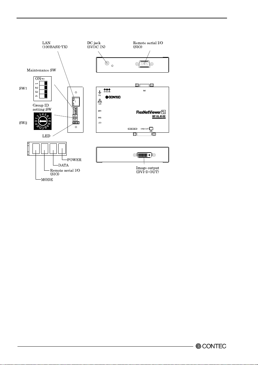
Parts of this Product and Factory Defaults
Figure 2.1. - 2.2. shows the names of major parts on this product.
Note that the switch setting shown below is the factory default.
RP-VL-S-02 (transmitter)
Figure 2.1. Component Location < RP-VL-S-02 (transmitter) >
RP-VL-S-02, RP-VL-R-02
9
Page 15
2. Setup
RP-VL-R-02 (receiver)
Figure 2.2. Component Location < RP-VL-R-02 (receiver) >
RP-VL-S-02, RP-VL-R-02
10
Page 16

2. Setup
Setting the Group ID
You must set the same Group ID for both the transmitter (RP-VL-S-02) and the receiver (RP-VL-R-02)
in order to allow the receiver to receive image data sent by the transmitter.
The Group ID can be set within the range of 0 – Eh (*) and up to 15 groups can be distinguished.
If you want to use one group only, use the factory setting (Board ID = 0).
* “F” is an ID for maintenance purposes.
Setting Procedure
To set the group ID, use the rotary switch on this product.
Turn the SW2 and then set it by using the flathead screwdriver.
Figure 2.3. Group ID Settings (SW2)
RP-VL-S-02, RP-VL-R-02
11
Page 17

2. Setup
Setting the Maintenance SW
You may be required to set the maintenance switch when setting the main unit or updating the firmware.
Setting method
The following table describes the operations of the maintenance SW.
Figure 2.4. Setting the Maintenance SW (SW1)
Table 2.1. Setting of Each SW No.
SW No. Status Indicator
(Transmitter
only *1)
2
(Transmitter
only *1)
3
4 - Initializes setting information. (Set SW No. 3 to ON and then start in recovery mode.)
Do not alter the initial setting (“off”) of the receiver.
*1
*2 To perform settings or maintenance such as upgrading the firmware, temporarily suspend any transmission
beforehand.
*3 For details about how to recover the firmware, refer to the document file for the main unit management utility.
ON Suspends the transmission of image data temporarily. *2 1
OFF Starts the transmission of image data. *2
Composite input mode
ON
Turn this switch on when using composite input.
OFF DVI input mode
Turn this switch off when using DVI input.
ON Starts in recovery mode.
This is used to recover the firmware, when corrupted, or to initialize setting information. *3
OFF Starts in normal mode.
Set this SW No. to OFF for normal use.
When this switch is turned ON, four LEDs start flashing. If it is turned off while the
LEDs are still flashing (about 3 seconds), the setting information is initialized.
* Before restarting or turning off the power, make sure that the four LEDs have stopped
flashing simultaneously.
RP-VL-S-02, RP-VL-R-02
12
Page 18

2. Setup
LED
Indicates the operational status of the main unit.
Figure 2.5. LED display
Table 2.2. LED display
LED Status Indicator
POWER
DATA
Remote
serial I/O
(Only receiver
flashing)
MODE
(Only
transmitter
flashing)
Flashing Being initialized and started in recovery mode.
OFF The power is not supplied.
OFF
Flashing
OFF
Flashing SIO data is being transferred.
OFF
*If this state remains unchanged over one minute when launching with the
maintenance switch (SW1) SW No. 3 off, the firmware may be defective.
ON Firmware in operation.
(Transmitter) No image signal output.
(Receiver) The transmitter is not sending signals as the PC connected to the
transmitter being turned off or the DVI cable, video cable or LAN cable for the
DVI-D being disconnected.
(Transmitter) Image signal being output.
ON
(Receiver) The transmitter is sending signals as the PC connected to the transmitter
being turned on and the DVI cable, video cable and LAN cable for the DVD-D being
connected.
(Transmitter) Image signal being transferred.
(Receiver) The image signal is being output from the receiver to the monitor.
SIO data transfer is not being performed.
SIO is connected.
ON
Set to DVI input mode.
Set to composite input mode.
ON
RP-VL-S-02, RP-VL-R-02
13
Page 19

2. Setup
Checking the IP Address
The IP address of this product when it is delivered is shown on the product label on its reverse side.
Transmission can be made between the receiver and the transmitter with the factory settings.*1
*1 The IP address and network mask for the same network must be set when transmitting by LAN. Use the main management utility
(FNVHD-UTM) for altering the IP address.
Settings Using the Software
The main management utility (FNVHD-UTM) software application is provided for making settings for
the transmitter and receiver through your PC (available for downloading from our Web site for free).
Using the main management utility (FNVHD-UTM) allows you to make the following settings remotely
(via LAN). Use it as necessary.
- Changing the IP address
- Update of firmware
- Confirmation of sending / receiving status
etc.
Set the IP address and network mask of the same network as the transmitter (RP-VL-S-02) and receiver
(RP-VL-R-02) for PCs installed with the main management utility.
Refer to the document file included with the downloaded main management utility in regards to detailed
information on the main management utility.
URL: http://www.contec.com/
RP-VL-S-02, RP-VL-R-02
14
Page 20

2. Setup
Setup Method
Table Top Installation
Set it by using the supported rubber feet.
If installing on a desktop, place the unit on a stable and flat base.
Mounting the Product on the Monitor
If the optional monitor mounting adapter is used, the product can be mounted on the back of the monitor.
The monitor mounting adapter complies with the VESA standard (75mm x 75mm or 100mm x100mm).
VESA Bracket for Flex Net Viewer HD (100mm x 100mm) : BRK-VL02-100
VESA Bracket for Flex Net Viewer HD (75mm x 75mm) : BRK-VL02-75
Figure 2.6. Mounting the Product on the Monitor
Cable Tie Attachment Method
Figure 2.7. Attachment of the cable tie
CAUTION
As noise affecting the video cable connected to the Video In terminal of the transmitter may prevent
clear pictures, we recommend taking some precautions such as attaching a ferrite core in
environments with high noise.
RP-VL-S-02, RP-VL-R-02
15
Page 21

2. Setup
How to mount the DC plug attachment
(1) Connect the DC plug of th e bu ndled AC adapter to the product.
(2) Mount the DC plug attachment so that it covers the DC plug over.
(Secure it with the M3 screw.)
Figure 2.8. How to Mount DC Plug Attachment
RP-VL-S-02, RP-VL-R-02
16
Page 22

2. Setup
Startup and Stop
Always follow the startup and stop procedures in order to use the product correctly.
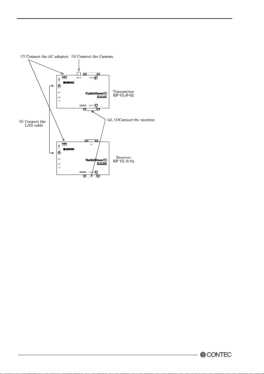
Startup procedure
< Using DVI input >
Figure 2.9. Startup procedure (Using DVI input)
(1) Prior to connecting the transmitter and receiver, set the resolution of the PC screen to one of the
resolutions this product is compatible with.*1*2
(2) Turn the transmitter maintenance switch 2 off. (Factory setting: OFF)
(3) Connect the “DVI-D IN” of the transmitter with the screen output pin of PC by using the DVI cable.
*3
(4) Connect the “DVI-D OUT” of the transmitter with the screen input pin of monitor by using the DVI
cable. *4*5
(5) Connect the “DVI-D OUT” of the receiver with the screen input pin of monitor by using the DVI
cable. *4*6
(6) Connect the “LAN”s of transmitter and receiver with a LAN cable (category 5 or higher).*6.
(7) Connect the AC adaptors provided to the transmitter and receiver respectively to supply a power.*7
Compatible resolutions:
*1:
*2: Set the refresh rate to 60Hz.
This product does not support HDCP.
*3:
Use a monitor that supports resolution(s) compatible to this product.
*4:
When only the DVI-D Out of the receiver is used, there is no need to connect it.
*5:
When directly connecting the receiver and transmitter, use a cross cable.
*6:
RP-VL-S-02, RP-VL-R-02
VGA(640x480), SVGA(800x600), XGA(1024x768), 480p(720x480), HD (1280x720).
17
Page 23
2. Setup
*7: Depending on your PC, it may start with the startup screen of which the resolution is not supported by this
product. In this case the startup screen image may be distorted or not be displayed.
< Using composite input >
Figure 2.10. Startup procedure (Using composite input)
(1) Set the camera video output specification to NTSC prior to connecting the transmitter and receiver.
(2) Turn the transmitter maintenance switch 2 on. (Factory setting: OFF)
(3) Connect the “VIDEO IN” of the transmitter with the screen output pin of camera by using the
VIDEO cable.
(4) Connect the “DVI-D OUT” of the receiver with the screen input pin of monitor by using the DVI
cable. *1
(5) Connect the “LAN”s of transmitter and receiver with a LAN cable (category 5 or higher).*2.
(6) Connect the AC adaptors provided to the transmitter and receiver respectively to supply a power.
With composite input the resolution is 480p (720 x 480p). Use a monitor compatible with 480p.
*1:
*2: When directly connecting the receiver and transmitter, use a cross cable.
Stop procedure
(1) Before terminating the product, turn off the PC, camera, monitor, LAN (HUB) and all other
peripherals.
(2) Disconnect the AC adapter which is connected to the product, and then stop the power supply.
RP-VL-S-02, RP-VL-R-02
18
Page 24

3. Function
3 Function
This section describes the features of this product.
Video Transfer Function
This function extend s the monitor screen capability by Ethernet to display screen images on a remote
monitor. Image signals (DVI signals, Composite) are converted into LAN packet signals before being
sent.
By using a commercial LAN cable, you can extend the distance of Video signal which have a limit in
their cable length.
Also, by connecting multiple receivers, multiple monitors can be used to display the input screen by.
When using the receiver and transmitter as a set, be sure to use them without placing a load on the PC
and without being dependent on the PC or operating system platform in order to be able to transfer
images through only the hardware itself.
Example of connection with a PC
Figure 3.1. Example of connection with a PC
RP-VL-S-02, RP-VL-R-02
19
Page 25

3. Function
Example of connection with a camera
Figure 3.2. Example of connection with a camera
CAUTION
- Configuration of multiple transmitters and one receiver is not possible.
- Unlimited number of receivers can be connected.
- With composite input the image is output from the receiver’s DVI output at 480p resolution. No
images are output from transmitter's DVI output.
- This product uses MPEG-4 compression, the input image cannot be completely reproduced. Please
confirm the recycled product quality of animation beforehand with lending machine.
- Do not alter the resolution with the picture signal input.
- When the screen is not normally displayed by the influence of compatibility , please change the
resolution setting of the transmitter and the receiver to the using PC resolution by using the main
unit management utility. Refer to the document file included with the downloaded main
management utility in regards to detailed information on the main management utility.
- It is likely to picture is distorted according to the environment when communicating by wireless
LAN.
- Refer to the separate Technical Reference regarding records of operating data for the monitor, PC
(graphics card) and wireless LAN. The Technical Reference is available for download from
CONTEC's website.
- Because composite input is analog signal, it is some loss of picture quality compare with DVI input.
- Please refer to the document file of the main body management utility for the setting when the
router is used.
RP-VL-S-02, RP-VL-R-02
20
Page 26
3. Function
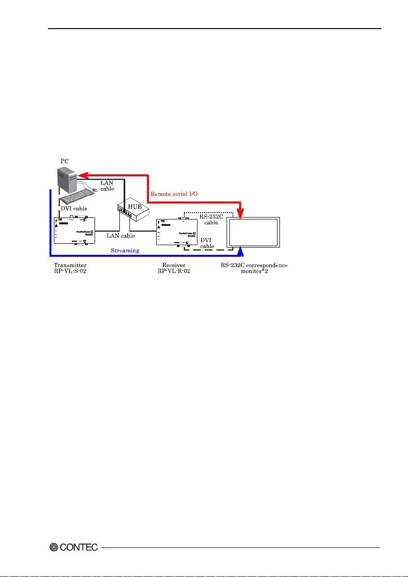
Remote serial I/O function
This function allows RS-232C equipment connected to the receiver to be remotely controlled using the
Virtual COM driver*
Using a LAN cable can extend the distance for serial data with an RS-232C-standard limitation (15m).
The baud rate of the RS-232C can be set by the Virtual COM driver between 300bps to 115,200bps.
For more details on the connector, refer to “chapter 4 About Hardware Remote Serial I/O: Pin
assignment of SIO”.
*1 Available for download free of charge from our website.
*2 Some products can be turned on or off and have their settings changed through RS232C transmission.
Figure 3.3. Configuration example of simultaneous use of remote serial I/O function and video
communication function.
The figure shown above depicts a configuration example of the simultaneous use of a remote serial I/O
function and the video communication function. The transmitter is not necessary if the video
communication function is not used.
1
produced by CONTEC (This function is available only for the receiver.).
RP-VL-S-02, RP-VL-R-02
21
Page 27
3. Function
Image transfer utility (option)
Your PC can be used as a transmitter or receiver by using the optional (separately sold) image transfer
utility. For details, refer to the documentation of the image transfer utility.
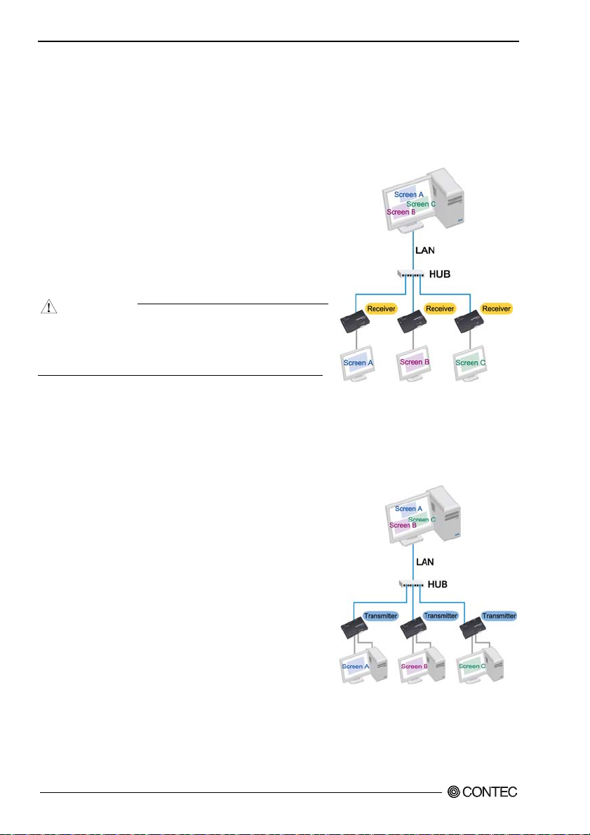
Controlling display screens in remote locations by Windows PCs
A Windows PC can be used as a host computer to
communicate with multiple monitors in a remote location to
transfer different screen image to each of them.
The screen data is communicated from the Windows PC
(with the optional image transfer utility), eliminating the
need for a transmitter.
CAUTION
In Windows XP or 2000, when another application
window is placed in front of the application window to
be displayed on the remote monitor, the screen data of
the overlapping windows is transferred.
Figure 3.4. Configuration example
showing scheme of controlling the
display screens in a remote location
by a Windows PC
Monitoring c omputer display screens in remote locations
The computer display screens of multiple PCs in remote
locations can be received by a Windows PC and monitored
on a multiple windows display.
The screen data is received by the Windows PC (with the
optional image transfer utility), eliminating the need for a
receiver.
Figure 3.5. Configuration example
showing scheme of monitoring the
computer display screens in remote
locations
RP-VL-S-02, RP-VL-R-02
22
Page 28

4. About Hardware
4 About Hardware
This chapter provides hardware specifications and hardware-related supplementary information.
Hardware specification
Table 4.1 shows the specification of this product.
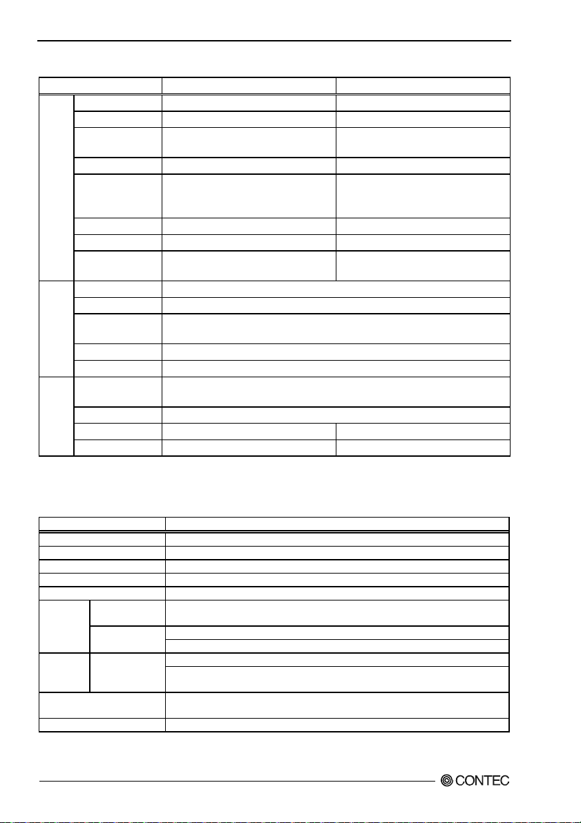
Table 4.1. Specification <1/2>
Item RP-VL-S-02 (Transmitter) RP-VL-R-02 (Receiver)
Input pin DVI-I connector x 1 *1 *2 None
DVI
Output pin DVI-I connector x 1 *1
Supported resolution VGA (640 x 480), SVGA (800 x 600), XGA (1024 x 768), 480p (720 x 480),
720p (1280 x 720), 1080i (1920 x 1080 / Receiver only) *3
Horizontal frequency
Vertical frequency
Max. frame rate 30fps *4*5
Network load factor
Allowable distance of
signal extension
Input pin RCA connector x 1 None
VIDEO
(Compo
Signal standard NTSC None
site)
Supported resolution 480i (720 x 480) *6 None
Horizontal frequency
Vertical frequency
Max. frame rate 30fps *4*5 None
Network load factor
Allowable distance of
signal extension
Only compatible with digital (DVI) signals. Analog input or output is impossible even with a DVI-RGP conversion cable
*1:
(connector).
*2: This product does not support HDCP.
It is possible only to use Image transfer utility of the option. When output at 1080i, use a monitor that supports interlaced input.
*3:
*4: When the resolution setting is set besides "Automatic operation", e
resolutions are as follows.
VGA: 30fps, SVGA: 30fps, XGA: 24fps, 480p (480i): 30fps, 720p: 24fps, 1080i: 5fps
When the resolution setting of this product is "Automatic operation", the maximum frame rate might not be output.
Moreover, it depends on specs of PC used when the image transfer utility is used. Please refer to the document of
the image transfer utility for details.
These will change according to the image being shown and the resolutions actually used.
*5:
This is the resolution compatible with the transmitter input. The receiver outputs at 480p (720 x 480).
*6:
*7: The actual extendable signal distance may be shorter, depending on the material and wiring conditions of the cable used.
VGA: 31.50kHz, SVGA: 37.90kHz, XGA: 48.40kHz, 480p: 31.50kHz, 720p: 45.00kHz,
1080i: 33.75kHz
60Hz
8% *5
Within 5m
15.73kHz None
60Hz None
8% *5 None
Within 20m *7 None
stimated correspondences between frame rates and
RP-VL-S-02, RP-VL-R-02
23
Page 29
4. About Hardware
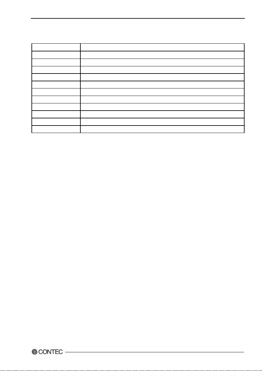
Table 4.1. Specification <2/2>
Item RP-VL-S-02 (Transmitter) RP-VL-R-02 (Receiver)
Serial
I/O pin None 9 pin D-SUB x 1
I/O
Channel No. None 1ch
I/O specification None RS-232C
(TXD, RXD, RTS, CTS, DTR, DSR)
Transmission mode None Asynchronous
Baud rate None 300bps,1200bps,2400bps,4800bps,9600bps,
19200bps,38400bps,57600bps,115200bps
*9
Data length None 7, 8 bit 1, 2 stop bit *9
Parity check None Even, odd, No parity *9
Allowable distance of
signal extension
I/O pin RJ-45 connector x 1
LAN
Ethernet standard IEEE802.3u (100BASE-TX)
Data transmission
speed
Transmission method
Transfer mode UDP, TCP, DHCP, IP, ARP
Physical dimensions
Others
(mm)
Power supply AC adapter 5VDC 2A (Max.) (bundled with this product)
Power consumption 5VDC 700mA(Max.) 5VDC 450mA(Max.)
Weight 267g 264g
*8: The actual extendable signal distance may be shorter, depending on the material and wiring conditions of the cable used.
Settings can be made with the Virtual COM driver.
*9:
Table 4.2. Installation Environment Requirements
Item Requirement description
Operating temperature 0 - 50°C
Storage temperature -10 - 60°C
Operating humidity 10 - 90%RH (No condensation)
Floating dust particles Not to be excessive
Corrosive gases None
Noise
immunity
resistance
Impact resistance 15G half-sine shock for 11ms in X, Y, and Z directions
Grounding Class D grounding (previous class 3 grounding) , SG-FG/continuity
Line-noise AC line / 2kV, Signal line / 1kV
Static electricity
resistance
Sweep resistance
None Within 15m *8
100Mbps (100BASE-TX)
Half Duplex, Full Duplex
123(W) x 77(D) x 26(H)
(IEC1000-4-4Level 3, EN61000-4-4Level 3)
Contact discharge / 4kV (IEC1000-4-2Level 2, EN61000-4-2Level 2)
Atmospheric discharge / 8kV (IEC1000-4-2Level 3, EN61000-4-2Level 3)
10 - 57Hz / semi-amplitude 0.15mm, 57 - 150Hz / 2.0G Vibration
40minutes each in X, Y, and Z directions
(JIS C60068-2-6-compliant, IEC60068-2-6-compliant)
(JIS C60068-2-27-compliant, IEC60068-2-27-compliant)
RP-VL-S-02, RP-VL-R-02
24
Page 30
4. About Hardware
Table 4.3. AC adapter environmental condition (environmental specification)
Parameter Requirement description
Input voltage range *1 100 - 240VAC 50Hz/60Hz
Rated input current
Frequency 47 - 63Hz
Rated output voltage 5.0VDC (at the time of 0A - 2.0A)
Rated output current 2.0A (Max.)
Operating temperature 0 - 40°C
Storage temperature 20 - 80%RH (No condensation)
Floating dust particles Not to be excessive
Corrosive gases None
Physical dimensions(mm) 50(W) x 78(D) x 31.5(H) (Not including the cable and protrusions)
Weight 157g
*1 The bundled AC cable is for 125VAC.
AC400mA (100VAC,50Hz, at maximum load)
RP-VL-S-02, RP-VL-R-02
25
Page 31
4. About Hardware
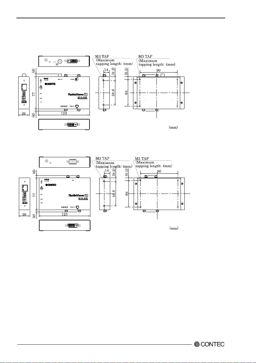
Physical dimensions
RP-VL-S-02 (transmitter)
Figure 4.1. Physical dimensions < RP-VL-S-02 >
RP-VL-R-02 (receiver)
Figure 4.2. Physical dimensions < RP-VL-R-02 >
RP-VL-S-02, RP-VL-R-02
26
Page 32

4. About Hardware
AC Adapter
Figure 4.3. Physical dimensions < AC Adapter >
Depending on manufacture time, the bundled AC cable may be un-double insulation.
※
RP-VL-S-02, RP-VL-R-02
.
27
Page 33
4. About Hardware
Interface Connector
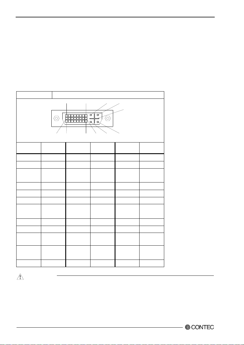
Image input, Image output: Pin assignment of DVI-D IN, DVI-D OUT
DVI input is available only with the transmitter. DVI output is available with both the transmitter and
receiver.
Table 4.4. DVI-D IN, DVI-D OUT connector
Connector used DVI-I 29 pin
1
8
C1
C2
C5
16
17
9
Pin No.
1 DATA2- 13 N.C. C1 N.C.
2 DATA2+ 14 +5V C2 N.C.
3
4 N.C. 16 HPD C4 N.C.
5 N.C. 17 DATA0- C5 GND
6 DDC CLK 18 DATA0+
7
8 VSYNC 20 N.C.
9 DATA1- 21 N.C.
10 DATA1+ 22
11
12 N.C. 24 CLK-
Signal
name
DATA2
SHIELD
DDC
DATA
DATA1
SHIELD
24
Pin No.
15 GND C3 N.C.
19
23 CLK+
Signal
name
DATA0
SHIELD
DATA0
SHIELD
C4
C3
Pin No.
Signal
name
CAUTION
- Although this product uses DVI-I connectors they do not support analog input and output.
Accordingly, even with the use of a DVI-VGA conversion cable, signal conversion to VGA input
(output) is unavailable.
- Erroneous connection can lead to malfunction of this product or peripheral equipment. In order to
prevent degradation of the signal, we recommend the use of as short a cable as possible.
RP-VL-S-02, RP-VL-R-02
28
Page 34

4. About Hardware
- If input to the transmitter is at 1080p resolution, it will be output from the receiver at 1080i. When
output at 1080i, use a monitor that supports interlaced input.
Image input: Pin assignment of VIDEO IN
Composite input is only included with the transmitter.
Table 4.5. RCA connector
Remote serial I/O: Pin assignment of SIO
The remote serial I/O is only included with the receiver.
Baud rate: 300 - 115200bps (Can be set by software.)
Table 4.6. Remote serial I/O connector
Connector
used
Pin No. Signal name Pin No. Signal name
1 N.C. 6 DSR
2 RXD 7 RTS
3 TXD 8 CTS
4 DTR 9 N.C.
5 GND
CAUTION
Communication may not be possible, if the following devices are connected:
- Device that uses RI or DCD signals
- Device that requires a RS-232C communication response above a certain level such as
programming during RS-232C communication
- Device that uses control signals such as RTS and CTS for special purposes, etc.
D-SUB 9pin (MALE)
15
6
9
RP-VL-S-02, RP-VL-R-02
29
Page 35

4. About Hardware
LAN: Pin assignment of LAN connector
LAN connector is available with both the transmitter and receiver.
Table 4.7. Ethernet connector
Connecto
r used
RJ-45
81
LINK ACT
Pin No. Signal name Meaning
1 TD+ Transmitted data(+)
2 TD- Transmitted data(-)
3 RD+ Received data(+)
4 N.C. Not connected
5 N.C. Not connected
6 RD- Received data(-)
7 N.C. Not connected
8 N.C. Not connected
Network status display LED
LINK : Link status indicator
ACT : Data send/receive indicator
CAUTION
- Use LAN cables of Category 5 or higher.
- 10BASE-T(10Mbps) is not supported.
RP-VL-S-02, RP-VL-R-02
30
Page 36

4. About Hardware
DC Jack: Pin assignment of 5V DC-IN
DC Jack is available with both the transmitter and receiver.
+5V
GND
Figure 4.4. DC Jack
CAUTION
- Do not connect any AC adapter other than the AC adapter bundled with the product, or a device
failure or accident may occur.
- Once the AC adapter is turned on, do not rotate or vibrate the DC plug.
RP-VL-S-02, RP-VL-R-02
31
Page 37

RP-VL-S-02
RP-VL-R-02
User’s Guide
CONTEC CO., LTD. March 2013 Edition
3-9-31, Himesato, Nishiyodogawa-ku, Osaka 555-0025, Japan
Japanese http://www.contec.co.jp/
English http://www.contec.com/
Chinese http://www.contec.com.cn/
No part of this document may be copied or reproduced in any form by any means without prior written
consent of CONTEC CO., LTD. [03222013]
[09092010] Management No. NA00896
03222013_rev3 Parts No. LYLU593
 Loading...