

Page 1

Gima S.p.A.
Via Marconi, 1 – 20060 Gessate (MI) Italy
gima@gimaitaly.com – export@gimaitaly.com
www.gimaitaly.com
PROFESSIONAL MEDICAL PRODUCTS
100G CONTEC ECG - 1 channel with monitor
User Manual
ATTENTION: The operators must carefully read and
completely understand the present manual before
using the product.
33220
CONTEC MEDICAL SYSTEMS CO., LTD
No. 112 Qinhuang West Street, Economic & Technical Development Zone,
Qinhuangdao, Hebei Province, PEOPLE'S REPUBLIC OF CHINA
Shanghai International Holding Corp. GmbH (Europe)
Eiffestrasse 80, 20537, Hamburg, Germany
Page 2

User Manual
I
CONTENTS
Chapter 1 Main Technical Specification ..................................................................................... 1
Chapter 2 Security Notice .......................................................................................................... 2
Chapter 3 Maintenance Regulation ........................................................................................... 3
Chapter 4 Apparatus Characteristic ........................................................................................... 4
Chapter 5 ECG100G Panel Sketch Map ................................................................................... 6
Chapter 6 Operation Regulation ................................................................................................ 9
Chapter 7 Preparation before Operation ................................................................................. 10
Chapter 8 Attention During Operation ..................................................................................... 11
Chapter 9 Recording Paper Loading ....................................................................................... 12
Chapter 10 Electrode Installation ............................................................................................. 13
Chapter 11 Grounding and Power Connection ........................................................................ 16
Chapter 12 Battery Operation Regulation ................................................................................ 17
Chapter 13 Keypad and Controls ............................................................................................. 18
Chapter 14 Troubleshooting ..................................................................................................... 21
Chapter 15 Maintenance Transportation And Preservation ..................................................... 23
Appendix ..................................................................................................................................... 24
Page 3

User Manual
1
Chapter 1 Main Technical Specification
1.1 Normal work environment
Operation
a) Environment temperature: +5℃~+35℃
b) Relative humidity: ≤80%
c) Power supply: AC:100~240V,50/60 Hz
DC: 7.4V, 2000 mAh rechargeable lithium battery
d) Atmospheric pressure: 86kPa~106kPa
Store and Transportation
a) Environment temperature: -40℃~55℃
b) Relative humidity: ≤95%
c) Atmospheric pressure: 50kPa~106kPa
1.2 Input way: Floating and defibrillation protection
1.3 Lead: Standard 12 leads
1.4 Patient leak current: <10µA
1.5 Input impedance: ≥50MΩ
1.6 Frequency response: 0.05Hz~150Hz (-3dB)
1.7 Time constant: Time constant>3.2s
1.8 CMRR: >60dB, >100Db ( Add filter)
1.9 EMG interference filter: 35Hz (-3dB)
1.10 Recording way: Thermal printing system
1.11Specification of recording paper: 50mm(W)*20m(L) High-speed thermal paper
1.12 Paper speed: 25mm/s, 50mm/s, error:±5%
1.13 Sensitivity choice: 5,10,20mm/mV, error:±5%.Standard sensitivity is 10mm/mV±0.2mm/mV
1.14 Auto-record: according the record format and auto-mode to set, auto leads-changing, auto
measurement.
1.15 Manual record: according the record format to record, manual leads-changing.
1.16 Classification: Class I, CF applied part
1.17 Enduring polarization voltage: ±300mV
1.18 Noise level: ≤15µVp-p
1.19 Fuse Specification: 2 pcs φ5*20mm AC time lag; T1.6AL250V (Power Supply:220V)
1.20 Size: 315mm(L)*215mm(W)*77mm(H)
1.21 Net Weight: 2.25Kg
Page 4

User Manual
2
Chapter 2 Security Notice
2.1 Make sure the instrument grounding properly during installation.
2.2 If the ground cable is not integrated, please run the device with battery.
2.3 Please pull out power supply plug before change the fuse.
2.4 This device must be operated and preserved by professional doctor.
2.5 The operator must read this user manual carefully before operation, and operate the device
according to operation regulation strictly.
2.6 The design of this device with mature consideration of security, but operator should never
neglect attention to device state and patient’s situation.
2.7 Please dismantle the battery and pull out power supply plug before cleanout and
disinfection of this device.
2.8 Please don’t operate this device in the environment which contains flammable anaesthesia
gas.
2.9 If use this device with cardiac defibrillator or other electric stimulate devices at same time,
please
use our company’s Ag-AgCl chest electrode and ECG lead, if use the electric stimulate device
over 55
seconds, please choose one-off chest electrode. We suggest ECG100G not be used with other
electric
stimulate device, if it is compulsory, there should be professional technician guided on the
scene.
2.10 When other devices are connected with this ECG instrument, they must be Type I devices
which accord with IEC60601-1. Because the total amount of leakage current may hurt patients,
the monitoring of leakage current is carried out and taken charge by connect devices.
2.11 Replacing part: record paper :50mm(W)*20m(L)
2.12 To avoid the danger that the heart pacemaker and other electric stimulate cause ,this
system is electric separate ,separating people and the machine electric absolutely.
2.13 Electrocardiograph can indicate abnormal state, caused by overloaded or any part of the
amplifier saturation.
Page 5

User Manual
3
Chapter 3 Maintenance Regulation
3.1 Under the condition of normal use according to the user manual and operation notice, if this
instrument has any problem, please contact with our customer service department. Our
company has the sales record and customer archives for each instrument. The customer has
one year's warranty service from the beginning of shipping date according to the below time
and condition. To supply all-around and fast maintenance service to our customers, please mail
the maintenance card to us in time.
3.2 Our company may adopt the ways of instruction, mailing to company by courier, visiting
customers' company, etc to carry out the maintenance promise.
3.3 Even in the period of free maintenance, we charge for reparation in the following archives:
3.3.1 Faults or damnification caused by misuse because not operate according to user manual
and operation notice.
3.3.2 Faults or damnification caused by dropping accidently when users move after purchasing.
3.3.3 Faults or damnification caused by preparation, reconstruction, decomposition, etc outside
of our company.
3.3.4 Faults or damnification caused by natural disasters such as fire, flood, earthquake, etc.
3.3.5 Faults or damnification caused by unapt thermal recording paper.
3.4 The free maintenance period for spare parts and fray parts is half a year.Power cable,
recording paper, operation manual and packing material are excluded.
3.5 Our company is not responsible for the faults of other connecting instruments caused by the
faults of this device directly or indirectly.
3.6 The free maintenance service will be canceled if we find the protection label has been
destroyed.
3.7 For charge maintenance beyond the warranty period, our company advise to continue to
use "Maintenance contract regulation". Please consult our customer service department for
specific situation.
Page 6

User Manual
4
Chapter 4 Apparatus Characteristic
4.1 Recording system: Thermal-array (8 dots/mm), it needs not be adjusted. Frequency
Response: 150Hz
(IEC).
4.2 The device can record exact single ECG waveform and remark. The remark includes: lead
sign,
sensitivity, paper speed, filter state.
4.3 Under automatic mode, just press the button once, it starts record procedure, which can
enhance your
work efficiency.
4.4 The keyboard is convenient to operate, and the LCD can display the operation state, which
is convenient and readable.
4.5 Classification: Class: I, CF applied part.
4.6 The device can use AC and DC and it includes built-in chargeable lithium battery.
4.7 This instrument can record 150 pieces of ECG waveform and print 90 minutes continually
under the best DC state.
4.8 The figure of whole device is elegancy and gliding.
4.9 According to defendence degree of deleterious fluid, this device is belong to common
device.
4.10 The device can’t be used in the environment, which contain flammable anaesthesia gas
mixed with
Air.
4.11 Adopting digital signal which deals with the work filter, the baseline filter and the EMG filter
will obtain the higher quality of the ECG.
4.12 The device can AUTO print the normal ECG, which can lighten the doctor's burden and
enhance your work efficiency.
4.13 According to the working mode class, this device belongs to continuous operation
equipment.
4.14 Function: This equipment is digital single channel electrocardiograph, which connects with
people though lead wires, filter and amplify the faint signal it gathers ,then transmit to the single
chip microcomputer. The single chip microcomputer then processes the signal through some
algorithms to get waves to send to the LCD and the printer, which supply to the user.
4.15 Intended use: doctor or professional may diagnose the state of the patient through
observing the waves the ECG offers, then take measures according to the result.
4.16 Explanation of some symbols in this device:
~AC AC work mode
OFF Power supply is disconnected
ON Power supply is connected
Page 7

User Manual
5
Equipotential point
Places need to be noticed, please refer to user manual
Device type is CF applied part, which has defibrillation protection function
PATIENT Lead connector
WEEE (2002/96/EC)
This item is compliant with Medical Device Directive 93/42/EEC of June 14,
1993, a directive of the European Economic Community.
Page 8

User Manual
6
Chapter 5 ECG100G Panel Sketch Map
A. The sketch map and components name
Front view
Side view
Page 9

User Manual
7
Rear view
Bottom view
B. Button definition
Function button: ON/OFF & Time Display
Function button: plus adjust
Function button: paper speed adjust
Function button: filter function select
Function button: pause/on
Function button: switch work mode
Function button: marker
Function button: print
Power Switch Power Plug Earth Terminal
Page 10

User Manual
8
Function button: system menu
Function button: upwards
Function button: downwards
Function button: leftwards
Function button: rightwards
C. Indicator Definition
The indicator turns green when there is AC power supply, and when the indicator
turns green and red same time it is being recharged.
Indicator for instrument when power on.
Page 11

User Manual
9
Chapter 6 Operation Regulation
6.1 You are required to read the operation regulation so as to ensure taking proper operation of
the instrument.
6.2 Installation and maintenance of the instrument shall be carried out as the following:
6.2.1 There shouldn't have high voltage cable, X radial engine, ultrasound instruments and
electrotherapeutics engine around the ECG.
6.2.2 Do not install the instrument in the place where it might be affected by bad humidity and
ventilation, direct sunlight, as well as air containing dust, salt, and sulphur, etc.
6.3 The device should be placed in evenness ,and move gently, and should avoid the strong
vibration and impact.
6.4 AC frequency and voltage value should be accorded with the need and the current capacity
should be enough..
6.5 Do the instrument grounding properly during installation. Don't put the patients and the lead
which connect with patients contact with other conductors, including the ground or the sickbed
which ground properly.
6.6 Please ensure the device operated in the range of environment temperature: 5℃~35℃. If
the device is reserved in higher temperature or lower temperature environments, please wait for
about 10 minutes before using it, to ensure normal operation of the device.
Page 12

User Manual
10
Chapter 7 Preparation before Operation
7.1 Check that the instrument properly grounded and that cable connections safe or not.
7.2 Check the electrode which connected with patient safe or not
7.3 When power supply is direct current (UPS), please check the voltage of battery before use.
7.4 The gel should be separated from each other and the chest electrodes shouldn't be
contacted with the others, as this operation can avoid short circuit.
7.5 The AC power supply cable and leads should be separated.
Page 13
User Manual
11
Chapter 8 Attention During Operation
8.1 Keep close observation of state of the patient and instrument.
8.2 Make sure that the patient and device only be connected by leads.
8.3 The device and patient can’t be moved during working.
8.4 Turn off device after operation.
8.5 Pull out the power supply plug, then move the leads lightly.
8.6 Tidy up the devices and accessories for next use.
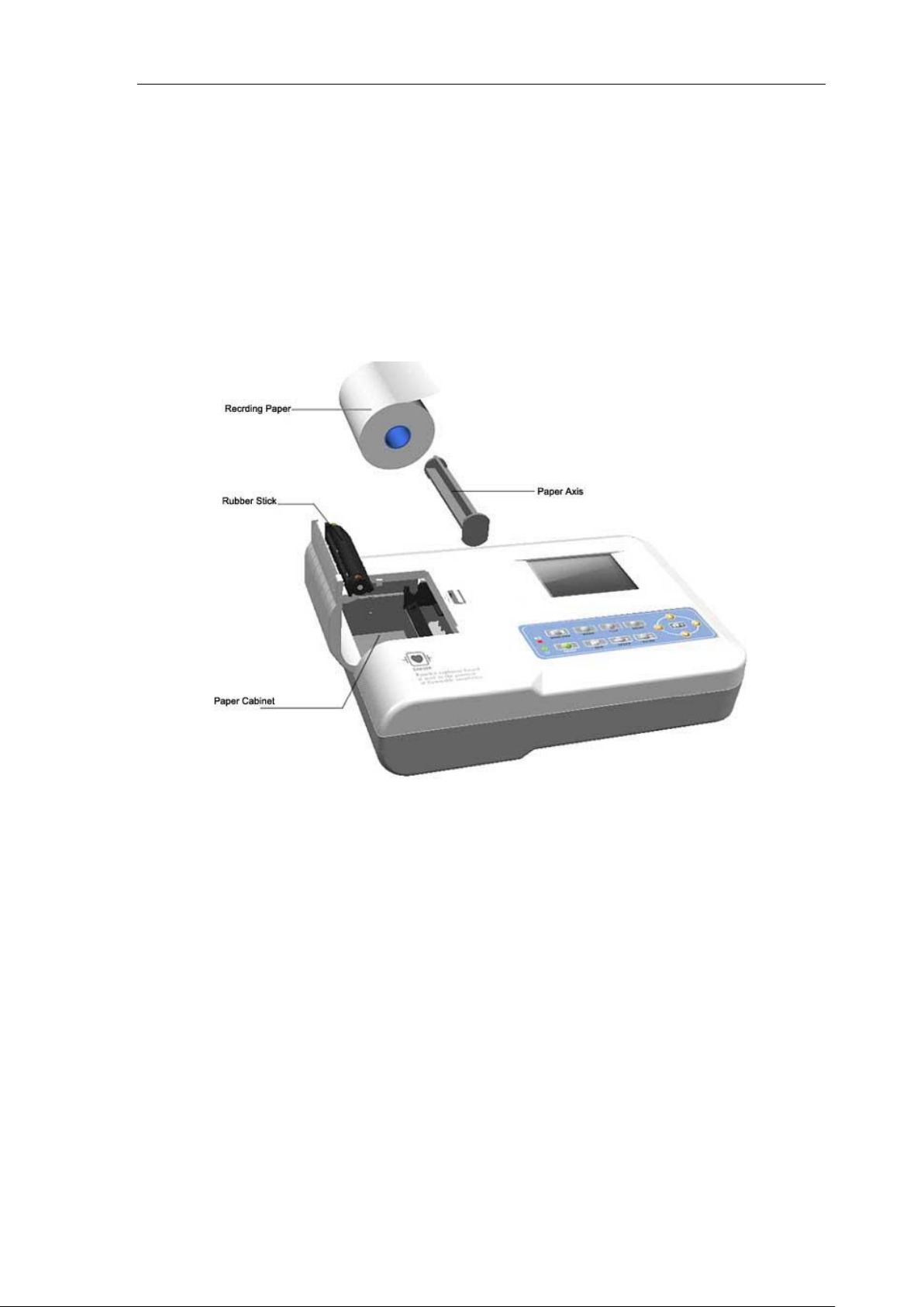
8.7 The installation recording paper.
8.7.1 This device use high-speed thermal paper whose specification is 50mm(W)*20m(L) .
8.7.2 First, open the paper cabinet, take out the paper axis, then put the paper axis in recording
paper, then put it in the relevant position of paper cabinet.
8.7.3 Cover the paper cabinet with paper cabinet cover, 2cm of the beginning of paper should
be left out of the cabinet exit.
Page 14

User Manual
12
Chapter 9 Recording Paper Loading
9.1 If the recording paper is used up during the recording process, the paper record will over,
and a notice will be displayed on the LCD screen.
9.2 There is a line at the verge of paper at the last two meters of the recording paper, this line
means the paper is not enough, please change the paper immediately. We suggest you
choose our company’s print paper, as for its detailed information, please consult with our
company or agency.
9.3 The possible reason which will make the recording paper disable includes: high temperature,
humidity, and sunshine irradiation. The recording paper which needs long time stock should be
deposit in dry, dark and cool environment.
9.4 The instance which may contaminate the recording paper. Gel, glue, and wet diazo
compound paper including their organic solvent.
9.5 The materials that may cause the record wave disappear: the folder contain soft PVC;
plastic; the demagnetize ware and tape contain elasticizer; the high-lighter pen, stamp-pad ink,
and so on.
Notes: When using up the record paper every time, store it together and do not throw it
everywhere.
Page 15

User Manual
13
Chapter 10 Electrode Installation
You'd better install the chest electrode firstly, then Limb electrode.
10.1 Chest electrode, as shown in figure 10-1:
Figure 10-1: chest electrode locations
The position of installing chest electrodes are as following:
V1: Fourth inter-costal space at right border of sternum.
V2: Fourth inter-costal space at left border of sternum..
V3: Midway between V2 and V4.
V4: Fifth inter-costal space at left mid-clavicular line.
V5: Left anterior axillary line at the horizontal lever of V4.
V6: Left mid-axillary line at the horizontal lever of V4.
Cleaning the chest skin with alcohol, then put the gel in the diameter about 25mm and the edge
of the chest electrodes ,press the ball of the chest electrodes, the chest electrodes will be
attracted in the position of V1-V6.
Attention: The chest electrodes should be separated from gel coats, this operation can avoid
short circuit.
10.2 Limb electrode
Figure 10-2:Limb electrode locations
Clean all the limb electrodes and the positions around to which limb electrodes are to be
attached with alcohol before applying ECG cream to them, then firmly attach the electrodes to
the positions.
Attention: the fix knob should be screwed down tightly after lead connected with main
Page 16

User Manual
14
unit.
Page 17

User Manual
15
10.3 Check-List for Electrode connection and ECG cable
Electrode Location
Electrode Code
Socket Number
Right Alarm
RA/R
9
Left Alarm
LA/L
l0
Left Leg
LL/F
11
Right Leg
RL/N
14
Chest 1
Vl/Cl
12
Chest 2
V2/C2
1
Chest 3
V3/C3
2
Chest 4
V4/C4
3
Chest 5
V5/C5
4
Chest 6
V6/C6
5
Notes: When using up the absorption ball, clear the clamp used for arms and legs and
put on the appointed place to store.
Page 18

User Manual
16
Chapter 11 Grounding and Power Connection
Make sure the status of the instrument is power off, and then make the instrument be properly
grounded through a 3-prong outlet. When the outlet, a grounding cable may be utilized to
connect the grounding terminal of the instrument. Do not use other pipeline. Properly grounding
could guarantee the safety and prevent from the interference of AC power and electromagnetic
wave.
Page 19
User Manual
17
Chapter 12 Battery Operation Regulation
12.1 This device includes built-in chargeable lithium battery, which needn’t maintenance. This
battery is with perfect automatic charge and discharge monitoring system. When you connect
power supply adapter with alternating current, the charge will be start automatically. When this
device be open, an icon be displayed on top right corner of LCD screen. means the
battery is charging. The whole charge process needs four hours.
12.2 When the battery is full, the device can be operated for one hour, when the battery be used
as power supply, An icon of battery will be displayed in the LCD screen of front panel, this icon
includes five degree indicates power of battery. When the battery is power off, the device will
turn off automatically, this setting is for avoiding permanent damage on battery caused by
excessive discharge.
12.3 Please charge the battery after power off. When this device be deposit for long time, the
battery should be charge once every six months, this operation will prolong the use –pan of
battery.
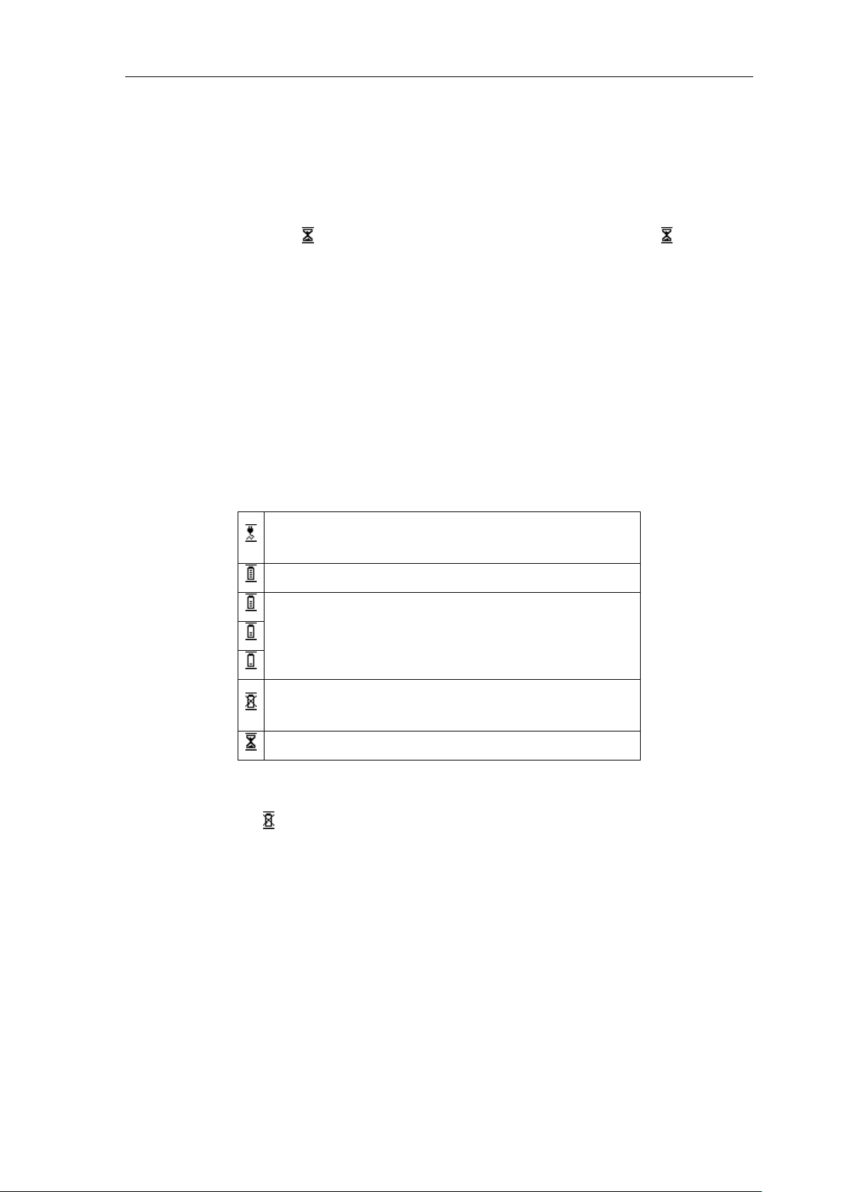
12.4 The icon of seven different state of power supply as following:
The alternating current is power supply & the battery is
full or no battery
The battery is only power supply and its power is full.
The battery is only power supply and its power is not
full
The battery is only power supply and its power is
exhausted.
Charge up
12.5 If the battery is full, but the power of battery is exhausted within 10 minutes. Please change
new battery. If the battery is can’t be charged, please change new battery.
12.6 When the icon display on screen. Please charge the battery immediately, or the device
will turn off.
Warning
Please don’t connect the anode and cathode with lead of battery directly, it will cause
danger.
Please don’t put the battery on fire. It may cause explosion.
Please don’t disassemble the battery privately.
The battery should be take gently, please don’t strike it with other article.
Page 20

User Manual
18
Chapter 13 Keypad and Controls
13.1 Press power supply key for several seconds, the device will enter auto-check
mode, at this time, the display will be boot-strap menu.
13.2 After auto-check mode, the display as following:
(1) The operation of lead indicate column
Press button to choose relevant lead, the device will switch to appointed lead check
state, it switch among according following order: I II III aVR aVL aVF Vl V2 V3
V4 V5 V6.
(2) The operation of system state information column:
Switch by press relevant function key (The function key as following)
Sensitivity: 5mm/mV,10mm/mV,20mm/mV, three kinds of sensitivity in all.
Switch Mode: MANU,AUTO.
Under AUTO-MODE, the device will note 12 leads, 3 second ECG signal every lead.
Filter: OFF,50Hz,60Hz,50Hz+,60Hz+,five filter mode in all.
The mode of 50Hz+ & 60Hz+ mean open 35Hz EMG filter.
Attention: The range of recording R wave will be fallen a little, which caused by attaching
the EMG filter.
Speed: 25mm/s,50mm/s. two kind of paper speed in all.
(3) Leads state indication.
When the leads state is "NORM" , you can print the ECG.
When the leads state is "OVER", you can’t print the ECG, please check whether electrodes are
placed well. Stop printing and print date again after collecting the wave.
When the leads state is "SAT", printed ECG is disordered, please check whether electrodes are
Page 21

User Manual
19
placed well. Stop printing and print date again after collecting the wave.
When the leads state is "DROP", leads shown on the screen have been off .Please reconnect
them.
(4) Print operation
Press under this state, you can start print system setup and ECG wave, press
again the device will be turned off.
Attention: when the paper cabinet is empty, press or , the device will
indicate no paper, please put in the paper then press .
(5) Mark operation
Press you can print a lmv standard voltage marker, which is helpful to know current
sensitivity.
Attention: the marking procedure is automatically, after this procedure you need not
press any key, the interface will be back automatically.
(6) Operation of waveform frozen
Press you can freeze current waveform in LCD screen, which is helpful for preview.
Press again, back to previous interface.
(7)Operation of turning off
Press for several seconds, the device will be turned off.
13.3 System menu
English version
Chinese version
(1) Operation of menu
菜单
背光 99s
对比度 10
语言 中文
演示模式 ON
关于 版本号
Menu
Backlight 99s
Contrast 10
Language English
Demo ON
About Ver.
Page 22

User Manual
20
Press to enter above interface, you can choose relevant item by press , then
you can press to adjust the content, after setup, press to be back.
(2)Introduction of every item
Backlight: 0-99seconds, back light start time, when choosing 0s, the back light will be turned
off, when choosing 99s, the backlight will be turned on for 99s.
Contrast: 00-20, please choose different contrast degree according to different device state.
Language: Several languages interface can be chosen ,such as ENGLISH and CHINESE
Demo: ON,OFF, if you need not inspection practice, just choose ON for demo.
About: Software Version.
Page 23
User Manual
21
Chapter 14 Troubleshooting
14.1 Automatic Switch off
① Please check whether the power of battery is used up. Turn off is for protecting circuit.
② Please check whether the alternating current voltage is too high, Turn off is for protecting
circuit.
③ Please check whether the alternating current disturb too high, whether the fix knob of lead
plug too tight. shut automatically is for protecting circuit when overload.
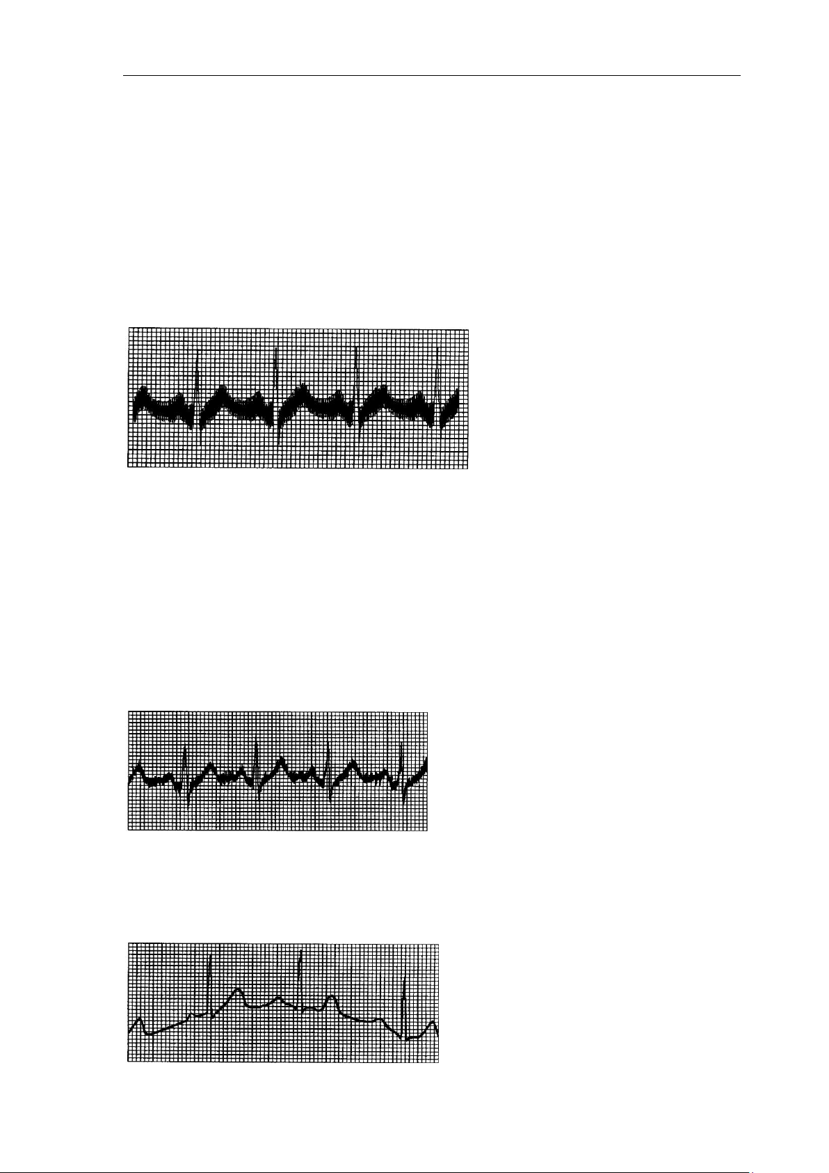
14.2 AC interference
① Is the ECG device ground cable proper?
② Is the electrode and leads’ ground cable proper?
③ Is the electrode and skin covered with enough Gel?
④ Is the metal bed grounding proper?
⑤ Does the patient touch the wall or metal sickbed?
⑥ Does other people touch the patient?
⑦ Whether there is powerful electric device working beside ECG device? For example: X
radial device or B-Ultrasound devices.
14.3 EMG interference
① Whether the patient room is comfortable.
② Is the patient nervous?
③ Is the sickbed too narrow?
14.4 Baseline drift
Page 24
User Manual
22
① Is the installation of the electrode instability?
② Is the connection between leads and electrodes credibility?
③ Check the cleaning of electrode and patient skin. Is the electrode and skin covered with
enough Gel?
④ Does it cause by the patients' moving or breathing?
⑤ Is the connection between lead and electrode proper?
Please use filter if still having above-mentioned interference.
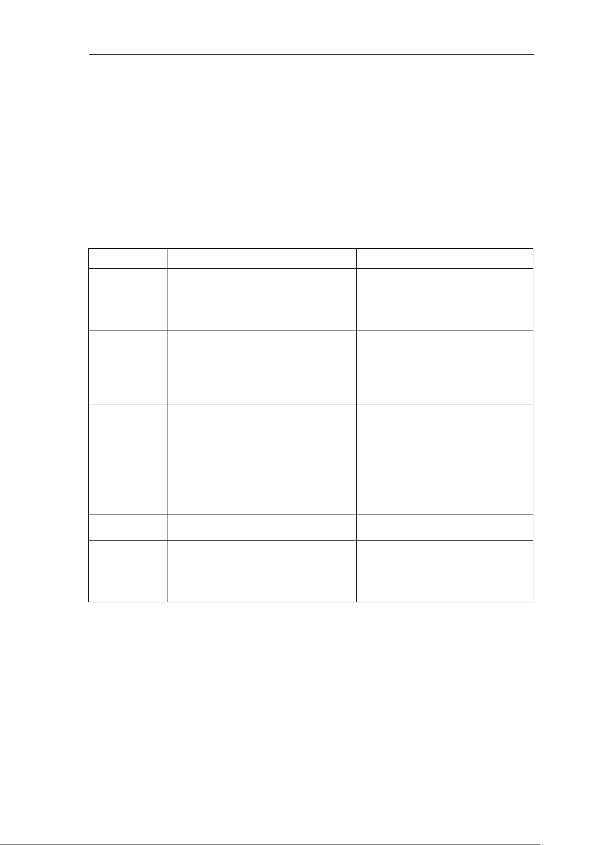
14.5 Troubleshooting List
Phenomenon
Reason
Resolve method
Disturbance too
big, the
waveform is in
disorder
1.Whether the ground cable proper.
2.The connection of leads is not stable.
3.Whether there is disturbance from
alternating current.
4.Patient is nervous
1.Please check the lead, ground
cable and power supply.
2.Please dispose the patient in
proper state.
Baseline is
rough
1.Disturbance from alternating current is
too fierce.
2.Patient is nervous and the disturbance
of EMG too strong
1.Change a comfortable
environment for patient
2.If the sickbed is metal, please
change it.
3.The power line and lead is not
parallel or too close.
Wave form is
not regular, with
too great wave
or beeline
1.The conductivity of electrode is not
well.
2.Power of battery is used up
3.Contact between electrode and skin is
not proper.
4.The plug between lead and main unit
is not tight.
5.The contact between lead and
electrode is not proper.
1.Use alcohol of high quality.
2.Clean the electrode and patient’s
skin where touch the electrode.
3.Charge the battery.
4. Keep the electrode reed clamping.
Baseline drift
1.Power of battery is used up.
2.Patient is moving.
1.Charge the battery.
2.Keep patient hold still.
Waveform is not
clear.
1.The printer head is dirty.
2.The paper is not right.
1.Clean the printer head with alcohol
when the power is off, use the printer
head after the alcohol is volatile.
2.Use the appointed thermal print
paper.
Page 25

User Manual
23
Chapter 15 Maintenance Transportation And Preservation
15.1 Customer is not permitted to open the instrument, in archive of any electronic shock. Any
maintenance or update should execute by the trained and authorized professionals from our
company .The maintenance should be done with the original accessories from our company.
15.2 Please pull out the power supply plug when power off. If the device out of use for long time,
please put the device in a shady cool dry place, and the device should be charged once every
three months.
Page 26
User Manual
24
Appendix
Guidance and manufacture’s declaration – electromagnetic emissions-
for all EQUIPMENT and SYSTEMS
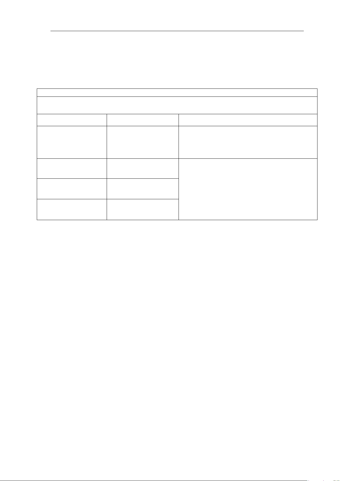
Guidance and manufacture’s declaration – electromagnetic emission
The ECG100G ECG is intended for use in the electromagnetic environment specified below. The customer of the user
of the ECG100G ECG should assure that it is used in such and environment.
Emission test
Compliance
Electromagnetic environment – guidance
RF emissions
CISPR 11
Group 1
The ECG100G ECG uses RF energy only for its
internal function. Therefore, its RF emissions are
very low and are not likely to cause any
interference in nearby electronic equipment.
RF emission
CISPR 11
Class A
The ECG100G ECG is suitable for use in all
establishments, other than domestic
establishments and those directly connected to
the public low-voltage power supply network that
supplies buildings used for domestic purposes.
Harmonic emissions
IEC 61000-3-2
Class A
Voltage fluctuations/
flicker emissions
IEC 61000-3-3
Complies
Page 27

User Manual
25
Guidance and manufacture’s declaration – electromagnetic immunity –
for all EQUIPMENT and SYSTEMS
Guidance and manufacture’s declaration – electromagnetic immunity
The ECG100G ECG is intended for use in the electromagnetic environment specified below. The customer or the user of
ECG100G ECG should assure that it is used in such an environment.
Immunity test
IEC 60601 test level
Compliance level
Electromagnetic
environment - guidance
Electrostatic
discharge (ESD)
IEC 61000-4-2
6 kV contact
8 kV air
6 kV contact
8 kV air
Floors should be wood,
concrete or ceramic tile. If floor
are covered with synthetic
material, the relative humidity
should be at least 30%.
Electrical fast
transient/burst
IEC 61000-4-4
2 kV for power supply
lines
1 kV for signal lines
2 kV for power supply
lines
1 kV for signal lines
Mains power quality should be
that of a typical commercial or
hospital environment.
Surge
IEC 61000-4-5
1 kV differential mode
2 kV common mode
1 kV differential mode
2 kV common mode
Mains power quality should be
that of a typical commercial or
hospital environment.
Voltage dips, short
interruptions and
voltage variations
on power supply
input lines
IEC 61000-4-11
<5% UT
(>95% dip in UT)
for 0.5 cycle
40% UT
(60% dip in UT)
for 5 cycles
70% UT
(30% dip in UT)
for 25 cycles
<5% UT
(>95% dip in UT)
for 5 sec
<5% UT
(>95% dip in UT)
for 0.5 cycle
40% UT
(60% dip in UT)
for 5 cycles
70% UT
(30% dip in UT)
for 25 cycles
<5% UT
(>95% dip in UT)
for 5 sec
Mains power quality should be
that of a typical commercial or
hospital environment. If the
user of the ECG100G ECG
requires continued operation
during power mains dip &
interruptions, it is
recommended that the
ECG100G ECG be powered
from an uninterruptible power
supply or a battery.
Power frequency
(50/60Hz)
magnetic field
IEC61000-4-8
3A/m
3A/m
Power frequency magnetic
fields Should be at levels
characteristic of a typical
location in a typical commercial
or hospital environment.
NOTE UT is the a.c. mains voltage prior to application of the test level.
Page 28
User Manual
26
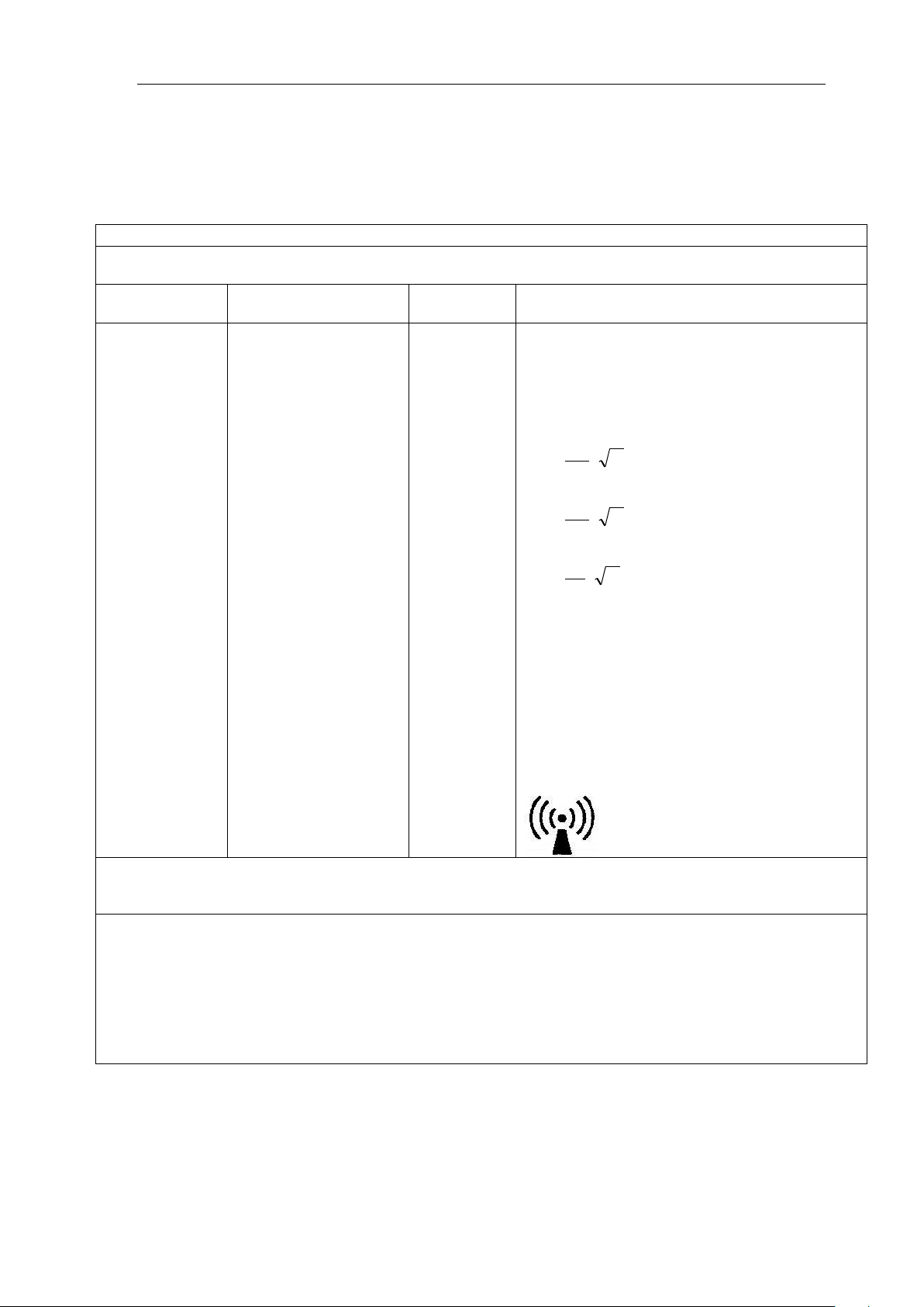
Guidance and manufacture’s declaration – electromagnetic immunity –
for EQUIPMENT and SYSTEMS that are not LIFE-SUPPORTING
Guidance and manufacture’s declaration – electromagnetic immunity
The ECG100G ECG is intended for use in the electromagnetic environment specified below. The customer or the user of
ECG100G ECG should assure that it is used in such an environment.
Immunity test
IEC 60601 test level
Complianc
e level
Electromagnetic environment - guidance
Conducted RF
IEC 61000-4-6
Radiated RF
IEC 61000-4-3
3 V
rms
150 kHz to 80 MHz
3 V/m
80 MHz to 2.5 GHz
3 V
rms
3 V/m
Portable and mobile RF communications equipment
should be used no closer to any part of the ECG100G
ECG, including cables, than the recommended
separation distance calculated from the equation
applicable to the frequency of the transmitter.
Recommended separation distance
P
V
d
1
5.3
P
E
d
1
5.3
80 MHz to 800 MHz
P
E
d
1
7
800 MHz to 2.5 GHz
Where P is the maximum output power rating of the
transmitter in watts (W) according to the transmitter
manufacturer and d is the recommended separation
distance in metres (m).
Field strengths from fixed RF transmitters, as
determined by an electromagnetic site survey,a should
be less than the compliance level in each frequency
range.b
Interference may occur in the vicinity of equipment
marked with the following symbol:
NOTE 1 At 80 MHz and 800 MHz, the higher frequency range applies.
NOTE 2 These guidelines may not apply in all situations. Electromagnetic propagation is affected by absorption and
reflection from structures, objects and people.
a
Field strengths from fixed transmitters, such as base stations for radio (cellular/cordless) telephones and land mobile
radios, amateur radio, AM and FM radio broadcast and TV broadcast cannot be predicted theoretically with accuracy.
To assess the electromagnetic environment due to fixed RF transmitters, an electromagnetic site survey should be
considered. If the measured field strength in the location in which the ECG100G ECG is used exceeds the applicable
RF compliance level above, the ECG100G ECG should be observed to verify normal operation. If abnormal
performance is observed, additional measures may be necessary, such as reorienting or relocating the ECG100G
ECG.
b
Over the frequency range 150 kHz to 80 MHz, field strengths should be less than 3 V/m.
Page 29
User Manual
27
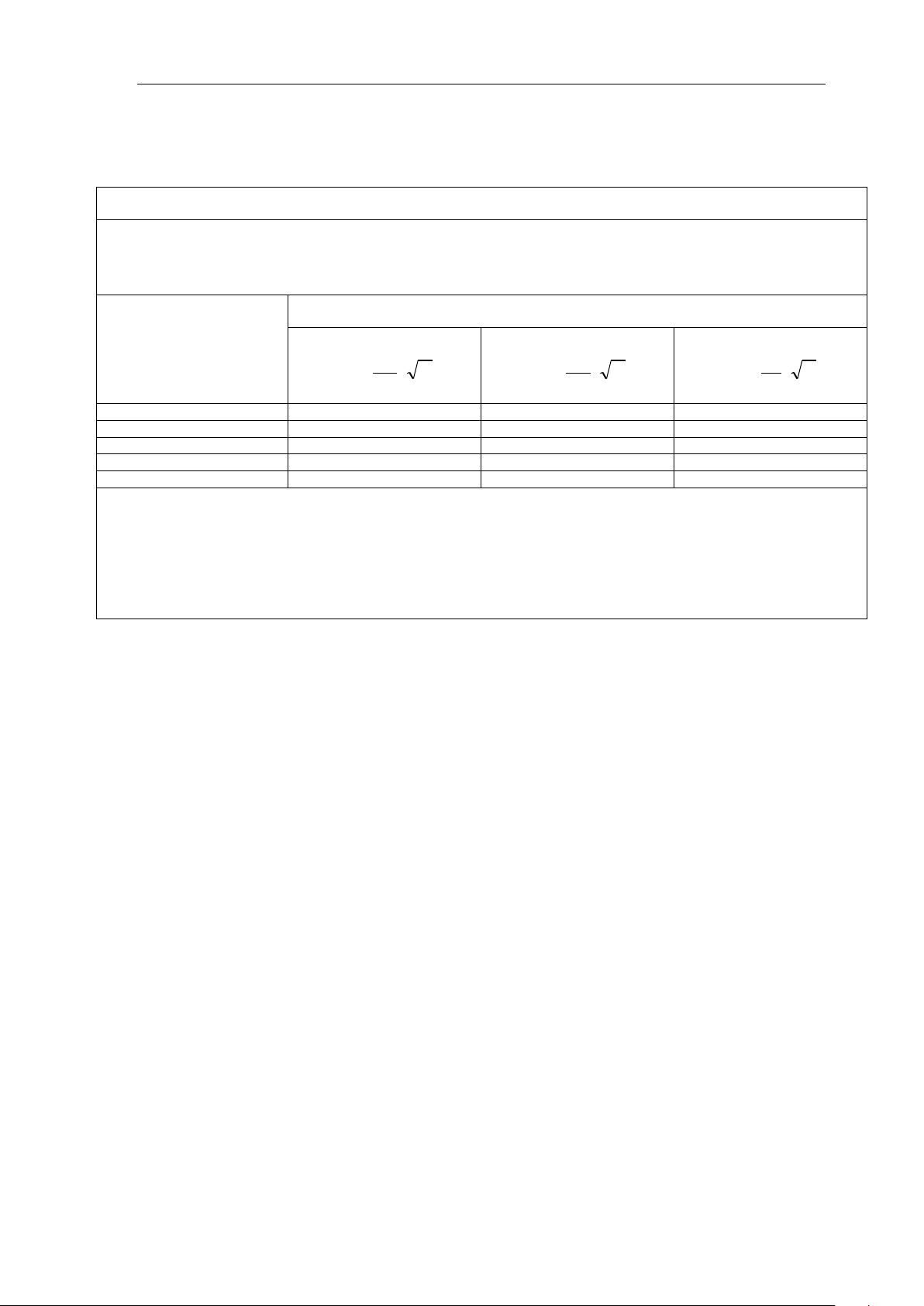
Recommended separation distances between portable and mobile
RF communications equipment and the EQUIPMENT or SYSTEM –
for EQUIPMENT or SYSTEM that are not LIFE-SUPPORTING
Recommended separation distances between
portable and mobile RF communications equipment and the ECG100G ECG
The ECG100G ECG is intended for use in an electromagnetic environment in which radiated RF disturbances are
controlled. The customer or the user of the ECG100G ECG can help prevent electromagnetic interference by maintaining a
minimum distance between portable and mobile RF communications equipment (transmitters) and the ECG100G ECG as
recommended below, according to the maximum output power of the communications equipment.
Rated maximum output
power of transmitter
(W)
Separation distance according to frequency of transmitter
(m)
150 kHz to 80 MHz
P
V
d
1
5.3
80 MHz to 800 MHz
P
E
d
1
5.3
800 MHz to 2.5 GHz
P
E
d
1
7
0.01
0.117
0.117
0.233
0.1
0.369
0.369
0.738
1
1.17
1.17
2.333
10
3.69
3.69
7.379
100
11.7
11.7
23.33
For transmitters rated at a maximum output power not listed above, the recommended separation distance d in metres (m)
can be estimated using the equation applicable to the frequency of the transmitter, where P is the maximum output power
rating of the transmitter in watts (W) according to the transmitter manufacturer.
NOTE 1 At 80 MHz and 800 MHz, the separation distance for the higher frequency range applies.
NOTE 2 These guidelines may not apply in all situations. Electromagnetic propagation is affected by absorption and
reflection from structures, objects and people.
Page 30
User Manual
28
Disposal: The product must not be disposed of along with other domestic waste. The users
must dispose of this equipment by bringing it to a specific recycling point for electric and
electronic equipment. For further information on recycling points contact the local
authorities, the local recycling center or the shop where the product was purchased. If the
equipment is not disposed of correctly, fines or penalties may be applied in accordance with
the national legislation and regulations.
0123
CONTEC MEDICAL SYSTEMS CO., LTD
No. 112 Qinhuang West Street, Economic & Technical Development Zone,
Qinhuangdao, Hebei Province, PEOPLE'S REPUBLIC OF CHINA
Shanghai International Holding Corp. GmbH (Europe)
Eiffestrasse 80, 20537, Hamburg, Germany
Page 31

User Manual
29
Explanations of symbols on unit
Symbol for "applied parts" (the electrodes are type CF applied
parts).
Symbol for "environment protection" - waste electrical products
should not be disposed of with household waste. Please recycle
where facilities exist. Check with your local Authority or retailer for
recycling advice.
Symbol for "manufacturer".
Symbol for "complies with MDD93/42/EEC requirements".
Symbol for "date of manufacture".
Symbol for "European representative".
Symbol for "serial number".
Rev.1.11.17
0123
 Loading...