

Page 1

PC-HELPER
PCI Bus Expansion Adapter
for Low Profile PCI PC-Slot
EAD(LPCI)SF
User’s Manual
CONTEC CO.,LTD.
Page 2
Check Your Package
Thank you for purchasing the CONTEC product.
The product consists of the items listed below.
Check, with the following list, t hat your packa ge is complete. If yo u discover dam aged or missi ng items,
contact your retailer.
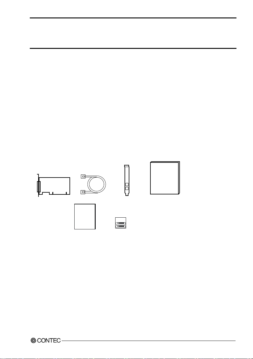
Product Configuration List
- Expansion adapter board [BUS-PC(LPCI)SF] …1
- Connection cable
[STP-category, 5e straight cables (12m)] …2
- User’s Manual (this booklet) …1
- Bracket for the PCI …1
- Warranty Certificate …1
- Serial number label …1
User's Manual
Expansion adapter board Connection cable
Warr ant y
Certificate
Warranty Certificate
EAD(LPCI)SF
Bracket for the PCI
XXXXXXXXXXXXX
XXXXXXXXXXXXX
Serial number label
User's Manual
i
Page 3

Copyright
Copyright 2012 CONTEC CO., LTD. ALL RIGHTS RESERVED.
No part of this document may be copied or reproduced in any form by any means without prior written
consent of CONTEC CO., LTD.
CONTEC CO., LTD. makes no commitment to update or keep c urre nt t he i n formation contained in this
document. The information in this document is subject to change without notice.
All relevant issues hav e be en consid e red in th e prep ar atio n of th is do cu men t. Sh ould yo u no tic e an
omission or any questionable item in this document, please feel free to notify CONTEC CO., LTD.
Regardless of the foregoing statement, CONTEC assumes no responsibility for any errors that may
appear in this document or for results obtained by the user as a result of using this product.
Trademarks
MS, Microsoft, Windows and Windows NT are trademarks of Microsoft Corporation. Other brand and
product names are trademarks of their respective holder.
EAD(LPCI)SF
ii
Page 4

Table of Contents
Check Your Packag e............................................................................................................................i
Copyright ............................................................................................................................................ii
Trademarks ......................................................................................................................................... ii
Table of Con tents...............................................................................................................................iii
1. BEFORE USING THE PRODUCT 1
About the A d a p ter............................................................................................................................... 1
Features........................................................................................................................................ 1
Expansion chassi s (O p tio n ) ......................................................................................................... 1
Connection cab l e (Op t io n ) ........................................................................................................... 1
Combinations of Ex p ans io n Ad ap t ers and Expansion Chassis................................................... 2
Restrictions .................................................................................................................................. 3
Customer Supp o rt ............................................................................................................................... 4
Web Site....................................................................................................................................... 4
Limited One Ye a r W ar ra nt y ............................................................................................................... 4
How to Obtain Serv i ce ....................................................................................................................... 4
Liability............................................................................................................................................... 4
Safety Precau t io ns .............................................................................................................................. 5
Safety Infor mat i o n .......................................................................................................................5
Handling Pre ca u tio ns................................................................................................................... 6
Environment................................................................................................................................. 7
Inspection..................................................................................................................................... 7
Storage ......................................................................................................................................... 7
Disposal ....................................................................................................................................... 7
2. SETUP 9
What is Setup? .................................................................................................................................... 9
Step 1 Preparation............................................................................................................................... 9
Items to be prep a r ed .................................................................................................................. 10
Names of majo r p ar ts................................................................................................................. 11
Step 2 Installi ng t he E xp ans i on B o ard ............................................................................................. 11
Step 3 Installing th e ex p ansion adapte r board.................................................................................. 12
Step 4 Connecting the Cab le ............................................................................................................13
Connecting the con nec tio n c ab le to the B US -P C (L PC I) SF...................................................... 13
Connecting the con nec tio n c ab le to the Expansion Chassis ..................................................... 13
Plugging th e Power Cable ......................................................................................................... 14
EAD(LPCI)SF
iii
Page 5

Step 5 Setup an d Ch eck ....................................................................................................................1 5
Starting the s yst e m..................................................................................................................... 15
Setting up th e h ar dw a re in Win d o w s......................................................................................... 16
Setup the “Add N e w Ha rd w a re W i za rd ”................................................................................... 16
Checking the hardware in W i n dows.......................................................................................... 20
Setup Troubl esh o ot in g...................................................................................................................... 22
Symptoms and A cti on s .............................................................................................................. 22
If your proble m c an n ot b e reso lv ed........................................................................................... 23
3. ABOUT HARDWARE 25
Hardware spe cification .....................................................................................................................25
BUS-PC(LPCI) SF...................................................................................................................... 25
Restrictions and N ot es ......................................................................................................................26
Replacing the B ra ck e t................................................................................................................ 26
EAD(LPCI)SF
iv
Page 6

1. Before Using the Product
1. Before Using the Product
This chapter provides information you should know before using the product.
About the Adapter
The EAD(LPCI)SF is an expansion adapter that connects the optional expansion chassis [ECH(PCI)SF]
to a PC to extend a PCI bus expansion slot in the PC, thereby providing additional PCI bus expansion
slots. The expansion adapter can connect the expansion chassis to the PC over a distance of up to 12m.
Features
- Using high-speed serial transfer (2.5 Gbps), capable of extending the PCI bus to up to 12m.
- PCI-bus compatible, eliminating the need for changing PCI bus board software.
- Using a, noise-immune, STP-category, 5e cable easy to wire and install.
- Capable of expand the PCI bus (5V/32-bit, 33 MHz) from a single PCI bus slot in th e PC.
- Expansion chassis free of choice according to the number of PCI bus slots and the board size required.
- Power supply controllable in respo ns e to the turn ing on/off of th e P C’s pow er supp ly.
- Supporting both of Low Profile and standard PCI slots (exchangeable with the bundled bracket).
Expansion chassis (Option)
PCI Bus Expansion Chassis
PCI Bus Expansion Chassis (Short x 2Slots) : ECH(PCI)SF-H2B
PCI Bus Expansion Chassis (Long x 2Slots) : ECH(PCI)SF-F2B
PCI Bus Expansion Chassis (Short x 4Slots) : ECH(PCI)SF-H4B
PCI Bus Expansion Chassis (Long x 4Slots) : ECH(PCI)SF-F4B
PCI Bus Expansion Chassis (Short x 4Slots) : ECH(PCI)SF-H4A
PCI Bus Expansion Chassis (Short x 7Slots) : ECH(PCI)SF-H7A
PCI Bus Expansion Chassis (Long x 7Slots) : ECH(PCI)SF-F7A
PCI Bus Expansion Chassis (Short x 13Slots) : ECH(PCI)SF-H13A
PCI Bus Expansion Chassis (Long x 13Slots) : ECH(PCI)SF-F13A
Check the CONTEC’s Web site for more information on these expansion chassis.
Connection cable (Option)
Connection cables (12-meter, STP-category, 5e straight cables) are bundled with this product. The
following options can also be available:
UTP-category, 5e straight cables (3m): TP-03 *1*2
UTP-category, 5e straight cables (5m): TP-05 *1*2
UTP-category, 5e straight cables (10m): TP-10 *1*2
*1: A pair of cables are required for connection.
*2: When used in an environment susceptible to extraneous noise, UTP cables may cause link
connection. It is advisable to use STP cables available on the market.
EAD(LPCI)SF
1
Page 7
1. Before Using the Product
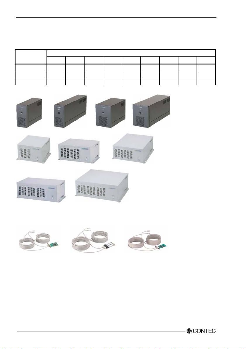
Combinations of Expansion Adapters and Expansion Chassis
The expansion adapters and expansion chassis can be used in the following combinations:
Expansion
adapter
EAD(CB)SF Ο Ο Ο Ο Ο x x x x
EAD(LPCI)SF Ο Ο Ο Ο Ο Ο Ο Ο Ο
EAD-SF-LPE
-H2B -F2B -H4B -F4B -H4A -H7A -F7A -H13A -F13A
○ ○ ○ ○ ○ ○ ○ ○ ○
Expansion chassis
Expansion chassis ECH(PCI)SF
ECH(PCI)SF-H2B ECH(PCI)SF-F2B ECH(PCI)SF-H4B ECH(PCI)SF-F4B
ECH(PCI)SF-H4A ECH(PCI)SF-H7A ECH(PCI)SF-F7A
ECH(PCI)SF-H13A ECH(PCI)SF-F13A
Expansion adapter
EAD(LPCI)SF EAD(CB)SF EAD-SF-LPE
EAD(LPCI)SF
2
Page 8

1. Before Using the Product
Restrictions
EAD(LPCI)SF has restrictions on the types of PCs and boards that can be used.
Be sure to check the following restrictions before use.
< Restrictions of PC >
EAD(LPCI)SF uses the switch fabric to extend the bus.
The PCI boards plugged in PCI slots in the EAD(LPCI)SF are recognized if the switch fabric is
recognized as the PCI-to-PCI bridge by the BIOS in the PC used. Ask the PC vendor for whether the
BIOS recognizes the PCI-to-PCI bridge.
< Restrictions on transfer rate >
When the expansion chassis accommodates a board that performs high-speed transfer such as bus
mastering, the overall transfer rate may be lower than that of PCI bus slots in the main unit of a desktop
PC.
This is caused by bus extension by the PCI-to-PCI Bridge.
The transfer rate may vary with the system configuration and the type of the PC.
< Restrictions of PCI board >
None of the following types of boards can be used in any expansion slot in the expansion chassis.
- Video display board (VGA board)
- Board to connect a PCI bus expansion unit
- Board explicitly stated not to be used with the PCI-to-PCI Bridge
Some boards, even PCI-compliant ones, may not work depending on their specifications.
EAD(LPCI)SF
3
Page 9

1. Before Using the Product
Customer Support
CONTEC provides the following s upport services fo r you to use CONTEC products more efficiently and
comfortably.
Web Site
Japanese http://www.contec.co.jp/
English http://www.contec.com/
Chinese http://www.contec.com.cn/
Latest product information
CONTEC provides up-to-date information on products.
CONTEC also provides product manuals and various technical documents in the PDF.
Free download
You can download updated driver software a nd diff erenti al files as we ll as sample pr ograms available i n
several languages.
Note! For product information
Contact your retailer if you have any technical question about a CONTEC product or need its price,
delivery time, or estimate information.
Limited One Year Warranty
CONTEC products are warranted by CONTEC CO., LTD. to be free from defects in material and
workmanship for up to one year from the date of purchase by the original purchaser.
Repair will be free of char ge only w hen thi s device is ret urned fr eight pr epaid with a c opy of t he origi nal
invoice and a Return Merchandise Authorization to the distributor or the CONTEC group office, from
which it was purchased.
This warranty is not applicable for scratches or normal wear, but only for the electronic circuitry and
original products. The warranty is not applicable if the device has been tampered with or damaged
through abuse, mistreatment, neglect, or unreasonable use, or if the original invoice is not included, in
which case repairs will be considered beyond the warranty policy.
How to Obtain Service
For replacement or repair, return the device freight prepaid, with a copy of the original invoice. Please
obtain a Return Merchandise Authorization number (RMA) from the CONTEC group office where you
purchased before returning any product.
* No product will be accepted by CONTEC group without the RMA number.
Liability
The obligation of the warrantor is solely to repair or replace the product. In no event will the warrantor
be liable for any incidental or consequential damages due to s uch defec t or consequence s that arise from
inexperienced usage, misuse, or malfunction of this device.
EAD(LPCI)SF
4
Page 10
1. Before Using the Product
Safety Precautions
Understand the following definitions and precautions to use the product safely.
Safety Information
This document provides safety information u sing the foll owing sym bols to prevent a ccidents res ulting in
injury or death and the destruc tion of equi pment and res ources. Under stand the mean ings of these la bels
to operate the equipment safely.
DANGER
WAR NI NG
CAUTION
DANGER indicates an imminently hazardous situation which, if not avoided, will
result in death or serious injury.
WARNING indicates a potentially hazardous situation which, if not avoided, could
result in death or serious injury.
CAUTION indicates a potentially hazardous situation which, if not avoided, may
result in minor or moderate injury or in property damage.
EAD(LPCI)SF
5
Page 11

1. Before Using the Product
Handling Precautions
DANGER
Do not use the product where it is exposed to flamm able or corr osive ga s. Doi ng so m ay result in an
explosion, fire, electric shock, or failure.
CAUTION
- The Board must be plugged into an expansion slot conforming to the PCI Bus Standard on a PC.
- Do not impact or bend the board.
Doing so may result in a malfunction, overheating, fault, or damage.
- Do not plug or unplug any board into or from the expansion slot with the PC or
expansion chassis powered. Doing so may result in a malfunction, overheating, fault.
Be sure to turn off the PC or expansion chassis and unplug their power cables before plugging or
unplugging any expansion board.
- Do not plug or unplug the cable interconnecting the PC and expansion chassis with the PC or
expansion chassis powered.
- Do not connect any signal other than specified to the on-board connector.
Doing so may result in a malfunction, overheating, fault, or damage.
- If a specific expansion slot is recommended for a board, plug the board into that slot.
Doing so may result in a malfunction, overheating, fault, or damage.
- When plugging or unplugging the power cable, be sure to hold it by the plug itself.
- Do not use or store the board where it is exposed to any chemical either directly or as vapor in the
air.
- The specifications of this product are subject to change without notice for enhancement or quality
improvement.
Even when using the product continuously, be sure to read the manual and understand the contents.
- Do not modify this product.
CONTEC will bear no responsibility for any problems, etc., resulting from modifying the product.
- Regardless of the foregoing statements, CONTEC is not liable for any damages whatsoever
(including damages for loss of business profits) arising out of the use of or inability to use this
CONTEC product or the information contained herein.
EAD(LPCI)SF
6
Page 12

1. Before Using the Product
Environment
Use this product in the following environment. If used in an unauthorized environment, the board may
overheat, malfunction, or cause a failure.
Operating temperature
0 - 50°C
Humidity
10 - 90%RH (No condensation)
Corrosive gases
None
Floating dust particles
Not to be excessive
Inspection
Inspect the product periodically as follows to use it safely.
- Check that the bus connector
of the board and its cable have
been plugged correctly.
- Check that the board has
no dust or foreign matter adhering.
BUS-PC(LPCI)SF
JP1
- The gold-plated leads of the bus connector
have no stain or corrosion.
Storage
When storing this product, keep it in its original packing fo rm.
(1) Put the board in the storage bag.
(2) Wrap it in the packing material, then put it in the box.
(3) Store the package at room temperature at a place free from direct sunlight, moisture, shock,
vibration, magnetism, and static electricity.
Disposal
When disposing of the product, follow the disposal procedures stipulated under the relevant laws and
municipal ordinances.
EAD(LPCI)SF
7
Page 13

1. Before Using the Product
EAD(LPCI)SF
8
Page 14

2. Setup
2. Setup
This chapter explains how to set up the board.
Refer to the user’s manual for the expansion chassis ECH(PCI)SF-H2B/F2B/H4B/F4B,
ECH(PCI)SF-H4A/F7A/F13A as required.
What is Setup?
Setup means a series of steps to take before the product can be used.
Taking the following steps in this chapter sets up the EAD(LPCI)SF.
Step 1 Preparation
Step 2 Installing the Expansion Board
Step 3 Installing the expansion adapter board
Step 4 Connecting the Cable
Step 5 Setup and Check
If setup fails to be performed correctly, refer to “Setup Troubleshooting”.
Step 1 Preparation
Configuration image
The photo is of the EAD(LPCI)SF+ECH(PCI)SF-H4A.
Figure 2.1. Configuration image
EAD(LPCI)SF
CONTEC
9
Page 15

2. Setup
Items to be prepared
- PC
- Expansion adapter (This product)
(The expansion adapter consists of a board to be plugged on a PC and connection cables.)
Expansion adapter board [BUS-PC(LPCI)SF] …(a),
Connection Cable …(b)
(The connection cables can be substituted for by UTP- or STP-category 5e straight cables of up to
12m in length.)
- Expansion chassis
Chassis …(c ), Pow er ca ble
- PCI board to be installed
- INF file (Required only for Device Manager to detect the expansion adapter correctly)
Even with the INF file not used, the expansion adapter works normally but is not displayed correctly in
Device Manager.
Download the INF file from the CONTEC’s Web site.
(c)
(b)
(a)
The photo is of the EAD(LPCI)SF+ECH(PCI)SF-H4A but the check points are the same as with the
ECH(PCI)SF-H2B/F2B/H4B/F4B/F7A/F13A.
CAUTION
When used in an environment susceptible to extraneous noise, UTP cables may cause link
connection. It is advisable to use STP cables available on the market.
EAD(LPCI)SF
10
Page 16

2. Setup
Names of major parts
BUS-PC(LPCI)SF
- Interface connector
(CN1, CN2)
BUS-PC(LPCI)SF
RX
- Power supply voltage
setting jumper for
PCI bus slot
JP1
123
TX
- LINK LED for RX
- LINK LED for TX
JP1
Figure 2.2. Names of major parts < BUS-PC(LPCI)SF >
Power supply voltage for PCI bus slot
Some PCI bus slots in your PC may supply power only at 3.3V but not at 5V. In that case, the expansion
adapter does not work with its f actory settings.
Move the JP1’s jumper plug from the 2-3 position to the 1-2 position.
For power supply at 5V
123
JP1
(Factory setting)
For power supply not at 5V
123
JP1
Figure 2.3. Power supply voltage setting for PCI bus slot
LINK LED
The LINK LEDs show whether the switch fabric device is working normally.
Both of the TX and RX LEDs remain on when the device is working nor mally. If they are b linking or off,
see "Setup Troubleshooting.
Step 2 Installing the Expansion Board
Refer to the user’s manual for the expansion chassis to install the expansion board on the expansion
chassis.
EAD(LPCI)SF
11
Page 17

2. Setup
Step 3 Installing the expansion adapter board
(1) Bef ore plugging the board, shut down the syste m, unplug the power cable of you r PC fro m a wall
outlet.
(2) Remove the cover from the PC so that the board can be mounted.
(3) Plug the board into an expansion slot.
(4) Attach the board bracket to the PC with a screw.
(5) Put the cover back into place.
The photo is of the BUS-PC(LPCI)SF
Applicable PCI bus slots
PCI bus slots used in PCs have keys to prevent 5V and 3.3V PCI bus boards from being accidentally
plugged into wrong bus slots. This board can be plugged into both of the 5V and 3.3V PCI bus slots.
<PCI bus slot> <PCI bus board>
5-V PCI bus slot
3.3-V PCI bus slot
3.3V key
CAUTION
5V key
A :
Slit for 5-V PCI bus slot
B :
Slit for 3.3-V PCI bus slot
AB
- Do not touch the board's metal plated terminals (edge connector) with your hands.
Otherwise, the board may malfunction, overheat, or cause a failure.
If the terminals are touched by someone's hands, clean the terminals with industrial alcohol.
- Do not install or remove the board to or from the expansion slot with the PC or expansion chassis
powered.
Otherwise, the board may malfunction, overheat, or cause a failure.
Be sure to turn off the PC.
- Make sure that your PC or expansion chassis can supply ample power to all the boards installed.
Insufficiently energized boards could malfunction, overheat, or cause a failure.
EAD(LPCI)SF
12
Page 18

2. Setup
Step 4 Connecting the Cable
Connecting the connection cable to the BUS-PC(LPCI)SF
Connect the connection cable to the expansion adapter board [BUS-PC(LPCI)SF] as shown in Figure 2.4
below.
Make sure that the connection cable connectors are locked.
CAUTION
- Do not plug or unplug connector with the PC powered. Doing so may result in a malfunction.
- When used in an environment susceptible to extraneous noise, UTP cables may cause link
connection. It is advisable to use STP cables available on the market.
- The PC may malfunction if link disconnection occurs with the LINK LED blinking or off.
Figure 2.4. Connecting the connection cable to the BUS-PC(LPCI)SF
Connection Cable
Board
Connecting the connection cable to the Expansion Chassis
Refer to the user’s manual for the expansion chassis ECH(PCI)SF-H2B/F2B/H4B/F4B,
ECH(PCI)SF-H4A/H7A/F7A/H13A/F13A to connect its connection cable to the expansion chassis.
Connect the ECH(PCI)SF-H2B/F2B/H4B/F4B and ECH(PCI)SF-H4A/H7A/F7A/H13A/F13A to the
expansion adapter EAD(LPCI)SF installed on the PC as shown below.
EAD(LPCI)SF/EAD(CB)SF ECH(PCI)SF-H2B/F2B/H4B/F4B
TX
RX
Figure 2.5. Connecting the expansion bus adapter
EAD(LPCI)SF
ECH(PCI)SF-H4A/H7A/F7A/H13A/F13A
TX
RX
13
Page 19

2. Setup
LINK LED
The LINK LEDs show whether the switch fabric device is working normally.
Both of the TX and RX LEDs remain on when the device is working nor mally. If they are b linking or off,
see “Setup Troubleshooting”.
CAUTION
The PC may malfunction if link disconnection occurs with the LINK LED blinking or off.
Plugging the Power Cabl e
(1) Connect the power cable to the expansion chassis.
CAUTION
Do not plug or unplug any board into or from the expansion slot with the PC or
expansion chassis powered. Doing so may result in a malfunction, overheating, fault.
Be sure to turn off the PC or expansion chassis and unplug their power cables before plugging or
unplugging any expansion board.
EAD(LPCI)SF
14
Page 20

2. Setup
Step 5 Setup and Check
Starting the system
The expansion chassis is turned on and off in sync with the PC ’s power supp ly.
Turning on the system
(1) Plug the power plug of the expan s ion ch a ssis into a wa ll ou tle t.
You do not need to press the POWER switch on the front panel (*1).
(2) The po wer supply of a PC is turned ON.
(3) The expansion chassis is turned on in synchronization with the PC’s power supply.
(4) Make sure that the POWER LED on the expansion chassis and the LINK LED on the RJ-45
connector is on.
Turning off the s ystem
(1) The po wer supply of a PC is turned OFF.
(2) The expansion chassis is turned off in synchronization with the PC’s power supply.
*1 Pressing the POWER switch on the front panel of the expansio n ch assis turns o n th e
expansion chassis or puts it to sleep.
Use the switch, for example, to turn on only the expansion chassis.
CAUTION
- Do not turn on or off the expansion chassis with the PC main unit powered.
Doing so cancels the detection of the bus adapter. When turning the expansion chassis on back,
restart the PC main unit.
- Do not plug or unplug any board into or from the expansion slot with the PC or
expansion chassis powered. Doing so may result in a malfunction, overheating, fault.
Be sure to turn off the PC or expansion chassis and unplug their power cables before plugging or
unplugging any expansion board.
- If you turn on the PC after turning it off, keep a time interval of at least 10 seconds in between. If the
power OFF-to-ON interval is too short, the expansion chassis may fail to be turned on.
EAD(LPCI)SF
15
Page 21

2. Setup
(
Setting up the hardware in Windows
Upon startup of Windows, the switch fabric devices used by the expansion adapter and the expansion
chassis are detected as a PCI-to-PCI Bridge and Other PCI Bridge Device in sequence. PCI-to-PCI
Bridges are recognized automatically by a Windows standard driver but Other PCI Bridge Devices are
not supported by any Window s standar d driver. T herefore the Other PCI Bridge Device re quires an INF
file before it can be recognized correctly.
(Note that the expansion chassis works normally even without the INF file.)
For setting up and checking the boards used on the expansion chassis, refer to their respective manuals.
Setup the “Add New Hardware Wizard”
When the INF file is not used
(1) The “Add New Hardware Wizard” will be started.
Select the “Install the software automatically [Recommended]” and then click on the “N
* The name of the board you
have just added is
displayed.
LPCI)SF
- EAD
ext” button.
EAD(LPCI)SF
16
Page 22

2. Setup
(2) INF file is not here, so the following screen is displayed.
Select the “No, do not connect to the Internet now” and then click on the “N
(3) Click on the “Finish” button and then complete the Hardware Wizard.
ext” button.
EAD(LPCI)SF
17
Page 23

2. Setup
(
When the INF file is us ed
(1) The “Add New Hardware Wizard” will be started.
Select “Install from a list or s
(2) Specify the location of the file downloaded from the CONTEC's web site to register the board.
pecific location (Advanced)”, then click on the [Next] button.
* The name of the board you
have just added is
displayed.
LPCI)SF
-EAD
The name of the board you
have just added is displayed.
- EAD(LPCI)SF
EAD(LPCI)SF
18
Page 24

2. Setup
CAUTION
In Windows XP, the Hardware Wizard displays the following alert dialog box when you have
located the INF file. This dialog box appears, only indicating that the releva nt dr iver has not passe d
Windows Logo testing, an d it ca n be i gnored without developing any prob lem wit h t he oper a ti on of
the board.
Here, push the “C
Now, hardware has been installed.
ontinue Anyway” button.
* The name of the PC board
you have just added is displayed.
- EAD(LPCI)SF
EAD(LPCI)SF
19
Page 25

2. Setup
Checking the hardware in Windows
You can use Device Manager to check whether the expansion adapter and expansion chassis has been
identified in Windows. Device Manager shows “PCI standard PCI-to-PCI bridge” under “System
devices”.
The expansion adapter and expansion chassis in use can be identified with the number of "PCI standard
PCI-to-PCI bridge" entries.
Two entries: ECH(PCI)SF -H2 B/F2 B /H4B / F4B/ H4 A
Three entries: ECH(PCI)SF-H7A/F7A
Five entries: ECH(PCI)SF-H13A/F13A
CAUTION
The expansion adapter EAD(LPCI)SF does not depend on the OS in use.
When the INF file is not used
If you install the expansion adapter without using the INF file, Device Manager looks as shown below.
The Other PCI Bridge Devices are not recognized normally but the expansion adapter works with no
problem.
Figure 2.6. Sample screen shot of Device Manager (When the INF file is not used)
EAD(LPCI)SF
20
Page 26

2. Setup
When the INF file is us ed
Two EAD(LPCI)SF are
displayed as the device.
Figure 2.7. Sample screen shot of Device Manager (When the INF file is used)
EAD(LPCI)SF
21
Page 27

2. Setup
Setup Troubleshooting
Please confirm followings when EAD(LPCI)SF does not work.
Symptoms and Actions
The chassis won’t be turned on.
a. Make sure that the power cable has been connected correctly.
b. Make sure that the power supplies of the PC and expansion chassis are on.
c. Make sure that you have followed the procedure in Chapter 2.
d. Even though the chassis is still not turned on, check whether it is turned on with no board installed.
If the chassis is turned on with no board installed, check the total current consumption by the
installed boards. The total current consumption must not exceed the power capacity of the
expansion chassis.
No PCI board on the expansion chassis is detected.
e. Make sure that the expansion adapter board [BUS-PC(LPCI)SF] has been installed correctly.
f. Make sure that the JP1 jumper on the expansion adapter board [BUS-PC(LPCI)SF] in the PC has
been set correctly.
g. Make sure that the connection cable has been installed correctly.
When connecting the connection cable to the main chassis, insert the connector until it clicks into
place.
EAD(LPCI)SF/EAD(CB)SF ECH(PCI)SF-H2B/F2B/H4B/F4B
ECH(PCI)SF-H4A/H7A/F7A/H13A/F13A
TX
RX
h. Make sure that the POWER LED on th e exp an sion ch ass is is tu rn ed on.
EAD(LPCI)SF
22
TX
RX
Page 28

2. Setup
i Make sure that the LED (LINK) built in the RJ-45 connector is on.
When used in an environment susceptible to extraneous noise, UTP cables may cause link
connection. It is advisable to use STP cables available on the market.
a
g
f
e
The photo is of the EAD(LPCI)SF+ECH(PCI)SF-H4A but the check points are the same as with the
ECH(PCI)SF-H2B/F2B/H4B/F4B/H7A/F7/H13A/F13A.
If your problem cannot be resolved
Contact your retailer.
EAD(LPCI)SF
23
Page 29

2. Setup
EAD(LPCI)SF
24
Page 30

3. About Hardware
3. About Hardware
Hardware specification
BUS-PC(LPCI)SF
Table 3.1. Specification < BUS-PC(LPCI)SF >
Item Specification
Compatible bus PCI Local Bus Specification Rev2.2 (+5V/+3.3V type)
Outside dimensions (mm) 121.69(L) x 63.41(H)
450mA *1 (JP1 pins 1 and 2 connected)
Power consumption (Max.)
Usable condition 0 - 50°C, 10 - 90%RH (No condensation)
Weight 50g
*1: Power is supplied from the PC’s main unit.
Table 3.2. Specification of the bundled cable
Item Specification
Bundled connection cable STP-category, 5e straight cables 12m x 2 cables
Weight 400g / cable
Board Dimensions
3.3VDC
5VDC
350mA *1 (JP1 pins 2 and 3 connected)
121.69(L)
63.41(H)
The standard outside dimension(L) is
the distance from the end of the board
to the outer surface of the slot cover.
[mm]
EAD(LPCI)SF
25
Page 31

3. About Hardware
Restrictions and Notes
Replacing the Bracket
This product is shipped with a Low Profile size bracket mounted. To plug the product into a standard
size slot, replace the bracket with the bundled standard size bracket. The replacing method is as follows :
Standard size brac ket
- Remove the screws and replace it
with the Standard size bracket.
Low Profile size br acket
Screws
Use a standard screwdriver to attach and detach the screws.
Figure 3.1. Replacing the Bracket
EAD(LPCI)SF
26
Page 32

EAD(LPCI)SF
User’s Manual
CONTEC CO., LTD. February 2013 Edition
3-9-31, Himesato, Nishiyodogawa-ku, Osaka 555-0025, Japan
Japanese http://www.contec.co.jp/
English http://www.contec.com/
Chinese http://www.contec.com.cn/
No part of this document may be copied or reproduced in any form by any means without prior written
consent of CONTEC CO., LTD. [02152013]
[04212004] Management No. A-46-850
[02152013_rev3] PartsNo. LYDK312
 Loading...