

Page 1

PC-HELPER
Digital I/O Board with Opto-Isolation
for PCI Express,
DIO-6464L-PE
Digital Input Board with Opto-Isolation
DI-128L-PE
Digital Output Board with Opto-Isolation
DO-128L-PE
User’s Guide
CONTEC CO.,LTD.
Page 2
Check Your Package
Thank you for purchasing the CONTEC product.
The product consists of the items listed below.
Check, with the following list, t hat your packa ge is complete. If yo u discover dam aged or missi ng items,
contact your retailer.
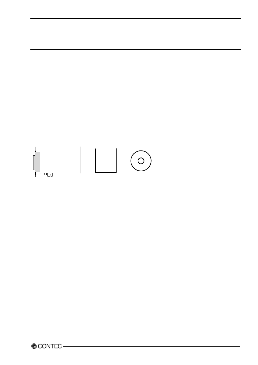
Product Configuration List
- Board (one of the followings)
[DIO-6464L-PE, DI-128L-PE or DO-128L-PE]…1
- First step guide…1
- CD-ROM *1 [API-PAC(W32)]…1
*1 The CD-ROM contains the driver software and User’s Guide (this guide)
CD-ROM
Board
First step guide
[API-PAC(W32)]
DIO-6464L-PE, DI-128L-PE, DO-128L-PE
i
Page 3

Copyright
Copyright 2006 CONTEC CO., LTD. ALL RIGHTS RESERVED.
No part of this document may be copied or reproduced in any form by any means without prior written
consent of CONTEC CO., LTD.
CONTEC CO., LTD. makes no commitment to update or keep current the information contained in this
document. The information in this document is subject to change without notice.
All relevant issues have been considered in the preparation of this document. Should you notice an
omission or any questionable item in this document, please feel free to notify CONTEC CO., LTD.
Regardless of the foregoing statement, CONTEC assumes no responsibility for any errors that may
appear in this document or for results obtained by the user as a result of using this product.
Trademarks
MS, Microsoft, Windows and Windows NT are trademarks of Microsoft Corporation. Other brand and
product names are trademarks of their respective holder.
DIO-6464L-PE, DI-128L-PE, DO-128L-PE
ii
Page 4

Table of Contents
Check Your Packag e............................................................................................................................i
Copyright ............................................................................................................................................ii
Trademarks ......................................................................................................................................... ii
Table of Con tents ..............................................................................................................................iii
1. BEFORE USING THE PRODUCT 1
About the Boa rd.................................................................................................................................. 1
Features........................................................................................................................................ 1
Support Soft wa re ......................................................................................................................... 3
Cable & Conne c to r ( Op t ion ) ...................................................................................................... 4
Accessories (Op t i on ) .................................................................................................................. 4
Customer Supp o rt ............................................................................................................................... 5
Web Site....................................................................................................................................... 5
Limited Thre e- Y ea rs Wa rr a n ty .......................................................................................................... 5
How to Obtain Se rv i c e ....................................................................................................................... 5
Liability .............................................................................................................................................. 5
Safety Precau ti o n s .............................................................................................................................. 6
Safety Infor mat i o n....................................................................................................................... 6
Handling Pre ca u tio ns................................................................................................................... 7
Environment ................................................................................................................................ 8
Inspection..................................................................................................................................... 8
Storage ......................................................................................................................................... 8
Disposal ....................................................................................................................................... 8
2. SETUP 9
What is Setup? .................................................................................................................................... 9
Using the Board unde r W ind o ws Usin g th e D riv e r L ib r ar y A P I- PAC ( W 32 ) ............................ 9
Using the Board under Window s Using Softwar e Other than t he Driver Library API- PAC(W32)
...................................................................................................................................................... 9
Using the Board u nde r an OS O th e r th an Wi n do w s ................................................................. 10
Step 1 Installi ng t he Software .......................................................................................................... 11
About the driv er t o b e u s ed ....................................................................................................... 11
Starting the In s t all P rog r a m....................................................................................................... 12
Select API-DI O (W DM )............................................................................................................. 13
Select API-DI O (9 8 /PC )............................................................................................................. 14
Step 2 Setting th e H a rd wa r e............................................................................................................. 16
Parts of the Bo a rd and F a cto r y D ef a u lts ................................................................................... 16
Setting the Bo a rd ID ..................................................................................................................17
Plugging the Board.................................................................................................................... 18
Step 3 Installi ng t h e H a rd wa re ......................................................................................................... 19
DIO-6464L-PE, DI-128L-PE, DO-128L-PE
iii
Page 5

Turning on the PC...................................................................................................................... 19
Whe n U s ing A P I - DIO(WD M )...................................................................................................... 19
Whe n U s ing A P I - DIO(98 / P C )......................................................................................................22
Step 4 Initial iz in g th e Sof t wa re ........................................................................................................25
Whe n U s ing API-DIO(WDM) ....................................................................................................25
Whe n U s ing API-DIO(98/PC) .................................................................................................... 27
Updating the S et t in gs.................................................................................................................27
Step 5 Checkin g Operations with th e Di ag no si s Pro g ra m ...............................................................28
What is the Diag n os is Pro g ram? ...............................................................................................28
Check Method............................................................................................................................ 28
Using the Di agnosis Program....................................................................................................29
Setup Trouble sh o o t ing...................................................................................................................... 33
Symptoms and A cti on s ..............................................................................................................33
If your proble m c an n ot b e reso lv ed........................................................................................... 33
3. EXTERNAL CONNECTION 35
How to connect th e co n ne ct o rs ......................................................................................................... 35
Connector shap e.........................................................................................................................35
Connector Pin As si gnment........................................................................................................ 36
Relationships be tw e en AP I-P AC ( W32 ) L og ic al Po rts /B i ts a nd Co nn e cto r Sign a l P in s.......... 46
Connecting In pu t Si gn a ls .................................................................................................................49
Input Circu it............................................................................................................................... 49
Connecting to the S wi t ch........................................................................................................... 49
Connecting Ou tp u t Si g n al s............................................................................................................... 50
Output Circui t ............................................................................................................................ 50
Connecting to the L E D ..............................................................................................................51
Example of Connection to TTL Level Inpu t .............................................................................51
Connecting the Sink Typ e Outp ut a nd Sin k Ou tp u t Su p po r t In p ut ................................................. 52
4. FUNCTION 53
Data I/O Func tio n ............................................................................................................................. 53
Data Input ..................................................................................................................... ............. 53
Data Output................................................................................................................................ 53
Monitoring Ou tpu t Da t a ............................................................................................................53
Digital Filter Function...................................................................................................................... 54
Digital Filter Function Principle................................................................................................54
Set Digital F il te r T i me............................................................................................................... 54
Interrupt Con t ro l Fu n ct io n................................................................................................................ 55
Disabling/en ab l in g I nt e rr up ts .................................................................................................... 55
Selecting th e Edge of input signals, at w h ich to generate an interru pt..................................... 55
Clearing the Inte rru pt St atu s an d In te r ru pt Si gn a l .................................................................... 55
5. ABOUT SOFTWARE 57
DIO-6464L-PE, DI-128L-PE, DO-128L-PE
iv
Page 6
CD-ROM Directo r y S t ru c tu re .......................................................................................................... 57
About Softwa re fo r W i ndo w s........................................................................................................... 58
Accessing the H e lp Fi le............................................................................................................. 58
Using Sample Programs ............................................................................................................ 58
Uninstalling the D riv e r L ib r ar ies .............................................................................................. 60
About Softwa re fo r L in u x ................................................................................................................ 61
Driver Softwa re In s ta ll P ro ced u re............................................................................................. 61
Accessing the H e lp Fi le............................................................................................................. 62
Using Sample Programs ............................................................................................................ 62
Uninstalling the driver............................................................................................................... 62
6. ABOUT HARDWARE 63
For detailed t e chn i cal in fo r ma tio n ................................................................................................... 63
Hardware spe cification..................................................................................................................... 63
Block Diagra m.................................................................................................................................. 67
DIO-6464L-PE, DI-128L-PE, DO-128L-PE
v
Page 7

DIO-6464L-PE, DI-128L-PE, DO-128L-PE
vi
Page 8

1. Before Using the Product
1. Before Using the Product
This chapter provides information you should know before using the product.
About the Board
This product is a PCI Expre ss bu s-complia nt inter face boar d used t o pro vide a di gital signal I/ O functi on
on a PC.
This product can input and output digital signals at 12 - 24VDC.
DIO-6464L-PE features 64 Optocoupler isolated inputs and 64 Optocoupler isolated open-collector
outputs. You can use 16 input signals as interrupt inputs. In addition, the digital filter function to prevent
wrong recognition of input signals is provided and output transistor protection circuit (surge voltage
protection and overcurrent protection).
DI-128L-PE features 128 Optocoupler isolated inputs. You can use 16 input signals as interrupt inputs.
In addition, the digital filter function to prevent wrong recognition of input signals is provided.
DO-128L-PE features 128 Optocoupler isolated open-collector outputs. In addition, output transistor
protection circuit (surge voltage protection and overcurrent protection).
Windows/Linux driver is bundled with this p rodu ct.
Possible to be used as a data recording device for LabVIEW, with dedicated libraries.
Features
- Optocoupler isolated inputs (compatible with current sink output), and Optocoupler isolated
open-collector outputs (current sink type)
DIO-6464L-PE has the 64 channels of Optocoupler isolated input (compatible with current sink output)
and 64 channels Optocoupler isolated open-collector output (current sink type) whose res ponse speed is
200µsec. Common terminal provided per 16 channels, capable of supporting a different external power
supply. Supporting driver voltages of 12 - 24 VDC for I/O.
DI-128L-PE has the 128 channels of Optocoupler isolated input (compatible with current sink output)
whose response speed is 200µsec. Common terminal provided per 16 channels, capable of supporting a
different external power supply. Supporting driver vo ltages of 12 - 24 VDC fo r I/O.
DO-128L-PE has the 128 channels of Optocoupler isolated open-collector output (current sink type)
whose response speed is 200µsec. Common ter minal provided p er 16 ch annels , cap ab le of supporting a
different external power supply. Supporting driver vo ltages of 12 - 24 VDC fo r I/O.
- Optocoupler bus isolation
As the PC is isolated from the input and output interfaces by Optocoupler, this product has excellent
noise performance.
- You can use 16 input signals as interrupt request signals. (For DIO-6464L-PE, DI-128L-PE only)
You can use 16 input signals as interrupt request signals and also disable or enable the interrupt in bit
units and select the edge of the input signals, at which to generate an interrupt.
DIO-6464L-PE, DI-128L-PE, DO-128L-PE
1
Page 9

1. Before Using the Product
- Windows/Linux compatible driver libraries are attached.
Using the attached driver library API-PAC(W32) makes it possible to create applications of
Window/Linux. In addition, a diagnostic program by which the operations of hardware can be checked
is provided.
- This product has a digital filter to prevent wrong recognition of input signals from carrying noise or
a chattering. (For DIO-6464L-PE, DI-128L-PE only)
This product has a digital filter to prevent wrong recognition of input signals from carrying noise or a
chattering. All input terminals can be added a digital filter, and the setting can be performed by
software.
- Output circuits include zener diodes for surge voltage protection and poly-switches for overcurrent
protection. (DIO-6464L-PE, DO-128L-PE only)
Zener diodes are connected to the output circuits to protect against surge voltages. Similarly,
polyswitches are fitted to each group of 8 channels outputs for over-current protection.
Output rating : max 35VDC, 100mA per pin.
- Functions and connectors are compatible with PCI compatible board PIO-64/64L(PCI)H Series.
DIO-6464L-PE : The functions same with PCI compatible board PIO-64/64L(PCI)H are provided.
DI-128L-PE : The functions same with PCI compatible board PI-128L(PCI)H are provided.
DO-128L-PE : The functions same with PCI compatible board PO-128L(PCI)H are provided.
In addition, as there is compatibility in terms of connector shape and pin assignments, it is easy to
migrate from the existing system.
- LabVIEW is supported by a plug-in of dedicated library VI-DAQ.
Using the dedicated library VI-DAQ makes it possible to make a LabVIEW application.
DIO-6464L-PE, DI-128L-PE, DO-128L-PE
2
Page 10

1. Before Using the Product
Support Software
You should use CONTEC support software accor d ing to your purpose and development environment.
Windows version of digital I/O driver
API-DIO(WDM) / API-DIO(98/PC)
[Stored on the bundled CD-ROM driver library API-PAC(W32)]
The API-DIO(WDM) / API-DIO(98/PC) is the Windows version driver library software that provides products in the
form of Win32 API functions (DLL). Various sample programs such as Visual Basic and Visual C++, etc and
diagnostic program useful for checking operation is provided.
< Operating environment >
OS Windows Vista, XP, Server 2003, 2000
Adaptation language Visual Basic, Visual C++, Visual C#, Delphi, C++ Builder
You can download the updated version from the CONTEC’s Web site (http://www.contec.com/apipac/). For more
details on the supported OS, applicable language and new information, please visit the CONTEC’s Web site.
Linux version of digital I/O driver
API-DIO(LNX)
[Stored on the bundled CD-ROM driver library API-PAC(W32)]
The API-DIO(LNX) is the Linux version driver software which provides device drivers (modules) by shared library
and kernel version. Various sample programs of gcc are provided.
< Operating environment >
OS RedHatLinux, TurboLinux
(For details on supported distributions, refer to Help availabl e after installation .)
Adaptation language gcc
You can download the updated version from the CONTEC’s Web site (http://www.contec.com/apipac/). For more
details on the supported OS, applicable language and new information, please visit the CONTEC’s Web site.
Data acquisition VI library for LabVIEW
(Available for downloading (free of charge) from
VI-DAQ
the CONTEC web site.)
This is a VI library to use in National Instruments LabVIEW.
VI-DAQ is created with a function form similar to that of LabVIEW's Data Acquisition VI, allowing you to use various
devices without complicated settings.
See http://www.contec.com/vidaq/ for details and download of VI-DAQ.
DIO-6464L-PE, DI-128L-PE, DO-128L-PE
3
Page 11

1. Before Using the Product
Cable & Connector (Option)
Shielded Cable With Two 100pin Connector
: PCB100PS-0.5 (0.5m)
: PCB100PS-1.5 (1.5m)
: PCB100PS-3 (3m)
: PCB100PS-5 (5m)
Connection Conversion Shield Cable (100P→96P)
: PCB100/96PS-1.5 (1.5m)
: PCB100/96PS-3 (3m)
: PCB100/96PS-5 (5m)
Flat Cable with One 100-Pin Connector
: PCA100P-1.5 (1.5m)
: PCA100P-3 (3m)
: PCA100P-5 (5m)
Connection Conversion Shield Cable (100P→37P D-SUB x 2)
: PCB100WS-1.5 (1.5m)
: PCB100WS-3 (3m)
: PCB100WS-5 (5m)
* If using both the CNA and CNB connectors, two cable sets are required.
Accessories (Option)
Screw Terminal Unit (M3 x 100P) : EPD-100A *1*4*6
Screw Terminal Unit (M3 x 96P) : EPD-96A *2*4*6
Screw Terminal Unit (M3.5 x 96P) : EPD-96 *2*4
Terminal Unit for Cables (M2.5 x 96P) : DTP-64(PC) *2*4
Connector Conversion Board (96-Pin→37-Pin x 2) : CCB-96 *2*4
Signal Monitor / Output Accessory for Digital I/O (64P) : CM-64(PC)E *2*4
Screw Terminal Unit (M3 x 37P) : EPD-37A *3*5*6
Screw Terminal Unit (M3.5 x 37P) : EPD-37 *3*5
General Purpose Terminal (M3 x 37P) : DTP-3A *3*5
Screw Terminal (M2.6 x 37P) : DTP-4A *3*5
*1 PCB100PS optional cable is required separately.
*2 PCB100/96PS optional cable is required separately.
*3 PCB100WS optional cable is required separately.
*4 If using both the CNA and CNB connectors, two each of the terminal block and cable sets are
required.
*5 If using both the CNA and CNB connectors, two cable sets are required.
You will also require sufficient terminal blocks for the number of I/O points you are using.
*6 “Spring-up” type terminal is used to prevent terminal screws from falling off.
* Check the CONTEC’s Web site for more information on these options.
DIO-6464L-PE, DI-128L-PE, DO-128L-PE
4
Page 12

1. Before Using the Product
Customer Support
CONTEC provides the following s upport services fo r you to use CONTEC products more efficiently and
comfortably.
Web Site
Japanese http://www.contec.co.jp/
English http://www.contec.com/
Chinese http://www.contec.com.cn/
Latest product information
CONTEC provides up-to-date information on products.
CONTEC also provides product manuals and various technical documents in the PDF.
Free download
You can download updated driver software a nd diff erenti al files as we ll as sample pr ograms available i n
several languages.
Note! For product information
Contact your retailer if you have any technical question about a CONTEC product or need its price,
delivery time, or estimate information.
Limited Three-Years Warranty
CONTEC products are warranted by CONTEC CO., LTD. to be free from defects in material and
workmanship for up to three years from the date of purchase by the original purchaser.
Repair will be free of char ge only w hen thi s device is ret urned fr eight pr epaid with a c opy of the origi nal
invoice and a Return Merchandise Authorization to the distributor or the CONTEC group office, from
which it was purchased.
This warranty is not applicable for scratches or normal wear, but only for the electronic circuitry and
original products. The warranty is not applicable if the device has been tampered with or damaged
through abuse, mistreatment, neglect, or unreasonable use, or if the original invoice is not included, in
which case repairs will be considered beyond the warranty policy.
How to Obtain Service
For replacement or repair, return the device freight prepaid, with a copy of the original invoice. Please
obtain a Return Merchandise Authorization number (RMA) from the CONTEC group office where you
purchased before returning any product.
* No product will be accepted by CONTEC group without the RMA number.
Liability
The obligation of the warrantor is solely to repair or replace the product. In no event will the warrantor
be liable for any incidental or consequential damages due to s uch defec t or consequence s that arise from
inexperienced usage, misuse, or malfunction of this device.
DIO-6464L-PE, DI-128L-PE, DO-128L-PE
5
Page 13
1. Before Using the Product
Safety Precautions
Understand the following definitions and precautions to use the product safely.
Safety Information
This document provides safety information u sing the foll owing sym bols to prevent a ccidents res ulting in
injury or death and the destruc tion of equi pment and res ources. Under stand the mean ings of these la bels
to operate the equipment safely.
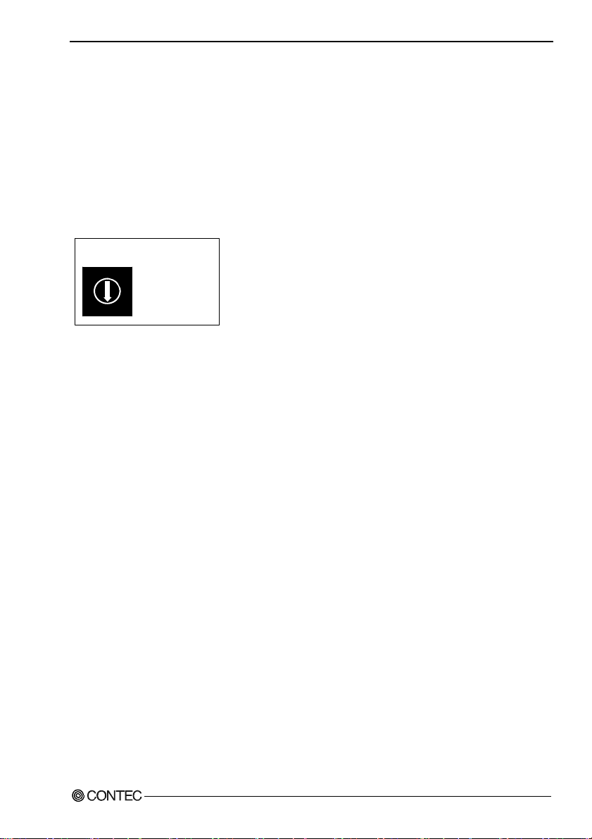
DANGER
WAR NI NG
CAUTION
DANGER indicates an imminently hazardous situation which, if not avoided, will
result in death or serious injury.
WARNING indicates a potentially hazardous situation which, if not avoided, could
result in death or serious injury.
CAUTION indicates a potentially hazardous situation which, if not avoided, may
result in minor or moderate injury or in property damage.
DIO-6464L-PE, DI-128L-PE, DO-128L-PE
6
Page 14

1. Before Using the Product
Handling Precautions
DANGER
Do not use the product where it is exposed to flamm able or corr osive ga s. Doi ng so m ay result in an
explosion, fire, electric shock, or failure.
CAUTION
- There are switches and jumpers on the product that need to be set in advance.
Be sure to check these before installing the product.
- Only set the switches and jumpers on the product to the specified settings.
Otherwise, the product may malfunction, overheat, or cause a failure.
- Do not strike or bend the product.
Otherwise, the product may malfunction, overheat, cause a failure or breakage.
- Do not touch the product's metal plated terminals (edge connector) with your hands.
Otherwise, the product may malfunction, overheat, or cause a failure.
If the terminals are touched by someone's hands, clean the terminals with industrial alcohol.
- Do not install or remove the product to or from the extension slot while the computer's power is turned
on. And also do not connect the product and external device while the power is turned on.
Otherwise, the product may malfunction, overheat, or cause a failure.
Be sure that the personal computer or the I/O extension unit power is turned off.
- When you use this product in a noisy environment or are nervous about noise, attach ferrite cores to the
connection cable.
- Make sure that your PC or extension unit can supply ample power to all the products installed.
Insufficiently energized products could malfunction, overheat, or cause a failure.
- The specifications of this pr oduct are subject t o cha nge wit hout notic e for en hancement and qua lity
improvement.
Even when using the product continuously, be sure to read the manual and understand the contents.
- Do not modify the product. CONTEC will b ear no responsibility for any problems, etc., resulting
from modifying this product.
- Regardless of the foregoing statements, CONTEC is not liable for any damages whatsoever
(including damages for loss of business profits) arising out of the use or inability to use this
CONTEC product or the information contained herein.
DIO-6464L-PE, DI-128L-PE, DO-128L-PE
7
Page 15
1. Before Using the Product
Environment
Use this product in the following environment. If used in an unauthorized environment, the board may
overheat, malfunction, or cause a failure.
Operating temperature
0 - 50°C
Humidity
10 - 90%RH (No condensation)
Corrosive gases
None
Floating dust particles
Not to be excessive
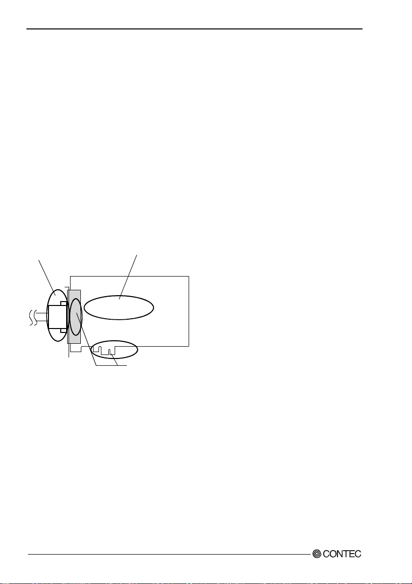
Inspection
Inspect the product periodically as follows to use it safely.
- Check that the bus connector
of the board and its cable have
been plugged correctly.
- Check that the board has
no dust or foreign matter adhering.
- The gold-plated leads of the bus connector
have no stain or corrosion.
Storage
When storing this product, keep it in its original packing fo rm.
(1) Put the product in the storage bag.
(2) Wrap it in the packing material, and then put it in the box.
(3) Store the package at room temperature at a place free from direct sunlight, moisture, shock,
vibration, magnetism, and static electricity.
Disposal
When disposing of the product, follow the disposal procedures stipulated under the relevant laws and
municipal ordinances.
DIO-6464L-PE, DI-128L-PE, DO-128L-PE
8
Page 16

2. Setup
2. Setup
This chapter explains how to set up the board.
What is Setup?
Setup means a series of steps to take before the product can be used.
Different steps are required for software and hardware.
The setup procedure varies with the OS and applications used.
Using the Board under Windows
Using the Driver Library API-PAC(W32)
This section describes the setup procedure to be performed before you can start developing application
programs for the board using the bundled CD-ROM “Driver Library API-PAC(W32)”.
Taking the following steps sets up the software and hardware. You can use the diagnosis program later
to check whether the software and hardware function normally.
Step 1 Installing the Software
Step 2 Setting the Hardware
Step 3 Installing the Hardware
Step 4 Initializing the Software
Step 5 Checking Operations with the Diagnosis Program
If Setup fails to be performed normally, see the “Setup Troubleshooting” section at the end of this
chapter.
Using the Board under Windows
Using Software Other than the Driver Library API-PAC(W32)
For setting up software other than API-PAC(W32), refer to the manual for that software. See also the
following parts of this manual as required.
This chapter Step 2 Setting the Hardware
This chapter Step 3 Installing the Hardware
Chapter 3 External Connection
Chapter 6 About Hardware
DIO-6464L-PE, DI-128L-PE, DO-128L-PE
9
Page 17

2. Setup
Using the Board under an OS Other than Windows
For using the board under Linux, see the following parts of this manual.
This chapter Step 2 Setting the Hardware
Chapter 3 External Connection
Chapter 5 About Software
Chapter 6 About Hardware
For using the board under an OS other than Windows and Linux, see the following parts of this manual.
This chapter Step 2 Setting the Hardware
Chapter 3 External Connection
Chapter 6 About Hardware
DIO-6464L-PE, DI-128L-PE, DO-128L-PE
10
Page 18
2. Setup
Step 1 Installing the Software
This section describes how to install the Driver libraries.
Before installing the hardware on your PC, install the Driver libraries from the bundled API-PAC(W32)
CD-ROM.
The following description assumes the operating system as Windows XP. Although some user
interfaces are different depending on the OS used, the basic procedure is the same.
About the driver to be used
Two digital I/O drivers are available : API-DIO(WDM) and API-DIO(98/PC).
API-DIO(WDM) is a new driver to perform digital I/O under Windows.
API-DIO(WDM) was developed to improve the conventional product version of API-DIO(98 /PC) in the
ease of use and functionality.
It is advisable to use API-DIO(WDM) for you to use an digital I/O device. API-DIO(WDM) will
support new OS and devices in the future but will not support Windows NT 4.0, Windows 95, ISA bus.
Use API-DIO(98/PC) if your operating environment contains such an unsupported piece of software or
hardware.
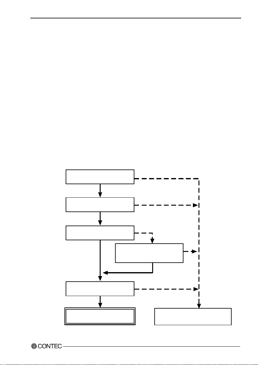
Check the following sele ct ion gu ide to eas il y se le ct th e driv e r to be us ed.
OS to be used
Windows Vista
Windows XP/Windows 2000
Device type
PCI bus, PC Card
Use the digital board for
the fisrt time?
Ye s
Language to be used
VC.Net, VB.Net, VC#.Net
VC6, VB6
API-DIO(WDM)
DIO-6464L-PE, DI-128L-PE, DO-128L-PE
Windows Me/98/95
Windows NT 4.0
ISA Bus
Already used.
The existing system
upgrade using
API-DIO(98/PC)?
No
VC2, 4, 5, VB4, 5,
Delphi, C++Builder
Ye s
API-DIO(98/PC)
11
Page 19
2. Setup
Starting the Install Program
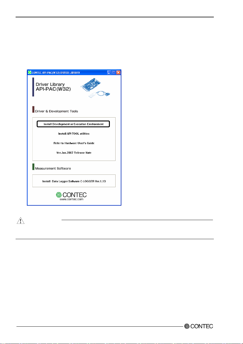
(1)
Load the CD-ROM [API-PAC(W32)] on your PC.
(2)
The API-PAC(W32) Installer window appears automatically.
If the panel does not appear, run (CD-ROM drive letter):\AUTORUN.exe.
(3)
Click on the [Install Development or Execution Environment] button.
* When using the Windows Vista, driver is automatically installed.
CAUTION
Before installing the software in Windows Vista, XP, Server 2003 and 2000, log in as a user with
administrator privileges.
DIO-6464L-PE, DI-128L-PE, DO-128L-PE
12
Page 20
2. Setup
Select API-DIO(WDM)
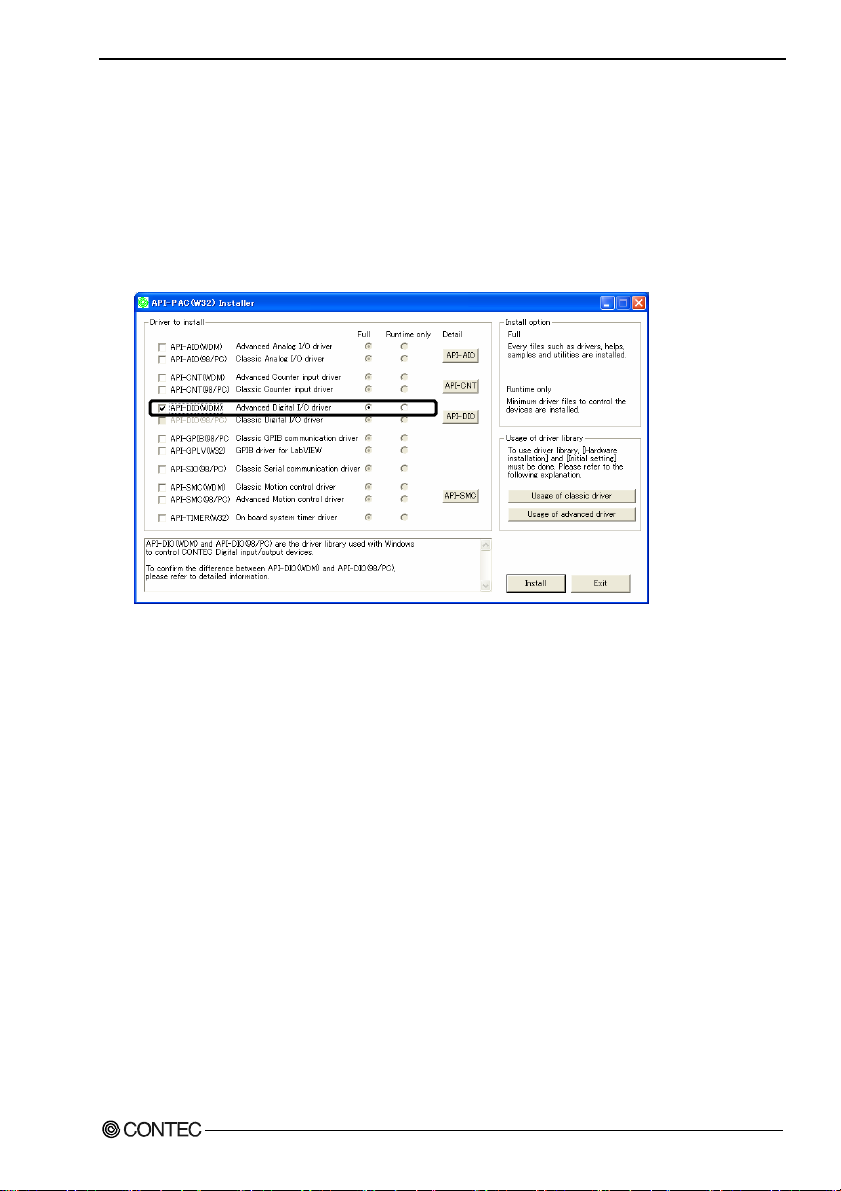
Selecting API-DIO(WDM)
(1)
The following dialog box appears to select “Driver to install” and “Install option”, “Usage of
driver library”.
(2)
Select the "Advanced Digital I/O driver".
(3)
Click on the [Install] button.
* Clicking the [API-DIO] button displays d etailed information about API-DIO(WDM) and
API-DIO(98/PC).
Run the installation
(1)
Complete the installation by following the instructions on the screen.
(2)
The Readme file appears when the installation is complete.
DIO-6464L-PE, DI-128L-PE, DO-128L-PE
13
Page 21
2. Setup
Select API-DIO(98/PC)
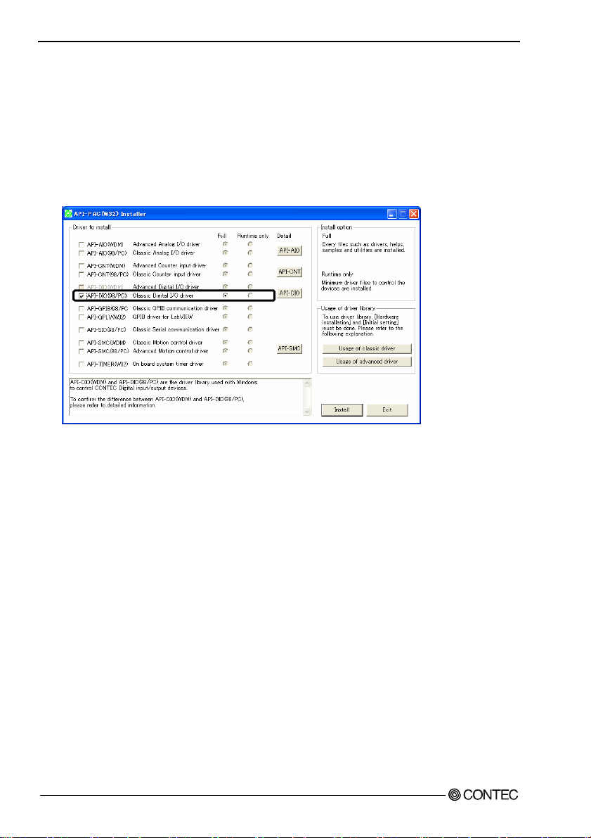
Selecting API-DIO(98/PC)
(1)
The following dialog box appears to select “Driver to install” and “Install option”, “Usage of
driver library”.
(2)
Select “Classic Digital I/O driver”.
(3)
Click on the [Install] button.
* Clicking on the [API-DIO] button displays detailed information on API-DIO(WDM),
API-DIO(98/PC).
DIO-6464L-PE, DI-128L-PE, DO-128L-PE
14
Page 22
2. Setup
Executing the Installation
(1)
Follow the on-screen instructions to proceed to install.
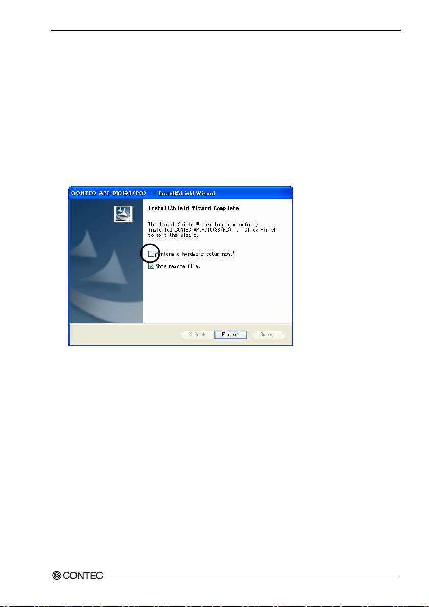
(2) When the required files have been copied, the “Perform a hardware setup now(API-TOOL
Configuration)” and “Show readme file” check boxes are displayed.
When you are installing the software or hardware for the first time:
1) Uncheck “Perform a hardware setup now”.
2) Click on the [Finish] button.
Go to Step 2 to set and plug the hardware.
* When the hardware has already been installed:
Check “Perform a hardware setup now(API-TOOL Configuration)”, then go to Step 4
“Initializing the Software”.
You have now finished installing the software.
DIO-6464L-PE, DI-128L-PE, DO-128L-PE
15
Page 23
2. Setup
Step 2 Setting the Hardware
This section describes how to set the board and plug it on your PC.
The board has some switches to be preset.
Check the on-board switches before plugging the board into an extension slot.
The board can be set up even with the factory defaults untouched. You can change board settings later.
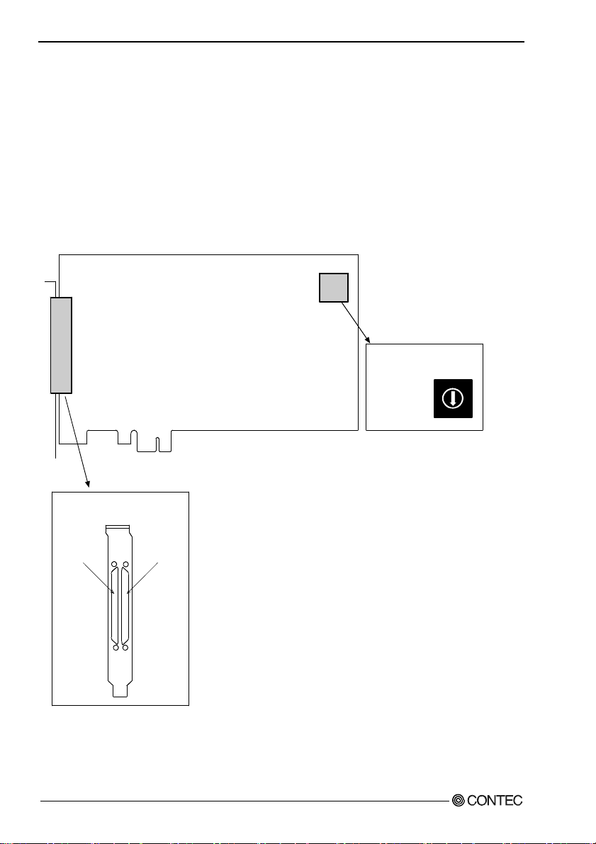
Parts of the Board and Factory Defaults
Figure 2.1. shows the names of major parts on the board.
Note that the switch setting shown below is the factory default.
DIO/DI/DO-xx-PE
SW1
BOARD ID
- Board ID setting switch
(SW1)
SW1
BOARD ID
9
8
7
6
5
4
3
2
0
1
A
B
C
D
E
F
- Interface connector
(CNA, CNB)
CNACNB
Figure 2.1. Component Locations
DIO-6464L-PE, DI-128L-PE, DO-128L-PE
16
Page 24
2. Setup
Setting the Board ID
If you install two or more boards on one personal computer, assign a different ID value to each of the
boards to distinguish them.
The board IDs can be set from 0 to Fh to identify up to sixteen boards.
If only one board is used, the original factory setting (Board ID = 0) should be used.
Setting Procedure
To set the board ID, use the rotary switch on the boar d. Tur n the SW 1 knob to set the board ID a s show n
below.
SW1
BOARD ID
8
9
A
7
6
B
5
C
4
D
0
1
E
F
Factory setting:
(Board ID = 0)
3
2
Figure 2.2. Board ID Settings (SW1)
DIO-6464L-PE, DI-128L-PE, DO-128L-PE
17
Page 25

2. Setup
Plugging the Board
(1) Before plugging the board, shut down the system, unplug the power code of you r PC.
(2) Remove the cover from the PC so that the board can be mounted.
(3) Plug the board into an extension slot.
(4) Attach the board bracket to the PC.
(5) Put the cover back into place.
CAUTION
- Do not touch the board's metal plated terminals (edge connector) with your hands.
Otherwise, the board may malfunction, overheat, or cause a failure.
If the terminals are touched by someone's hands, clean the terminals with industrial alcohol.
- Do not install or remove the board to or from the slot while the computer's or extension unit’s power is
turned on.
Otherwise, the board may malfunction, overheat, or cause a failure.
Be sure that the personal computer or the I/O extension unit power is turned off.
- Make sure that your PC or extension unit can supply ample power to all the boards installed.
Insufficiently energized boards could malfunction, overheat, or cause a failure.
DIO-6464L-PE, DI-128L-PE, DO-128L-PE
18
Page 26

2. Setup
Step 3 Installing the Hardware
For using an extension board under Windows, y ou have t o let the OS detect the I/O addresses and IRQ to
be used by the board. The process is referred to as installing the hardware.
In the case of using two or more boar ds, make sur e you install one by one with the F ound New Hardware
Wizard.
Turning on the PC
Turn on the power to your PC.
CAUTION
- The board cannot be properly installed unless the resources (I/O addresses and interrupt level) for
the board can be allocated. Before attempting to install the board, first determ ine what PC resource s
are free to use.
- The resources used by each board do not depend on the location of the PCI Express bus slot or the
board itself. If you remove two or more boards that have already been installed and then remount
one of them on the computer, it is unknown that which one of the sets of res ources previous ly
assigned to the two bo ards is assi gned to th e re moun ted bo ard . In th is c ase , you mus t ch e ck th e
resource settings.
When Using API-DIO(WDM)
(1) The “Found New Hardware Wizard” will be started.
Select “No, not this time” and then click the “Next” button.
DIO-6464L-PE, DI-128L-PE, DO-128L-PE
19
Page 27

2. Setup
(2) When “Multimedia Controller” is displayed, select “Install from a list or s
pecific
location[Advanced]” and then specify that folder on the CD-ROM which contains the setup
information (INF) file to register the board.
When the model name of hardware is displayed, select “Install the software automatically
[Recommended]” and then click on the “Next” button.
Source folder
The setup information (INF) file is contained in the following folder on the bundled CD-ROM.
Windows Vista, XP, Server 2003, 2000 \INF\Wdm\Dio
\INF\Wdm\Dio
DIO-6464L-PE, DI-128L-PE, DO-128L-PE
20
Page 28

2. Setup
* The name of the board
you have just added is
displayed.
- DIO-6464L-PE,
- DI-128L-PE,
- DO-128L-PE
You have now finished installing the hardware.
DIO-6464L-PE, DI-128L-PE, DO-128L-PE
21
Page 29

2. Setup
When Using API-DIO(98/PC)
(1) The “Found New Hardware Wizard” will be started.
Select “No, not this time” and then click the “Next” button.
(2) Select “Install from a list or s
pecific location[Advanced]” and then click the “Next” button.
DIO-6464L-PE, DI-128L-PE, DO-128L-PE
22
Page 30
2. Setup
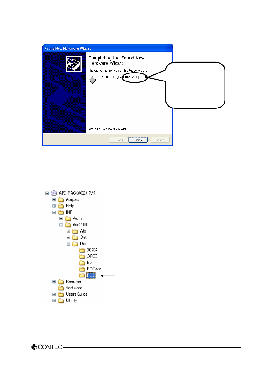
(3) Specify that folder on the CD-ROM which contains the setup information (INF) f ile to reg ist er th e
board.
* The name of the board
you have just added is
displayed.
- DIO-6464L-PE,
- DI-128L-PE,
- DO-128L-PE
Source folder
The setup information (INF) file is contained in the following folder on the bundled CD-ROM.
Windows Vista, XP, Server 2003, 2000 \INF\Win2000\Dio\PCI
Example of specifying the folder for use under Windows XP
\INF\Win2000\Dio\PCI
DIO-6464L-PE, DI-128L-PE, DO-128L-PE
23
Page 31

2. Setup
CAUTION
In Windows XP, the Hardware Wizard displays the following alert dialog box when you have
located the INF file. This dialog box appears, only indicating that the releva nt dr iver has not passe d
Windows Logo testing, an d it ca n be i gnored without developing any pro bl em wit h t he opera t i on o f
the board.
In this case, click on the [Continue Anyway] button.
You have now finished installing the hardware.
* The name of the board
you have just added is
displayed.
- DIO-6464L-PE,
- DI-128L-PE,
- DO-128L-PE
DIO-6464L-PE, DI-128L-PE, DO-128L-PE
24
Page 32

2. Setup
Step 4 Initializing the Software
The driver function library requires the initial setting to recognize the execution environment. It is
called the initializ ati on of th e D riv er li b rar y.
When U sin g API-DIO(WDM)
API-DIO(WDM) is initialized automatically during hardware installation. Therefore, if you want to use
it with its initial settings, you can skip the setting procedure described in Step 4. To change the device
name, follow the setting procedure shown below.
Setting the device name
(1) Run Device Manager. From [My Computer] - [Control Panel], select [System] and then select the
[Device Manager] tab.
(You can also open Device Manager by right clicking on My Computer and selecting Properties.)
* The name of the board
you have just added is
displayed.
- DIO-6464L-PE,
- DI-128L-PE,
- DO-128L-PE
(2) The installed hardware appears under the CONTEC Devices node. Open the CONTEC Devices
node and select the device you want to setup (the device name should appear highlighted). Click
[Properties].
DIO-6464L-PE, DI-128L-PE, DO-128L-PE
25
Page 33

2. Setup
(3) The property page for the device opens.
Enter the device name in the common settings tab page and then click [OK].
The device name you set here is used later when programming.
* The initial device name that appears is a default value. You can use this default name if you wish.
* Make sure that you do not use the same name for more than one device.
You have now finished installing the initial setting of Software.
DIO-6464L-PE, DI-128L-PE, DO-128L-PE
26
Page 34

2. Setup
When Usi ng API-DIO(98/PC)
(1) Open the Start Menu, then select “Programs” – “CONTEC API-PAC(W32)” – “API-TOOL
Configuration”.
(2) API-TOOL Configuration detects boards automatically.
The detected boards are listed.
Updating the Settings
(1) Select “Save setting to registry…” from the “File” menu.
You have now finished installing the initial setting of Software.
DIO-6464L-PE, DI-128L-PE, DO-128L-PE
27
Page 35

2. Setup
Step 5 Checking Operations with the Diagnosis Program
Use the diagnosis program to check that the board and driver software work normally, thereby you can
confirm that they have been set up correctly.
What is the Diagnosis Program?
The diagnosis program diagnoses the states of the board and driver software.
It can also be used as a si mple ch ec k er when an ex t ern al dev i ce i s actu all y co nn ect ed .
Using the “Diagnosis Report” feature reports the driver settings, the presence or absence of the board,
I/O status, and interrupt status.
Check Method
Connect the board to a remote device to test the input/output and check the execution environment.
For this board, prepare an external power supply (12 - 24VDC).
The Check Mate (CM-64(PC)E) comes in handy when you check digital I/O boards.
Check the board with the factor defaults untouched.
Connection diagram
Connector
Optional cable
PCB100/96PS-xx
To connect a device other than the Check Mate, see Chapter 3 “External Connection”.
CM-64(PC)E
GROUP 1
7 6 5 4 3 2 1 0
GROUP 3
7 6 5 4 3 2 1 0
GROUP 5
7 6 5 4 3 2 1 0
GROUP 7
7 6 5 4 3 2 1 0
ACK
External power
supply
12 - 24VDC
GROUP 0
7 6 5 4 3 2 1 0
GROUP 2
7 6 5 4 3 2 1 0
GROUP 4
7 6 5 4 3 2 1 0
GROUP 6
7 6 5 4 3 2 1 0
STB
POWER
CN3
DIO-6464L-PE, DI-128L-PE, DO-128L-PE
28
Page 36

2. Setup
Using the Diagnosis Program
Starting the Diagnosis Program for Use of API-DIO(WDM)
Click the [Diagnosis] button on the device property page to start the di agnosis progra m.
DIO-6464L-PE, DI-128L-PE, DO-128L-PE
29
Page 37

2. Setup
Startin g the Dia gnosis Pro gram for Use of API-DIO(98/PC)
Select the board in the API-TOOL Configuration windows, then run the Diagnosis Program. Follow the
instructions on screen.
* The name of the board you have just added is displayed.
* The name of the board
you have just added is
displayed.
- DIO-6464L-PE,
- DI-128L-PE,
- DO-128L-PE
DIO-6464L-PE, DI-128L-PE, DO-128L-PE
30
Page 38

2. Setup
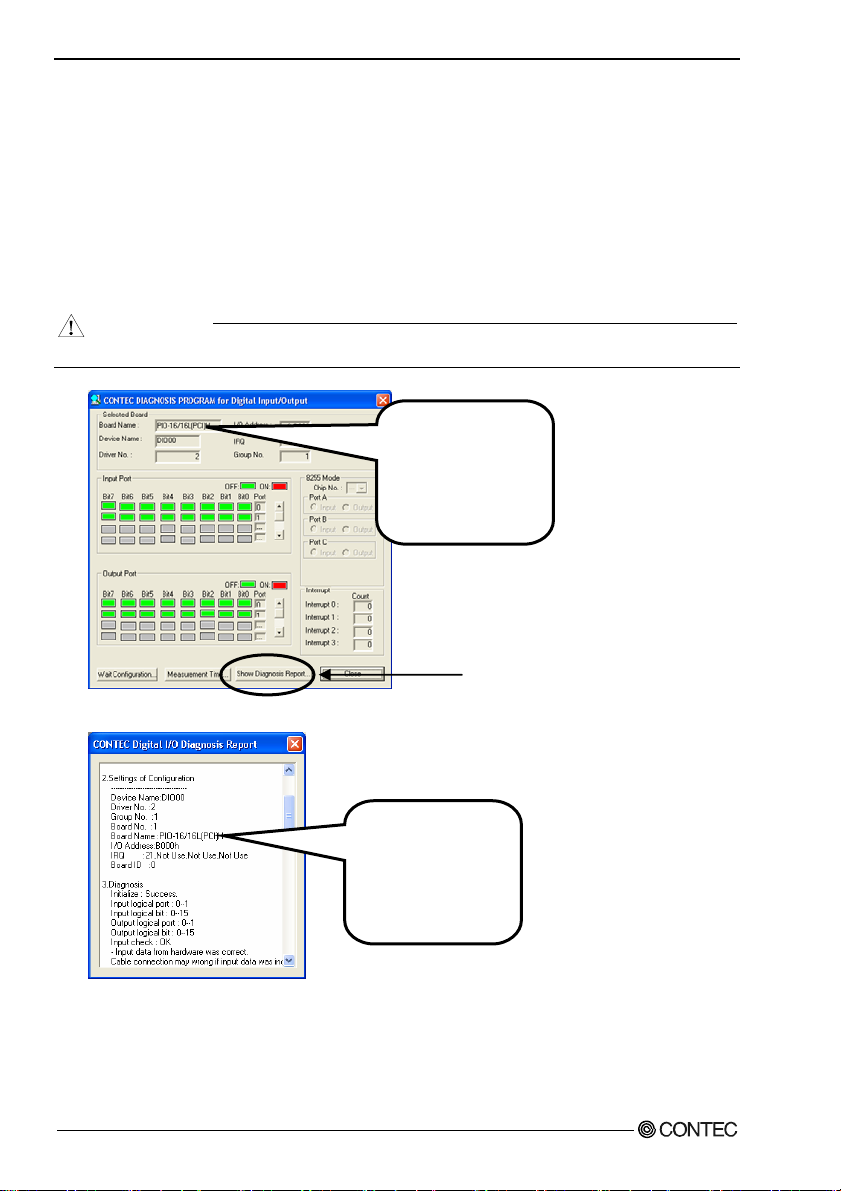
Checking Digital Inputs and Outputs
The main panel of the Diagnosis Program appears.
You can check the current operation states of the board in the following boxes:
“Input Port” :
“Output Port” :
“Interrupt” :
Displays input values bit by bit at fixed time i ntervals .
Mouse operation allows the data to output or display.
Displays the number of interrupts detected bit by bit.
* The name of the board
you have just added is
displayed.
- DIO-6464L-PE,
- DI-128L-PE,
- DO-128L-PE
To use the wait time control feature, click on t he [W ait C onfiguration] button. U se t he feat ure w hen t he
wait time based on the DioWait or DioWaitEx function is not normal.
To use the function executi on time measurem ent feature, click on t he [Measurem ent Time] button. Enter
the I/O start port and the number of ports, then press the measurement button. The time for each
execution of a function will be measured.
DIO-6464L-PE, DI-128L-PE, DO-128L-PE
31
Page 39
2. Setup
Diagnosis Report
(1) Clicking on the [Show Diagnosis Report] button displays detailed da ta such as bo ard settin gs and
the diagnosis results while saving them in text format.
When it is API-DIO(WDM), file name to save the result is displayed.
When it is API-DIO(98/PC), the result is saved to the folder in wh i ch to in sta ll (Prog ra m
Files\CONTEC\API-PAC(W32)) by the text file (DioRep.txt) an d t h en displaye d .
The Diagnosis Program performs “board presence/absence check”, “driver file test”, “board setting
test”, and so on.
CAUTION
Before executing diagnosis report output, unplug the cable from the board.
* The name of the board
you have just added is
displayed.
- DIO-6464L-PE,
- DI-128L-PE,
- DO-128L-PE
(2) A diagnosis report is displayed as shown below.
* The name of the board
you have just added is
displayed.
- DIO-6464L-PE,
- DI-128L-PE,
- DO-128L-PE
DIO-6464L-PE, DI-128L-PE, DO-128L-PE
32
Click on [Show
Diagnosis Report].
Page 40

2. Setup
Setup Troubleshooting
Symptoms and Actions
No output can be obtained.
Use API-TOOL Configuration to check whether the board name setting is wrong.
The board works with the Diagnosis Program but not with an application.
The Diagnosis Program is coded with API-TOOL functions. As long as the board operates with the
Diagnosis Program, it is to operate with other applications as well. In such cases, review your program
while paying attention to the following points:
- Check the arguments to functions and their return values.
- When the board is an isolated type, it has a time lag for its response between the output by a function
and the actual output. Consider the execution intervals between functions.
The OS won’t normally get started or detect the board.
[Windows Vista, XP, Server 2003, 2000]
Turn off the power to your PC, then unplug the board. Restart th e OS and delete the board setting s of
API-TOOL Configuration. Turn off the PC ag ai n, pl ug the board, a nd res tart the OS. Let the OS detect
the board and use API-TOOL Configuration to register board settings.
If your problem cannot be resolved
Contact your retailer.
DIO-6464L-PE, DI-128L-PE, DO-128L-PE
33
Page 41

2. Setup
DIO-6464L-PE, DI-128L-PE, DO-128L-PE
34
Page 42

3. External Connection
3. External Connection
This chapter describes the interface connectors on the board and the external I/O circuits.
Check the information available here when connecting an external device.
How to connect the connectors
Connector shape
The on-board interface connector (CNA, CNB) is used when connecting this product and the external
devices.
Interface connector
CNACNB
- Connector used
HDRA-E100W1LFDT1EC-SL+
[mfd by HONDA
TSUSHIN KOGYO CO., LTD.]
or equivalent to it
- Applicable connector
HDRA-E100MA1 [mfd by HONDA
TSUSHIN KOGYO CO., LTD.]
* Please refer to chapter 1 for more information on the supported cable and accessories.
Figure 3.1. Inte r face C onn ector (CNA, CNB) Shape
DIO-6464L-PE, DI-128L-PE, DO-128L-PE
35
Page 43

3. External Connection
Connector Pin Assignment
Pin Assignments of DIO-6464L-PE Interface Connector (CNA, CNB)
Common
P-E/F 100 50 P-A/B
plus pin for
+E/+F
output
P-E/F 99 49 P-A/B
ports
O-F7 98 48 O-B7 N.C. 3 53 N.C.
O-F6 97 47 O-B6 N.C. 4 54 N.C.
O-F5 96 46 O-B5 N.C. 5 55 N.C.
O-F4 95 45 O-B4 N.C. 6 56 N.C.
+F port
(Output)
O-F3 94 44 O-B3 * I-00 7 57 I-40
O-F2 93 43 O-B2 * I-01 8 58 I-41
O-F1 92 42 O-B1 * I-02 9 59 I-42
O-F0 91 41 O-B0
O-E7 90 40 O-A7 * I-04 11 61 I-44
O-E6 89 39 O-A6 * I-05 12 62 I-45
O-E5 88 38 O-A5 * I-06 13 63 I-46
O-E4 87 37 O-A4
+E port
(Output)
O-E3 86 36 O-A3 * I-10 15 65 I-50
O-E2 85 35 O-A2 * I-11 16 66 I-51
O-E1 84 34 O-A1 * I-12 17 67 I-52
O-E0 83 33 O-A0
N-E/F 82 32 N-A/B * I-14 19 69 I-54
N-E/F 81 31 N-A/B * I-15 20 70 I-55
Common
N-E/F 80 30 N-A/B * I-16 21 71 I-56
minus pin
for
N-E/F 79 29 N-A/B
+E/+F
output
N-E/F 78 28 N-A/B P-0/ 1 23 73 P -4/5
ports
N-E/F 77 27 N-A/B
N.C. 76 26 N.C. N.C. 25 75 N.C.
N.C. 75 25 N.C. N.C. 26 76 N.C.
Common
P-C/D 74 24 P-8/ 9 N.C. 27 77 N.C.
plus pin for
+C/+D
output
P-C/D 73 23 P-8/ 9
ports
O-D7 72 22 O-97 N.C. 29 79 N.C.
O-D6 71 21 O-96 N.C. 30 80 N.C.
O-D5 70 20 O-95 N.C. 31 81 N.C.
O-D4 69 19 O-94 N.C. 32 82 N.C.
+D port
(Output)
O-D3 68 18 O-93 I-20 33 83 I-60
O-D2 67 17 O-92 I-21 34 84 I-61
O-D1 66 16 O-91 I-22 35 85 I-62
O-D0 65 15 O-90
O-C7 64 14 O-87 I-24 37 87 I-64
O-C6 63 13 O-86 I-25 38 88 I-65
O-C5 62 12 O-85 I-26 39 89 I-66
O-C4 61 11 O-84
+C port
(Output)
O-C3 60 10 O-83 I-30 41 91 I-70
O-C2 59 9 O-82 I-31 42 92 I-71
O-C1 58 8 O-81 I-32 43 93 I-72
O-C0 57 7 O-80
N-C/D 56 6 N-8/9 I-34 45 95 I-74
N-C/D 55 5 N-8/9 I-35 46 96 I-75
Common
N-C/D 54 4 N-8/9 I-36 47 97 I-76
minus pin
for
N-C/D 53 3 N-8/9
+C/+D
output
N-C/D 52 2 N-8/9 P-2/ 3 49 99 P-6/7
ports
N-C/D 51
CNB
100 50
51 1
1 N-8/9
* I-00 - I-17 can be used as interrupt signal.
Common
plus pin for
+A/+B
output
ports
+B port
(Output)
+A port
(Output)
Common
minus pin
for
+A/+B
output
ports
Common
plus pin for
+8/+9
output
ports
+9 port
(Output)
+8 port
(Output)
Common
minus pin
for
+8/+9
output
ports
1 51
N.C.
N.C. 2 52 N.C.
* I-03 10 60 I-43
+0 port
(Input)
CNA
* I-07 14 64 I-47
* I-13 18 68 I-53
+1 port
(Input)
* I-17 22 72 I-57
Common
plus pin for
+0/+1 input
P-0/1 24 74 P-4/5
ports
N.C. 28 78 N.C.
I-23 36 86 I-63
+2 Port
(Input)
I-27 40 90 I-67
I-33 44 94 I-73
+3 Port
(Input)
I-37 48 98 I-77
Common
plus pin
for +2/+3
P-2/3 50
input ports
151
50 100
N.C.
100 P-6/7
+4 port
(Input)
+5 port
(Input)
Common
plus pin for
+4/+5 input
ports
+6 port
(Input)
+7 Port
(Input)
Common
plus pin
for +6/+7
input ports
DIO-6464L-PE, DI-128L-PE, DO-128L-PE
36
Page 44

3. External Connection
I-00 - I-77 64 channels input signal. Connect o utput signals from the external device to these pins.
O-80 - O-F7 64 channels output signal. Connect input signals from the external device to these pins.
P-0/1 - P-6/7 Connect the positive side of the external power supply. These pins are common to 16 channels input signal.
P-8/9 - P-E/F Connect the positive side of the external power supply. These pins are common to 16 channels output signal.
N-8/9 - N-E/F Connect the negative side of the external power supply. These pins are common to 16 channels output signal. One pin permissible current of the
connector is 0.3A. Please connect necess ary number of pins for the corresponding total current of the output 16 channels. When 16 channels are used by
the output full ratings (100m A per 1 channel), it is necessary to connect six all.
N.C. This pin is left unconnected.
Figure 3.2. Pin Assignments of Interface Connector (CNA, CNB) < DIO-6464L-PE >
DIO-6464L-PE, DI-128L-PE, DO-128L-PE
37
Page 45

3. External Connection
Pin Assignments of DI-128L-PE Interface Connector (CNA, CNB)
Common
P-E/F 100 50 P-A/B
plus pin for
+E/+F
input ports
P-E/F 99 49 P-A/B
I-F7 98 48 I-B7 N. C. 3 53 N.C.
I-F6 97 47 I-B6 N. C. 4 54 N.C.
I-F5 96 46 I-B5 N. C. 5 55 N.C.
I-F4 95 45 I-B4 N. C. 6 56 N.C.
+F port
(Input)
I-F3 94 44 I-B3 * I-00 7 57 I-40
I-F2 93 43 I-B2 * I-01 8 58 I-41
I-F1 92 42 I-B1 * I-02 9 59 I-42
I-F0 91 41 I-B0
I-E7 90 40 I-A7 * I-04 11 61 I-44
I-E6 89 39 I-A6 * I-05 12 62 I-45
I-E5 88 38 I-A5 * I-06 13 63 I-46
I-E4 87 37 I-A4
+E port
(Input)
I-E3 86 36 I-A3 * I-10 15 65 I-50
I-E2 85 35 I-A2 * I-11 16 66 I-51
I-E1 84 34 I-A1 * I-12 17 67 I-52
I-E0 83 33 I-A0
N.C. 82 32 N.C. * I-14 19 69 I-54
N.C. 81 31 N.C. * I-15 20 70 I-55
N.C. 80 30 N.C. * I-16 21 71 I-56
N.C. 79 29 N.C.
N.C. 78 28 N.C. P-0/ 1 23 73 P-4/5
N.C. 77 27 N.C.
N.C. 76 26 N.C. N.C. 25 75 N.C.
N.C. 75 25 N.C. N.C. 26 76 N.C.
Common
P-C/D 74 24 P-8/ 9 N.C. 27 77 N.C.
plus pin for
+C/+D
input ports
P-C/D 73 23 P-8/ 9
I-D7 72 22 I-97 N.C. 29 79 N.C.
I-D6 71 21 I-96 N.C. 30 80 N.C.
I-D5 70 20 I-95 N.C. 31 81 N.C.
I-D4 69 19 I-94 N.C. 32 82 N.C.
+D port
(Input)
I-D3 68 18 I-93 I-2 0 33 83 I-60
I-D2 67 17 I-92 I-2 1 34 84 I-61
I-D1 66 16 I-91 I-2 2 35 85 I-62
I-D0 65 15 I-90
I-C7 64 14 I-8 7 I-24 37 87 I-6 4
I-C6 63 13 I-8 6 I-25 38 88 I-6 5
I-C5 62 12 I-8 5 I-26 39 89 I-6 6
I-C4 61 11 I-8 4
+C port
(Input)
I-C3 60 10 I-8 3 I-30 41 91 I-7 0
I-C2 59 9 I-82 I-31 42 92 I-71
I-C1 58 8 I-81 I-32 43 93 I-72
I-C0 57 7 I-80
N.C. 56 6 N. C. I-34 45 95 I-74
N.C. 55 5 N. C. I-35 46 96 I-75
N.C. 54 4 N. C. I-36 47 97 I-76
N.C. 53 3 N. C.
N.C. 52 2 N. C. P-2/3 49 99 P-6/7
N.C. 51
CNB
100 50
51 1
1 N.C.
* I-00 - I-17 can be used as interrupt signal.
I-00 - I-F7 128 channels input signal. Connect out put signals from the external device to these pins.
P-0/1 - P-E/F Connect the positive side of the external power supply. These pins are common to 16 channels input signal.
N.C. This pin is left unconnec ted.
Common
plus pin for
+A/+B
input ports
+B port
(Input)
+A port
(Input)
Common
plus pin for
+8/+9 input
ports
+9 port
(Input)
+8 port
(Input)
1 51
N.C.
N.C. 2 52 N.C.
* I-03 10 60 I-43
+0 port
(Input)
* I-07 14 64 I-47
* I-13 18 68 I-53
+1 port
(Input)
* I-17 22 72 I-57
Common
plus pin for
+0/+1 input
ports
P-0/1 24 74 P-4/5
N.C. 28 78 N.C.
I-23 36 86 I-63
+2 Port
(Input)
I-27 40 90 I-67
I-33 44 94 I-73
+3 Port
(Input)
I-37 48 98 I-77
Common
plus pin
for +2/+3
input ports
P-2/3 50
CNA
151
50 100
N.C.
100 P-6/7
Figure 3.3. Pin Assignments of Interface Connector (CNA, CNB) < DI-128L-PE >
+4 port
(Input)
+5 port
(Input)
Common
plus pin for
+4/+5 input
ports
+6 port
(Input)
+7 Port
(Input)
Common
plus pin
for +6/+7
input ports
DIO-6464L-PE, DI-128L-PE, DO-128L-PE
38
Page 46

3. External Connection
Pin Assignments of DO-128L-PE Interface Connector (CNA, CNB)
Common
P-E/F 100 50 P-A/B
plus pin for
+E/+F
output
P-E/F 99 49 P-A/B
ports
O-F7 98 48 O-B7
O-F6 97 47 O-B6
O-F5 96 46 O-B5
O-F4 95 45 O-B4
+F port
(Output)
O-F3 94 44 O-B3 O-00 7 57 O-40
O-F2 93 43 O-B2 O-01 8 58 O-41
O-F1 92 42 O-B1 O-02 9 59 O-42
O-F0 91 41 O-B0
O-E7 90 40 O-A7 O-04 11 61 O-44
O-E6 89 39 O-A6 O-05 12 62 O-45
O-E5 88 38 O-A5 O-06 13 63 O-46
O-E4 87 37 O-A4 O-07 14 64 O-47
+E port
(Output)
O-E3 86 36 O-A3
O-E2 85 35 O-A2 O-11 16 66 O-51
O-E1 84 34 O-A1 O-12 17 67 O-52
O-E0 83 33 O-A0
N-E/F 82 32 N-A/B O-14 19 69 O-54
N-E/F 81 31 N-A/B O-15 20 70 O-55
Common
N-E/F 80 30 N-A/B O-16 21 71 O-56
minus pin
N-E/F 79 29 N-A/B
for
+E/+F
output
N-E/F 78 28 N-A/B P-0/1 23 73 P-4/5
ports
N-E/F 77 27 N-A/B
N.C. 76 26 N.C. N.C. 25 75 N.C.
N.C. 75 25 N.C. N.C. 26 76 N.C.
Common
P-C/D 74 24 P- 8/9 N-2/ 3 27 77 N-6/7
plus pin for
+C/+D
output
P-C/D 73 23 P- 8/9
ports
O-D7 72 22 O-97 N-2/3 29 79 N-6/7
O-D6 71 21 O-96 N-2/3 30 80 N-6/7
O-D5 70 20 O-95 N-2/3 31 81 N-6/7
O-D4 69 19 O-94
+D port
(Output)
O-D3 68 18 O-93 O-20 33 83 O-60
O-D2 67 17 O-92 O-21 34 84 O-61
O-D1 66 16 O-91 O-22 35 85 O-62
O-D0 65 15 O-90
O-C7 64 14 O-87 O-24 37 87 O-64
O-C6 63 13 O-86 O-25 38 88 O-65
O-C5 62 12 O-85 O-26 39 89 O-66
O-C4 61 11 O-84
+C port
(Output)
O-C3 60 10 O-83 O-30 41 91 O-70
O-C2 59 9 O-82 O-31 42 92 O-71
O-C1 58 8 O-81 O-32 43 93 O-72
O-C0 57 7 O-80
N-C/D 56 6 N-8/9 O-34 45 95 O-74
N-C/D 55 5 N-8/9 O-35 46 96 O-75
Common
N-C/D 54 4 N-8/9 O-36 47 97 O-76
minus pin
N-C/D 53 3 N-8/9
for
+C/+D
output
N-C/D 52 2 N-8/9 P-2/ 3 49 99 P-6/7
ports
N-C/D 51
CNB
100 50
51 1
1 N-8/9
Common
plus pin for
+A/+B
output
ports
+B port
(Output)
+A port
(Output)
Common
minus pin
for
+A/+B
output
ports
Common
plus pin for
+8/+9
output
ports
+9 port
(Output)
+8 port
(Output)
Common
minus pin
for
+8/+9
output
ports
1 51
N-0/1
Common
minus pin
for +0/+1
output
ports
+0 port
(Output)
+1 port
(Output)
Common
plus pin for
+0/+1
output
ports
Common
minus pin
for +2/+3
output
ports
+2 port
(Output)
+3 Port
(Output)
Common
plus pin
for +2/+3
output
ports
2 52 N-4/5
N-0/1
3 53 N-4/5
N-0/1
4 54 N-4/5
N-0/1
5 55 N-4/5
N-0/1
6 56 N-4/5
N-0/1
O-03 10 60 O-43
O-10 15 65 O-50
O-13 18 68 O-53
O-17 22 72 O-57
P-0/1 24 74 P-4/5
N-2/3 28 78 N-6/7
N-2/3 32 82 N-6/7
O-23 36 86 O-63
O-27 40 90 O-67
O-33 44 94 O-73
O-37 48 98 O-77
P-2/3 50
151
50 100
CNA
N-4/5
100 P- 6/7
Common
minus pin
for +4/+5
output
ports
+4 port
(Output)
+5 port
(Output)
Common
plus pin for
+4/+5
output
ports
Common
minus pin
for +6/+7
output
ports
+6 port
(Output)
+7 Port
(Output)
Common
plus pin
for +6/+7
output
ports
O-00 - O-F7 128 channels output signal. Connect input signals from the external device to these pins.
P-0/1 - P-E/F Connect the positive side of the external power supply. These pins are common to 16 channels output signal.
N-0/1 - N-E/F Connect the negative side of the external power supply. These pins are common to 16 channels output signal. One pin permissible current of the
connector is 0.3A. Please co nnect necessary number of pins for the corresponding total cur rent of the output 16 channels. When 16 channels are used by
the output full ratings (100m A per 1 channel), it is necessary to connect six all.
N.C. This pin is left unconnec ted.
Figure 3.4. Pin Assignments of Interface Connector (CNA, CNB) < DO-128L-PE >
DIO-6464L-PE, DI-128L-PE, DO-128L-PE
39
Page 47

3. External Connection
Pin assignments for connecting to the PCB100/96PS or PCB 100WS
The figure below shows the correspondence between the option cable pins and signals.
< Pin assignments for connecting a PCB100/96PS or PCB100WS to the DIO-6464L-PE >
PCB100/96PS
Common
N-C/D B01 A01 N -8/9
minus pin
for +C/+D
output
N-C/D B02 A02 N -8/9
ports
O-C0 B03 A03 O-80 I-40 B03 A03 I-0 0
O-C1 B04 A04 O-81 I-41 B04 A04 I-0 1
O-C2 B05 A05 O-82 I-42 B05 A05 I-0 2
O-C3 B06 A06 O-83 I-43 B06 A06 I-0 3
+C port
(Output)
O-C4 B07 A07 O-84 I-44 B07 A07 I-0 4
O-C5 B08 A08 O-85 I-45 B08 A08 I-0 5
O-C6 B09 A09 O-86 I-46 B09 A09 I-0 6
O-C7 B10 A10 O-87
O-D0 B11 A11 O-90 I-50 B11 A11 I-10
O-D1 B12 A12 O-91 I-51 B12 A12 I-11
O-D2 B13 A13 O-92 I-52 B13 A13 I-12
O-D3 B14 A14 O-93 I-53 B14 A14 I-13
+D port
(Output)
O-D4 B15 A15 O-94 I-54 B15 A15 I-14
O-D5 B16 A16 O-95 I-55 B16 A16 I-15
O-D6 B17 A17 O-96 I-56 B17 A17 I-16
O-D7 B18 A18 O-97
Common
P-C/D B19 A19 P-8/9 P-4/5 B19 A19 P-0/1
plus pin
for +C/+D
output
P-C/D B20 A20 P-8/9
ports
N.C. B21 A21 N.C. N.C. B21 A21 N.C.
N.C. B22 A22 N.C. N.C. B22 A22 N.C.
N.C. B23 A23 N.C. N.C. B23 A23 N.C.
Unconnected
N.C. B24 A24 N.C. N.C. B24 A24 N.C.
N.C. B25 A25 N.C. N.C. B25 A25 N.C.
N.C. B26 A26 N.C. N.C. B26 A26 N.C.
N.C. B27 A27 N.C. N.C. B27 A27 N.C.
N.C. B28 A28 N.C.
Common
N-E/F B29 A29 N-A/B N.C. B29 A29 N.C.
minus pin
for +E/+F
output
N-E/F B30 A30 N-A/B
ports
O-E0 B31 A31 O-A0 I-60 B31 A31 I-2 0
O-E1 B32 A32 O-A1 I-61 B32 A32 I-2 1
O-E2 B33 A33 O-A2 I-62 B33 A33 I-2 2
O-E3 B34 A34 O-A3 I-63 B34 A34 I-2 3
+E port
(Output)
O-E4 B35 A35 O-A4 I-64 B35 A35 I-2 4
O-E5 B36 A36 O-A5 I-65 B36 A36 I-2 5
O-E6 B37 A37 O-A6 I-66 B37 A37 I-2 6
O-E7 B38 A38 O-A7
O-F0 B39 A3 9 O-B0 I-70 B39 A39 I-30
O-F1 B40 A4 0 O-B1 I-71 B40 A40 I-31
O-F2 B41 A4 1 O-B2 I-72 B41 A41 I-32
O-F3 B42 A4 2 O-B3 I-73 B42 A42 I-33
+F port
(Output)
O-F4 B43 A4 3 O-B4 I-74 B43 A43 I-34
O-F5 B44 A4 4 O-B5 I-75 B44 A44 I-35
O-F6 B45 A4 5 O-B6 I-76 B45 A45 I-36
O-F7 B46 A4 6 O-B7
Common
P-E/F B47 A4 7 P-A/B
plus pin
for +E/+F
output
P-E/F B48
ports
For connecting the boardCNB
[96]
[48]
B01
B48 A48
[49]
[1]
A01
A48 P -A/B
* [ ] shows pin numbers specified by HONDA TSUSHIN KOGYO CO., LTD.
Common
minus pin
for +8/+9
output
ports
+8 port
(Output)
+9 port
(Output)
Common
plus pin
for +8/+9
output
ports
Unconnected
Common
minus pin
for +A/+B
output
ports
+A port
(Output)
+B port
(Output)
Common
plus pin
for +A/+B
output
ports
B01 A01
Unconnected
Unconnected
N.C.
N.C. B02 A02 N.C.
+4 port
(Input)
I-47 B10 A10 I-07
+5 port
(Input)
I-57 B18 A18 I-17
Common
plus pin
for +4/+5
input ports
P-4/5 B20 A20 P-0/1
N.C. B28 A28 N.C.
N.C.
+6 port
(Input)
I-67 B38 A38 I-27
+7 port
(Input)
I-77 B46 A46 I-37
Common
P-6/7
plus pin
for +6/+7
input ports
P-6/7 B48
For connecting the boardCNA
B01
B30 A30 N. C.
B48 A48
B47 A47 P-2/3
N.C.
[96]
[48]
A01
[49]
[1]
A48 P-2/3
Figure 3.5. Pin Assignments of PCB100/96PS < DIO-6464L-PE >
DIO-6464L-PE, DI-128L-PE, DO-128L-PE
40
Unconnected
+0 port
(Input)
+1 port
(Input)
Common
plus pin
for +0/+1
input ports
Unconnected
+2 port
(Input)
+3 port
(Input)
Common
plus pin
for +2/+3
input ports
Page 48

3. External Connection
PCB100WS
CN A
CN BCN A
CN B
N.C. 19 N.C. 19
Common
plus pin
for +8/+9
P-8/9 18 37 P-A/B
output
ports
O-97 17 36 O-B7 I-17 17 36 I-37
O-96 16 35 O-B6 I-16 16 35 I-36
O-95 15 34 O-B5 I-15 15 34 I-35
O-94 14 33 O-B4 I-14 14 33 I-34
+9 port
(Output)
O-93 13 32 O-B3 I-13 13 32 I-33
O-92 12 31 O-B2 I-12 12 31 I-32
O-91 11 30 O-B1 I-11 11 30 I-31
O-90 10 29 O-B0
O-87 9 28 O-A7 I-07 9 28 I-27
O-86 8 27 O-A6 I-06 8 27 I-26
O-85 7 26 O-A5 I-05 7 26 I-25
O-84 6 25 O-A4 I-04 6 25 I-24
+8 port
(Output)
O-83 5 24 O-A3 I-03 5 24 I-23
O-82 4 23 O-A2 I-02 4 23 I-22
O-81 3 22 O-A1 I-01 3 22 I-21
O-80 2 21 O-A0
Common
minus pin
for +8/+9
N-8/9 1
output
ports
N.C. 19 N.C. 19
Common
plus pin
for +C/+D
P-C/D 18 37 P-E/F
output
ports
O-D7 17 36 O-F7 I-57 17 36 I-77
O-D6 16 35 O-F6 I-56 16 35 I-76
O-D5 15 34 O-F5 I-55 15 34 I-75
O-D4 14 33 O-F4 I-54 14 33 I-74
+D port
(Output)
O-D3 13 32 O-F3 I-53 13 32 I-73
O-D2 12 31 O-F2 I-52 12 31 I-72
O-D1 11 30 O-F1 I-51 11 30 I-71
O-D0 10 29 O-F0
O-C7 9 28 O-E7 I-47 9 28 I-67
O-C6 8 27 O-E6 I-46 8 27 I-66
O-C5 7 26 O-E5 I-45 7 26 I-65
O-C4 6 25 O-E4 I-44 6 25 I-64
+C port
(Output)
O-C3 5 24 O-E3 I-43 5 24 I-63
O-C2 4 23 O-E2 I-42 4 23 I-62
O-C1 3 22 O-E1 I-41 3 22 I-61
O-C0 2 21 O-E0
Common
minus pin
for +C/+D
N-C/D 1
output
ports
CNA of PCB100WS
connecting to the board CNB
19
1
CNB of PCB100WS
connecting to the board CNB
19
1
37
20
37
20
20 N-A/B
20 N-E/F
Common
plus pin
for +A/+B
output
ports
+B port
(Output)
+A port
(Output)
Common
minus pin
for +A/+B
output
ports
Common
plus pin
for +E/+F
output
ports
+F port
(Output)
+E port
(Output)
Common
minus pin
for +E/+F
output
ports
Common
plus pin
for
+0/+1
input
ports
+1 port
(Input)
+0 port
(Input)
N.C. 1
Common
plus pin
for
+4/+5
input
ports
+5 port
(Input)
+4 port
(Input)
N.C. 1
P-0/1 18 37 P-2/3
CNA of PCB100WS
connecting to the board CNA
19
I-10 10 29 I-30
I-00 2 21 I-20
P-4/5 18 37 P-6/7
connecting t o the board CNA
19
I-50 10 29 I-70
I-40 2 21 I-60
1
CNB of PCB100WS
1
37
20
20 N.C.
37
20
20 N.C.
Figure 3.6. Pin Assignments of PCB100WS < DIO-6464L-PE >
Common
plus pin
for
+2/+3
input
ports
+3 port
(Input)
+2 port
(Input)
Common
plus pin
for
+6/+7
input
ports
+7 port
(Input)
+6 port
(Input)
DIO-6464L-PE, DI-128L-PE, DO-128L-PE
41
Page 49

3. External Connection
< Pin assignments for connecting a PCB100/96PS or PCB100WS to the DI-128L-PE >
PCB100/96PS
Unconnected
Unconnected
* [ ] shows pin numbers specified by HONDA TSUSHIN KOGYO CO., LTD.
N.C. B01 A01 N.C. N.C. B0 1 A01 N.C.
N.C. B02 A02 N.C.
I-C0 B03 A03 I-80 I-40 B03 A03 I -00
I-C1 B04 A04 I-81 I-41 B04 A04 I -01
I-C2 B05 A05 I-82 I-42 B05 A05 I -02
I-C3 B06 A06 I-83 I-43 B06 A06 I -03
+C port
(Input)
I-C4 B07 A07 I-84 I-44 B07 A07 I -04
I-C5 B08 A08 I-85 I-45 B08 A08 I -05
I-C6 B09 A09 I-86 I-46 B09 A09 I -06
I-C7 B10 A10 I-87
I-D0 B11 A11 I-90 I -50 B11 A11 I-10
I-D1 B12 A12 I-91 I -51 B12 A12 I-11
I-D2 B13 A13 I-92 I -52 B13 A13 I-12
I-D3 B14 A14 I-93 I -53 B14 A14 I-13
+D port
(Input)
I-D4 B15 A15 I-94 I -54 B15 A15 I-14
For connecting the boardCNB
I-D5 B16 A16 I-95 I -55 B16 A16 I-15
I-D6 B17 A17 I-96 I -56 B17 A17 I-16
I-D7 B18 A18 I-97
Common
P-C/D B19 A19 P-8/9 P-4/5 B19 A19 P-0/1
plus pin
for +C/+D
output
P-C/D B20 A20 P-8/9
ports
N.C. B21 A21 N.C. N.C. B2 1 A21 N.C.
N.C. B22 A22 N.C. N.C. B2 2 A22 N.C.
N.C. B23 A23 N.C. N.C. B2 3 A23 N.C.
N.C. B24 A24 N.C. N.C. B2 4 A24 N.C.
N.C. B25 A25 N.C. N.C. B2 5 A25 N.C.
N.C. B26 A26 N.C. N.C. B2 6 A26 N.C.
N.C. B27 A27 N.C. N.C. B2 7 A27 N.C.
N.C. B28 A28 N.C. N.C. B2 8 A28 N.C.
N.C. B29 A29 N.C. N.C. B2 9 A29 N.C.
N.C. B30 A30 N.C.
I-E0 B31 A31 I-A0 I-60 B31 A31 I-20
I-E1 B32 A32 I-A1 I-61 B32 A32 I-21
I-E2 B33 A33 I-A2 I-62 B33 A33 I-22
I-E3 B34 A34 I-A3 I-63 B34 A34 I-23
+E port
(Input)
I-E4 B35 A35 I-A4 I-64 B35 A35 I-24
I-E5 B36 A36 I-A5 I-65 B36 A36 I-25
I-E6 B37 A37 I-A6 I-66 B37 A37 I-26
I-E7 B38 A38 I-A7
I-F0 B39 A39 I-B0 I-70 B3 9 A39 I -30
I-F1 B40 A40 I-B1 I-71 B4 0 A40 I -31
I-F2 B41 A41 I-B2 I-72 B4 1 A41 I -32
I-F3 B42 A42 I-B3 I-73 B4 2 A42 I -33
+F port
(Input)
I-F4 B43 A43 I-B4 I-74 B4 3 A43 I -34
I-F5 B44 A44 I-B5 I-75 B4 4 A44 I -35
I-F6 B45 A45 I-B6 I-76 B4 5 A45 I -36
I-F7 B46 A46 I-B7
Common
P-E/F B47 A47 P-A/B P-6/7 B47 A47 P-2/3
plus pin
for +E/+F
output
P-E/F B48
ports
[96]
[48]
B01
B48 A48
[49]
[1]
A01
A48 P-A/B
Unconnected Unconnected
+8 port
(Input)
+9 port
(Input)
Common
plus pin
for +8/+9
output
ports
Unconnected Unconnected
+A port
(Input)
+B port
(Input)
Common
plus pin
for +A/+B
output
ports
+4 port
(Input)
+5 port
(Input)
Common
plus pin
for +4/+5
input ports
+6 port
(Input)
+7 port
(Input)
Common
plus pin
for +6/+7
input ports
N.C. B02 A02 N.C.
I-47 B10 A10 I-07
For connecting the boardCNA
B01
I-57 B18 A18 I-17
P-4/5 B20 A20 P-0/1
N.C. B30 A30 N.C.
B48 A48
I-67 B38 A38 I-27
I-77 B46 A46 I-37
P-6/7 B48
[96]
[48]
A01
[49]
[1]
A48 P-2/3
Unconnected
+0 port
(Input)
+1 port
(Input)
Common
plus pin
for +0/+1
input ports
Unconnected
+2 port
(Input)
+3 port
(Input)
Common
plus pin
for +2/+3
input ports
Figure 3.7. Pin Assignments of PCB100/96PS < DI-128L-PE >
DIO-6464L-PE, DI-128L-PE, DO-128L-PE
42
Page 50

3. External Connection
PCB100WS
CN A
CN BCN A
CN B
N.C. 19 N.C. 19
Common
plus pin
for +8/+9
P-8/9 18 37 P-A/B
input
ports
I-97 17 36 I-B7 I-17 17 36 I-37
I-96 16 35 I-B6 I-16 16 35 I-36
I-95 15 34 I-B5 I-15 15 34 I-35
I-94 14 33 I-B4 I-14 14 33 I-34
+9 port
(Input)
I-93 13 32 I-B3 I-13 13 32 I-33
I-92 12 31 I-B2 I-12 12 31 I-32
I-91 11 30 I-B1 I-11 11 30 I-31
I-90 10 29 I-B0
I-87 9 28 I-A7 I-07 9 28 I-27
I-86 8 27 I-A6 I-06 8 27 I-26
I-85 7 26 I-A5 I-05 7 26 I-25
I-84 6 25 I-A4 I-04 6 25 I-24
+8 port
(Input)
I-83 5 24 I-A3 I-03 5 24 I-23
I-82 4 23 I-A2 I-02 4 23 I-22
I-81 3 22 I-A1 I-01 3 22 I-21
I-80 2 21 I-A0
N.C. 1
N.C. 19 N.C. 19
Common
plus pin
for
P-C/D 18 37 P-E/F
+C/+D
input
ports
I-D7 17 36 I-F7 I-57 17 36 I-77
I-D6 16 35 I-F6 I-56 16 35 I-76
I-D5 15 34 I-F5 I-55 15 34 I-75
I-D4 14 33 I-F4 I-54 14 33 I-74
+D port
(Input)
I-D3 13 32 I-F3 I-53 13 32 I-73
I-D2 12 31 I-F2 I-52 12 31 I-72
I-D1 11 30 I-F1 I-51 11 30 I-71
I-D0 10 29 I-F0
I-C7 9 28 I-E7 I-47 9 28 I-67
I-C6 8 27 I-E6 I-46 8 27 I-66
I-C5 7 26 I-E5 I-45 7 26 I-65
I-C4 6 25 I-E4 I-44 6 25 I-64
+C port
(Input)
I-C3 5 24 I-E3 I-43 5 24 I-63
I-C2 4 23 I-E2 I-42 4 23 I-62
I-C1 3 22 I-E1 I-41 3 22 I-61
I-C0 2 21 I-E0
N.C. 1
CNA of PCB100WS
connecting to the board CNB
19
1
CNB of PCB100WS
connecting to the board CNB
19
1
37
20
37
20
20 N.C. N.C. 1
20 N.C. N.C. 1
Common
plus pin
for
+A/+B
input
ports
+B port
(Input)
+A port
(Input)
Common
plus pin
for
+E/+F
input
ports
+F port
(Input)
+E port
(Input)
Common
plus pin
for
P-0/1 18 37 P-2/3
+0/+1
input
ports
+1 port
(Input)
I-10 10 29 I-30
+0 port
(Input)
I-00 2 21 I-20
Common
plus pin
for
P-4/5 18 37 P-6/7
+4/+5
input
ports
+5 port
(Input)
I-50 10 29 I-70
+4 port
(Input)
I-40 2 21 I-60
CNA of PCB100WS
connecting to the board CNA
19
1
CNB of PCB100WS
connecting t o the board CNA
19
1
37
20
20 N.C.
37
20
20 N.C.
Figure 3.8. Pin Assignments of PCB100WS < DI-128L-PE >
Common
plus pin
for
+2/+3
input
ports
+3 port
(Input)
+2 port
(Input)
Common
plus pin
for
+6/+7
input
ports
+7 port
(Input)
+6 port
(Input)
DIO-6464L-PE, DI-128L-PE, DO-128L-PE
43
Page 51

3. External Connection
< Pin assignments for connecting a PCB100/96PS or PCB100WS to the DO-128L-PE >
PCB100/96PS
Common
N-C/D B01 A01 N-8/9 N-4/5 B01 A01 N-0/1
minus pin
for +C/+D
output
N-C/D B02 A02 N-8/9
ports
O-C0 B03 A03 O-80 O-4 0 B03 A03 O-00
O-C1 B04 A04 O-81 O-4 1 B04 A04 O-01
O-C2 B05 A05 O-82 O42 B05 A05 O-02
O-C3 B06 A06 O-83 O-4 3 B06 A06 O-03
+C port
(Output)
O-C4 B07 A07 O-84 O-4 4 B07 A07 O-04
O-C5 B08 A08 O-85 O-4 5 B08 A08 O-05
O-C6 B09 A09 O-86 O-4 6 B09 A09 O-06
O-C7 B10 A10 O-87
O-D0 B11 A11 O-90 O-50 B11 A11 O-10
O-D1 B12 A12 O-91 O-51 B12 A12 O-11
O-D2 B13 A13 O-92 O-52 B13 A13 O-12
O-D3 B14 A14 O-93 O-53 B14 A14 O-13
+D port
(Output)
O-D4 B15 A15 O-94 O-54 B15 A15 O-14
O-D5 B16 A16 O-95 O-55 B16 A16 O-15
O-D6 B17 A17 O-96 O-56 B17 A17 O-16
O-D7 B18 A18 O-97
Common
P-C/D B19 A19 P -8/9 P-4/5 B19 A19 P-0/1
plus pin
for +C/+D
output
P-C/D B20 A20 P -8/9
ports
N.C. B21 A21 N.C. N.C. B21 A2 1 N. C.
N.C. B22 A22 N.C. N.C. B22 A2 2 N. C.
N.C. B23 A23 N.C. N.C. B23 A2 3 N. C.
Unconnected
N.C. B24 A24 N.C. N.C. B24 A2 4 N. C.
N.C. B25 A25 N.C. N.C. B25 A2 5 N. C.
N.C. B26 A26 N.C. N.C. B26 A2 6 N. C.
N.C. B27 A27 N.C. N.C. B27 A2 7 N. C.
N.C. B28 A28 N.C.
Common
N-E/F B29 A29 N-A/B N-6/7 B29 A29 N-2/3
minus pin
for +E/+F
output
N-E/F B30 A30 N-A/B
ports
O-E0 B31 A31 O-A0 O-6 0 B31 A31 O-20
O-E1 B32 A32 O-A1 O-6 1 B32 A32 O-21
O-E2 B33 A33 O-A2 O-6 2 B33 A33 O-22
O-E3 B34 A34 O-A3 O -63 B34 A34 O-23
+E port
(Output)
O-E4 B35 A35 O-A4 O-6 4 B35 A35 O-24
O-E5 B36 A36 O-A5 O-6 5 B36 A36 O-25
O-E6 B37 A37 O-A6 O-6 6 B37 A37 O-26
O-E7 B38 A38 O-A7
O-F0 B39 A39 O-B0 O-70 B3 9 A39 O-30
O-F1 B40 A40 O-B1 O -71 B40 A40 O-31
O-F2 B41 A41 O-B2 O-72 B4 1 A41 O-32
O-F3 B42 A42 O-B3 O-73 B4 2 A42 O-33
+F port
(Output)
O-F4 B43 A43 O-B4 O-74 B4 3 A43 O-34
O-F5 B44 A44 O-B5 O-75 B4 4 A44 O-35
O-F6 B45 A45 O-B6 O-76 B4 5 A45 O-36
O-F7 B46 A46 O-B7
Common
P-E/F B47 A4 7 P-A/B P-6/7 B47 A47 P-2/3
plus pin
for +E/+F
output
P-E/F B48
ports
For connecting the boardCNB
[96]
[48]
B01
B48 A48
[49]
[1]
A01
A48 P-A/B
* [ ] shows pin numbers specified by HONDA TSUSHIN KOGYO CO., LTD.
Common
minus pin
for +8/+9
output
ports
+8 port
(Output)
+9 port
(Output)
Common
plus pin
for +8/+9
output
ports
Unconnected Unconnected
Common
minus pin
for +A/+B
output
ports
+A port
(Output)
+B port
(Output)
Common
plus pin
for +A/+B
output
ports
Common
minus pin
for +4/+5
output
ports
+4 port
(Output)
+5 port
(Output)
Common
plus pin
for +4/+5
output
ports
Common
minus pin
for +6/+7
output
ports
+6 port
(Output)
+7 port
(Output)
Common
plus pin
for +6/+7
output
ports
N-4/5 B02 A02 N -0/1
O-47 B10 A10 O-07
For connecting the boardCNA
[96]
[48]
O-57 B18 A18 O-17
P-4/5 B20 A20 P-0/1
N.C. B28 A28 N.C.
N-6/7 B30 A30 N-2/3
O-67 B38 A38 O-27
O-77 B46 A46 O-37
P-6/7 B48
B01
B48 A48
A01
[49]
[1]
A48 P-2/3
Common
minus pin
for +0/+1
output
ports
+0 port
(Output)
+1 port
(Output)
Common
plus pin
for +0/+1
output
ports
Unconnected
Common
minus pin
for +2/+3
output
ports
+2 port
(Output)
+3 port
(Output)
Common
plus pin
for +2/+3
output
ports
Figure 3.9. Pin Assignments of PCB100/96PS < DO-128L-PE >
DIO-6464L-PE, DI-128L-PE, DO-128L-PE
44
Page 52

3. External Connection
PCB100WS
CN A
CN BCN A
CN B
Common
plus pin
for +A/+B
output ports
+B port
(Output)
+A port
(Output)
Common
minus pin
for +A/+B
output ports
Common
plus pin
for +E/+F
output ports
+F port
(Output)
+E port
(Output)
Common
minus pin
for +E/+F
output ports
Common
plus pin
for +0/+1
output ports
+1 port
(Output)
+0 port
(Output)
Common
minus pin
for +8/+9
output ports
Common
plus pin
for +4/+5
output ports
+5 port
(Output)
+4 port
(Output)
Common
minus pin
for +4/+5
output ports
P-0/1 18 37 P- 2/3
CNA of PCB100WS
connecting to the board CNA
19
O-10 10 29 O-3 0
1
O-00 2 21 O-20
N-0/1 1
P-4/5 18 37 P- 6/7
connecting t o the board CNA
O-50 10 29 O-7 0
O-40 2 21 O-60
N-4/5 1
CNB of PCB100WS
19
1
37
20
20 N-2/3
37
20
20 N-6/7
Common
plus pin
+2/+3
output
ports
+3 port
(Output)
+2 port
(Output)
Common
minus
pin for
+A/+B
output
ports
Common
plus pin
for +6/+7
output
ports
+7 port
(Output)
+6 port
(Output)
Common
minus
pin for
+E/+F
output
ports
N.C. 19 N.C. 19
Common
plus pin for
+8/+9 output
output ports
plus pin for
output ports
output ports
P-8/9 18 37 P-A/B
ports
O-97 17 36 O-B7 O-17 17 36 O-37
O-96 16 35 O-B6 O-16 16 35 O-36
O-95 15 34 O-B5 O-15 15 34 O-35
O-94 14 33 O-B4 O-14 14 33 O-34
+9 port
(Output)
O-93 13 32 O-B3 O-13 13 32 O-33
O-92 12 31 O-B2 O-12 12 31 O-32
O-91 11 30 O-B1 O-11 11 30 O-31
O-90 10 29 O-B0
O-87 9 28 O-A7 O-07 9 28 O-27
O-86 8 27 O-A6 O-06 8 27 O-26
O-85 7 26 O-A5 O-05 7 26 O-25
O-84 6 25 O-A4 O-04 6 25 O-24
+8 port
(Output)
O-83 5 24 O-A3 O-03 5 24 O-23
O-82 4 23 O-A2 O-02 4 23 O-22
O-81 3 22 O-A1 O-01 3 22 O-21
O-80 2 21 O-A0
Common
minus pin
N-8/9 1
for +8/+9
N.C. 19 N.C. 19
Common
P-C/D 18 37 P-E/F
+C/+D
O-D7 17 36 O-F7 O-57 17 36 O-77
O-D6 16 35 O-F6 O-56 16 35 O-76
O-D5 15 34 O-F5 O-55 15 34 O-75
O-D4 14 33 O-F4 O-54 14 33 O-74
+D port
(Output)
O-D3 13 32 O-F3 O-53 13 32 O-73
O-D2 12 31 O-F2 O-52 12 31 O-72
O-D1 11 30 O-F1 O-51 11 30 O-71
O-D0 10 29 O-F0
O-C7 9 28 O-E7 O-47 9 28 O-67
O-C6 8 27 O-E6 O-46 8 27 O-66
O-C5 7 26 O-E5 O-45 7 26 O-65
O-C4 6 25 O-E4 O-44 6 25 O-64
+C port
(Output)
O-C3 5 24 O-E3 O-43 5 24 O-63
O-C2 4 23 O-E2 O-42 4 23 O-62
O-C1 3 22 O-E1 O-41 3 22 O-61
O-C0 2 21 O-E0
Common
minus pin
N-C/D 1
for +C/+D
CNA of PCB100WS
connecting to the board CNB
19
connecting to the board CNB
19
1
1
CNB of PCB100WS
37
20
37
20
20 N-A/ B
20 N-E/F
Figure 3.10. Pin Assignments of PCB100WS < DO-128L-PE >
for
DIO-6464L-PE, DI-128L-PE, DO-128L-PE
45
Page 53

3. External Connection
Relationships between API-PAC(W32) Logical Ports/Bits and Connector Signal Pins
The following table lists the relationships between the connector signal pins and the logical port/bit
numbers used for I/O functions when applications are written with API-PAC(W32).
DIO-6464L-PE
Table 3.1. Logical Ports, Logical Bits, and Connector Signal Pins < DIO-6464L-PE >
D7 D6 D5 D4 D3 D2 D1 D0
I-07
I-06
I-05
I-04
I-03
I-02
I-01
Input logical port 0
Input logical port 1
Input logical port 2
Input logical port 3
Input logical port 4
Input logical port 5
Input logical port 6
Input logical port 7
Output logical port 0
Output logical port 1
Output logical port 2
Output logical port 3
Output logical port 4
Output logical port 5
Output logical port 6
Output logical port 7
Note: I-xx and O-xx represents input and output signals of CNA, CNB, respectively, where [xx] indicates a logical bit.
[7]
[6]
[5]
[4]
[3]
[2]
I-17
I-16
I-15
I-14
I-13
[15]
[14]
[13]
[12]
I-27
I-26
I-25
[23]
[22]
I-37
I-36
[31]
[30]
I-47
I-46
[39]
[38]
I-57
I-56
[47]
[46]
I-67
I-66
[55]
[54]
I-77
I-76
[63]
[62]
D7 D6 D5 D4 D3 D2 D1 D0
O-87
O-86
[7]
[6]
O-97
O-96
[15]
[14]
O-A7
O-A6
[23]
[22]
O-B7
O-B6
[31]
[30]
O-C7
O-C6
[39]
[38]
O-D7
O-D6
[47]
[46]
O-E7
O-E6
[55]
[54]
O-F7
O-F6
[63]
[62]
[21]
I-35
[29]
I-45
[37]
I-55
[45]
I-65
[53]
I-75
[61]
O-85
[5]
O-95
[13]
O-A5
[21]
O-B5
[29]
O-C5
[37]
O-D5
[45]
O-E5
[53]
O-F5
[61]
I-24
[20]
I-34
[28]
I-44
[36]
I-54
[44]
I-64
[52]
I-74
[60]
O-84
[4]
O-94
[12]
O-A4
[20]
O-B4
[28]
O-C4
[36]
O-D4
[44]
O-E4
[52]
O-F4
[60]
[11]
I-23
[19]
I-33
[27]
I-43
[35]
I-53
[43]
I-63
[51]
I-73
[59]
O-83
[3]
O-93
[11]
O-A3
[19]
O-B3
[27]
O-C3
[35]
O-D3
[43]
O-E3
[51]
O-F3
[59]
I-12
[10]
I-22
[18]
I-32
[26]
I-42
[34]
I-52
[42]
I-62
[50]
I-72
[58]
O-82
[2]
O-92
[10]
O-A2
[18]
O-B2
[26]
O-C2
[34]
O-D2
[42]
O-E2
[50]
O-F2
[58]
[1]
I-11
[9]
I-21
[17]
I-31
[25]
I-41
[33]
I-51
[41]
I-61
[49]
I-71
[57]
O-81
[1]
O-91
[9]
O-A1
[17]
O-B1
[25]
O-C1
[33]
O-D1
[41]
O-E1
[49]
O-F1
[57]
I-00
[0]
I-10
[8]
I-20
[16]
I-30
[24]
I-40
[32]
I-50
[40]
I-60
[48]
I-70
[56]
O-80
[0]
O-90
[8]
O-A0
[16]
O-B0
[24]
O-C0
[32]
O-D0
[40]
O-E0
[48]
O-F0
[56]
DIO-6464L-PE, DI-128L-PE, DO-128L-PE
46
Page 54

3. External Connection
DI-128L-PE
Table 3.2. Logical Ports, Logical Bits, and Connector Signal Pins < DI-128L-PE >
D7 D6 D5 D4 D3 D2 D1 D0
I-07
I-06
I-05
I-04
I-03
I-02
I-01
Input logical port 0
Input logical port 1
Input logical port 2
Input logical port 3
Input logical port 4
Input logical port 5
Input logical port 6
Input logical port 7
Input logical port 8
Input logical port 9
Input logical port 10
Input logical port 11
Input logical port 12
Input logical port 13
Input logical port 14
Input logical port 15
Note: I-xx represents input signals of CNA, CNB, respectively, where [xx] indicates a logical bit.
[7]
I-17
[15]
I-27
[23]
I-37
[31]
I-47
[39]
I-57
[47]
I-67
[55]
I-77
[63]
I-87
[71]
I-97
[79]
I-A7
[87]
I-B7
[95]
I-C7
[103]
I-D7
[111]
I-E7
[119]
I-F7
[127]
[6]
I-16
[14]
I-26
[22]
I-36
[30]
I-46
[38]
I-56
[46]
I-66
[54]
I-76
[62]
I-86
[70]
I-96
[78]
I-A6
[86]
I-B6
[94]
I-C6
[102]
I-D6
[110]
I-E6
[118]
I-F6
[126]
[5]
I-15
[13]
I-25
[21]
I-35
[29]
I-45
[37]
I-55
[45]
I-65
[53]
I-75
[61]
I-85
[69]
I-95
[77]
I-A5
[85]
I-B5
[93]
I-C5
[101]
I-D5
[109]
I-E5
[117]
I-F5
[125]
[4]
I-14
[12]
I-24
[20]
I-34
[28]
I-44
[36]
I-54
[44]
I-64
[52]
I-74
[60]
I-84
[68]
I-94
[76]
I-A4
[84]
I-B4
[92]
I-C4
[100]
I-D4
[108]
I-E4
[116]
I-F4
[124]
[3]
I-13
[11]
I-23
[19]
I-33
[27]
I-43
[35]
I-53
[43]
I-63
[51]
I-73
[59]
I-83
[67]
I-93
[75]
I-A3
[83]
I-B3
[91]
I-C3
[99]
I-D3
[107]
I-E3
[115]
I-F3
[123]
[2]
I-12
[10]
I-22
[18]
I-32
[26]
I-42
[34]
I-52
[42]
I-62
[50]
I-72
[58]
I-82
[66]
I-92
[74]
I-A2
[82]
I-B2
[90]
I-C2
[98]
I-D2
[106]
I-E2
[114]
I-F2
[122]
[1]
I-11
[9]
I-21
[17]
I-31
[25]
I-41
[33]
I-51
[41]
I-61
[49]
I-71
[57]
I-81
[65]
I-91
[73]
I-A1
[81]
I-B1
[89]
I-C1
[97]
I-D1
[105]
I-E1
[113]
I-F1
[121]
I-00
[0]
I-10
[8]
I-20
[16]
I-30
[24]
I-40
[32]
I-50
[40]
I-60
[48]
I-70
[56]
I-80
[64]
I-90
[72]
I-A0
[80]
I-B0
[88]
I-C0
[96]
I-D0
[104]
I-E0
[112]
I-F0
[120]
DIO-6464L-PE, DI-128L-PE, DO-128L-PE
47
Page 55

3. External Connection
DO-128L-PE
Table 3.3. Logical Ports, Logical Bits, and Connector Signal Pins < DO-128L-PE >
D7 D6 D5 D4 D3 D2 D1 D0
O-07
O-06
O-05
O-04
O-03
O-02
O-01
Output logical port 0
Output logical port 1
Output logical port 2
Output logical port 3
Output logical port 4
Output logical port 5
Output logical port 6
Output logical port 7
Output logical port 8
Output logical port 9
Output logical port 10
Output logical port 11
Output logical port 12
Output logical port 13
Output logical port 14
Output logical port 15
Note: O-xx represents outputput signals of CNA, CNB, respectively, where [xx] indicates a logical bit.
CAUTION
[7]
O-17
[15]
O-27
[23]
O-37
[31]
O-47
[39]
O-57
[47]
O-67
[55]
O-77
[63]
O-87
[71]
O-97
[79]
O-A7
[87]
O-B7
[95]
O-C7
[103]
O-D7
[111]
O-E7
[119]
O-F7
[127]
[6]
[5]
[4]
[3]
[2]
O-16
O-15
O-14
O-13
[14]
O-26
[22]
O-36
[30]
O-46
[38]
O-56
[46]
O-66
[54]
O-76
[62]
O-86
[70]
O-96
[78]
O-A6
[86]
O-B6
[94]
O-C6
[102]
O-D6
[110]
O-E6
[118]
O-F6
[126]
[13]
O-25
[21]
O-35
[29]
O-45
[37]
O-55
[45]
O-65
[53]
O-75
[61]
O-85
[69]
O-95
[77]
O-A5
[85]
O-B5
[93]
O-C5
[101]
O-D5
[109]
O-E5
[117]
O-F5
[125]
[12]
O-24
[20]
O-34
[28]
O-44
[36]
O-54
[44]
O-64
[52]
O-74
[60]
O-84
[68]
O-94
[76]
O-A4
[84]
O-B4
[92]
O-C4
[100]
O-D4
[108]
O-E4
[116]
O-F4
[124]
[11]
O-23
[19]
O-33
[27]
O-43
[35]
O-53
[43]
O-63
[51]
O-73
[59]
O-83
[67]
O-93
[75]
O-A3
[83]
O-B3
[91]
O-C3
[99]
O-D3
[107]
O-E3
[115]
O-F3
[123]
O-12
[10]
O-22
[18]
O-32
[26]
O-42
[34]
O-52
[42]
O-62
[50]
O-72
[58]
O-82
[66]
O-92
[74]
O-A2
[82]
O-B2
[90]
O-C2
[98]
O-D2
[106]
O-E2
[114]
O-F2
[122]
[1]
O-11
[9]
O-21
[17]
O-31
[25]
O-41
[33]
O-51
[41]
O-61
[49]
O-71
[57]
O-81
[65]
O-91
[73]
O-A1
[81]
O-B1
[89]
O-C1
[97]
O-D1
[105]
O-E1
[113]
O-F1
[121]
O-00
[0]
O-10
[8]
O-20
[16]
O-30
[24]
O-40
[32]
O-50
[40]
O-60
[48]
O-70
[56]
O-80
[64]
O-90
[72]
O-A0
[80]
O-B0
[88]
O-C0
[96]
O-D0
[104]
O-E0
[112]
O-F0
[120]
The logical port and logical bit numbers are virtual port and bit numbers that enable programming
independent of board I/O addresses or board types.
For details, refer to API-DIO HELP available after installing API-PAC(W32).
DIO-6464L-PE, DI-128L-PE, DO-128L-PE
48
Page 56

3. External Connection
Connecting Input Signals
Connect the input signals to a device which can be current-driven, such as a switch or transistor output
device.
The connection requi res an exte rn al po we r sup pl y to feed cu rr ent s.
The board inputs the ON/OFF state of the current-driven device as a digital value.
Input Circuit
External CircuitBoard
Vcc
opto-coupler
Vcc
opto-coupler
Plus
Common
Input Pin
Input Pin
Switch
Switch
External
Power
Supply
12 - 24 VDC
* I-xx shows input pins.
Figure 3.11. Input Circuit < DIO-6464L-PE >, < DI-128L-PE >
The < DIO-6464L-PE >, < DI-128L-PE > input circuit of interface is illustrated in Figure 3.11.
The signal inputs are isolated by Optocoupler (ready to accept current sinking output signals). The board
therefore requires an external power supply to drive the inputs. The power requirement for each input
pin is about 5.1mA at 24VDC (about 2.6mA at 12VDC).
Connecting to the Switch
Common plus for input (CNA : 23 pin)
I-00 (CNA : 7 pin)
Board
Switch
When the switch is ON, the corresponding bit contains 1.
When the switch is OFF, by contrast, the bit contains 0.
Figure 3.12. An Example to use Input I-00 < DIO-6464L-PE >, < DI-128L-PE >
+
External
Power
Supply
12 - 24 VDC
-
DIO-6464L-PE, DI-128L-PE, DO-128L-PE
49
Page 57

3. External Connection
Connecting Output Signals
Connect the output signals to a current-driven controlled device such as a relay or LED.
The connection requi res an exte rn al po we r sup pl y to feed cu rr ent s.
The board controls turning on/off the current-driven controlled device using a digital value.
Output Circuit
External Circuit
External
12 - 24 VDC
Load
Power
Supply
Load
Vcc
opto-isolated
opto-isolated
Board
Zener
diode
Zener
diode
Poly Switch
Plus
Common
Output
Pin
Output
Pin
Minnus
Common
* O-xx shows output pins.
Figure 3.13. Output Circuit < DIO-646 4L-PE >, < DO-128L -PE >
The < DIO-6464L-PE >, < DO-128L-PE > output circuit of interface is illustrated in Figure 3.13.
The signal output section is an Optocoupler isolated, open-collector output (current sink type). Driving
the output section requires an ex tern al power supply.
The rated output current per channel is 100mA at maximum.
The output section can also be connected to a TTL level input as it uses a low-saturated transistor for
output. The residual voltage (low-level voltage) between the collector and emitter with the output on is
0.5V or less at an output current within 50mA or at most 1.0V at an output current within 100 mA.
A zener diode is connected to the output transistor for protection from surge voltages. A
PolySwitch-based overcurrent protector is provided for every eight output transistors. When the
overcurrent protector works, the output section of the board is temporarily disabled. If this is the case,
turn of the power to the PC and the external power supply and wait for a few minutes, then t urn t hem on
back.
CAUTION
When the PC is tu rn ed on , all ou tpu t are rese t to OFF .
DIO-6464L-PE, DI-128L-PE, DO-128L-PE
50
Page 58

3. External Connection
Connecting to the LED
Common pluus for output (CNB : 23 pin)
5.1kΩ
Board
O-80 (CNB : 7 pin)
Common Minus for output (CNB : 1 pin)
When "1" is output to a relevant bit, the corresponding LED comes on.
When "0" is output to the bit, in contrast, the LED goes out.
LED
+
External
Power
Supply
12 - 24 VDC
-
Figure 3.14. An Exa mple to use Output O-80 < DIO-6464L -PE >, < DO-128L -PE >
Example of Connection to TTL Level Input
External
Power Supply
12 - 24 VDC
+
-
Input Board
Ω
2k
VCC
TTL Level Input
Common plus
for output
Output
Common Minnus
for output
GND
Figure 3.15. Connection Example of Output and TTL level Input Signal
< DIO-6464L-PE >, < DO-128L-PE >
DIO-6464L-PE, DI-128L-PE, DO-128L-PE
51
Page 59

3. External Connection
Connecting the Sink Type Output and Sink Output Support Input
The following example shows a connection between a sink type output (output board) and a sink output
support input (input board). Refer to this connection example when you connect such boards to each
other.
External
Power Supply
12 - 24 VDC
+
-
Output Board
Common plus
for output
Output(Sink Type)
Common Minnus
for output
Input Board
Common plus
for input
Input(Sink Output Support)
Figure 3.16. Example of Connecting the Sink Type Output and Sink Output Support Input
DIO-6464L-PE, DI-128L-PE, DO-128L-PE
52
Page 60

4. Function
4. Function
This section describes the features of the board.
Each function described here can be easily set and executed by using the bundled API function library.
For details, refer to API-DIO HELP available after installation.
Data I/O Function
Data Input
When input data is “ON”, “1” is input to the relevant bit.
When the input data is “OFF”, in contrast, “0” is input to the rel eva nt bi t.
Data Output
When “1” is output to the relevant bit, the corresponding transistor is set to “ON”.
When “0” is output to the relevant bit, in contrast, the corresponding transistor is set to “OFF”.
CAUTION
When the PC is tu rn ed on , a ll ou tpu t a re res et to 0 (OF F)
Monitoring Output Data
The < DIO-6464L-PE >, < DO-128L-PE > can read the state of the data currently being output without
affecting the output data.
DIO-6464L-PE, DI-128L-PE, DO-128L-PE
53
Page 61

4. Function
Digital Filter Function
Using this feature, the < DIO-6464L-PE > and < DI-128L-PE > can apply a digital filter to every input
pin, thereby preventing wrong recognition of input signals from being affected by noise or chattering.
Digital Filter Function Principle
The digital filter checks the input signal level during the sampling time of the clock signal. When the
signal level remains the same for the digital filter set time, the digital filter recognizes that signal as the
input signal and changes the signal level of the PC
If the signal level changes at a frequency shorte r than the set t ime, therefore, the level cha nge is ignored.
Input Signal
Input Signal
Input to PC
Digital
Filter
Filter Setting Time
Invalid
Input to PC
Val id
Figure 4.1. Digital Filter Function Principle
Set Digital Filter Time
Set the digital filter time to 0 - 20 (14h).
Setting the digital filter time to 0 disables digital filtering. It is set to 0 when the power is turned on.
Figure 4.2 shows the relationships between digital filter time settings and the actual digital filter times.
Digital Filter Time[sec.] = 2
n: = setting data(0 - 20)
Setting Data
(n)
0 (00h) The filter function
1 (01h) 0.25μsec 8 (08h) 32μsec 15 (0Fh) 4.096msec
2 (02h) 0.5μsec 9 (09h) 64μsec 16 (10h) 8.192msec
3 (03h) 1μsec 10 (0Ah) 128μsec 17 (11h) 16.384msec
4 (04h) 2μsec 11 (0Bh) 256μsec 18 (12h) 32.768msec
5 (05h) 4μsec 12 (0Ch) 512μsec 19 (13h) 65.536msec
6 (06h) 8μsec 13 (0Dh) 1.024msec 20 (14h) 131.072msec
Digital Filter
Time
is not used.
Figure 4.2. Digital Filter Time and Setting Data
CAUTION
- If you set the digital filter time, the filter applies t o all input pins. You cannot apply the filter only to
a specific filter.
- Do not set Setting Data to a value outside the above range as doing so can cause the board to
malfunction.
n
/ (8 x 10⁶)
Setting Data
(n)
7 (07h) 16μsec 14 (0Eh) 2.048msec
Digital Filter
Time
Setting Data
(n)
Digital Filter
Time
DIO-6464L-PE, DI-128L-PE, DO-128L-PE
54
Page 62

4. Function
Interrupt Control Function
Up to 16 channels of the inputs on the < DIO-6464L-PE > and < DI-128L-PE > can be used as interrupt
request signals. The inputs I-00 - I-17 can be used as interrupt request signals.
This product can generate an interrupt request signal to the PC when the input signal change from High
to Low or from Low to High.
When the digital filter (described above) is used, interrupt requests are generated by input signals that
have passed through the filter.
Disabling/enabling Interrupts
Interrupt mask bits can be used to disable or enable the individual bits for interruptions.
Once a certain bit has been interrupt-disabled, no interrupt occurs even when the correspondi ng inp ut
signal changes its level.
To let interrupts occur, enable the corresponding interrupt mask bit for interruptions.
CAUTION
All of the interrupt mask bits are interrupt-disabled when the power is turned on.
Selecting the Edge of input signals, at which to generate an interrupt
The input signal edge selection bit can be used to set the input logic for interruption bit by bit.
If you set an input signal edge selection bit to 0, an interrupt occurs when the input value to the
corresponding bit changes from 0 to 1 (at the fall of the input signal fro m High to Lo w).
If you set an input signal edge selection bit to 1, an interrupt occurs when the input value to the
corresponding bit changes from 1 to 0 (at the rise of the input sign al from Low to High).
CAUTION
All of the input signal edge selection bits are set to 0 when the power is turned on.
Clearing the Interrupt Status and Interr upt Sig nal
Interrupt status bits are used to identify the input signal bit being used for requesting an interrupt.
When an interrupt status is input, the interrupt request signal and the interrupt status are cleared
automatically.
CAUTION
- All of the interrupt status bits are set to 0 when the power is turned on.
- If an interrupt mask bit has been set to disable interrupts, the interrupt status bit is not set eve n when
the input signal changes its level.
DIO-6464L-PE, DI-128L-PE, DO-128L-PE
55
Page 63

4. Function
DIO-6464L-PE, DI-128L-PE, DO-128L-PE
56
Page 64

5. About Software
5. About Software
CD-ROM Directory Structure
\
|– Autorun.exe Installer Main Window
| Readmej.html Version information on each API-TOOL (Japanese)
| Readmeu.html Version information on each API-TOOL (English)
.
.
|–––APIPAC Each installer
| |––AIO
| | |––DISK1
| | |––DISK2
| | |––……
| | |––DISKN
| |––AioWdm
| |––CNT
| |––DIO
| |––……
.
.
| ––HELP HELP file
| |––Aio
| |––Cnt
| |––……
.
.
| ––INF Each INF file for OS
| |––WDM
| |––Win2000
| |––Win95
.
.
|––linux Linux driver file
| |––cnt
| |––dio
| |––……
.
.
| ––Readme Readme file for each driver
.
.
| ––Release Driver file on each API-TOOL
| |––API_NT (For creation of a user-specific install program)
| |––API_W95
.
.
| ––UsersGuide Hardware User's Guid e( P DF fil es )
DIO-6464L-PE, DI-128L-PE, DO-128L-PE
57
Page 65

5. About Software
About Software for Windows
The bundled CD-ROM “Driver Library API-PAC(W32)” contains the function s th at provid e th e
following features:
- Digital input/output of specified po rts
- Hardware digital input/output of specified bits
- Hardware digital filtering that prevents wrong recognition of input signals from being affected by
noise or chattering.
For details, refer to the he lp file. The help file prov i de s various items of information such as “Function
Reference”, “Sample Programs”, and “FAQs”. Use them for program development and troubleshooti ng.
Accessing the Help File
(1) Click on the [Start] button on the Windows taskbar.
(2) Using the API-DIO(WDM), from the Start Menu, select “Programs” – “CONTEC API-PAC(W32)”
- “DIOWDM” - “API-DIO(WDM) HELP” to display help information.
(3) Using the API-DIO(98/PC), from the Start Menu, select “Programs” – “CONTE C API- PAC(W 32)”
- “Dio” - “API-DIO HELP” to display help information.
Using Sample Programs
Sample programs have been prepared for specific basic applications.
For the API-DIO(WDM), The sample programs are stored in
\Program Files\CONTEC\API-PAC(W32)\DIOWDM\Sample.
For the API-DIO(98/PC), The sample programs are stored in
\Program Files\CONTEC\API-PAC(W32)\Dio\Samples.
To use each sample program, enter its driver number and group num ber set by API-TOOL Configuration
in the DrvNo and GrpNo fields.
Use these sample programs as references for program development and operation check.
Running a Sample Program
(1) Click on the [Start] button on the Windows taskbar.
(2) For the API-DIO(WDM), from the Start Menu, select “Programs” – “CONTEC API-PAC(W32)” –
“DIOWDM” – “SAMPLE…”.
(3) For the API-DIO(98/PC), from the Start Menu, select “Programs” – “CONTEC API-PAC(W32)” –
“Dio” – “SAMPLE…”.
(4) A sample program is invoked.
DIO-6464L-PE, DI-128L-PE, DO-128L-PE
58
Page 66

5. About Software
Sample Programs – Examples
API-DIO(WDM) sample program
- Simple I/O sample program : Input digital data through a specified port.
- Multi ports/bits I/O sample program : Input digital data through a specified multi ports/bits.
- Trigger monitoring sample program : Monitoring rising/falling trigger through a specified
board.
- Interrupt sample program : Services interrupts of a specified board.
API-DIO(98/PC) sample program
-Sample program 1 : Inputs digital data through a specified port.
-Sample program 2 : Outputs digital data through a specified port.
-Sample program 3 : Inputs/outputs digital data from/to a prog ra mmable bo ard.
-Sample program 4 : Inputs digital data from a specified port in the background.
Sample program 5 : Inputs/outputs digital data from/to a specified bit.
-Sample program 6 : Services interrupts of a specified board.
-Sample program 7 : Provides process control of a specified board.
-Sample program 8 : Performs trigger monitoring of a specified board.
-Sample program 9 : Inputs/outputs digital data through a specified port using BCD data.
-Sample program 10 : Executes digital input/output (simple functions) at specified bits
-Sample program 11 : Services interrupts of a specified board (using an extended function).
-Sample program (Console) : Inputs/outputs digital data through a specified port.
through a specified port.
DIO-6464L-PE, DI-128L-PE, DO-128L-PE
59
Page 67

5. About Software
Uninstalling the Driver Libraries
To uninstall API-PAC(W32), follow the procedure below.
(1) Click on the [Start] button on the Windows taskbar. From the Start Menu, select “Control Panel”.
(2) Double-click on “Add or Remove Programs” in the Control Panel.
(3) For use of API-DIO(WDM), select “CONTEC API-DIO(WDM) driver” and
“CONTEC API-DIO(WDM) VerX.XX (Develop)” from the application list displayed.
For use of API-DIO(98/PC), select “CONTEC API-DIO(98/PC)xx VerX.XX (Develop)” and
“CONTEC API-DIO(98/PC)xx VerX.XX (Runtime)” from the application list displayed.
Click on the [Change/Remove] button. Follow the on-screen instructions to uninstall the function
libraries.
DIO-6464L-PE, DI-128L-PE, DO-128L-PE
60
Page 68

5. About Software
About Software for Linux
The Linux version of digital I/O function driver, API-DIO(LNX), provides functions that execute the
following features:
- Digital input/output of specified po rts
- Digital input/output of specified bits
- Hardware digital filtering that prevents wrong recognition of input sign als f r om being affected by
noise or chattering.
For details, refer to the he lp file. The help file prov i de s various items of information such as “Function
Reference”, “Sample Programs”, and “FAQs”. Use them for program development and troubleshooti ng.
Driver Software Install Procedure
The Linux version for digital I/O driver, API-DIO(LNX), is supplied as a compressed file
/linux/dio/cdioXXX.tgz on the bundled API-PAC(W32)CD-ROM. (Note: XXX represents the driver
version.)
Mount the CD-ROM as shown below, copy the file to an arbitrary directory, and decompress the file to
install the driver.
For details on using the dr ive r, ref e r to re ad me.tx t and th e help fil e in HT ML fo r mat ex tra ct ed b y
installation.
To install the driv er , log in as a sup eru s er.
Decompression and setup procedure
# cd
# mount /dev/cdrom /mnt/cdrom Mount the CD-ROM.
# cp /mnt/cdrom/linux/dio/cdioXXX.tgz ./ Copy the compressed file.
# tar xvfz cdioXXX.tgz Decompress the compressed file.
................
# cd contec/cdio
# make Compile the file.
................
# make install Install.
................
# cd config
# ./config Set up the board to be used.
..... Set as follows.........
# ./contec_dio_start.sh Start the driver.
# cd
DIO-6464L-PE, DI-128L-PE, DO-128L-PE
61
Page 69

5. About Software
Accessing the Help File
(1) Invoke a web browser in your X-Window environment.
(2) In the browser, open diohelp.htm in the contec/cdio/help directory.
Using Sample Programs
Sample programs have been prepared for specific basic applications.
Sample programs for each language are contained in the contec/cdio/samples directory. For compiling
them, refer to the manual for the desired language.
Uninstalling the driver
To uninstall the driver, use the uninstall shell script contained in the contec/cdio directory. For details,
check the contents of th e sc ri pt.
DIO-6464L-PE, DI-128L-PE, DO-128L-PE
62
Page 70

6. About Hardware
6. About Hardware
This chapter provides hardware specifications and hardware-related supplementary information.
For detailed technical information
For further detailed technical information (“Technical Reference” including the information such as an
I/O map, configuration register, etc.), visit the Contec's web site (http://www.contec.com/support/) to
call for it.
Hardware specification
DIO-6464L-PE
Table 6.1. Specification < DIO-6464L-PE > < 1 / 2 >
Item Specification
Input
Input format Optocoupler isolated input (Compatible with current sink output)(Negative logic *1)
Number of input signal
channels
Input resistance 4.7kΩ
Input ON current 2.0mA or more
Input OFF current 0.16mA or less
Interrupt 16 interrupt input signals are arranged into a single output of interrupt signal INTA.
Response time Within 200
Output
Output format Optocoupler isolated open-collector output (current sink type)(Negative logic *1)
Number of output signal
channels
Output voltage 35VDC (Max.) Output
rating
Output current 100mA (par 1
Residual voltage with
output on
Surge protector Zener diode RD47FM(NEC)
Response time Within 200
64 channels (16 channels available for interrupts) (1 common per 16 channels unit)
An interrupt is generated at the rising edge (HIGH-to-LOW transition) or
falling edge (LOW-to-HIGH transition) (set by software).
μsec
64 channels (1 common per 16 channels unit)
channel) (Max.)
0.5V or less (Output current≤50mA), 1.0V or less (Output current≤100mA)
μsec
DIO-6464L-PE, DI-128L-PE, DO-128L-PE
63
Page 71
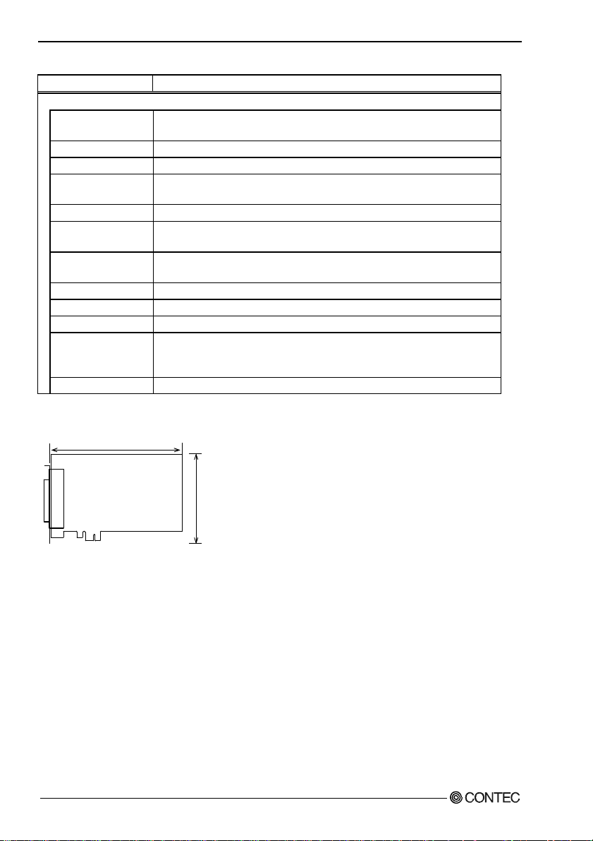
6. About Hardware
Table 6.1. Specification < DIO-6464L-PE > < 2 / 2 >
Item Specification
Common
Allowable distance of
signal extension
I/O address Any 32-byte boundary
Interruption level 1 level use
Max. board count for
connection
Isolated power
External circuit power
supply
Power consumption
(Max.)
Operating condition
Bus specification
Dimension (mm)
Connector 100 pin 0.8mm pitch connector [F (female) type] x 2
Weight
*1 Data "0" corresponds at the High level and data "1" correspond at the Low level.
Approx. 50m (depending on wiring environment)
16 boards including the master board
250Vrms
12 - 24VDC(±10%)
3.3VDC 600mA
0 - 50°C, 10 - 90%RH (No condensation)
PCI Express Base Specification Rev. 1.0a x1
169.33(L) x 110.18(H)
HDRA-E100W1LFDT1EC-SL+[HONDA TSUSHIN KOGYO CO., LTD.] or equivalent
to it
215g
Board Dimensions
169.33(L)
110. 18(H )
The standard outside dimension (L) is
the distance from the end of the board to
the outer surface of the slot cover.
DIO-6464L-PE, DI-128L-PE, DO-128L-PE
64
[mm]
Page 72

6. About Hardware
DI-128L-PE
Table 6.2. Specification < DI-128L-PE >
Item Specification
Input
Input format Optocoupler isolated input (Compatible with current sink output)(Negative logic *1)
Number of input
signal channels
Input resistance 4.7kΩ
Input ON current 2.0mA or more
Input OFF current 0.16mA or less
Interrupt 16 interrupt input signals are arranged into a single output of interrupt signal INTA.
128 channels (16 channels available for interrupts) (1 common per 16 channels unit)
An interrupt is generated at the rising edge (HIGH-to-LOW transition) or
falling edge (LOW-to-HIGH transition) (set by software).
Response time Within 200
Common
Allowable distance of
signal extension
I/O address Any 32-byte boundary
Interruption level 1 level use
Max. board count for
connection
Isolated Power 250Vrms
External circuit
power supply
Power consumption
(Max.)
Operating condition 0 - 50°C, 10 - 90%RH (No condensation)
Bus specification PCI Express Base Specification Rev. 1.0a x1
Dimension (mm) 169.33(L) x 110.18(H)
Connector 100 pin 0.8mm pitch connector [F (female) type] x 2
Weight 215g
*1 Data "0" corresponds at the High level and data "1" correspond at the Low level.
Approx. 50m (depending on wiring environment)
16 boards including the master board
12 - 24VDC(±10%)
3.3VDC 600mA
HDRA-E100W1LFDT1EC-SL+[HONDA TSUSHIN KOGYO CO., LTD.] or equivalent
to it
μsec
Board Dimensions
169.33(L)
110. 18(H )
The standard outside dimension (L) is
the distance from the end of the board to
the outer surface of the slot cover.
[mm]
DIO-6464L-PE, DI-128L-PE, DO-128L-PE
65
Page 73

6. About Hardware
DO-128L-PE
Table 6.3. Specification < DO-128L-PE >
Item Specification
Output
Output format Optocoupler isolated open-collector output (current sink type)(Negative logic *1)
Number of output signal
channels
rating
Residual voltage with
output on
Surge protector Zener diode RD47FM(NEC) or equivalent to it
Response time Within 200
Common
Allowable distance of
signal extension
I/O address Any 32-byte boundary
Interruption level Not used
Max. board count for
connection
Isolated Power 250Vrms
External circuit power
supply
Power consumption (Max.) 3.3VDC 600mA
Operating condition 0 - 50°C, 10 - 90%RH (No condensation)
Bus specification PCI Express Base Specification Rev. 1.0a x1
Dimension (mm) 176.41(L) x 106.68(H)
Connector 100 pin 0.8mm pitch connector [F (female) type] x 2
Weight 215g
*1 Data "0" corresponds at the High level and data "1" correspond at the Low level.
Output voltage 35VDC (Max.) Output
Output current 100mA (par 1
128 channels (1 common per 16 channels unit)
channel) (Max.)
0.5V or less (Output current≤50mA), 1.0V or less (Output current≤100mA)
μsec
Approx. 50m (depending on wiring environment)
16 boards including the master board
12 - 24VDC(±10%)
HDRA-E100W1LFDT1EC-SL+[HONDA TSUSHIN KOGYO CO., LTD.] or
equivalent to it
Board Dimensions
169.33(L)
110. 18(H )
The standard outside dimension (L) is
the distance from the end of the board to
the outer surface of the slot cover.
DIO-6464L-PE, DI-128L-PE, DO-128L-PE
66
[mm]
Page 74

6. About Hardware
Block Diagram
DIO-6464L-PE
External
digital input port0
(8 channels, group0)
External
digital input port1
(8 channels, group1)
External
digital input port2
(8 channels, group2)
External
Opto
coupler
Control
Circuits
PCI Express BUS
Opto
coupler
&
Interrupt
Control Circuit
Transistors
DIO-6464L-PE
Figure 6.1. Block Diagram < DIO-6464L-PE >
digital input port3
(8 channels, group3)
External
digital input port4
(8 channels, group4)
External
digital input port5
(8 channels, group5)
External
digital input port6
(8 channels, group6)
External
digital input port7
(8ch, group7)
External
digital output port0
(8 channels, group8)
External
digital output port1
(8 channels, group9)
External
digital output port2
(8 channels, groupA)
External
digital output port3
(8 channels, groupB)
External
digital output port4
(8 channels, groupC)
External
digital output port5
(8 channels, groupD)
External
digital output port6
(8 channels, groupE)
External
digital output port7
(8 channels, groupF)
DIO-6464L-PE, DI-128L-PE, DO-128L-PE
67
Page 75

6. About Hardware
DI-128L-PE
PCI Express BUS
Interrupt
Control Circuit
Control
Circuits
Opto
coupler
DI-128L-PE
External
digital input port0
(8 channels, group0)
External
digital input port1
(8 channels, group1)
External
digital input port2
(8 channels, group2)
External
digital input port3
(8 channels, group3)
External
digital input port4
(8 channels, group4)
External
digital input port5
(8 channels, group5)
External
digital input port6
(8 channels, group6)
External
digital input port7
(8 channels, group7)
External
digital input port8
(8 channels, group8)
External
digital input port9
(8 channels, group9)
External
digital input port A
(8 channels, groupA)
External
digital input port B
(8 channels, groupB)
External
digital input port C
(8 channels, groupC)
External
digital input port D
(8 channels, groupD)
External
digital input port E
(8 channels, groupE)
External
digital input port F
(8 channels, groupF)
Figure 6.2. Block Diagram < DI-128L-PE >
DIO-6464L-PE, DI-128L-PE, DO-128L-PE
68
Page 76

6. About Hardware
DO-128L-PE
External
digital output port0
(8 channels, group0)
External
digital output port1
(8 channels, group1)
External
digital output port2
(8 channels, group2)
External
digital output port3
(8 channels, group3)
External
digital output port4
(8 channels, group4)
External
digital output port5
(8 channels, group5)
External
digital output port6
Control
Circuits
PCI Express BUS
Opto
coupler
&
Transistors
DO-128L-PE
(8 channels, group6)
External
digital output port7
(8 channels, group7)
External
digital output port8
(8 channels, group8)
External
digital output port9
(8 channels, group9)
External
digital output port A
(8 channels, groupA)
External
digital output port B
(8 channels, groupB)
External
digital output port C
(8 channels, groupC)
External
digital output port D
(8 channels, groupD)
External
digital output port E
(8 channels, groupE)
External
digital output port F
(8 channels, groupF)
Figure 6.3. Block Diagram < DO-128L-PE >
DIO-6464L-PE, DI-128L-PE, DO-128L-PE
69
Page 77

DIO-6464L-PE
DI-128L-PE
DO-128L-PE
User’s Guide
CONTEC CO., LTD. January 2009 Edition
3-9-31, Himesato, Nishiyodogawa-ku, Osaka 555-0025, Japan
Japanese http://www.contec.co.jp/
English http://www.contec.com/
Chinese http://www.contec.com.cn/
No part of this document may be copied or reproduced in any form by any means without prior written
consent of CONTEC CO., LTD. [01062009]
[10232006] Management No. A-51-324
[01062009_rev3] Parts No. LYGS083
 Loading...