

Page 1

PC-HELPER
Bi-Directional Digital I/O
Board for PCI Express
Low Profile
DIO-96D-LPE
User’s Guide
CONTEC CO.,LTD.
Page 2
Check Your Package
Thank you for purchasing the CONTEC product.
The product consists of the items listed below.
Check, with the following l ist, that yo ur package is c omplete. If y ou discover dam aged or m issing item s,
contact your retailer.
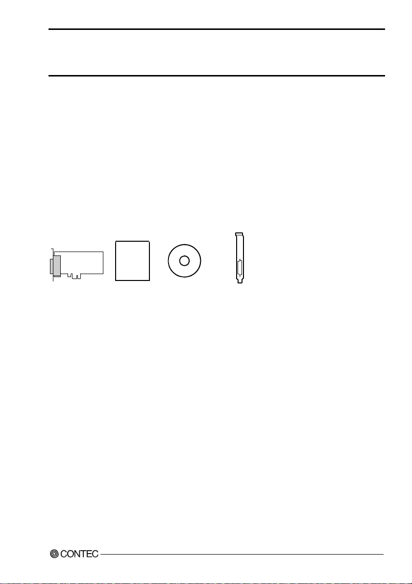
Product Configuration List
- Board [DIO-96D-LPE] …1
- First step guide …1
- CD-ROM *1 [API-PAC(W32)] …1
- Standard size bracket …1
*1 The CD-ROM contains the driver software and User’s Guide (this guide)
Board
DIO-96D-LPE
First step guide
CD-ROM
[API-PAC(W32)]
Standard-sized bracket
i
Page 3

Copyright
Copyright 2008 CONTEC CO., LTD. ALL RIGHTS RESERVED
No part of this document may be copied or reproduced in any form by any means without prior written
consent of CONTEC CO., LTD.
CONTEC CO., LTD. makes no commitment to update or keep current the information contained in this
document. The information in this document is subject to change without notice.
All relevant issues have been considered in the preparation of this document. Should you notice an
omission or any questionable item in this document, please feel free to notify CONTEC CO., LTD.
Regardless of the foregoing statement, CONTEC assumes no responsibility for any errors that may
appear in this document nor for results obtained by the user as a result of using this product.
Trademarks
MS, Microsoft and Windows are trademarks of Microsoft Corporation. Other brand and product names
are trademarks of their respective holder.
DIO-96D-LPE
ii
Page 4

Table of Contents
Check Your Packag e............................................................................................................................ i
Copyright ............................................................................................................................................ ii
Trademarks .........................................................................................................................................ii
Table of Con tents...............................................................................................................................ii i
1. BEFORE USING THE PRODUCT 1
About the Bo ard.................................................................................................................................. 1
Features........................................................................................................................................ 1
Support Softw ar e ......................................................................................................................... 2
Cable & Connect o r (Op t ion ) ...................................................................................................... 3
Accessories ( Op ti on ) .................................................................................................................. 3
Customer Supp o rt ............................................................................................................................... 4
Web Site....................................................................................................................................... 4
Limited Thre e- Y ea rs Wa rr a n ty .......................................................................................................... 4
How to Obtain Serv i ce ....................................................................................................................... 4
Liability............................................................................................................................................... 4
Safety Precau t io ns .............................................................................................................................. 5
Safety Infor mat i o n ....................................................................................................................... 5
Handling Pre ca u tio ns................................................................................................................... 6
Environment................................................................................................................................. 7
Inspection..................................................................................................................................... 7
Storage ......................................................................................................................................... 7
Disposal ....................................................................................................................................... 7
2. SETUP 9
What is Setup? .................................................................................................................................... 9
Using the Board und er Wi nd o ws Us ing th e Dr iv er Li b ra ry AP I- P AC( W 32 ) ............................ 9
Using the Board under Windows Using Software Other than the Driver Library
API-PAC(W32 ) ................................................................................................................... ......... 9
Using the Board under an OS Other than Windows ................................................................. 10
Step 1 Installi ng t he Software .......................................................................................................... 11
About the driv e r to b e u s ed ....................................................................................................... 11
Starting the I ns t all P rog r a m....................................................................................................... 12
When Using API -D IO ( WD M)................................................................................................... 13
When Using API -D IO (9 8/ P C )................................................................................................... 14
Step 2 Setting th e H a rd wa r e ............................................................................................................. 16
Replacing the B ra ck e t................................................................................................................ 16
Parts of the Bo ard an d Fa c to ry Defaults ................................................................................... 17
Setting the Bo a rd ID .................................................................................................................. 17
Plugging th e Board .................................................................................................................... 18
DIO-96D-LPE
iii
Page 5

Step 3 Installi ng t h e H a rd wa re .........................................................................................................19
Turning on the PC...................................................................................................................... 19
When Using API -D IO ( WD M)................................................................................................... 19
When Using API -D IO (9 8/ P C )................................................................................................... 22
Step 4 Initial iz in g th e Sof t wa re ........................................................................................................ 25
When Using API -D IO ( WD M)................................................................................................... 25
When Using API -D IO (9 8/ P C )................................................................................................... 27
Updating the S e tt in gs................................................................................................................. 27
Step 5 Checkin g Operations w i th th e Dia g no si s P rog r a m ............................................................... 28
What is the Di agn o sis P ro g ra m? ............................................................................................... 28
Check Method ............................................................................................................................28
Using the Di agnosis Prog ram....................................................................................................29
Setup Troubl esh o ot in g...................................................................................................................... 33
Symptoms and A cti on s .............................................................................................................. 33
If your proble m c an n ot b e reso lv ed...........................................................................................3 3
3. EXTERNAL CONNECTION 35
Using the On-board Conn e c t ors ....................................................................................................... 35
Connecting a Device to a Con n ec to r ......................................................................................... 35
Connector Pin As si gnment ........................................................................................................ 36
Relationships be t we en AP I-P AC ( W32 ) Log ic a l Po rt s/B i ts and Co nn e cto r Sig na l P in s..........38
Connecting I/ O Sig na l s..................................................................................................................... 39
I/O Circuit .................................................................................................................................. 39
Example Conn ect i on 1 (Us in g PC A6 8 P S-* * P)......................................................................... 40
Example Conn ect i on 2 (Us in g D IO - 68 M/ 96 F ) ......................................................................... 40
Surge Protect io n................................................................................................................................ 41
4. FUNCTION 43
Data I/O Func tio n ............................................................................................................................. 43
I/O setup of the port...................................................................................................................4 3
Data I/O...................................................................................................................................... 45
Digital Filter Function ...................................................................................................................... 46
Digital Filter Function Principle................................................................................................ 46
Set Digital F il te r T i me ............................................................................................................... 46
Interrupt Con t ro l Fu n ct io n................................................................................................................ 47
Disabling/en ab l in g I nt e rr up ts ....................................................................................................47
Selecting the edg e of in pu t s ign als , at wh ic h to gen e ra t e an in ter ru p t ...................................... 47
Clearing the Inte rru pt St atu s an d In t e rru p t S ig n al .................................................................... 47
DIO-96D-LPE
iv
Page 6

5. ABOUT SOFTWARE 49
CD-ROM Directo r y S t ru c tu re .......................................................................................................... 49
About Softw a r e for Windows..................................................................................................... ...... 50
Accessing th e Help File............................................................................................................. 50
Using Sample Programs ............................................................................................................ 50
Uninstalling the D riv e r L ib r ar ies .............................................................................................. 52
About Softw a r e for Linux ....................................................................................................... .......... 55
Driver Softwa re In st al l P roc edu r e ............................................................................................. 55
Accessing th e Help File............................................................................................................. 56
Using Sample Programs ............................................................................................................ 56
Uninstalling the driver............................................................................................................... 56
6. ABOUT HARDWARE 57
For detailed t e chn i cal in fo r ma tio n ................................................................................................... 57
Hardware spe cification ..................................................................................................................... 57
Block Diagra m.................................................................................................................................. 58
Difference f rom DIO-96 D2-LPCI.................................................................................................. .. 59
DIO-96D-LPE
v
Page 7

DIO-96D-LPE
vi
Page 8

1. Before Using the Product
1. Before Using the Product
This chapter provides information you should know before using the product.
About the Board
This product is a PCI Express bus-compliant interface board that extends the input/output function of
bi-directional digital signal. This board has up to 96 unisolated LVTTL-level input/output channels that
is powered by the equivalence to the mode 0 of i8255 chips, and you can use up to 96 channels of the
input signals as interrupt inputs. You can select the input/output by the application software in eight
signals units (in four signals unit f or some inputs/outputs). Additionally, the digital filter function is
equipped with this product. Windows/Linux driver is bundled with this product.
Using the dedicated library VI-DAQ makes it possible to create each application for LabVIEW.
Features
- This board can be used to input/output 96 points bi-directional digital corresponding to to the
equivalence to the i8255 mode 0.
This board has up to 96 unisolated LVTTL-level input/output channels whose response speed is
200μsec that is powered by to the equivalence to the mode 0 of i8255 device for general-purpose.
You can select the input/outp ut by the ap plication software i n eight sig nals unit s (in four signals unit
for some inputs/outputs).
- You can use up to 96channels of the input signals as interrupt events.
You can use up to 96channels of the input signals as interrupt events and also disable or enable the
interrupt in bit units and select the edge of signals, at which to generate an interrupt.
- This product has a digital filter function to prevent wrong recognition of in put signa ls fr om carryi ng
noise or a chattering.
This product has a digital filter function to prevent wrong recognition of input signals by noise or
chattering is provided. All input terminals can be added a digital filter, and the setting can be
performed by software.
- Windows/Linux compatible driver libraries are attached.
Using the attached driver library API-PAC(W32) makes it possible to create applications of
Windows/Linux. In addition, a diagnostic program by which the operations of hardware can be
checked is provided.
- Support for both of Low Profile and standard size slots
Support for both of Low Profile and standard size slots (interchangeable with a bundled bracket).
- Functions and connectors are compatible with PCI compatible board DIO-96D2-LPCI.
The functions same with PCI com patible boar d DI O-9 6D2- LPCI are pr ovi de d. I n a dditi o n, a s t here
is compatibility in terms of connector shape and pin assignments, it is easy to migrate from the
existing system.
- LabVIEW is supported by a plug-in of dedicated library VI-DAQ.
Using the dedicated library VI-DAQ makes it possible to create each application for LabVIEW.
DIO-96D-LPE
1
Page 9

1. Before Using the Product
Support Software
You should use CONTEC support software accor d ing to your purpose and development environment.
Windows version of digital I/O driver
API-DIO(98/PC) / API-DIO(WDM)
[Stored on the bundled CD-ROM driver library API-PAC(W32)]
The API-DIO(98/PC) is the Windows version driver library software that provides products in the form of Win32 API
functions (DLL). Various sample programms such as Visual Basic and Visual C++, etc and diagnostic program useful
for checking operation is provided.
< Operating environment >
OS Windows Vista, XP, Server 2003, 2000
Adaptation language Visual Basic, Visual C++, Visual C#, Delphi, C++ Builder
You can download the updated version from the CONTEC’s Web site (http://www.contec.com/apipac/). For more
details on the supported OS, applicable language and new information, please visit the CONTEC’s Web site.
Linux version of digital I/O driver
API-DIO(LNX)
[Stored on the bundled CD-ROM driver library API-PAC(W32)]
The API-DIO(LNX) is the Linux version driver software which provides device drivers (modules) by shared library
and kernel version. Various sample programs of gcc are provided.
< Operating environment >
OS RedHatLinux, TurboLinux
(For details on supported distributions, refer to Help availabl e after installation .)
Adaptation language gcc
You can download the updated version from the CONTEC’s Web site (http://www.contec.com/apipac/). For more
details on the supported OS, applicable language and new information, please visit the CONTEC’s Web site.
Data acquisition VI library for LabVIEW
(Available for downloading (free of charge) from
VI-DAQ
the CONTEC web site.)
This is a VI library to use in National Instruments LabVIEW.
VI-DAQ is created with a function form similar to that of LabVIEW's Data Acquisition VI, allowing you to use various
devices without complicated settings.
See http://www.contec.com/vidaq/ for details and download of VI-DAQ.
DIO-96D-LPE
2
Page 10

1. Before Using the Product
Cable & Connector (Option)
Cable with 68-Pin D-sub Connector at either Ends (Mold Type)
: PCB68PS-0.5P (0.5m)
: PCB68PS-1.5P (1.5m)
Shield Cable with One 68-Pin Connector
: PCA68PS-0.5P (0.5m)
: PCA68PS-1.5P (1.5m)
Shielded Cable for CardBusDigital I/O Card
: DIO-68M/96F (0.5m)
* If using both the CNA and CNB connectors, two cable sets are required.
Accessories (Option)
Screw Terminal Unit (M3 x 68P) : EPD-68A *1*3
Screw Terminal Unit (M3 x 96P) : EPD-96A *2*3
Screw Terminal Unit (M3.5 x 96P) : EPD-96 *2
Terminal Unit for Cables (M3 x 96P) : DTP-64A *2
*1 PCB68PS-0.5P or PCB68PS-1.5P optional cable is required separately.
*2 DIO-68M/96F optional cable is required separately.
*3 “Spring-up” type terminal is used to prevent terminal screws from falling off.
*4 If using both the CNA and CNB connectors, two each of the accessories and cable set s are required.
* Check the CONTEC’s Web site for more information on these options.
DIO-96D-LPE
3
Page 11

1. Before Using the Product
Customer Support
CONTEC provides the following s upport services fo r you to use CONTEC products more efficiently and
comfortably.
Web Site
Japanese http://www.contec.co.jp/
English http://www.contec.com/
Chinese http://www.contec.com.cn/
Latest product information
CONTEC provides up-to-date information on products.
CONTEC also provides product manuals and various technical documents in the PDF.
Free download
You can download updated driver software a nd diff erenti al files as we ll as sample pr ograms available i n
several languages.
Note! For product information
Contact your retailer if you have any technical question about a CONTEC product or need its price,
delivery time, or estimate information.
Limited Three-Years Warranty
CONTEC products are warranted by CONTEC CO., LTD. to be free from defects in material and
workmanship for up to three years from the date of purchase by the original purchaser.
Repair will be free of char ge only w hen thi s device is ret urned fr eight pr epaid with a c opy of the origi nal
invoice and a Return Merchandise Authorization to the distributor or the CONTEC group office, from
which it was purchased.
This warranty is not applicable for scratches or normal wear, but only for the electronic circuitry and
original boards. The warranty is not applicabl e if the device has been tamper ed with or damaged t hrough
abuse, mistreatment, neglect, or unreasonable use, or if the original invoice is not included, in which case
repairs will be considered beyond the warranty policy.
How to Obtain Service
For replacement or repair, return the device freight prepaid, with a copy of the original invoice. Please
obtain a Return Merchandise Authorization Number (RMA) from the CONTEC group office where you
purchased before returning any product.
* No product will be accepted by CONTEC group without the RMA number.
Liability
The obligation of the warrantor is solely to repair or replace the product. In no event will the warrantor
be liable for any incidental or consequential damages due to s uch defec t or consequence s that arise from
inexperienced usage, misuse, or malfunction of this device.
DIO-96D-LPE
4
Page 12

1. Before Using the Product
Safety Precautions
Understand the following definitions and precautions to use the product safely.
Safety Information
This document provides safety information u sing the foll owing sym bols to prevent a ccidents res ulting in
injury or death and the destruc tion of equi pment and res ources. Under stand the mean ings of these la bels
to operate the equipment safely.
DANGER
WAR NI NG
CAUTION
DANGER indicates an imminently hazardous situation which, if not avoided, will
result in death or serious injury.
WARNING indicates a potentially hazardous situation which, if not avoided, could
result in death or serious injury.
CAUTION indicates a potentially hazardous situation which, if not avoided, may
result in minor or moderate injury or in property damage.
DIO-96D-LPE
5
Page 13

1. Before Using the Product
Handling Precautions
DANGER
Do not use the product where it is exp osed t o flamm able or c orros ive ga s. Doin g so m ay result in an
explosion, fire, electric shock, or failure.
CAUTION
- There is a switch on the board that needs to be set in advance.
Be sure to check these before installing the board.
- Only set the switche s and ju mpe rs on th e bo a rd to th e sp ec if ied set ting s .
Otherwise, the board may malfunction, overheat, or cause a failure.
- Do not strike or bend the board. Doing so could damage the board.
Otherwise, the board may malfunction, overheat, cause a failure or breakage.
- Do not touch the board's metal plated terminals (edge connector) with your hands.
Otherwise, the board may malfunction, overheat, or cause a failure.
If the terminals are touched by someone's hands, clean the terminals with industrial alcohol.
- Do not install or remove the board to or from the slot while the computer's power is turned on.
Otherwise, the board may malfunction, overheat, or cause a failure.
Doing so could cause trouble. Be sure t hat the pe rson al com puter or t he I/O e xpan sion unit pow er is
turned off.
- Make sure that your PC or expansion unit can supply ample power to all the boards installed.
Insufficiently energized boards could malfunction, overheat, or cause a failure.
- The specifications of this product are subject to change without notice for enhancement and quality
improvement.
Even when using the product continuously, be sure to read the manual and understand the contents.
- Do not modify the product. CONTEC will bear no responsibility for any problems, etc., resulting
from modifying this product.
- Regardless of the foregoing statements, CONTEC is not liable for any damages whatsoever
(including damages for loss of business profits) arising out of the use or inability to use this
CONTEC product or the information contained herein.
DIO-96D-LPE
6
Page 14
1. Before Using the Product
Environment
Use this product in the following environment. If used in an unauthorized environment, the board may
overheat, malfunction, or cause a failure.
Operating temperature
0 - 50°C
Operating humidity
10 - 90%RH (No condensation)
Corrosive gases
None
Floating dust particles
Not to be excessive
Inspection
Inspect the product periodically as follows to use it safely.
- Check that the bus connector
of the board and its cable have
been plugged correctly.
- Check that the board has
no dust or foreign matter adhering.
- The gold-plated leads of the bus connector
have no stain or corrosion.
Storage
When storing this product, keep it in its original pa cking form.
(1) Put the board in the storage bag.
(2) Wrap it in the packing material, then put it in the box.
(3) Store the package at room temperature at a place free from direct sunlight, moisture, shock,
vibration, magnetism, and static electricity.
Disposal
When disposing of the product, follow the disposal procedures stipulated under the relevant laws and
municipal ordinances.
DIO-96D-LPE
7
Page 15

1. Before Using the Product
DIO-96D-LPE
8
Page 16

2. Setup
2. Setup
This chapter explains how to set up the board.
What is Setup?
Setup means a series of steps to take before the product can be used.
Different steps are required for software and hardware.
The setup procedure varies with the OS and applications used.
Using the Board under Windows
Using the Driver Library API-PAC(W32)
This section describes the setup procedure to be performed before you can start developing application
programs for the board using the bundled CD-ROM “Driver Library API-PAC(W32)”.
Taking the following steps sets up the software and hardware. You can use the diagnosis program later
to check whether the software and hardware function normally.
Step 1 Installing the Software
Step 2 Setting the Hardware
Step 3 Installing the Hardware
Step 4 Initializing the Software
Step 5 Checking Operations with the Diagnosis Program
If Setup fails to be performed normally, see the “Setup Troubleshooting” section at the end of this
chapter.
Using the Board under Windows
Using Software Other than the Driver Library API-PAC(W32)
For setting up software other than API-PAC(W32), refer to the user’s guide for that software. See also
the following parts of this u se r’s gu i de as requ ir ed.
This chapter Step 2 Setting the Hardware
This chapter Step 3 Installing the Hardware
Chapter 3 External Connection
Chapter 6 About Hardware
DIO-96D-LPE
9
Page 17

2. Setup
Using the Board under an OS Other than Windows
For using the board under Linux, see the following parts of this user’s guide.
This chapter Step 2 Setting the Hardware
Chapter 3 External Connection
Chapter 5 About Software
Chapter 6 About Hardware
For using the board under an OS such as MS-DOS other than Windows, see the following parts of this
user’s guide.
This chapter Step 2 Setting the Hardware
Chapter 3 External Connection
Chapter 6 About Hardware
DIO-96D-LPE
10
Page 18
2. Setup
Step 1 Installing the Software
This section describes how to install the Driver libraries.
Before installing the hardware on your PC, install the Driver libraries from the bundled API-PAC(W32)
CD-ROM.
The following description assumes the operating system as Windows XP. Although some user
interfaces are different depending on the OS used, the basic procedure is the same.
About the driver to be used
Two digital I/O drivers are available : API-DIO(WDM) and API-DIO(98/PC).
API-DIO(WDM) is a new driver to perform digital I/O under Windows.
API-DIO(WDM) was developed to improve the conventional product version of API-DIO(98 /PC) in the
ease of use and functionality.
It is advisable to use API-DIO(WDM) for you to use an digital I/O device. API-DIO(WDM) will
support new OS and devices in the future but will not support Windows NT 4.0, Windows 95, ISA bus.
Use API-DIO(98/PC) if your operating environment contains such an unsupported piece of software or
hardware.
Check the following sele ct ion gu ide to eas il y se le ct th e driv e r to be us ed.
OS to be used
Windows Vista
Windows XP/Windows 2000
PCI bus, PC Card
Use the digital board for
the first time?
Ye s
Language to be used
VC.Net, VB.Net, VC#.Net
VC6, VB6
API-DIO(WDM)
DIO-96D-LPE
Device type
Windows Me/98/95
Windows NT 4.0
ISA Bus
Already used.
The existing system
upgrade using
API-DIO(98/PC)?
No
VC2, 4, 5, VB4, 5,
Delphi, C++Builder
Ye s
API-DIO(98/PC)
11
Page 19
2. Setup
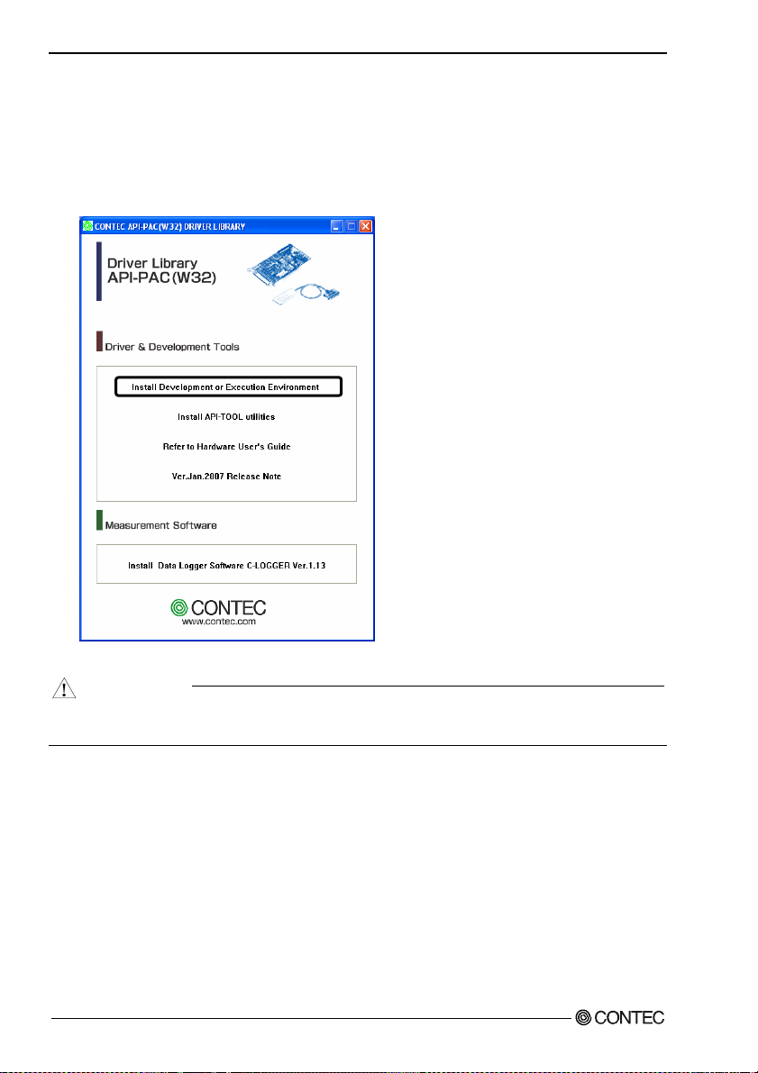
Starting the Install Program
(1)
Load the CD-ROM [API-PAC(W32)] on your PC.
(2)
The API-PAC(W32) Installer window appears automatically.
If the panel does not appear, run (CD-ROM drive letter):\AUTORUN.exe.
(3)
Click on the [Install Development or Execution Environment] button.
* When using the Windows Vista, driver is automatically installed.
CAUTION
Before installing the software in Windows Vista, XP, Server 2003, 2000 and NT, log in as a user
with administrator privileges.
DIO-96D-LPE
12
Page 20
2. Setup
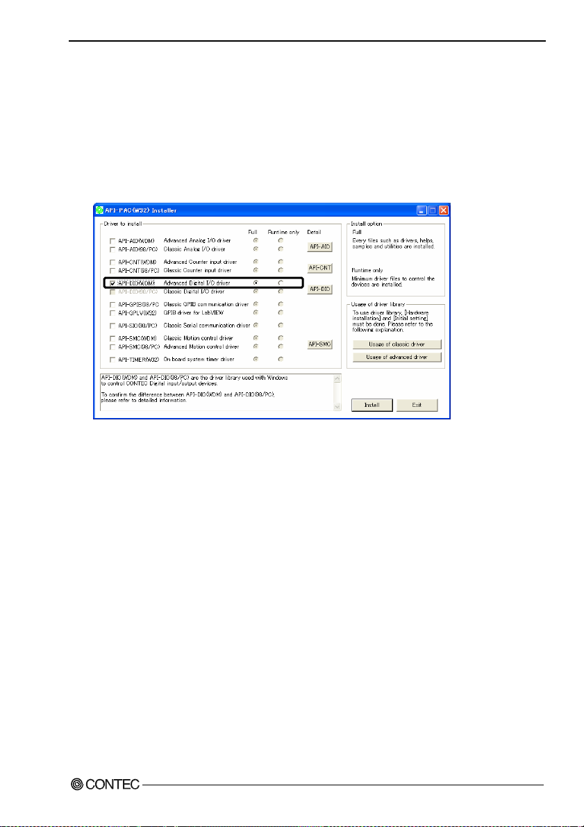
When Using API-DIO(WDM)
Selecting API-DIO(WDM)
(1)
The following dialog box appears to select “Driver to install” and “Install option”, “Usage of
driver library”.
(2)
Select the "Advanced Digital I/O driver".
(3)
Click on the [Install] button.
* Clicking the [API-DIO] button displays d etailed information about API-DIO(WDM) and
API-DIO(98/PC).
Run the installation
(1)
Complete the installation by following the instructions on the screen.
(2)
The Readme file appears when the installation is complete.
DIO-96D-LPE
13
Page 21
2. Setup
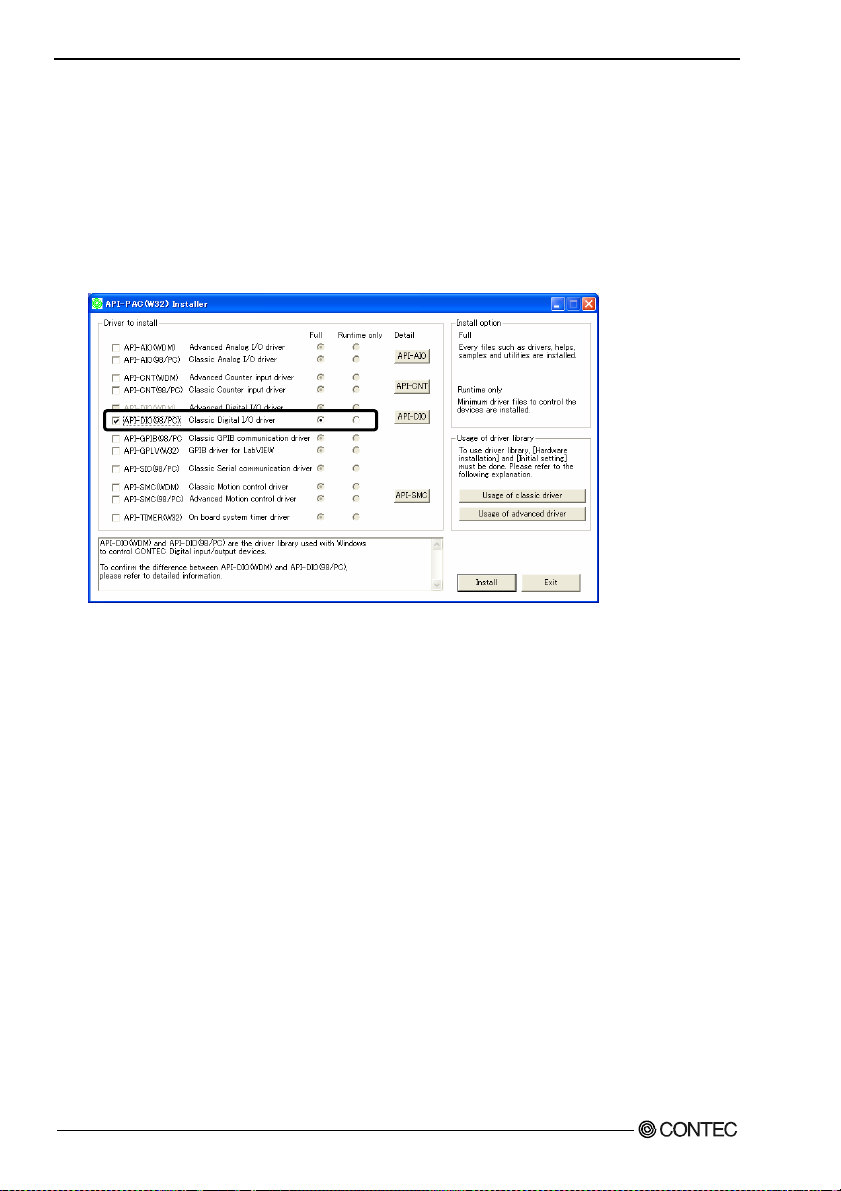
When U sin g API-DIO(98/PC)
Selecting API-DIO(98/PC)
(1)
The following dialog box appears to select “Driver to install” and “Install option”, “Usage of
driver library”.
(2)
Select “Classic Digital I/O driver”.
(3)
Click on the [Install] button.
* Clicking on the [API-DIO] button displays detailed information on API-DIO(WDM),
API-DIO(98/PC).
DIO-96D-LPE
14
Page 22

2. Setup
Executing the Installation
(1)
Follow the on-screen instructions to proceed to install.
(2) When the required files have been copied, the “Perform a hardware setup now(API-TOOL
Configuration)” and “Show readme file” check boxes are displayed.
When you are installing the software or hardware for the first time:
1) Uncheck “Perform a hardware setup now”.
2) Click on the [Finish] button.
Go to Step 2 to set and plug the hardware.
* When the hardware has already been installed:
Check “Perform a hardware setup now(API-TOOL Configuration)”, then go to Step 4
“Initializing the Software”.
You have now finished installing the software.
DIO-96D-LPE
15
Page 23

2. Setup
Step 2 Setting the Hardware
This section describes how to set the board and plug it on your PC.
The board has some switches and jumper to be preset.
Check the on-board switches and jumpers before plugging the board into an expansion slot.
The board can be set up even with the factory defaults untouched. You can change board settings later.
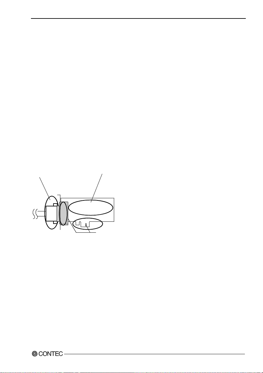
Replacing the Bracket
This product is shipped with a Low Profile size bracket mounted. To plug the product into a standard
size slot, replace the bracket with the bundled standard-sized bracket. The replacing method is as
follows :
Standard-sized bracket
- Remove the screws and replace it
with the Standard-sized bracket.
Low Profile size bracket
Screw
Use a flathead screwdriver or hexagonal spanner to undo and tighten the screws.
Figure 2.1. Replacing the Bracket
DIO-96D-LPE
16
Page 24

2. Setup
Parts of the Board and Factory Defaults
Figure 2.2. shows the names of major parts on the board.
Note that the switch setting shown below is the factory default.
- Interface connector
(CNA, CNB)
Figure 2.2. Component Locations
SW1
BOARD ID
- Board ID setting switch
(SW1)
SW1
BOARD ID
8
9
7
6
5
4
3
2
1
0
A
B
C
D
E
F
Setting the Board ID
If you install two or more boards on one personal computer, assign a different ID value to each of the
boards to distinguish them.
The board IDs can be set from 0 - Fh to identify up to sixteen boards.
If only one board is used, the original factory setting (Board ID = 0) should be used.
Setting Procedure
To set the board ID, use the rotary switch on the boar d. Tur n the SW 1 knob to set the board ID a s show n
below.
SW1
BOARD ID
8
9
7
A
6
B
5
C
4
D
0
1
E
F
Factory setting:
(Board ID = 0)
3
2
Figure 2.3. Board ID Settings (SW1)
DIO-96D-LPE
17
Page 25

2. Setup
Plugging the Board
(1) Before plugging the board, shut down th e syste m, unplug the power code of you r PC.
(2) Remove the cover from the PC so that the board can be mounted.
(3) Plug the board into an expansion slot.
(4) Attach the board bracket to the PC with a screw.
(5) Put the cover back into place.
CAUTION
- Do not touch the board's metal plated terminals (edge connector) with your hands.
Otherwise, the board may malfunction, overheat, or cause a failure.
If the terminals are touched by someone's hands, clean the terminals with industrial alcohol.
- Do not install or remove the board to or from the slot while the computer's or expansion unit’s power is
turned on.
Otherwise, the board may malfunction, overheat, or cause a failure.
Be sure that the personal computer power is turned off.
- Make sure that your PC or expansion unit can supply ample power to all the boards installed.
Insufficiently energized boards could malfunction, overheat, or cause a failure.
DIO-96D-LPE
18
Page 26

2. Setup
Step 3 Installing the Hardware
For using an expansion board under Windows, y ou have t o let the OS detect the I /O addresses and IRQ to
be used by the board. The process is referred to as installing the hardware.
In the case of using two or more boar ds, make sur e you install one by one with the F ound New Hardware
Wizard.
Turning on the PC
Turn on the power to your PC.
CAUTION
- The board cannot be properly installed unless the resources (I/O addresses and interrupt level) for
the board can be allocated. Before attempting to install the board, first determ ine what PC resource s
are free to use.
- The resources used by each board do not depend on the location of the PCI Express bus slot or the
board itself. If you remove two or more boards that have already been installed and then remount
one of them on the computer, it is unknown that which one of the sets of res ources previous ly
assigned to the two bo ards is assi gned to th e re moun ted bo ard . In th is c ase , you mus t ch e ck th e
resource settings.
When Using API-DIO(WDM)
(1) The “Found New Hardware Wizard” will be started.
Select “No, not this time” and then click the “Next” button.
DIO-96D-LPE
19
Page 27

2. Setup
(2) When “Multimedia Controller” is displayed, select “Install from a list or s
location[Advanced]” and then specify that folder on the CD-ROM which contains the setup
information (INF) file to register the board.
When the model name of hardware is displayed, select “Install the software automatically
[Recommended]” and then click on the “Next” button.
Source folder
The setup information (INF) file is contained in the following folder on the bundled CD-ROM.
Windows Vista, XP, Server 2003, 2000 \INF\Wdm\Dio
pecific
\INF\Wdm\Dio
DIO-96D-LPE
20
Page 28

2. Setup
* The name of the board
you have just added is
displayed.
- DIO-96D-LPE
You have now finished installing the hardware.
DIO-96D-LPE
21
Page 29

2. Setup
When Using API-DIO(98/PC)
(1) The “Found New Hardware Wizard” will be started.
Select “No, not this time” and then click the “Next” button.
(2) Select “Install from a list or s
pecific location[Advanced]” and then click the “Next” button.
DIO-96D-LPE
22
Page 30

2. Setup
(3) Specify that folder on the CD-ROM which contains the setup information (INF) file to register the
board.
* The name of the board
you have just added is
displayed.
- DIO-96D-LPE
Source folder
The setup information (INF) file is contained in the following folder on the bundled CD-ROM.
Windows Vista, XP, Server 2003, 2000 \INF\Win2000\Dio\PCI
Example of specifying the folder for use under Windows XP
DIO-96D-LPE
\INF\Win2000\Dio\PCI
23
Page 31

2. Setup
CAUTION
In Windows XP, the Hardware Wizard displays the following alert dialog box when you have
located the INF file. This dialog box appears, only indicating that the releva nt dr iver has not passe d
Windows Logo testing, an d it ca n be i gnored without developing any prob lem wit h t he oper a ti on of
the board.
In this case, click on the [Continue Anyway] button.
You have now finished installing the hardware.
* The name of the board
you have just added is
displayed.
- DIO-96D-LPE
DIO-96D-LPE
24
Page 32

2. Setup
Step 4 Initializing the Software
The driver library requires the initial setting to recognize the execution environment. It is called the
initialization of the Driver library.
When U sin g API-DIO(WDM)
API-DIO(WDM) is initialized automatically during hardware installation. Therefore, if you want to use
it with its initial settings, you can skip the setting procedure described in Step 4. To change the device
name, follow the setting procedure shown below.
Setting the device name
(1) Run Device Manager. From [My Computer] - [Control Panel], select [System] and then select the
[Device Manager] tab.
(You can also open Device Manager by right clicking on My Computer and selecting Properties.)
* The name of the board
you have just added is
displayed.
- DIO-96D-LPE
(2) The installed hardware appears under the CONTEC Devices node. Open the CONTEC Devices
node and select the device you want to setup (the device name should appear highlighted). Click
[Properties].
DIO-96D-LPE
25
Page 33

2. Setup
(3) The property page for the device opens.
Enter the device name in the common settings tab page and then click [OK].
The device name you set here is used later when programming.
* The initial device name that appears is a default value. You can use this default name if you wish.
* Make sure that you do not use the same name for more than one device.
You have now finished installing the initial setting of Software.
DIO-96D-LPE
26
Page 34

2. Setup
When U sin g API-DIO(98/PC)
(1) Open the Start Menu, then select “Programs” – “CONTEC API-PAC(W32)” – “API-TOOL
Configuration”.
(2) API-TOOL Configuration detects boards automatically.
The detected boards are listed.
Updating the Settings
(1) Select “Save setting to registry…” from the “File” menu.
You have now finished installing the initial setting of Software.
DIO-96D-LPE
27
Page 35

2. Setup
Step 5 Checking Operations with the Diagnosis Program
Use the diagnosis program to check that the board and driver software work normally, thereby you can
confirm that they have been set up correctly.
What is the Diagnosis Program?
The diagnosis program diagnoses the states of the board and driver software.
It can also be used as a si mple ch ec k er when an ex t ern al dev i ce i s actu all y co nn ect ed .
Using the “Diagnosis Report” feature reports the driver settings, the presence or absence of the board,
I/O status, and interrupt status.
Check Method
Connect the board to a remote device to text the input/output and check the execution environment.
To connect the external device, see Chapter 3 “External Connection”.
DIO-96D-LPE
28
Page 36

2. Setup
Using the Diagnosis Program
Starting the Diagnosis Program for Use of API-DIO(WDM)
Click the [Diagnosis] button on the device property page to start the di agnosis progra m.
DIO-96D-LPE
29
Page 37

2. Setup
Startin g the Di a g n o s i s Progra m f or Use of API-DIO(98/PC)
Select the board in the API-TOOL Configuration windows, then run the Diagnosis Program. Follow the
instructions on screen.
* The name of the board you have just added is displayed.
* The name of the board
you have just added is
displayed.
- DIO-96D-LPE
DIO-96D-LPE
30
Page 38

2. Setup
Checking Digital Inputs and Outputs
The main panel of the Diagnosis Program appears.
You can check the current operation states of the board in the following boxes:
“Input Port” : Displays input values bit by bit at fixed time intervals.
“Output Port” : Mouse operation allows the data to output or display.
“Interrupt” : Displays the number of interrupts detected bit by bit.
* The name of the board
you have just added is
displayed.
- DIO-96D-LPE
To use the wait time control feature, click on t he [W ait C onfiguration] button. U se t he feat ure w hen t he
wait time based on the DioWait or DioWaitEx function is not normal.
To use the function executi on time measurem ent feature, click on t he [Measurem ent Time] button. Enter
the I/O start port and the number of ports, then press the measurement button. The time for each
execution of a function will be measured.
DIO-96D-LPE
31
Page 39

2. Setup
Diagnosis Report
(1) Clicking on the [Show Diagnos is Repo rt] button displays detailed da ta such as bo ard settin gs and
the diagnosis results while saving them in text format.
When it is API-DIO(WDM), file name to save the result is displayed.
When it is API-DIO(98/PC), the result is saved to the folder in wh i ch to in sta ll (Prog ra m
Files\CONTEC\API-PAC(W32)) by the text file (DioRep.txt) an d t h en displa ye d.
The Diagnosis Program performs “board presence/absence check”, “driver file test”, “board setting
test”, and so on.
CAUTION
Before executing diagnosis report output, unplug the cable from the board.
* The name of the board
you have just added is
displayed.
- DIO-96D-LPE
Click on [Show
(2) A diagnosis report is displayed as shown below.
* The name of the board
you have just added is
displayed.
- DIO-96D-LPE
DIO-96D-LPE
32
Diagnosis Report].
Page 40

2. Setup
Setup Troubleshooting
Symptoms and Actions
No output can be obtained.
Use API-TOOL Configuration to check whether the board name setting is wrong.
The board works with the Diagnosis Program but not with an application.
The Diagnosis Program is coded with API-TOOL functions. As long as the board operates with the
Diagnosis Program, it is to operate with other applications as well. In such cases, review your program
while paying attention to the following points:
- Check the arguments to functions and their return values.
- When the board is an isolated type, it has a time lag for its response between the output by a function
and the actual output. Consider the execution intervals between functions.
The OS won’t normally get started or detect the board.
[Windows Vista, Windows XP, Server 2003, 2000]
Turn off the power to your PC, then unplug the board. Restart th e OS and delete the board setting s of
API-TOOL Configuration. Turn off the PC ag ai n, pl ug the board, a nd res tart the OS. Let the OS detect
the board and use API-TOOL Configuration to register board settings.
If your problem cannot be resolved
Contact your retailer.
DIO-96D-LPE
33
Page 41

2. Setup
DIO-96D-LPE
34
Page 42

3. External Connection
3. External Connection
This chapter describes the interface connectors on the board and the external I/O circuits.
Check the information available here when connecting an external device.
Using the On-board Connectors
Connecting a Device to a Connector
The on-board interface connector (CNA, CNB) is used when connecting this product and the external
devices.
Interface Connector (CNA, CNB)
- Connector used
68 pin 0.8mm pitch connector
CNACNB
HDRA-E68W1LFDT+
[mfd. by HONDA TSUSHIN
KOGYO CO., LTD.]
or equivalent to it
- Applicable connector
HDRA-E68MA1
[mfd. by HONDA TSUSHIN
KOGYO CO., LTD.]
or equivalent to it
* Please refer to chapter 1 for more information on the supported cable and accessories.
Figure 3.1. In t erfac e Con nec tor (CNA, CNB) Shap e
DIO-96D-LPE
35
Page 43

3. External Connection
Connector Pin Assignment
Pin Assignments of DIO-96D-LPE Interface Connector (CNA, CNB)
GND 68 34 GND GND 1 35 GND
GND 67 33 GND
2-PC7 66 32 1-PC7 3-PA0 3 37 4-PA0
2-PC6 65 31 1-PC6 3-PA1 4 38 4-PA1
2-C port
(High)
2-PC5 64 30 1-PC5 3-PA2 5 39 4-PA2
2-PC4 63 29 1-PC4
GND 62 28 GND 3-PA4 7 41 4-PA4
GND 61 27 GND
2-PC3 60 26 1-PC3 3-PA6 9 43 4-PA6
2-PC2 59 25 1-PC2
2-C port
(Low)
2-PC1 58 24 1-PC1 GND 11 45 GND
2-PC0 57 23 1-PC0
GND 56 22 GND 3-PB0 13 47 4-PB0
GND 55 21 GND
2-PB7 54 20 1-PB7 3-PB2 15 49 4-PB2
2-PB6 53 19 1-PB6 3-PB3 16 50 4-PB3
2-PB5 52 18 1-PB5 3-PB4 17 51 4-PB4
2-PB4 51 17 1-PB4 3-PB5 18 52 4-PB5
2-B port
2-PB3 50 16 1-PB3 3-PB6 19 53 4-PB6
2-PB2 49 15 1-PB2
2-PB1 48 14 1-PB1 GND 21 55 GND
2-PB0 47 13 1-PB0
GND 46 12 GND 3-PC0 23 57 4-PC0
GND 45 11 GND
2-PA7 44 10 1-PA7 3-PC2 25 59 4-PC2
2-PA6 43 9 1-PA6
2-PA5 42 8 1-PA5 GND 27 61 GND
2-PA4 41 7 1-PA4
2-A port
2-PA3 40 6 1-PA3 3-PC4 29 63 4-PC4
2-PA2 39 5 1-PA2 3-PC5 30 64 4-PC5
2-PA1 38 4 1-PA1 3-PC6 31 65 4-PC6
2-PA0 37 3 1-PA0
GND 36 2 GND GND 33 67 GND
GND 35
* I-00 - I-17 can be used as interrupt signal.
CNB
3468
135
1GND
1-C port
(High)
3-A port
1-C port
(Low)
1-B port
1-A port
3-B port
3-C port
(Low)
3-C port
(High)
GND 2 36 GND
3-PA3 6 40 4-PA3
3-PA5 8 42 4-PA5
3-PA7 10 44 4-PA7
GND 12 46 GND
3-PB1 14 48 4-PB1
3-PB7 20 54 4-PB7
GND 22 56 GND
3-PC1 24 58 4-PC1
3-PC3 26 60 4-PC3
GND 28 62 GND
3-PC7 32 66 4-PC7
GND 34
CNA
135
34 68
1-PA0 - 4-PC7 96 I/O signal pins. Connect signals from the external device to these pins.
GND Connected to slot GND
Figure 3.2. Pin Assignments of Interface Connector (CNA, CNB) < DIO-96D-LPE >
68 GND
4-A port
4-B port
4-C port
(Low)
4-C port
(High)
DIO-96D-LPE
36
Page 44

3. External Connection
Pin assignments for connecting to the DIO-68M/96F used
The figure below shows the correspondence between the option cable pins and signals.
DIO-68M/96F
1-PC7 A48 B48 2-PC7 3-PC7 A48 B48 4-PC7
GND A47 B47 GND GND A47 B47 GND
1-PC6 A46 B46 2-PC6 3-PC6 A46 B46 4-PC6
GND A45 B45 GND GND A45 B45 GND
1-C port
(High)
1-PC5 A44 B44 2-PC5 3-PC5 A44 B44 4-PC5
GND A43 B43 GND GND A43 B43 GND
1-PC4 A42 B42 2-PC4 3-PC4 A42 B42 4-PC4
GND A41 B41 GND
1-PC3 A40 B40 2-PC3 3-PC3 A40 B40 4-PC3
GND A39 B39 GND GND A39 B39 GND
1-PC2 A38 B38 2-PC2 3-PC2 A38 B38 4-PC2
GND A37 B37 GND GND A37 B37 GND
1-C port
(Low)
1-PC1 A36 B36 2-PC1 3-PC1 A36 B36 4-PC1
GND A35 B35 GND GND A35 B35 GND
1-PC0 A34 B34 2-PC0 3-PC0 A34 B34 4-PC0
GND A33 B33 GND
1-PB7 A32 B32 2-PB7 3-PB7 A32 B32 4-PB7
GND A31 B31 GND GND A31 B31 GND
1-PB6 A30 B30 2-PB6 3-PB6 A30 B30 4-PB6
GND A29 B29 GND GND A29 B29 GND
1-PB5 A28 B28 2-PB5 3-PB5 A28 B28 4-PB5
GND A27 B27 GND GND A27 B27 GND
1-PB4 A26 B26 2-PB4 3-PB4 A26 B26 4-PB4
GND A25 B25 GND GND A25 B25 GND
1-B port
1-PB3 A24 B24 2-PB3 3-PB3 A24 B24 4-PB3
GND A23 B23 GND GND A23 B23 GND
1-PB2 A22 B22 2-PB2 3-PB2 A22 B22 4-PB2
GND A21 B21 GND GND A21 B21 GND
1-PB1 A20 B20 2-PB1 3-PB1 A20 B20 4-PB1
GND A19 B19 GND GND A19 B19 GND
1-PB0 A18 B18 2-PB0 3-PB0 A18 B18 4-PB0
GND A17 B17 GND
1-PA7 A16 B16 2-PA7 3-PA7 A16 B16 4-PA7
GND A15 B15 GND GND A15 B15 GND
1-PA6 A14 B14 2-PA6 3-PA6 A14 B14 4-PA6
GND A13 B13 GND GND A13 B13 GND
1-PA5 A12 B12 2-PA5 3-PA5 A12 B12 4-PA5
GND A11 B11 GND GND A11 B11 GND
1-PA4 A10 B10 2-PA4 3-PA4 A10 B10 4-PA4
GND A09 B09 GND GND A09 B09 GND
1-A port
1-PA3 A08 B08 2-PA3 3-PA3 A08 B08 4-PA3
GND A07 B07 GND GND A07 B07 GND
1-PA2 A06 B06 2-PA2 3-PA2 A06 B06 4-PA2
GND A05 B05 GND GND A05 B05 GND
1-PA1 A04 B04 2-PA1 3-PA1 A04 B04 4-PA1
GND A03 B03 GND GND A03 B03 GND
1-PA0 A02 B02 2-PA0 3-PA0 A02 B02 4-PA0
GND A01
For connect ing to the CNB of board
[49]
[1]
B48A48
A01
B01
[96]
[48]
B01 GND
2-C port
2-C port
2-B port 3-B port
2-A port 3-A port
(High)
(Low)
3-C port
(High)
3-C port
(Low)
GND A41 B 41 GND
For connecting to the CNAof board
[49]
[1]
GND A33 B 33 GND
GND A17 B 17 GND
A01
GND A01
B48A48
B01
[96]
[48]
B01 GND
4-C port
(High)
4-C port
(Low)
4-B port
4-A port
- [ ] shows the pin No. HONDA TSUSHIN KOGYO CO., LTD. Specification.
Figure 3.3. Signal assignment with the DIO-68M/96F used
DIO-96D-LPE
37
Page 45

3. External Connection
Relationships between API-PAC(W32) Logical Ports/Bits and Connector Signal Pins
The following table lists the relationships between the connector signal pins and the logical port/bit
numbers used for I/O functions when applications are written with API-PAC(W32).
Table 3.1. Logical Ports, Logical Bits, and Connector Signal Pins
D7 D6 D5 D4 D3 D2 D1 D0
I/O Logical Ports0
I/O Logical Ports 1
I/O Logical Ports 2
I/O Logical Ports 3
I/O Logical Ports 4
I/O Logical Ports 5
I/O Logical Ports6
I/O Logical Ports 7
I/O Logical Ports 8
I/O Logical Ports 9
I/O Logical Ports A
I/O Logical Ports B
[xx] represents a logical bits
1-PA7
1-PB7
1-PC7
2-PA7
2-PB7
2-PC7
3-PA7
3-PB7
3-PC7
4-PA7
4-PB7
4-PC7
Note : 1-PAx, 1-PBx, 1-PCx, 2-PAx, 2-PBx, 2-PCx, 3-PAx, 3-PBx, 3-PCx, 4-PAx, 4-PBx,
4-PCx represents an I/O signal of CN1
CAUTION
The logical port and logical bit numbers are virtual port and bit numbers that enable programming
independent of board I/O addresses or board types.
For details, refer to API-DIO HELP available after installing API-PAC(W32).
[7]
[15]
[23]
[31]
[39]
[47]
[55]
[63]
[71]
[79]
[87]
[95]
1-PA6
1-PA5
1-PA4
1-PA3
1-PA2
1-PA1
[6]
1-PB6
[14]
1-PC6
[22]
2-PA6
[30]
2-PB6
[38]
2-PC6
[46]
3-PA6
[54]
3-PB6
[62]
3-PC6
[70]
4-PA6
[78]
4-PB6
[86]
4-PC6
[94]
[5]
1-PB5
[13]
1-PC5
[21]
2-PA5
[29]
2-PB5
[37]
2-PC5
[45]
3-PA5
[53]
3-PB5
[61]
3-PC5
[69]
4-PA5
[77]
4-PB5
[85]
4-PC5
[93]
[4]
1-PB4
[12]
1-PC4
[20]
2-PA4
[28]
2-PB4
[36]
2-PC4
[44]
3-PA4
[52]
3-PB4
[60]
3-PC4
[68]
4-PA4
[76]
4-PB4
[84]
4-PC4
[92]
[3]
1-PB3
[11]
1-PC3
[19]
2-PA3
[27]
2-PB3
[35]
2-PC3
[43]
3-PA3
[51]
3-PB3
[59]
3-PC3
[67]
4-PA3
[75]
4-PB3
[83]
4-PC3
[91]
[2]
1-PB2
[10]
1-PC2
[18]
2- PA2
[26]
2-PB2
[34]
2-PC2
[42]
3-PA2
[50]
3-PB2
[58]
3-PC2
[66]
4-PA2
[74]
4-PB2
[82]
4-PC2
[90]
[1]
1-PB1
[9]
1-PC1
[17]
2-PA1
[25]
2-PB1
[33]
2-PC1
[41]
3-PA1
[49]
3-PB1
[57]
3-PC1
[65]
4-PA1
[73]
4-PB1
[81]
4-PC1
[89]
1-PA0
[0]
1-PB0
[8]
1-PC0
[16]
2-PA0
[24]
2-PB0
[32]
2-PC0
[40]
3-PA0
[48]
3-PB0
[56]
3-PC0
[64]
4-PA0
[72]
4-PB0
[80]
4-PC0
[88]
DIO-96D-LPE
38
Page 46

3. External Connection
Connecting I/O Signals
The I/O circuits of interface blocks of the DIO-96D-LPE are illustrated in Figure 3.4. Signals are
LVTTL-levels and positive logic.
I/O Circuit
External circuitBoard
74LV245A
Ω
33
INPUT/OUTPUT
GND
Figure 3.4. I/O Circuit
CAUTION
- Take care not to short the outputs to digital ground as this may cause a fault.
- If connecting pull-up resistors to the outputs, use a resistor of approximately 10kΩ and pull-up to the
3.3V power supply.
- The inputs support input of TTL level (5VDC) signals.
GND
DIO-96D-LPE
39
Page 47

3. External Connection
Example Connection 1 (Using PCA68PS-**P)
Input
Laminate side
74LV245A
or equivalent
GND
Output
Laminate side
74LV245A
or equivalent
GND
33Ω
33Ω
1-PA0(3 pin)
GND(2 pin)
2-PA0(37 pin)
GND(36 pin)
Cable
Cable
External circuit
Signal source
External circuit
Targe t
+3.3V
10kΩ
+3.3V
6.8kΩ
Figure 3.5. Connection Example Using 1-PA0 for Input and 2-PA0 for Output
(Using PCA68PS-**P)
Example Connection 2 (Using DIO-68M/96F)
Input
96-pin connector side
33Ω
74LV245A
or equivalent
GND
Output
96-pin connector side
74LV245A
or equivalent
GND
33Ω
1-PA0(A02 pin)
GND(A01 pin)
2-PA0(B02 pin)
GND(B01 pin)
Cable
Cable
Figure 3.6. Connection Example Using 1-PA0 for Input and 2-PA0 for Output
(Using DIO-68M/96F)
External circuit
Signal source
External circuit
Targe t
+3.3V
10kΩ
+3.3V
6.8kΩ
DIO-96D-LPE
40
Page 48

3. External Connection
Surge Protection
When connecting to digital outputs a load that may generate a voltage surge or current, for example an
inductive load such as a relay coil or incandescent lamp, suitable protection measures are required to
prevent damage to the output stage or malfunction owing to noise. The instantaneous interruption of
current flowing through a coil, includi ng a relay ,re sults in the s udden generat ion of a hi gh-voltage p ulse.
If the voltage exceeds the withstand voltage of the transistor, the transistor performance may be
degraded or the transistor may be damaged. To prevent this, be sure to connect a surge absorption
element when driving an inductive load including a relay coil. Examples of measures against voltage
surge are shown in Figure 3.7. below.
Examples of use of relay coil
+5V
Diode
Output pin
Signal common
Examples of use of lump
+5V
Output pin
Signal common
Relay coil
Surge current
prevention
resistor
+5V
Output pin
Signal common
+5V
Output pin
Signal common
Relay coil
Zener diode
External power voltage < Zener diode voltage
Resistor
Figure 3.7. Samples of Voltage Surge Protection
CAUTION
The protection circuit must be installed less than 50 cm from the load and contact to provide
effective protection.
DIO-96D-LPE
41
Page 49

3. External Connection
DIO-96D-LPE
42
Page 50

4. Function
4. Function
This section describes the features of the board.
Each function described here can be easily set and executed by usi ng the bundled API dr iver library. For
details, refer to API-DIO HELP available after installation.
Data I/O Function
This board supports the equivalence to mode 0 of four i8255 chips, capable of input/output of up to 96
LVTTL-level active high signals.
I/O setup of the port
The I/O function of the port must be set properly before the board can input/output data correctly.
Writing a control word sets each port for either input or output.
The input/output setting can be achieved in eight signals unit for ports A and B and in four signals unit
(upper 4 bits and lower 4 bits) for port C.
CAUTION
Each port is assigned as an input port when the power is turned on.
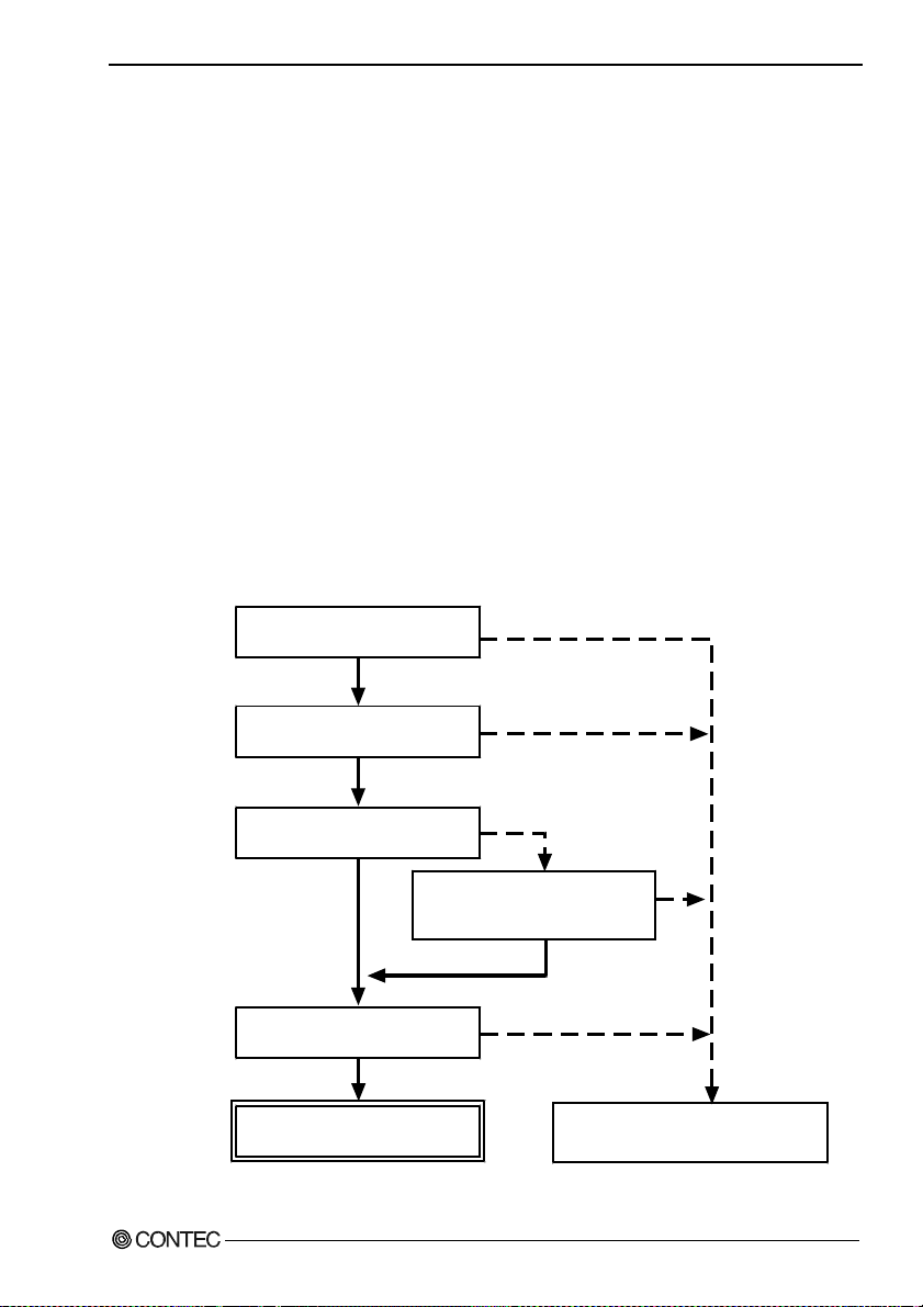
Start
set i8255 function
input/output data
Figure 4.1. I/O setup
DIO-96D-LPE
end
43
Page 51

4. Function
Each bit of control word is as follows.
[1]
[0]
Port A I/O set
Output 0
Input 1
Port C high 4 bits I/O set
Output 0
Input 1
[0]
Port B I/O set
Output 0
Input 1
Port C low 4 bits I/O set
CW7 CW6 CW5 CW4 CW3 CW2 CW1 CW0
Figure 4.2. I/O setup control word
Output 0
Input 1
Table 4.1. Setup value of the control word
Port C
Port B
Port C
(Low 4bit)
Control Ward
D7 D6 D5 D4 D3 D2 D1 D0 hexadecimal Port A
1 0 0 0 0 0 0 0 80 OUTPUT OUTPUT OUTPUT OUTPUT
1 0 0 0 0 0 0 1 81 OUTPUT OUTPUT OUTPUT INPUT
1 0 0 0 0 0 1 0 82 OUTPUT OUTPUT INPUT OUTPUT
1 0 0 0 0 0 1 1 83 OUTPUT OUTPUT INPUT INPUT
1 0 0 0 1 0 0 0 88 OUTPUT INPUT OUTPUT OUTPUT
1 0 0 0 1 0 0 1 89 OUTPUT INPUT OUTPUT INPUT
1 0 0 0 1 0 1 0 8A OUTPUT INPUT INPUT OUTPUT
1 0 0 0 1 0 1 1 8B OUTPUT INPUT INPUT INPUT
1 0 0 1 0 0 0 0 90 INPUT OUTPUT OUTPUT OUTPUT
1 0 0 1 0 0 0 1 91 INPUT OUTPUT OUTPUT INPUT
1 0 0 1 0 0 1 0 92 INPUT OUTPUT INPUT OUTPUT
1 0 0 1 0 0 1 1 93 INPUT OUTPUT INPUT INPUT
1 0 0 1 1 0 0 0 98 INPUT INPUT OUTPUT OUTPUT
1 0 0 1 1 0 0 1 99 INPUT INPUT OUTPUT INPUT
1 0 0 1 1 0 1 0 9A INPUT INPUT INPUT OUTPUT
1 0 0 1 1 0 1 1 9B INPUT INPUT INPUT INPUT
(High 4bit)
DIO-96D-LPE
44
Page 52

4. Function
Data I/O
I/O signals are LVTTL-levels and positive logic.
Input
When input data is low level, [0] is input to the correspondin g bit.
When input data is high level, [1] is input to the corresponding bit.
Output
When [0] is output to the corresponding bit, low level is output to the external part.
When [1] is output to the corresponding bit, high level is output to the external part.
DIO-96D-LPE
45
Page 53

4. Function
Digital Filter Function
Using this feature, the < DIO-96D-L PE > can apply a di gital filter to ever y input pin, t hereby pr eventing
wrong recognition of input signals from carrying noise or a chattering.
Digital Filter Function Principle
The digital filter checks the input signal level during
the sampling time of the c lo ck si gnal . Wh en the
Input Signal
Digital
Filter
Filter Setting Time
Input to PC
signal level remains the same for the digital filter set
time, the digital filter recognizes that signal as the
input signal and changes the signal level of the PC.
If the signal level changes at a frequency shorter than
the set time, therefore, the level change is ignored.
Input Signal
Input to PC
Invalid
Val id
Figure 4.3. Digital Filter Function Principle
Set Digital Filter Time
Set the digital filter time to 0 - 20 (14h).
Setting the digital filter time to 0 disables digital filtering. It is set to 0 when the power is turned on.
Figure 4.4 shows the relationships between digital filter time settings and the actual digital filter times.
Digital Filter Time[sec.] = 2
n: = setting data(0 - 20)
Setting Data
(n)
0 (00h) The filter function is
1 (01h) 0. 2 5μsec 8 (08h) 32μsec 15 (0Fh) 4.096msec
2 (02h) 0.5μsec 9 (09h) 64μsec 16 (10h) 8.192msec
3 (03h) 1μsec 10 (0Ah) 128μsec 17 (11h) 16.384msec
4 (04h) 2μsec 11 (0Bh) 256μsec 18 (12h) 32.768msec
5 (05h) 4μsec 12 (0Ch) 512μsec 19 (13h) 65.536msec
6 (06h) 8μsec 13 (0Dh) 1.024msec 20 (14h) 131.072msec
Digital Filter
Time
not used.
Figure 4.4. Digital Filter Time and Setting Data
CAUTION
- If you set the digital filter time, the filter applies to all input pins. You cannot apply the filter only to
a specific filter.
- Do not set Setting Data to a value outside the above range as doing so can cause the board to
malfunction.
n
/ (8 x 10⁶)
Setting Data
7 (07h) 16μsec 14 (0Eh) 2.048msec
Digital Filter Time Setting Data
(n)
Digital Filter Time
(n)
DIO-96D-LPE
46
Page 54

4. Function
Interrupt Control Function
The < DIO-96D-LPE > can use all of the input signals as interrupt request signals.
The board can generate an interrupt request signal to the PC when the input signal change fr om High to
Low or from Low to High.
When the digital filter (described above) is used, interrupt requests are generated by input signals that
have passed through the filter.
Disabling/enabling Interrupts
Interrupt mask bits can be used to disable or enable the individual bits for interruptions.
Once a certain bit has been interrupt-disabled, no interrupt occurs even when the correspondi ng inp ut
signal changes its level.
To let interrupts occur, enable the corresponding interrupt mask bit for interruptions.
CAUTION
All of the interrupt mask bits are interrupt-disabled when the power is turned on.
Selecting the edge of input signals, at which to generate an interrupt
The input signal edge selection bit can be used to set the input logic for interruption bit by bit.
If you set an input signal edge selection bit to 0, an interrupt occurs when the input value to the
corresponding bit changes from 0 to 1 (at the fall of the input signal fro m High to Lo w).
If you set an input signal edge selection bit to 1, an interrupt occurs when the input value to the
corresponding bit changes from 1 to 0 (at the rise of the input sign al from Low to High).
CAUTION
When the power is turned on, al l of th e i nput signal edge selection bit are set to 0.
Clearing the Interrupt Status and Interr upt Sig nal
Interrupt status bits are used to identify the input signal bit being used for requesting an interrupt.
When an interrupt status is input, the interrupt request signal and the interrupt status are cleared
automatically.
CAUTION
- All of the interrupt status bits are set to 0 when the power is turned on.
- If an interrupt mask bit has been set to disable i nterrupts, the i nterrupt status bit i s not set even whe n
the input signal changes its level.
DIO-96D-LPE
47
Page 55

4. Function
DIO-96D-LPE
48
Page 56

5. About Software
5. About Software
CD-ROM Directory Structure
\
|– Autorun.exe Installer Main Window
| Readmej.html Version information on each API-TOOL (Japanese)
| Readmeu.html Version information on each API-TOOL (English)
.
.
|–––APIPAC Each installer
| |––AIO
| | |––DISK1
| | |––DISK2
| | |––……
| | |––DISKN
| |––AioWdm
| |––CNT
| |––DIO
| |––……
.
.
| ––HELP HELP file
| |––Aio
| |––Cnt
| |––……
.
.
| ––INF Each INF file for OS
| |––WDM
| |––Win2000
| |––Win95
.
.
|––linux Linux driver file
| |––cnt
| |––dio
| |––……
.
.
| ––Readme Readme file for each driver
.
.
| ––Release Driver file on each API-TOOL
| |––API_NT (For creation of a user-specific install program)
| |––API_W95
.
.
| ––UsersGuide Hardwar e Us e r's Gu id e( PD F fil es )
DIO-96D-LPE
49
Page 57

5. About Software
About Software for Windows
The bundled CD-ROM “Driver Library API-PAC(W32)” contains the function s th at provid e th e
following features:
- Digital input/output of specified ports
- Hardware digital input/output of specified bits
- Hardware digital filtering that prevents wrong recognition of input signals from being affected by
noise or chattering.
For details, refer to the he lp file. The help file p rov ides various items of information such as “Fu n c t ion
Reference”, “Sample Programs”, and “FAQs”. Use them for program development and troubleshooti ng.
Accessing the Help File
(1) Click on the [Start] button on the Windows taskbar.
(2) Using the API-DIO(WDM), from the Start Menu, select “Programs” – “CONTEC API-PAC(W32)”
- “DIOWDM” - “API-DIO(WDM) HELP” to display help information.
(3) Using the API-DIO(98/PC), from the Start Menu, select “Programs” – “CONTEC API-PAC(W32) ”
- “Dio” - “API-DIO HELP” to display help information.
Using Sample Programs
Sample programs have been prepared for specific basic applications.
For the API-DIO(WDM), The sample programs are stored in
\Program Files\CONTEC\API-PAC(W32)\DIOWDM\Sample.
For the API-DIO(98/PC), The sample programs are stored in
\Program Files\CONTEC\API-PAC(W32)\Dio\Samples.
To use each sample program, enter its driver number and group num ber set by API-TOOL Configuration
in the DrvNo and GrpNo fields.
Use these sample programs as references for program development and operation check.
Running a Sample Program
(1) Click on the [Start] button on the Windows taskbar.
(2) For the API-DIO(WDM), from the Start Menu, select “Programs” – “CONTEC API-PAC(W32)” –
“DIOWDM” – “SAMPLE…”.
(3) For the API-DIO(98/PC), from the Start Menu, select “Programs” – “CONTEC API-PAC(W32)” –
“Dio” – “SAMPLE…”.
(4) A sample program is invoked.
DIO-96D-LPE
50
Page 58

5. About Software
Sample Programs – Examples
API-DIO(WDM) sample program
- Simple I/O sample program : Input digital data through a specified port.
- Multi ports/bits I/O sample program : Input digital data through a specified multi ports/bits.
- Trigger monitoring sample program : Monitoring rising/falling trigger through a specified
board.
- Interrupt sample program : Services interrupts of a specified board.
API-DIO(98/PC) sample program
-Sample program 1 : Inputs digital data th rough a sp ecified po rt.
-Sample program 2 : Outputs digital data through a specified port.
-Sample program 3 : Inputs/outputs digital data from/to a programmable bo ard.
-Sample program 4 : Inpu ts digital d ata from a specified po rt in th e backg round.
-Sample program 5 : Inputs/outputs digital data from/to a specified bit.
-Sample program 6 : Services interrupts of a specified board.
-Sample program 7 : Provides process control of a sp ecified boa rd.
-Sample program 8 : Performs trigger monitoring of a specified board.
-Sample program 9 : Inputs/outputs digital data through a specified port using BCD data.
-Sample program 10 : Executes inputs/outputs digital (simple functions) at specified bits
-Sample program 11 : Services interrupts of a specified board (using an extended function).
-Sample program (Console) : Inputs/outputs digital data through a specified port.
through a specified port.
DIO-96D-LPE
51
Page 59

5. About Software
Uninstalling the Driver Libraries
The method used to uninstall API-PAC(W32) differs depending on which OS you are using.
Follow the procedure given below.
Uninstall procedure for Windows Vista
< Uninstalling the device driver >
1. Run Device Manager. From [My Computer] - [Control Panel], select [System] and then select the
[Device Manager] tab.
(You can also open Device Manager by right clicking on My Computer and selecting Properties.)
2. All of the hardware that uses the API-TOOL(WDM) driver is registered under the CONTEC
Devices tree.
Open the device tree, select the hardware to uninstall, and then right-click the hardware.
From the popup menu, select [Uninstall].
3. A dialog box opens asking you to confirm whether to uninstall. Select the [Delete the driver
software for this device] checkbox, and then click [OK].
DIO-96D-LPE
52
Page 60

5. About Software
< Uninstall the develop men t envi ro n ment >
Use [My Computer] - [Control Panel] - [Programs and Features] to uninstall the development
environment.
In case of API-***(WDM), select [CONTEC API-***(WDM) VerX.XX (development environment)]
and then click [Uninstall].
In case of API-*** (98/PC), select [CONTEC API-*** (98/PC) xx Ver X.XX] an d t hen cl ick [U ni ns tall].
* "***" contains the driver category name (AIO, CNT, DIO, SMC, etc.).
Uninstall procedure for Windows XP and Windows 2003 Server
< Uninstall the device driver >
Use [My Computer] - [Control Panel] - [Add and Remove Programs] to uninstall the device driver.
In case of API-***(WDM), select [Windows driver package - CONTEC (****)] and then click
[Change/Remove].
In case of API-*** (98/PC), select [CONTEC API-*** (98/PC)xx VerX.XX (development
environment)] and then click [Change/Remove].
* "***" contains the driver category name (caio, ccnt, cdio, csmc, etc.).
DIO-96D-LPE
53
Page 61

5. About Software
< Uninstall the develop men t envi ro n ment >
Use [My Computer] - [Control Panel] - [Add and Remove Programs] to uninstall the development
environment.
In case of API-***(WDM), select [CONTEC API-***(WDM) VerX.XX (development environment)]
and then click [Change/Remove].
In case of API-*** (98/PC), select [CONTEC API-*** (98/PC)xx VerX.XX (development
environment)] and then click [Change/Remove].
* "***" contains the driver category name (AIO, CNT, DIO, SMC, etc.).
DIO-96D-LPE
54
Page 62

5. About Software
About Software for Linux
The Linux version of digital I/O function driver, API-DIO(LNX), provides functions that execute the
following features:
- Digital input/output of specified ports
- Digital input/output of specified bits
- Hardware digital filtering that prevents wrong recognition of input signals from being affected by
noise or chattering.
For details, refer to the he lp file. The help file p rov ides various items of information such as “Fu n c t ion
Reference”, “Sample Programs”, and “FAQs”. Use them for program development and troubleshooti ng.
Driver Software Install Procedure
The Linux version for digital I/O driver, API-DIO(LNX), is supplied as a compressed file
/linux/dio/cdioXXX.tgz on the bundled API-PAC(W32)CD-ROM. (Note: XXX represents the driver
version.)
Mount the CD-ROM as shown below, copy the file to an arbitrary directory, and decompress the file to
install the driver.
For details on using the dr ive r, ref e r to re ad me.tx t and th e help fil e in HT ML fo r mat ex tra ct ed b y
installation.
To install the driv er , log in as a sup eru s er.
Decompression and setup procedure
# cd
# mount /dev/cdrom /mnt/cdrom Mount the CD-ROM.
# cp /mnt/cdrom/linux/dio/cdioXXX.tgz ./ Copy the compressed file.
# tar xvfz cdioXXX.tgz Decompress the compressed file.
................
# cd contec/cdio
# make
Compile the file.
................
# make install Install.
................
# cd config
# ./config Set up the board to be used.
..... Set as follows.........
# ./contec_dio_start.sh Start the driver.
# cd
DIO-96D-LPE
55
Page 63

5. About Software
Accessing the Help File
(1) Invoke a web browser in your X-Window environment.
(2) In the browser, open diohelp.htm in the the contec/cdio/help directory.
Using Sample Programs
Sample programs have been prepared for specific basic applications.
Sample programs for each language are contained in the contec/cdio/samples directory. For compiling
them, refer to the manual for the desired language.
Uninstalling the driver
To uninstall the driver, use the uninstall shell script contained in the contec/cdio directory. For details,
check the contents of th e sc ri pt.
DIO-96D-LPE
56
Page 64

6. About Hardware
6. About Hardware
This chapter provides hardware specifications and hardware-related supplementary information.
For detailed technical information
For further detailed technical information (“Technical Reference” including the information such as an
I/O map, configuration register, etc.), visit the Contec's web site (http://www.contec.com/support/) to
call for it.
Hardware specification
Table 6.1. Specification
Item Specification
I/O
I/O format Unisolated LVTTL-level I/O (Positive logic)
Number of I/O channels 96 channels (all available for interrupts)
Interrupt 96 interrupt input signals are arranged into a single output of interrupt signal INT.
Response time 200nsec within
Rated output current I
Common
I/O address Any 32-byte boundary (Common to I/O part)
Power consumption (Max.) 3.3VDC 300mA
Operating condition 0 - 50°C, 10 - 90%RH (No condensation)
Allowable distance of
signal extension
Bus specification PCI Express Base Specification Rev. 1.0a x1
Dimension (mm)
Connector
Weight
*1 Data “0” and “1” correspond to the High and Low levels, respectively.
Board Dimensions
121.69(L)
An interrupt is generated at the falling edge (HIGH-to-LOW transition) or
rising edge (LOW-to-HIGH transition).
=8mA(Max.) IOH=-8mA(Max.)
OL
Approx. 1.5m (depending on wiring environment)
121.69(L) x 67.90(H)
68 pin 0.8mm pitch connector
HDRA-E68W1LFDT+ [mfd. by HONDA TSUSHIN KOGYO CO., LTD.] or equivalent
to it
60g
DIO-96D-LPE
The standard outside dimension (L) is
the distance from the end of the board to
the outer surface of the slot cover.
67.90(H)
[mm]
57
Page 65

6. About Hardware
Block Diagram
Control
circuit
PCI Express bus
Interrupt
control
DIO-96D-LPE
Figure 6.1. Block Diagram
LVT TL
transceiver
LVT T L
transceiver
LVT TL
transceiver
LVT T L
transceiver
LVT TL
transceiver
LVT T L
transceiver
LVT TL
transceiver
LVT T L
transceiver
LVT TL
transceiver
LVT T L
transceiver
LVT TL
transceiver
LVT T L
transceiver
LVT TL
transceiver
LVT T L
transceiver
LVT TL
transceiver
LVT T L
transceiver
1-A port
(8 points)
1-B port
(8 points)
1-C port (High)
(4 points)
1-C port (Low)
(4 points)
2-A port
(8 points)
2-B port
(8 points)
2-C port (High)
(4 points)
2-C port (Low)
(4 points)
3-A port
(8 points)
3-B port
(8 points)
3-C port (High)
(4 points)
3-C port (Low)
(4 points)
4-A port
(8 points)
4-B port
(8 points)
4-C port (High)
(4 points)
4-C port (Low)
(4 points)
DIO-96D-LPE
58
Page 66

6. About Hardware
Difference from DIO-96D2-LPCI
DIO-96D-LPE
The functions same with conve ntional produc t of DIO-96D2-LP CI are provided w ith the DIO-96D- LPE.
In addition, as there is compatibility in terms of connector shape and pin assignments, it is easy to
migrate from the existing system. So you can use the same operating procedures as DIO-96D2-LPCI.
There are some differences in specifications as shown below.
DIO-96D2-LPCI DIO-96D-LPE
I/O Unisolated TTL-level I/O (Positive logic) Unisolated LVTTL-level I/O (Positive logic)
Rated output current IOL=24mA(Max.) IOH=-15mA(Max.) IOL=8mA(Max.) IOH=-8mA(Max.)
Power consumption 5VDC 950mA(Max.) 3.3VDC 300mA(Max.)
Bus specification
Dimension (mm) 121.69(L) x 63.41(H) 121.69(L) x 67.90(H)
32-bit, 33MHz, Universal key shapes supported
(The 5V pin on the bus must supply 5V.)
PCI Express Base Specification Rev. 1.0a x1
DIO-96D-LPE
59
Page 67

DIO-96D-LPE
User’s Guide
CONTEC CO., LTD. November 2012 Edition
3-9-31, Himesato, Nishiyodogawa-ku, Osaka 555-0025, Japan
Japanese http://www.contec.co.jp/
English http://www.contec.com/
Chinese http://www.contec.com.cn/
No part of this document may be copied or reproduced in any form by any means without prior written
consent of CONTEC CO., LTD. [08162012]
[03102008] Management No. A-51-557
[11062012_rev4] Parts No. LYJB654
 Loading...