

Page 1

PC-HELPER
High Speed Bi-directional
Digital I/O Board for PCI Express
DIO-32DM-PE
User’s Guide
CONTEC CO.,LTD.
Page 2
Check Your Package
Thank you for purchasing the CONTEC product.
The product consists of the items listed below.
Check, with the following list, that your package is complete. If you discover damaged or missing
items, contact your retailer.
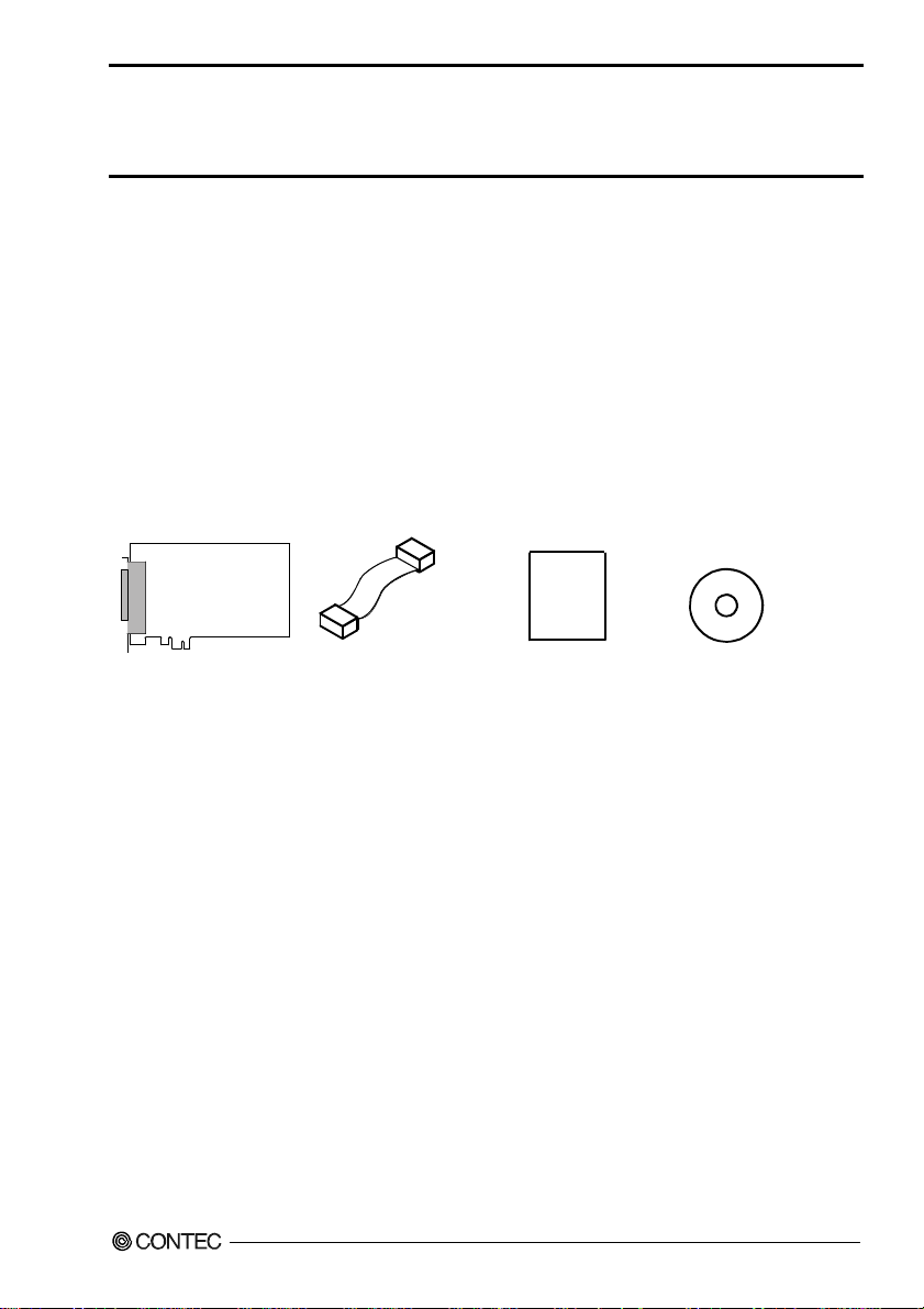
Product Configuration List
- Board [DIO-32DM-PE] …1
- SC Cable(10cm) …1
- First step guide …1
- CD-ROM *1 [API-PAC(W32)] …1
*1 The CD-ROM contains the driver software and User’s Guide (this guide)
Board SC Cable(10cm) First step guide CD-ROM *1
[API-PAC(W32)]
DIO-32DM-PE
i
Page 3

Copyright
Copyright 2013 CONTEC CO., LTD. ALL RIGHTS RESERVED
No part of this document may be copied or reproduced in any form by any means without prior written
consent of CONTEC CO., LTD.
CONTEC CO., LTD. makes no commitment to update or keep current the information contained in this
document. The information in this document is subject to change without notice.
All relevant issues have been considered in the preparation of this document. Should you notice an
omission or any questionable item in this document, please feel free to notify CONTEC CO., LTD.
Regardless of the foregoing statement, CONTEC assumes no responsibility for any errors that may
appear in this document or for results obtained by the user as a result of using this product.
Trademarks
MS, Microsoft, Windows and Windows NT are trademarks of Microsoft Corporation. Other brand and
product names are trademarks of their respective holder.
DIO-32DM-PE
ii
Page 4

Table of Contents
Check Your P ackage................................................................................................................................ i
Copyright .................................................................................................................................................ii
Trademarks ..............................................................................................................................................ii
Table of Contents ...................................................................................................................................iii
1. BEFORE USING THE PRODUCT 1
About the Bo ard ......................................................................................................................................1
Features............................................................................................................................................. 1
Support Software.............................................................................................................................. 2
Cable & Connector (Opt ion) ........................................................................................................3
Accessories (Option).....................................................................................................................3
Customer Su pport.................................................................................................................................... 4
Web Site ...........................................................................................................................................4
Limited Th ree-Years Warranty............................................................................................................... 4
How to Obta in Service............................................................................................................................ 4
Liability ...................................................................................................................................................4
Safety Precautions................................................................................................................................... 5
Safety Information ...........................................................................................................................5
Handling Precautions....................................................................................................................... 6
Environment..................................................................................................................................... 7
Inspection ......................................................................................................................................... 7
Storage.............................................................................................................................................. 7
Disposal ............................................................................................................................................7
2. SETUP 9
What is Setup?......................................................................................................................................... 9
Using the Board under Wi ndows Using the Driver Library API-PAC(W32)............................... 9
Using the Board under Windows Using Software Other than the Driver Library
API-PAC(W32)................................................................................................................................9
Using the Board under an OS Other than Windows..................................................................... 10
Step 1 Installing the Software...............................................................................................................11
About the d river to be used............................................................................................................ 11
Starting th e Install Pr o gram...........................................................................................................12
Select API-DIO(WDM) .................................................................................................................13
Select API-DIO(98/PC) .................................................................................................................14
Step 2 Sett ing the Hardw are .................................................................................................................16
Parts of the Board and Fa ctory Defaults ....................................................................................... 16
Setting the Board ID ......................................................................................................................17
Plugging the Board......................................................................................................................... 18
DIO-32DM-PE
iii
Page 5

Step 3 Installing the Hardware..............................................................................................................19
Turning on the PC ..........................................................................................................................19
When Using API-DIO(WD M ) .......................................................................................................19
When Using API-AIO(98 / PC).......................................................................................................22
Step 4 Initi alizing the Software.............................................................................................................25
When Using API-DIO(WD M ) .......................................................................................................25
When Using API-DIO(98 / PC).......................................................................................................27
Updating the Settings .....................................................................................................................27
Step 5 Oper a tion Checks .......................................................................................................................28
Check Metho d.................................................................................................................................28
When Using API-DIO(WD M ) .......................................................................................................28
When Using API-DIO(98 / PC).......................................................................................................31
Setup Troubleshooting...........................................................................................................................33
Symptoms and Actions...................................................................................................................33
If your problem cannot be resolved ...............................................................................................33
3. EXTERNAL CONNECTION 35
How to conn e ct the connectors .............................................................................................................35
Connector shape .............................................................................................................................35
Connector Pin Assignment.............................................................................................................36
Relationships between API-PAC(W32 ) Logical Ports/Bits and Connector Signal Pins.............3 7
Connection method to the external device -Data I/O-..........................................................................39
Connecting the data I/O signal(DIOA0* - DIOD0*)....................................................................39
Detailed Data I/O Signal Circuit....................................................................................................39
Connection method to the external device -Control I/O-.....................................................................40
Connection to the control signal (EXT**) ....................................................................................40
Detailed C o ntrol Input Signal Circ uit ............................................................................................40
Detailed C o ntrol Outpu t Signal Cir cuit.........................................................................................41
What is the Control Signal? ...........................................................................................................41
Synchroniz ation Contr ol Connecto r s ....................................................................................................43
SC Connecto r s ................................................................................................................................43
Connecting the SC Connectors ( CN2,CN3)..................................................................................44
4. FUNCTION 45
Function Outline ....................................................................................................................................45
Overview.........................................................................................................................................45
Sampling f u nction / gen erating fun c t i on .......................................................................................45
Bus Master T r a nsfer .......................................................................................................................45
Interrupt ( at the time o f bus master transfer).................................................................................46
Status, count....................................................................................................................................46
Sampling function..................................................................................................................................47
Sampling control.............................................................................................................................47
DIO-32DM-PE
iv
Page 6

Generating function...............................................................................................................................48
Generating control.......................................................................................................................... 48
General-purpose I/O fu nction ...............................................................................................................49
Data input .......................................................................................................................................49
Data output .....................................................................................................................................49
Monitoring the output data ............................................................................................................49
Interrupt Control Func tion.................................................................................................................... 50
Disabling/enabling In terrupts ........................................................................................................50
Clearing th e Interrupt S t atus and Int errupt Signal........................................................................50
5. ABOUT SOFTWARE 51
CD-ROM Directory Stru c ture ..............................................................................................................51
About Soft w are for Windows............................................................................................................... 52
Accessing the Help File .................................................................................................................52
Using Sampl e Programs.................................................................................................................53
Uninstalling the Driver Libraries ..................................................................................................55
About Soft w are for Linux .....................................................................................................................58
Driver Software Instal l Procedure .................................................................................................58
Accessing the Help File .................................................................................................................59
Using Sampl e Programs.................................................................................................................59
Uninstalling the driver ...................................................................................................................59
6. ABOUT HARDWARE 61
Hardware sp e cification ......................................................................................................................... 61
Block Diagr am ......................................................................................................................................63
Difference s between DI O - 32DM-PE and PIO-32DM(P CI)................................................................ 64
DIO-32DM-PE
v
Page 7

DIO-32DM-PE
vi
Page 8

1. Before Using the Product
1. Before Using the Product
This chapter provides information you should know before using the product.
About the Board
This product is a PCI Express bus-compliant interface board that supports transfer by bus mastering and
performs input/output between the external device and digital signal. This product features unisolated
LVTTL level (Operating voltage : 3.3V) I/O 32channels and you can select input / output in 16 un its.
Bus master transfer makes it possible to sample quickly large data with transfer rate at 20MHz
maximum. It can be used as a pattern generator that outputs arbitrary digital patterns at high speed.
It can also be used as a general-purpose I/O board when bus mastering is not used.
Windows/Linux driver is bundled with this product.
Using the dedicated library VI-DAQ makes it possible to create each application for LabVIEW.
Features
- 32channels of unisolated LVTTL level I/O (32 input channels / each 16channels for I/O / 32 output
channels are selected.)
This product has the 32channels (operating voltage 3.3VDC, positive logic) of unisolated LV TTL leve l
I/O whose response speed is 50nsec. They can be used for 32bit input, 16bit input plus 16bit output, or
for 32bit output.
Other than I/O bit, this product has the control signal (clock, start, stop and handshake signal (REQ,
ACK) that can control starting and stopping the sampling (input) / generating (output)).
- Sampling and generating with transfer rate at 20MHz maximum
Bus master transfer makes it possible to sample (input) or generate (output) large data with transfer rate
at 20MHz maximum. As the sampling and generating features have their own bus mastering blocks
each made up of two independent channels, the board can generate 16 signals while sampling 16
signals.
- A synchronization control connector is provided for synchronized control of multiple boards.
A synchronization control connector is provided for synchronized control of up to 16 boards. It is also
easy to synchronize operation with other CONTEC boards that have a synchronization control
connector.
- You can use Max. 4 input signals as interrupt request signals at the time of using the general-purpose
I/O.
You can use Max. 4 input signals as interrupt request signals and also disable or enable the interrupt in
bit units at the time of using the general-purpose I/O.
- Windows/Linux compatible driver libraries are attached.
Using the attached driver library API-PAC(W32) makes it possible to create applications of
Windows/Linux. In addition, a diagnostic program by which the operations of hardware can be
checked is provided.
DIO-32DM-PE
1
Page 9

1. Before Using the Product
- Functions and connectors are compatible with PCI compatible board PIO-32DM(PCI).
The functions same with PCI compatible board PIO-32DM(PCI) are provided. In addition, as there is
compatibility in terms of connector shape and pin assignments, it is easy to migrate from the existing
system.
- LabVIEW is supported by a plug-in of dedicated library VI-DAQ.
Using the dedicated library VI-DAQ makes it possible to create each application for LabVIEW.
Support Software
You should use CONTEC support software according to your purpose and development environment.
Windows version of digital I/O driver
A PI-DIO(WDM) / API-DIO(98/PC)
[Stored on the bundled CD-ROM driver library API-PAC(W32)]
The API-DIO(WDM) is the Windows version driver library software that provides products in the form of Win32 API
functions (DLL). Various sample programs such as Visual Basic and Visual C++, etc and diagnostic program *1
useful for checking operation is provided.
< Operating environment >
OS Windows 7, Vista, XP, Server 2003
Adaptation language Visual Basic, Visual C++, Visual C#, Delphi, C++ Builder
For more details on the supported OS, applicable language and how to download the updated version, please visit the
CONTEC’s Web site (http://www.contec.com/apipac/).
*1 : For API-DIO(98/PC), check the device operation by using the sample program.
Linux version of digital I/O driver
API-DIO(LNX)
[Stored on the bundled CD-ROM driver library API-PAC(W32)]
The API-DIO(LNX) is the Linux version driver software which provides device drivers (modules) by shared library
and kernel version. Various sample programs of gcc are provided.
< Operating environment >
OS RedHatLinux, TurboLinux
(For details on supported distributions, refer to Help available after installation.)
Adaptation language gcc
For more details on the supported OS, applicable language and how to download the updated version, please visit the
CONTEC’s Web site (http://www.contec.com/apipac/).
Data acquisition VI library for LabVIEW
(Available for downloading (free of charge) from
VI-DAQ
the CONTEC web site.)
This is a VI library to use in National Instruments LabVIEW.
VI-DAQ is created with a function form similar to that of LabVIEW's Data Acquisition VI, allowing you t o use
various devices without complicated settings.
See http://www.contec.com/vidaq/ for details and download of VI-DAQ.
DIO-32DM-PE
2
Page 10

1. Before Using the Product
Cable & Connector (Option)
Shield Cable with 96-Pin Half-Pitch Connectors at Both Ends : PCB96PS-0.5P (0.5m)
: PCB96PS-1.5P (1.5m)
Flat Cable with 96-Pin Half-Pitch Connectors at Both Ends : PCB96P-1.5 (1.5m)
Shield Cable with 96-Pin D-SUB Connector at One End : PCA96PS-0.5P (0.5m)
: PCA96PS-1.5P (1.5m)
Flat Cable with 96-Pin Half-Pitch Connectors at One End : PCA96P-1.5 (1.5m)
Half Pitch 96P Female Connector Set(5 Pieces) : CN5-H96F
Accessories (Option)
Screw Terminal Unit (M3 x 96P) : EPD-96A *1*2
Screw Terminal Unit (M3.5 x 96P) : EPD-96 *1
Terminal Unit for Cables (M3 x 96P) : DTP-64A *1
*1 PCB96P or PCB96PS optional cable is required separately.
*2 "Spring-up" type terminal is used to prevent terminal screws from falling off.
* Check the CONTEC’s Web site for more information on these options.
DIO-32DM-PE
3
Page 11

1. Before Using the Product
Customer Support
CONTEC provides the following support services for you to use CONTEC products more efficiently
and comfortably.
Web Site
Japanese http://www.contec.co.jp/
English http://www.contec.com/
Chinese http://www.contec.com.cn/
Latest product information
CONTEC provides up-to-date information on products.
CONTEC also provides product manuals and various technical documents in the PDF.
Free download
You can download updated driver software and differential files as well as sample programs available in
several languages.
Note! For product information
Contact your retailer if you have any technical question about a CONTEC product or need its price,
delivery time, or estimate information.
Limited Three-Years Warranty
CONTEC products are warranted by CONTEC CO., LTD. to be free from defects in material and
workmanship for up to three years from the date of purchase by the original purchaser.
Repair will be free of charge only when this device is returned freight prepaid with a copy of the
original invoice and a Return Merchandise Authorization to the distributor or the CONTEC group office,
from which it was purchased.
This warranty is not applicable for scratches or normal wear, but only for the electronic circuitry and
original products. The warranty is not applicable if the device has been tampered with or damaged
through abuse, mistreatment, neglect, or unreasonable use, or if the original invoice is not included, in
which case repairs will be considered beyond the warranty policy.
How to Obtain Service
For replacement or repair, return the device freight prepaid, with a copy of the original invoice. Please
obtain a Return Merchandise Authorization number (RMA) from the CONTEC group office where you
purchased before returning any product.
* No product will be accepted by CONTEC group without the RMA number.
Liability
The obligation of the warrantor is solely to repair or replace the product. In no event will the
warrantor be liable for any incidental or consequential damages due to such defect or consequences that
arise from inexperienced usage, misuse, or malfunction of this device.
DIO-32DM-PE
4
Page 12
1. Before Using the Product
Safety Precautions
Understand the following definitions and precautions to use the product safely.
Safety Information
This document provides safety information using the following symbols to prevent accidents resulting
in injury or death and the destruction of equipment and resources. Understand the meanings of these
labels to operate the equipment safely.
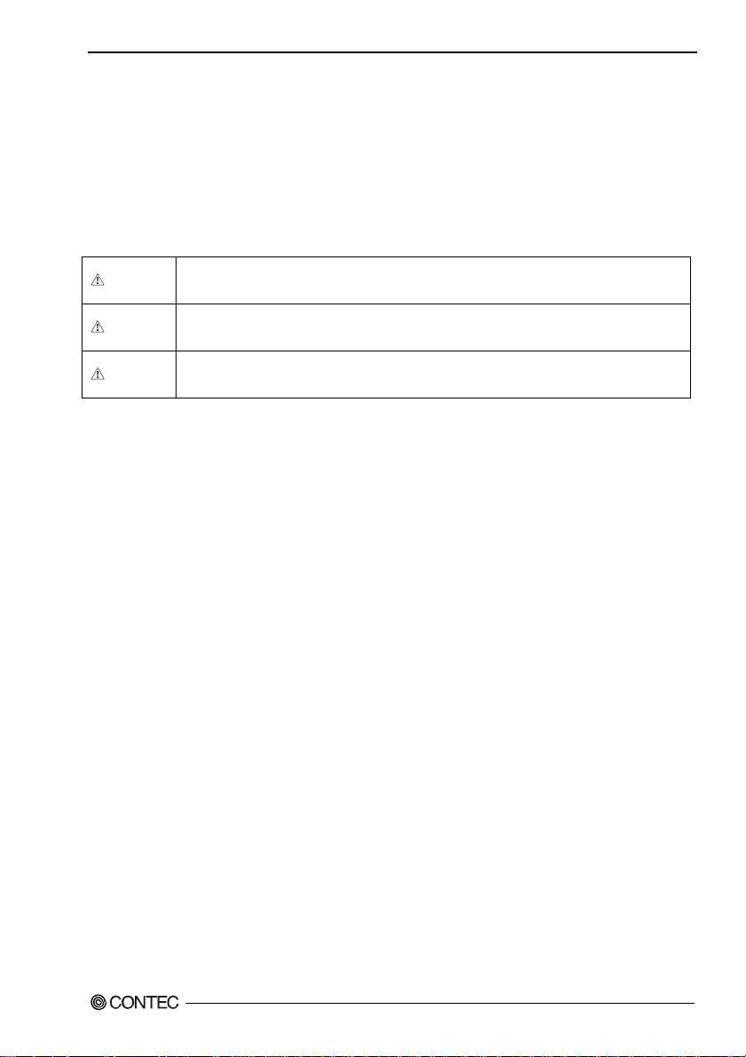
DANGER
WAR NI NG
CAUTION
DANGER indicates an imminently hazardous situation which, if not avoided, will
result in death or serious injury.
WARNING indicates a potentially hazardous situation which, if not avoided, could
result in death or serious injury.
CAUTION indicates a potentially hazardous situation which, if not avoided, may
result in minor or moderate injury or in property damage.
DIO-32DM-PE
5
Page 13
1. Before Using the Product
Handling Precautions
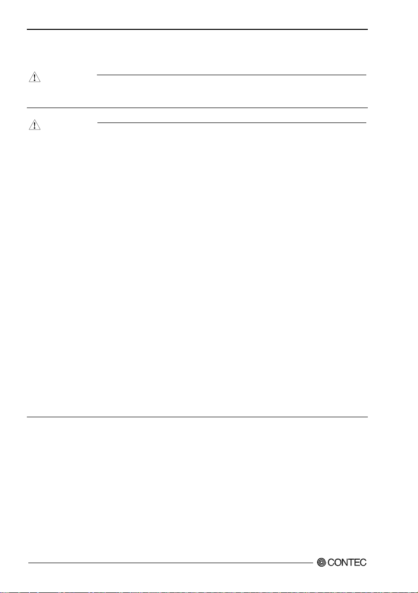
DANGER
Do not use the product where it is exposed to flammable or corrosive gas. Doing so may result in
an explosion, fire, electric shock, or failure.
CAUTION
- There are switches and jumpers on this product that need to be set in advance.
Be sure to check these before installing to the expansion slot.
- Only set the switches and jumpers on this product to the specified settings.
Otherwise, this product may malfunction, overheat, or cause a failure.
- Do not strike or bend this product.
Otherwise, this product may malfunction, overheat, cause a failure or breakage.
- Do not touch this product's metal plated terminals (edge connector) with your hands.
Otherwise, this product may malfunction, overheat, or cause a failure.
If the terminals are touched by someone's hands, clean the terminals with industrial alcohol.
- Do not install or remove this product to or from the expansion slot while the computer's power or
expansion unit is turned on.
Otherwise, this product may malfunction, overheat, or cause a failure.
Be sure that the personal computer power is turned off.
- Make sure that your PC or expansion unit can supply ample power to all the products installed.
Insufficiently energized products could malfunction, overheat, or cause a failure.
- The specifications of this product are subject to change without notice for enhancement and quality
improvement.
Even when using this product continuously, be sure to read the user’s guide and understand the
contents.
- Do not modify this product. CONTEC will bear no responsibility for any problems, etc., resulting
from modifying this product.
- Regardless of the foregoing statements, CONTEC is not liable for any damages whatsoever
(including damages for loss of business profits) arising out of the use or inability to use this
CONTEC product or the information contained herein.
DIO-32DM-PE
6
Page 14

1. Before Using the Product
Environment
Use this product in the following environment. If used in an unauthorized environment, the product
may overheat, malfunction, or cause a failure.
Operating temperature
0 - 50°C
Operating humidity
10 - 90%RH (No condensation)
Corrosive gases
None
Floating dust particles
Not to be excessive
Inspection
Inspect the product periodically as follows to use it safely.
- Check that the bus connector
of the board and its cable have
been plugged correctly.
- Check that the board has
no dust or foreign matter
adhering.
~
~
- The gold-plated leads of the bus
connector.
Storage
When storing this product, keep it in its original packing form.
(1) Put this product in the storage bag.
(2) Wrap it in the packing material, then put it in the box.
(3) Store the package at room temperature at a place free from direct sunlight, moisture, shock,
vibration, magnetism, and static electricity.
Disposal
When disposing of the product, follow the disposal procedures stipulated under the relevant laws and
municipal ordinances.
DIO-32DM-PE
7
Page 15

1. Before Using the Product
DIO-32DM-PE
8
Page 16

2. Setup
2. Setup
This chapter explains how to set up the board.
What is Setup?
Setup means a series of steps to take before the product can be used.
Different steps are required for software and hardware.
The setup procedure varies with the OS and software used.
Using the Board under Windows
Using the Driver Library API-PAC(W32)
This section describes the setup procedure to be performed before you can start developing application
programs for the board using the bundled CD-ROM “Driver Library API-PAC(W32)”.
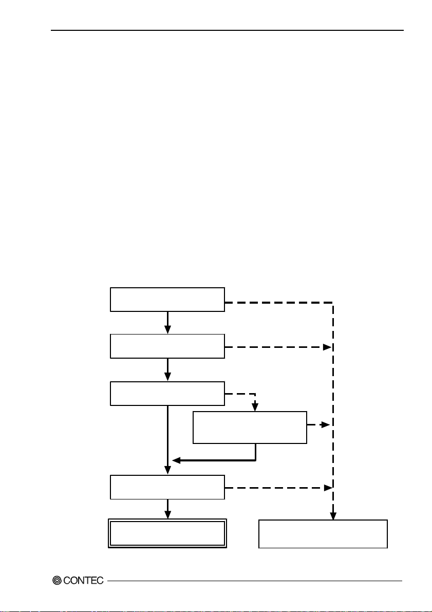
Taking the following steps sets up the software and hardware. You can use the diagnosis program
later to check whether the software and hardware function normally.
Step 1 Installing the Software
Step 2 Setting the Hardware
Step 3 Installing the Hardware
Step 4 Initializing the Software
Step 5 Operation Checks
If Setup fails to be performed normally, see the “Setup Troubleshooting” section at the end of this
chapter.
*1 : For API-DIO(98/PC), check the device operation by using the sample program.
*1
Using the Board under Windows
Using Software Other than the Driver Library API-PAC(W32)
For setting up software other than API-PAC(W32), refer to the user’s guide for that software. See also
the following parts of this user’s guide as required.
This chapter Step 2 Setting the Hardware
This chapter Step 3 Installing the Hardware
Chapter 3 External Connection
Chapter 6 About Hardware
DIO-32DM-PE
9
Page 17

2. Setup
Using the Board under an OS Other than Windows
For using the board under an OS other than Windows, see the following parts of this user’s guide.
This chapter Step 2 Setting the Hardware
Chapter 3 External Connection
Chapter 6 About Hardware
DIO-32DM-PE
10
Page 18
2. Setup
Step 1 Installing the Software
This section describes how to install the Driver libraries.
Before installing the hardware on your PC, install the Driver libraries from the bundled
API-PAC(W32) CD-ROM.
The following description assumes the operating system as Windows XP. Although some user
interfaces are different depending on the OS used, the basic procedure is the same.
About the driver to be used
Two Analog I/O drivers are available : API-DIO(WDM) and API-DIO(98/PC).
API-DIO(WDM) is a new driver to perform analog I/O under Windows.
API-DIO(WDM) was developed to improve the conventional product version of API-DIO(98/PC) in the
ease of use and functionality.
It is advisable to use API-DIO(WDM) for you to use an analog I/O device. API-DIO(WDM) will
support new OS and devices in the future but will not support Windows NT 4.0, Windows 95, ISA bus.
Use API-DIO(98/PC) if your operating environment contains such an unsupported piece of software or
hardware.
Check the following selection guide to easily select the driver to be used.
OS to be used
Windows Vista
Windows XP/Windows 2000
PCI bus, PC Card
Use the digital board for
the fisrt time?
Ye s
Language to be used
VC.Net, VB.Net, VC#.Net
VC6, VB6
API-DIO(WDM)
DIO-32DM-PE
Device type
Windows Me/98/95
Windows NT 4.0
ISA Bus
Already used.
The existing system
upgrade using
API-DIO(98/PC)?
No
VC2, 4, 5, VB4, 5,
Delphi, C++Builder
Ye s
API-DIO(98/PC)
11
Page 19
2. Setup
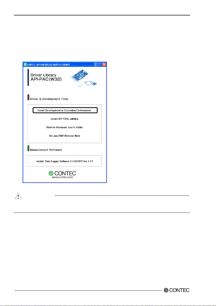
Starting the Install Program
(1)
Load the CD-ROM [API-PAC(W32)] on your PC.
(2)
The API-PAC(W32) Installer window appears automatically.
If the panel does not appear, run (CD-ROM drive letter):\AUTORUN.exe.
(3)
Click on the [Install Development or Execution Environment] button.
* When using the Windows Vista, driver is automatically installed.
CAUTION
Before installing the software in Windows Vista, XP, Server 2003 and 2000, log in as a user with
administrator privileges.
DIO-32DM-PE
12
Page 20
2. Setup
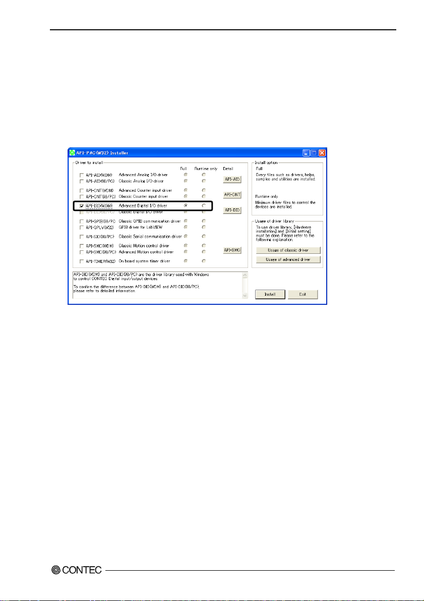
Select API-DIO(WDM)
Selecting API-DIO(WDM)
(1)
The following dialog box appears to select “Driver to install” and “Install option”, “Usage of
driver library”.
(2)
Select the "Advanced Digital I/O driver".
(3)
Click on the [Install] button.
* Clicking the [API-DIO] button under the “Detail” displays detailed information about
API-DIO(WDM) and API-DIO(98/PC).
Run the installation
(1)
Complete the installation by following the instructions on the screen.
(2)
The Readme file appears when the installation is complete.
DIO-32DM-PE
13
Page 21

2. Setup
Select API-DIO(98/PC)
Selecting API-DIO(98/PC)
(1)
The following dialog box appears to select “Driver to install” and “Install option”, “Usage of
driver library”.
(2)
Select “Classic Digital I/O driver”.
(3)
Click on the [Install] button.
* Clicking the [API-DIO] button under the “Detail” displays detailed information about
API-DIO(WDM) and API-DIO(98/PC).
DIO-32DM-PE
14
Page 22
2. Setup
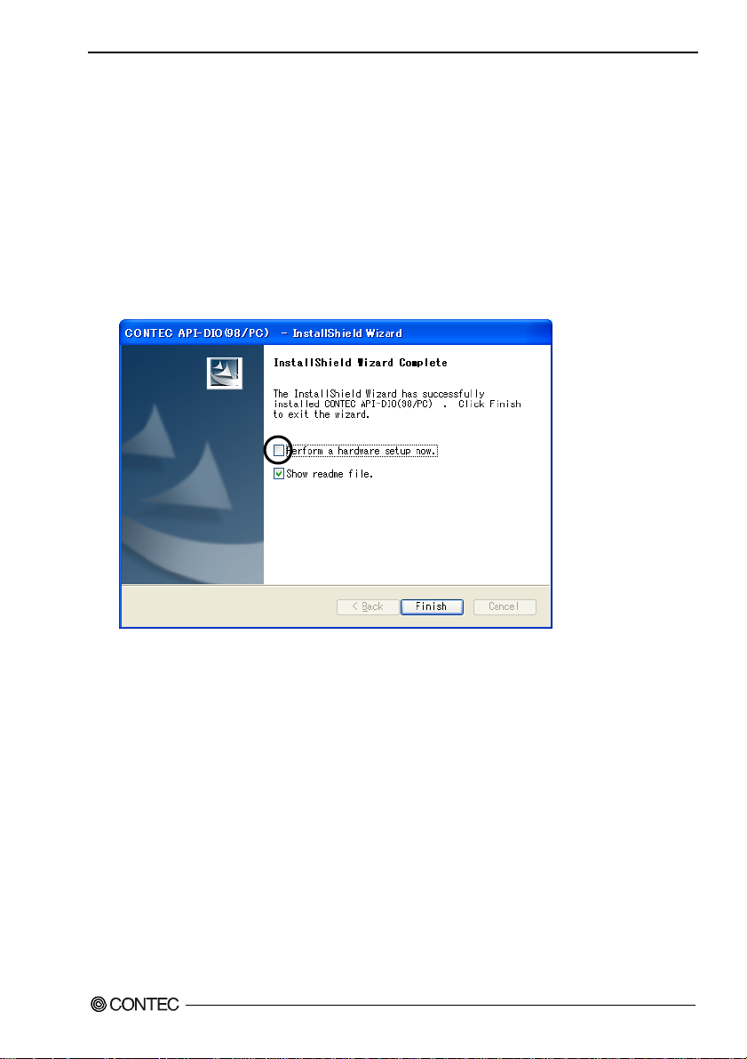
Executing the Installation
(1)
Follow the on-screen instructions to proceed to install.
(2) When the required files have been copied, the “Perform a hardware setup now(API-TOOL
Configuration)” and “Show readme file” check boxes are displayed.
When you are installing the software or hardware for the first time:
1) Uncheck “Perform a hardware setup now”.
2) Click on the [Finish] button.
Go to Step 2 to set and plug the hardware.
* When the hardware has already been installed:
Check “Perform a hardware setup now(API-TOOL Configuration)”, then go to Step 4
“Initializing the Software”.
You have now finished installing the software.
DIO-32DM-PE
15
Page 23

2. Setup
ace connecto
(
)
Step 2 Setting the Hardware
This section describes how to set the board and plug it on your PC.
The board has some switches to be preset.
Check the on-board switches before plugging the board into an expansion slot.
The board can be set up even with the factory defaults untouched. You can change board settings later.
Parts of the Board and Factory Defaults
Figure 2.1. shows the names of major parts on the board.
Note that the switch setting shown below is the factory default.
DIO-32DM-PE
CN2, CN3 SW1
BOARD ID
- Interf
(CN1)
r
Figure 2.1. Component Locations
- SC Connector
CN2, CN3
(CN2) (CN3)
-Board ID setting switch
SW1
BOARD ID
8
9
7
A
6
B
5
4
3
E
2
F
1
0
C
D
DIO-32DM-PE
16
Page 24

2. Setup
Setting the Board ID
If you install two or more boards on one personal computer, assign a different ID value to each of the
boards to distinguish them.
The board IDs can be set from 0 - Fh to identify up to sixteen boards.
If only one board is used, the original factory setting (Board ID = 0) should be used.
Setting Procedure
To set the board ID, use the rotary switch on the board. Turn the SW1 knob to set the board ID as
shown below.
SW1
BOARD ID
8
9
7
A
6
B
5
C
4
D
3
E
2
F
Factory setting:
0
1
Figure 2.2. Board ID Settings (SW1)
(Board ID= 0)
DIO-32DM-PE
17
Page 25

2. Setup
Plugging the Board
(1) Before plugging the board, shut down the system, unplug the power code of your PC.
(2) Remove the cover from the PC so that the board can be mounted.
(3) Plug the board into an expansion slot.
(4) Attach the board bracket to the PC with a screw.
(5) Put the cover back into place.
CAUTION
- Do not touch the board's metal plated terminals (edge connector) with your hands.
Otherwise, the board may malfunction, overheat, or cause a failure.
If the terminals are touched by someone's hands, clean the terminals with industrial alcohol.
- Do not install or remove the board to or from the slot while the computer's power or expansion unit is
turned on.
Otherwise, the board may malfunction, overheat, or cause a failure.
Be sure that the personal computer power is turned off.
- Make sure that your PC or expansion unit can supply ample power to all the boards installed.
Insufficiently energized boards could malfunction, overheat, or cause a failure.
DIO-32DM-PE
18
Page 26

2. Setup
Step 3 Installing the Hardware
For using an expansion board under Windows, you have to let the OS detect the I/O addresses and
interrupt level to be used by the board. The process is referred to as installing the hardware.
In the case of using two or more boards, make sure you install one by one with the Add New Hardware
Wizard.
Turning on the PC
Turn on the power to your PC.
CAUTION
- The board cannot be properly installed unless the resources (I/O addresses and interrupt level) for
the board can be allocated. Before attempting to install the board, first determine what PC
resources are free to use.
- The resources used by each board do not depend on the location of the PCI Express bus slot or the
board itself. If you remove two or more boards that have already been installed and then remount
one of them on the computer, it is unknown that which one of the sets of resources previously
assigned to the two boards is assigned to the remounted board. In this case, you must check the
resource settings.
When Using API-DIO(WDM)
(1) The “Found New Hardware Wizard” will be started.
Select “No, not this time” and then click the “Next” button.
DIO-32DM-PE
19
Page 27

2. Setup
(2) When “Multimedia Controller” is displayed, select “Install from a list or s
location[Advanced]” and then specify that folder on the CD-ROM which contains the setup
information (INF) file to register the board.
When the model name of hardware is displayed, select “Install the software automatically
[Recommended]” and then click on the “Next” button.
Source folder
The setup information (INF) file is contained in the following folder on the bundled CD-ROM.
Windows Vista, XP, Server 2003, 2000 \INF\Wdm\Dio
pecific
API-PAC version may be
different.
\INF\Wdm\Dio
DIO-32DM-PE
20
Page 28

2. Setup
* The name of the board
you have just added is
displayed.
- DIO-32DM-PE
You have now finished installing the hardware.
DIO-32DM-PE
21
Page 29

2. Setup
When Using API-AIO(98/PC)
(1) The “Found New Hardware Wizard” will be started.
If you are using Windows NT 4.0, the “Found New Hardware Wizard” is not started.
Go to Step 4 “Initializing the Software”.
Select “No, not this time” and then click the “Next” button.
(2) Select “Install from a list or s
pecific location[Advanced]” and then click the “Next” button.
DIO-32DM-PE
22
Page 30

2. Setup
(3) Specify that folder on the CD-ROM which contains the setup information (INF) file to register the
board.
* The name of the board
you have just added is
displayed.
- DIO-32DM-PE
Source folder
The setup information (INF) file is contained in the following folder on the bundled CD-ROM.
Windows Vista, XP, Server 2003, 2000 \INF\Win2000\Dio\PCI
Example of specifying the folder for use under Windows XP
DIO-32DM-PE
\INF\Win2000\Dio\PCI
23
Page 31

2. Setup
CAUTION
In Windows XP, the Hardware Wizard displays the following alert dialog box when you have
located the INF file. This dialog box appears, only indicating that the relevant driver has not
passed Windows Logo testing, and it can be ignored without developing any problem with the
operation of the board.
In this case, click on the [Continue Anyway] button.
You have now finished installing the hardware.
* The name of the board
you have just added is
displayed.
- DIO-32DM-PE
DIO-32DM-PE
24
Page 32

2. Setup
Step 4 Initializing the Software
The driver library requires the initial setting to recognize the execution environment. It is called the
initialization of the Driver library.
When Using API-DIO(WDM)
API-DIO(WDM) is initialized automatically during hardware installation. Therefore, if you want to
use it with its initial settings, you can skip the setting procedure described in Step 4. To change the
device name, follow the setting procedure shown below.
Setting the device name
(1) Run Device Manager. From [My Computer] - [Control Panel], select [System] and then select the
[Device Manager] tab.
(You can also open Device Manager by right clicking on My Computer and selecting Properties.)
* The name of the board
you have just added is
displayed.
- DIO-32DM-PE “DIO000”
(2) The installed hardware appears under the CONTEC Devices node. Open the CONTEC Devices
node and select the device you want to setup (the device name should appear highlighted). Click
[Properties].
DIO-32DM-PE
25
Page 33

2. Setup
(3) The property page for the device opens.
Enter the device name in the common settings tab page and then click [OK].
The device name you set here is used later when programming.
* The name of the board
you have just added is
displayed.
- DIO-32DM-PE
* The initial device name that appears is a default value. You can use this default name if you wish.
* Make sure that you do not use the same name for more than one device.
You have now finished installing the initial setting of Software.
DIO-32DM-PE
26
Page 34

2. Setup
Whe n Us ing API-DIO(98/PC)
(1) Open the Start Menu, then select “Programs” – “CONTEC API-PAC(W32)” – “API-TOOL
Configuration”.
(2) Click the [DIO] icon.
API-TOOL Configuration detects boards automatically.
The detected boards are listed.
Updating the Settings
(1) Select “Save setting to registry…” from the “File” menu.
You have now finished installing the initial setting of Software.
DIO-32DM-PE
27
Page 35

2. Setup
Step 5 Operation Checks
You must make sure that the board and driver software operate normally. By taking this step, you can
make sure that the board has been set up correctly.
Check Method
Connect the board to a remote device to test the input/output and check the execution environment.
Set the board in the default factory.
To connect an external device, see Chapter 3 “External Connection”.
When Using API-DIO(WDM)
Use the diagnostic program to check the operation.
Starting the Diagnosis Program
Open the “Properties” page of the device that was used for the software initialization, and press the
[Diagnosis] button.
DIO-32DM-PE
28
Page 36

2. Setup
Checking Digital Inputs and Outputs
The main panel of the Diagnosis Program appears.
You can check the current operation states of the board in the following boxes:
“Input Port” : Displays input values bit by bit at fixed time intervals.
“Output Port” : Mouse operation allows the data to output or display.
“Interrupt” : Displays the number of interrupts detected bit by bit.
* The name of the board
you have just added is
displayed.
- DIO-32DM-PE
* Switch the I/O direction.
To use the function execution time measurement feature, click on the [Measurement Time] button.
Enter the I/O start port and the number of ports, then press the measurement button. The time for each
execution of a function will be measured.
DIO-32DM-PE
29
Page 37

2. Setup
Diagnosis Report
(1) Clicking on the [Show Diagnosis Report] button displays detailed data such as board settings and
the diagnosis results while saving them in text format.
The Diagnosis Program performs “board presence/absence check”, “driver file test”, “board setting
test”, and so on.
CAUTION
Before executing diagnosis report output, unplug the cable from the board.
* The name of the board
you have just added is
displayed.
- DIO-32DM-PE
(2) A diagnosis report is displayed as shown below.
* The name of the board
you have just added is
displayed.
- DIO-32DM-PE
DIO-32DM-PE
30
Page 38

2. Setup
When Using API-DIO(98/PC)
C
heck the device operation by using the sample program.
Running a Sample Program
From the “Start” menu, select [Programs] – [CONTEC API-PAC(W32)] – [Dio] – [PIO-32DM] –
[SAMPLE Output 32bit].
(1) Enter in [GrpNo:] the “Group No.” which you set in “API-TOOL Configuration”, and then press
the [DioOpen] button. Make sure that the [Ret:] field displays the following information.
(2) Press the [Condition...] button to display the “Generating Condition” window, and then press the
[OK] button.
DIO-32DM-PE
31
Page 39

2. Setup
(3) Press the [Data…] button to create output data.
(4) Press the [DataSet] button to set the output data in the buffer for the bus master.
(5) Pressing the [Start] button starts bus master transfer, and once the output is completed, the
following information appears.
DIO-32DM-PE
32
Page 40

2. Setup
Setup Troubleshooting
Symptoms and Actions
No output can be obtained.
Use API-TOOL Configuration to check whether the board name setting is wrong.
The board works with the Diagnosis Program but not with an application.
The Diagnosis Program is coded with API-TOOL functions. As long as the board operates with the
Diagnosis Program, it is to operate with other applications as well. In such cases, review your program
while paying attention to the following points:
- Check the return values of functions.
- Refer to the source code of sample program.
The OS won't normally get started or detect the board.
< For using the
Refer to the “Troubleshooting” in API-DIO(WDM) HELP
< For using the
Turn off the power to your PC, then unplug the board . Restart the OS and delete the board settings of
API-TOOL Configuration. Turn off the PC again, plug the board, and restart the OS. Let the OS
detect the board and use API-TOOL Configuration to register board settings.
API-DIO(WDM) >
API-DIO(98/PC) >
If your problem cannot be resolved
Contact your retailer.
DIO-32DM-PE
33
Page 41

2. Setup
DIO-32DM-PE
34
Page 42

3. External Connection
3. External Connection
This chapter describes the interface connectors on the product and the external I/O circuits.
Check the information available here when connecting an external device.
How to connect the connectors
Connector shape
To connect an external device to this product, plug the cable from the device into the interface
connector (CN1) shown below.
Interface connector (CN1)
B48 A48
B47 A47
B02 A02
B01 A01
* Please refer to chapter 1 for more information on the supported cable and accessories.
Figure 3.1. Interface Connector and Applicable Cable Connector
- Connector used
PCR-E96LMD+
[mfd. by HONDA TSUSHIN
KOGYO CO., LTD.]
or equivalence to it
- Compatible connectors
PCR-E96FA+
[mfd. by HONDA TSUSHIN
KOGYO CO., LTD.]
or equivalence to it
DIO-32DM-PE
35
Page 43

3. External Connection
Connector Pin Assignment
GND
B48 A48
GND
B47 A47
GND
B46 A46
EXTCLK1
B45 A45
GND
EXTSTART1
B44 A44
B43 A43
GND
B42 A42
EXTSTOP1
B41 A41
B48 A48
GND
B40 A40
EXTREQ1
B39 A39
GND
B38 A38
EXTACK1
B37 A37
GND
B36 A36
GND
B35 A35
GND
B34 A34
DIOD07
B33 A33
GND
B32 A32
DIOD06
B31 A31
GND
B30 A30
DIOD05
B29 A29
GND
B28 A28
DIOD04
B27 A27
GND
B26 A26
DIOD03
B25 A25
GND
B24 A24
DIOD02
B23 A23
GND
B22 A22
DIOD01
B21 A21
GND
B20 A20
DIOD00
B19 A19
GND
B18 A18
DIOC07
B17 A17
GND
B16 A16
DIOC06
B15 A15
GND
B14 A14
DIOC05
B13 A13
GND
B12 A12
DIOC04
B11 A11
GND
B10 A10
DIOC03
B09 A09
B01
GND
B08 A08
DIOC02
B07 A07
GND
B06 A06
DIOC01
B05 A05
GND
B04 A04
DIOC00
B03 A03
N.C.
B02 A02
N.C.
B01
[49]
[96]
[1]
[48]
- [ ] shows the pin No. of HONDA TSUSHIN KOGYO CO., LTD. specification.
* Can be used as an interrupt signal when used as general-purpose I/O.
A01
A01
GND
GND
GND
EXTCLK0
GND
EXTSTART0
GND
EXTSTOP0
GND
EXTREQ0
GND
EXTACK0
GND
GND
GND
DIOB07
GND
DIOB06
GND
DIOB05
GND
DIOB04
GND
DIOB03
GND
DIOB02
GND
DIOB01
GND
DIOB00
GND
DIOA07
GND
DIOA06
GND
DIOA05
GND
DIOA04
GND
DIOA03 *
GND
DIOA02 *
GND
DIOA01 *
GND
DIOA00 *
N.C.
N.C.
DIO-32DM-PE
36
Page 44

3. External Connection
I/O signal DIOA00 - DIOA07
DIOA00 - DIOA07
DIOA00 - DIOA07 I/O signal DIOA00 - DIOA07
DIOB00 - DIOB07 I/O signal DIOB00 - DIOB07
DIOC00 - DIOC07 I/O signal DIOC00 - DIOC07
DIOD00 - DIOD07 I/O signal DIOD00 - DIOD07
EXTCLK0 - EXTCLK1 External clock input
EXTSTART0 - EXTSTART1 External start signal
EXTSTOP0 - EXTSTOP1 External stop signal
EXTREQ0 - EXTREQ1 REQ signal
EXTACK0 - EXTACK1 ACK signal
GND This is connected to GND of slot.
N.C. This pin is left unconnected.
DIOA00 - DIOA03 can be used as interrupt signal DIOIn00 - DIOIn03 at
the time of general-purpose I/O..
Figure 3.2. Pin Assignments of Interface Connector
Relationships between API-PAC(W32) Logical Ports/Bits and Connector Signal Pins
The following table lists the relationships between the connector signal pins and the logical port/bit
numbers used for I/O functions when applications are written with API-PAC(W32).
CAUTION
The logical port and logical bit numbers are virtual port and bit numbers that enable programming
independent of board I/O addresses or board types.
For details, refer to API-DIO HELP available after installing API-PAC(W32).
Setup1
Table 3.1. Logical Ports, Logical Bits, and Connector Signal Pins < Setup1 >
D7 D6 D5 D4 D3 D2 D1 D0
Input Logical
Ports0
Input Logical
Ports1
Input Logical
Ports2
Input Logical
Ports3
DIOA07
DIOA06
DIOA05
DIOA04
DIOA03
DIOA02
[7]
[6]
[5]
[4]
[3]
DIOB07
DIOB06
DIOB05
DIOB04
[15]
[14]
[13]
DIOC07
DIOC06
[22]
DIOD06
[30]
DIOC05
[21]
DIOD05
[29]
[23]
DIOD07
[31]
Note : DIOAxx, DIOBxx, DIOCxx and DIODxx represents the CN1 input signal.
[xx] represents the logical bit.
[12]
DIOC04
[20]
DIOD04
[28]
DIOB03
[11]
DIOC03
[19]
DIOD03
[27]
[2]
DIOB02
[10]
DIOC02
[18]
DIOD02
[26]
DIOA01
[1]
DIOB01
[9]
DIOC01
[17]
DIOD01
[25]
DIOA00
[0]
DIOB00
[8]
DIOC00
[16]
DIOD00
[24]
DIO-32DM-PE
37
Page 45

3. External Connection
Setup2
Table 3.2. Logical Ports, Logical Bits, and Connector Signal Pins < Setup2 >
D7 D6 D5 D4 D3 D2 D1 D0
Input Logical
Ports0
Input Logical
Ports1
Output Logical
Ports2
Output Logical
Ports3
DIOA07
DIOA06
DIOA05
DIOA04
DIOA03
DIOA02
DIOA01
[7]
[6]
[5]
[4]
[3]
[2]
DIOB07
DIOB06
DIOB05
DIOB04
DIOB03
[15]
[14]
[13]
[12]
D7 D6 D5 D4 D3 D2 D1 D0
DIOC07
DIOC06
DIOC05
[23]
[22]
DIOD07
DIOD06
[31]
[30]
Note :
DIOAxx and DIOBxx represents the CN1 input signal and DIOCxx and DIODxx
represents the CN1 output signal.
[xx] represents the logical bit.
[21]
DIOD05
[29]
DIOC04
[20]
DIOD04
[28]
[11]
DIOC03
[19]
DIOD03
[27]
DIOB02
[10]
DIOC02
[18]
DIOD02
[26]
[1]
DIOB01
[9]
DIOC01
[17]
DIOD01
[25]
DIOA00
[0]
DIOB00
[8]
DIOC00
[16]
DIOD00
[24]
Setup3
Table 3.3. Logical Ports, Logical Bits, and Connector Signal Pins < Setup3 >
D7 D6 D5 D4 D3 D2 D1 D0
Output Logical
Ports0
Output Logical
Ports1
Output Logical
Ports2
Output Logical
Ports3
DIOA07
DIOA06
DIOA05
DIOA04
DIOA03
DIOA02
[7]
[6]
[5]
[4]
[3]
DIOB07
DIOB06
DIOB05
DIOB04
[15]
[14]
[13]
DIOC07
DIOC06
[22]
DIOD06
[30]
DIOC05
[21]
DIOD05
[29]
[23]
DIOD07
[31]
Note : DIOAxx, DIOBxx, DIOCxx and DIODxx represents the CN1 output signal.
[xx] represents the logical bit.
[12]
DIOC04
[20]
DIOD04
[28]
DIOB03
[11]
DIOC03
[19]
DIOD03
[27]
[2]
DIOB02
[10]
DIOC02
[18]
DIOD02
[26]
DIOA01
[1]
DIOB01
[9]
DIOC01
[17]
DIOD01
[25]
DIOA00
[0]
DIOB00
[8]
DIOC00
[16]
DIOD00
[24]
DIO-32DM-PE
38
Page 46

3. External Connection
Connection method to the external device
-Data I/O-
Connecting the data I/O signal(DIOA0* - DIOD0*)
These lines input from and output to external devices and can be configured in 16bit with the software.
Input and output and setting procedures are the same whether these lines are used for general-purpose
digital I/O or bus master transferring and they can be configured in three different settings as shown
below:
Table 3.4. I/O signal
Signal name Setup1 Setup2 Setup3
DIOA00 - DIOA07 Input Input Output
DIOB00 - DIOB07 Input Input Output
DIOC00 - DIOC07 Input Output Output
DIOD00 - DIOD07 Input Output Output
When settings 1 and 2 are used for general-purpose digital I/O, DIOA00 through DIOA03 can be used
as interrupts (rising edge).
Detailed Data I/O Signal Circuit
SN74LV245A
Ω
22
Figure 3.3. Data I/O Signal Circuit
DIO-32DM-PE
Board
DIO A**
DIO B**
DIO C**
DIO D**
INPUT/OUTPUT
GND GND
External circuit
5V TTL IC or LVTTL IC
39
Page 47

3. External Connection
Connection method to the external device
-Control I/O-
Connection to the control signal (EXT**)
In order to control bus mastering from outside, five signals are provided each for pattern I/O. Before
using the signals to be input as control signals please verify their pulse widths.
"0" at the end of a signal name indicates a pattern input signal and "1" a pattern output signal.
Table 3.5. Control signal
Signal name Direction Usage Signal name Direction Usage
EXTCLK0 In Pattern input clock EXTCLK1 In Pattern output clock
EXTSTART0 In Pattern input start signal EXTSTART1 In Pattern output start signal
EXTSTOP0 In Pattern input stop signal EXTSTOP1 In Pattern output stop signal
EXTREQ0 In Pattern input REQ signal EXTREQ1 Out Pattern output REQ signal
EXTACK0 Out Pattern input ACK signal EXTACK1 In Pattern output ACK signal
Detailed Control Input Signal Circuit
Control signals to be input include clock, start, stop, and handshake input signals.
GND
EXTCLK0/1
EXTSTART0/1
EXTSTOP0/1
EXREQ0
EXTACK1
External circuit
5V TTL IC or LVTTL IC
SN74LV245A
Board
22
Ω
Input pin
Figure 3.4. Control signal input circuit
DIO-32DM-PE
40
Page 48

3. External Connection
Detailed Control Output Signal Circuit
Control signals to be output include handshake output signals.
SN74LV125A
Board
Output pin
GND
EXTACK0
EXTREQ1
External circuit
5V TTL IC or LVTTL IC
Figure 3.5. Control signal output circuit
What is the Control Signal?
External clock signal (EXTCLK0/EXTCLK1)
These signals input external pacer clocks. The maximum frequency is 10MHz.
When the external clock input is set as the clock source, pattern input or output occurs at the falling
edge of this signal.
EXTCLK0
EXTCLK1
tPWH tPWL
tPWH : Clock pulse high width 50ns (Min.)
tPWL : Clock pulse low width 50ns (Min.)
Figure 3.6. External clock signal
Eternal start signal (EXTSTART0/EXTSTART1)
These input signals start bus mastering with an external signal. The signal level is LVTTL and you
can select and enable the rising or falling edge with the software. In order to detect the signal edge, a
high- and low-level hold time of 50ns is needed at minimum.
EXTSTART0
EXTSTSRT1
tHIH tHIL tHIH
tHIH : High level hold time 50ns (Min.)
tHIL : Low level hold time 50ns (Min.)
Figure 3.7. External start signal
DIO-32DM-PE
41
Page 49

3. External Connection
External stop signal (EXTSTOP0/EXTSTOP1)
These input signals stop bus mastering with an external signal. The signal is LVTTL level and you can
select and enable the rising or falling edge with the software. In order to detect the signal edge, a highand low-level hold time of 50ns is needed at minimum.
Handshake Signal (EXTREQ0/EXTACK0/ EXTREQ1/EXTACK1)
These signals handshake with external devices. The signal is LVTTL level and controlled with
negative logic.
Input
EXTREQ0 (In)
DATA (In)
(1)
tREQIL
Invalid Valid
EXTACK0 (Out)
tREQIL : EXTREQ0 low width 50ns (Min.)
tACKOL : EXTACK0 low width 100ns
tHSIN : Handshaking time 100ns (Min.)
(2) (3)
tACKOL
tHSIN
Figure 3.8. Handshake Signals at the Time of Input
(1) After setting the handshaking operation, this product samples the EXTREQ0 signal and starts
pattern input when it recognizes a low pulse of more than 50ns. Pattern data prior to that time is
disabled.
(2) The board generates a cycle to write data input from an external device to the PC memory by bus
mastering.
(3) At the end of writing data, the board outputs acknowledge signal EXTRACK0 to notify the external
device.
Output
EXTREQ1 (Out)
tREQIL
DATA (Out)
EXTACK1 (In)
tREQOL : EXTREQ1 low width 100ns
tACKOL : EXTACK1 low width 50ns (Min.)
(1)
Valid
tACKOL
Next
(2)
Figure 3.9. Handshake Signals at the Time of Output
(1) After setting the handshaking operation, this product outputs the EXTREQ1 signal.
(2) The board begins sampling acknowledge signals from external devices. The board recognizes the
end with a low pulse of more than 100ns and, at the leading edge, starts preparing to output the next
data.
DIO-32DM-PE
42
Page 50

3. External Connection
Synchronization Control Connectors
SC Connectors
Controlling simultaneous operations between boards or controlling in sync with events is in part
dependent on software performance. In order to enhance the reliability of the entire system and to solve
these problems, the board is equipped with SC (Synchronization Control) connectors.
Connecting the SC connectors allows boards of the same or different models to operate in sync with one
another.
From the boards connected with the SC cable, select one master board and use others as slaves. On the
master board, set the signal to be supplied to the slave boards with the software. On the slave boards,
the signal from the master board can be set to either the pacer clock operation start or stop factor.
All board operations can also be stopped with a stop request from the master in case of an error, for
example, or when requested from a slave board. A maximum of 16 boards can be connected including
the master.
For more information on the setup procedure, see the driver software online help. When the SC is not
connected, use the board with stand-alone settings.
Example 1: When clock start and stop requirements are set the same for multiple boards
In order to synchronize master clock start and stop with slave boards you can build a synchronous
system which does not depend on software processing capabilities.
If the board model is the same, data remains synchronized among boards even when channels are
expanded. When board models are different, data still remains compatible since operating clock start
and stop are dependent on the master.
(1) Connect the SC cable.
(2) Designate master/slave with the software.
(3) Assign to the connectors the clock start and stop signals to be output from the master.
(4) Set up slave boards so they can utilize all signals.
(5) Start in order of slave to master boards.
CAUTION
- When the clock signal is assigned to a synchronization control connector, the maximum clock
frequency available is 5 MHz.
- When each signal is assigned to a synchronization control connector, the slave board causes a delay
of about 100nsec.
DIO-32DM-PE
43
Page 51

3. External Connection
Example 2: When controlling slave operations with master's internal events
By outputting an internal event (interrupt) occurring on the master board, the slaves can start operating
in sync with that signal.
(1) Connect the SC cable.
(2) Designate master/slave with the software.
(3) Assign to the connector the event signal to be output from the master.
(4) Set signals from the master to the start requirements on the slave boards.
(5) Start in order of slave to master boards.
Connecting the SC Connectors (CN2,CN3)
This board is equipped with sync signal control connectors (CN2 and CN3) for connecting a sync signal
cable. When the cable is connected, multiple boards can operate in sync with one another.
Connection Procedure
Connect the sync signal cable when two or more boards need to operate in sync with one another.
Connect CN2 with a smaller ID number to CN3 with a greater ID number with the cable. You should
only use the cable that came with the board.
ID = 0
ID = 1
ID = 2
Figure 3.10. Connecting Cables
DIO-32DM-PE
44
Page 52

4. Function
4. Function
This section describes the features of the product.
Function Outline
Overview
As this product supports transfer by bus mastering, it can be used as a pattern generator that samples or
outputs arbitrary digital patterns at high speed. It can also be used as a general-purpose I/O board
when bus mastering is not used.
Sampling function / generating function
This product can be used in three I/O modes: 32channels input, 16channels input/output,
32channels output. As the sampling and generating features have their own bus mastering blocks each
made up of two independent channels, the product can generate 16 signals while sampling 16 sign als.
For sampling and generating, this product can input and output patterns at up to 20 MHz using the
internal clock. If it is too late for transfer because of failing to seize a bus, it causes an error and stops
transfer because it uses bus mastering. Note that it depends, for example, on the operating status of
applications on the PC whether the product can perform continuous transfer at 20 MHz.
For sampling and generating, this product can input/output data in various combinations of the start,
clock, and stop conditions.
Bus Master Transfer
Bus mastering by this product enables DMA for direct transfer between the product and the memory
space allocated for the application when the PCI Express bus is free. For the application's memory
space, a static area is specified, which is allocated by normal definition of a variable. Under the
Windows operating system, memory space for applications is represented by logical addresses and
physical addresses make up noncontiguous address spaces. This product transfers data continuously to
the noncontiguous address space. Bus mastering enables transfer to up to 64 megabytes of physical
memory space. When the area for an application to transfer data to is set, the amount of allocatable
memory depends on the type of the OS and on the actual memory size of the PC.
For bus mastering, the product supports one-time transfer and ring transfer different in how it uses
memory. During one-time transfer, the product completes transfer when it reaches the end of the
allocated memory area. During ring transfer, the product starts transfer over again from the beginning
of the allocated memory area when it reaches its end. Ring transfer continues until a stop condition is
satisfied or until it is terminated by software.
DIO-32DM-PE
45
Page 53

4. Function
Interrupt (at the time of bus master transfer)
The product provides the following two interrupt functions during bus mastering:
- Causes an interrupt each time the specified number of items are transferred.
- Causes an interrupt upon completion of transfer.
These interrupts can be posted to applications by using the function of API-PAC(W32).
If transfer is completed with an error when no bus can be seized or when it is missed, for example, this
product stops the transfer and generates a transfer completion interrupt. You can tell whether a
transfer error has occurred by checking the status.
Status, count
The following types of bus mastering status (error) are provided.
Status Contents
DIODM_STATUS_BMSTOP
DIODM_STATUS_PIOSTART
DIODM_STATUS_PIOSTOP
DIODM_STATUS_TRGIN
DIODM_STATUS_OVERRUN
Error Contents
DIODM_STATUS_FIFOEMPTY
DIODM_STATUS_FIFOFULL
DIODM_STATUS_SGOVERIN
DIODM_STATUS_TRGERR
DIODM_STATUS_CLKERR
DIODM_STATUS_SLAVEHALT
DIODM_STATUS_MASTERHALT
These types of status can be obtained by using the function of API-PAC(W32).
The 32bit or 64bit transfer count can be obtained by using the function of API-PAC(W32). The
transfer count is obtained as the number of data items already transferred to user application memory in
input mode or as the number of data items already output to an external device in output mode.
Indicates that bus master transfer has been completed.
Indicates that PIO input/output has been started.
Indicates that PIO input/output has been stopped.
Indicates that a start signal has been input in external start mode.
Indicates that a start signal has been input twice or more in external start mode.
Transfer can continue with no problem.
Indicates that the FIFO buffer is empty. This is mainly because of a heavy load
on the system that makes it late for bus master transfer. Take action such as
decreasing the transfer rate or system load.
Indicates that the FIFO buffer is full. This is mainly because of a heavy load on
the system that makes it late for bus master transfer. Take action such as
decreasing the transfer rate or system load.
Indicates a buffer overflow. The number of data items to be transferred exceeds
the buffer size. Increase the buffer size.
Indicates that the start and stop signals have been input at the same time in
external start mode. Check how the external start and stop signals are input.
Indicates that the next clock signal is input during data input in external clock.
If the status is set, sampling cannot be done by using the specified external clock.
Consider decreasing the period of external clock.
Indicates that a stop trigger from the slave has caused forced termination.
Check for any error on the slave side.
Indicates that a stop trigger from the master has caused forced termination.
Check for any error on the master side.
DIO-32DM-PE
46
Page 54

4. Function
Sampling function
Sampling control
This product can obtain sampling data at fixed intervals using a sampling clock. The table below lists
the sampling clock, sampling start trigger, and sampling stop trigger factors.
Table 4.1. Sampling clock, starting trigger, stopping trigger
Item Factor Contents
Sampling clock
Sampling
starting trigger
Sampling
stopping trigger
Internal clock
External clock
Handshake Fall of handshake signal (EXTREQ0)
SC connector
Software Software command
Rise of external signal Rise of external start signal (EXTSTART0)
Fall of external signal Fall of external start signal (EXTSTART0)
Pattern match When matched with the specified input pattern
SC connector Start signal from synchronization control connector
Software Software command
Rise of external signal Rise of external stop signal (EXTSTOP0)
Fall of external signal Fall of external stop signal (EXTSTOP0)
Specified number of items Termination when the specified number of items is reached
SC connector Stop signal from synchronization control connector
Bus master transfer error When FIFO buffer becomes full
- The product obtains the first sampling data at the falling edge of the sampling clock signal after
input of the sampling start trigger. From then on, the product obtains sampling data in
synchronization with the sampling clock signal.
- The product stops sampling upon input of the sampling stop trigger. The product does not obtain
sampling data when and after sampling is stopped.
Internal clock (50ns to 107s)
25ns unit
Fall of external clock input (EXTCLK0)
(Maximum frequency response: 10 MHz)
Clock input from synchronization control connector
(Maximum frequency response: 5 MHz)
DIO-32DM-PE
47
Page 55

4. Function
Generating function
Generating control
This product can output (generate) pattern data at fixed intervals using a generating clock. The table
below lists the generating clock, generating start trigger, and generating stop trigger factors.
Table 4.2. generating clock, start trigger, stop trigger
Item Factor Contents
Generating
clock
Generating
start trigger
Generating
stop trigger
Internal clock
External clock
Handshake Rise of handshake signal (EXTACK1)
SC connector
Software Software command
Rise of external signal Rise of external start signal (EXTSTART1)
Fall of external signal Fall of external start signal (EXTSTART1)
SC connector Start signal from synchronization control connector
Software Software command
Rise of external signal Rise of external stop signal (EXTSTOP1)
Fall of external signal Fall of external stop signal (EXTSTOP1)
Specified number of times Termination when the specified number of items is reached
SC connector Stop signal from synchronization control connector
Bus master transfer error When FIFO buffer becomes empty
- The product outputs the first pattern data at the falling edge of the generating clock signal after
input of the generating start trigger. From then on, the product outputs pattern data in
synchronization with the generating clock signal.
- The product stops pattern data output upon input of the generating stop trigger.
Internal clock (50ns to 107s)
25nsec unit
Fall of external clock input (EXTCLK1)
(Maximum frequency response: 10 MHz)
Clock input from synchronization control connector
(Maximum frequency response: 5 MHz)
DIO-32DM-PE
48
Page 56

4. Function
General-purpose I/O function
Data input
When input data is high level, [1] is input to the corresponding bit.
When input data is low level, in contrast, [0] is input to the corresponding bit.
Data output
When [1] is output to the corresponding bit, [High level] is output.
When [0] is output to the corresponding bit, in contrast, [Low level] is output.
CAUTION
- The entire product is set for input immediately after the power is turned on.
- It is Low level after setting to output.
Monitoring the output data
The product can read the status of the current output data without affecting the output data.
DIO-32DM-PE
49
Page 57

4. Function
Interrupt Control Function
The product can use up to four input signals as interrupt request signals at the time of using the
general-purpose I/O.
DIOA00 to DIOA03 can be used as interrupt request signals.
The product can generate an interrupt request signal to th e PC when the input signal change from Low
to High.
Disabling/enabling Interrupts
Interrupt mask bits can be used to disable or enable the individual bits for interruptions.
Once a certain bit has been interrupt-disabled, no interrupt occurs even when the corresponding input
signal changes its level.
To let interrupts occur, enable the corresponding interrupt mask bit for interruptions.
CAUTION
All of the interrupt mask bits are interrupt-disabled when the power is turned on.
Clearing the Interrupt Status and Interrupt Signal
Interrupt status bits are used to identify the input signal bit being used for requesting an interrupt.
When an interrupt status is input, the interrupt request signal and the in terrupt status are cleared
automatically.
CAUTION
- All of the interrupt status bits are set to 0 when the power is turned on.
- As long as the interrupt mask bit is set to disable interrupts, no interrupt status bit can be set even
when the input signal changes.
DIO-32DM-PE
50
Page 58

5. About Software
5. About Software
CD-ROM Directory Structure
\
|– Autorun.exe Installer Main Window
| Readmej.html Version information on each API-TOOL (Japanese)
| Readmeu.html Version information on each API-TOOL (English)
.
.
|–––APIPAC Each installer
| |––AIO
| | |––DISK1
| | |––DISK2
| | |––……
| | |––DISKN
| |––AioWdm
| |––CNT
| |––DIO
| |––……
.
.
| ––HELP HELP file
| |––Aio
| |––Cnt
| |––……
.
.
| ––INF Each INF file for OS
| |––WDM
| |––Win2000
| |––Win95
.
.
|––linux Linux driver file
| |––cnt
| |––dio
| |––……
.
.
| ––Readme Readme file for each driver
.
.
| ––Release Driver file on each API-TOOL
| |––API_NT (For creation of a user-specific install program)
| |––API_W95
.
.
| ––UsersGuide Hardware User's Guide(PDF files)
DIO-32DM-PE
51
Page 59

5. About Software
About Software for Windows
The bundled CD-ROM “Driver library API-PAC(W32)” contains the functions that provide the
following features:
- The board can store digital signals and detects patterns at a sampling rate of 20 MHz.
(pattern input)
- The board can be used as a 20-MHz digital pattern generator. (pattern output)
- As 32bit I/O pins are set by software in 16bit units, they can be used for 32bit input, 16bit input
plus 16bit output, or for 32bit output.
For details, refer to the help file. The help file provides various items of information such as “Using
procedure” and “Function Reference”. Use them for program development.
Accessing the Help File
(1) Click on the [Start] button on the Windows taskbar.
(2) Using the API-DIO(WDM), from the Start Menu, select “Programs” – “CONTEC API-PAC(W32)”
- “API-DIO(WDM)” - “API-DIO(WDM) HELP” to display help information.
(3) From the “Start” menu, select [Programs] – [CONTEC API-PAC(W32)] – [Dio] – [PIO-32DM] –
[API-DIO HELP for PIO-32DM] for using the API-DIO(98/PC).
DIO-32DM-PE
52
Page 60

5. About Software
Using Sample Programs
Sample programs have been prepared for specific basic applications.
For the API-DIO(WDM), The sample programs are stored in
\Program Files\CONTEC\API-PAC(W32)\DIOWDM\Sample
Use these sample programs as references for program development and operation check.
* When the installation folder is changed, the folder of the sample program is different.
Running a Sample Program
(1) Click on the [Start] button on the Windows taskbar.
(2) For the API-DIO(WDM), from the Start Menu, select “Programs” – “CONTEC API-PAC(W32)” –
“API-DIO(WDM)” – “SAMPLE…”.
(3) A sample program is invoked.
API-DIO(WDM) Sample
Sample Programs Sampling : Executes pattern input (sampling) in 32bits.
Saves sampling data to a file.
Sample Programs Infinite Sampling : Executes pattern input (sampling) in 32bits infinitely.
Sample Programs Generating : Executes pattern output (generating) in 32bits.
Sample Programs Sync Sampling : Executes synchronous operation of the two boards
[Sample Sampling] [Sample Generating]
Saves sampling data to a file.
connected to each other via a synchronization control
connector.
[Sample Infinite Sampling] [Sample Sync Sampling]
DIO-32DM-PE
53
Page 61

5. About Software
API-DIO(98/PC) Sample
INPUT 32 : Executes pattern input (sampling) in 32bits.
Saves sampling data to a file.
INFINITE : Executes pattern input (sampling) in 32bits infinitely.
Saves sampling data to a file.
OUTPUT 32 : Executes pattern output (generating) in 32bits.
SYNC : Executes synchronous operation of the two boards connected to each other via a
synchronization control connector.
[Sample INPUT32] [Sample INFINITE]
[Sample OUTPUT32] [Sample SYNC]
DIO-32DM-PE
54
Page 62

5. About Software
Uninstalling the Driver Librar ie s
The method used to uninstall API-PAC(W32) differs depending on which OS you are using.
Follow the procedure given below.
Uninstall procedure for Windows Vista
< Uninstalling the device driver >
1. Run Device Manager. From [My Computer] - [Control Panel], select [System] and then select the
[Device Manager] tab.
(You can also open Device Manager by right clicking on My Computer and selecting Properties.)
2. All of the hardware that uses the API-TOOL(WDM) driver is registered under the CONTEC
Devices tree.
Open the device tree, select the hardware to uninstall, and then right-click the hardware.
From the popup menu, select [Uninstall].
3. A dialog box opens asking you to confirm whether to uninstall. Select the [Delete the driver
software for this device] checkbox, and then click [OK].
DIO-32DM-PE
55
Page 63

5. About Software
< Uninstall the development environment >
Use [My Computer] - [Control Panel] - [Programs and Features] to uninstall the development
environment.
In case of API-***(WDM), select [CONTEC API-***(WDM) VerX.XX (development environment)]
and then click [Uninstall].
* "***" contains the driver category name (AIO, CNT, DIO, SMC, etc.).
Uninstall procedure for Windows XP and Windows 2003 Server
< Uninstall the device driver >
Use [My Computer] - [Control Panel] - [Add and Remo ve Programs] to uninstall the device driver.
In case of API-***(WDM), select [Windows driver package - CONTEC (****)] and then click
[Change/Remove].
* "***" contains the driver category name (caio, ccnt, cdio, csmc, etc.).
DIO-32DM-PE
56
Page 64

5. About Software
< Uninstall the development environment >
Use [My Computer] - [Control Panel] - [Add and Remove Programs] to uninstall the development
environment.
In case of API-***(WDM), select [CONTEC API-***(WDM) VerX.XX (development environment)]
and then click [Change/Remove].
* "***" contains the driver category name (AIO, CNT, DIO, SMC, etc.).
If using API-AIO(98/PC), select "CONTEC API-DIO(98/PC)xx VerX.XX (Develop)" and "CONTEC
API-DIO(98/PC)xx VerX.XX (Runtime)".
Click the [Change/Remove] button. Proceed with uninstalling by following the instructions that
appear on the screen.
DIO-32DM-PE
57
Page 65

5. About Software
About Software for Linux
The Linux version of digital I/O function driver, API-DIO(LNX), provides functions that execute the
following features:
- Digital input/output of specified ports
- Digital input/output of specified bits
- Hardware digital filtering that prevents chattering
For details, refer to the help file. The help file provides various items of information such as “Function
Reference”, “Sample Programs”, and “FAQs”. Use them for program development and
troubleshooting.
Driver Software Install Procedure
The Linux version for digital I/O driver, API-DIO(LNX), is supplied as a compressed file
/linux/dio/cdioXXX.tgz on the bundled API-PAC(W32)CD-ROM. (Note: XXX represents the driver
version.)
Mount the CD-ROM as shown below, copy the file to an arbitrary directory, and decompress the file to
install the driver.
For details on using the driver, refer to readme.txt and the help file in HTML format extracted by
installation.
To install the driver, log in as a superuser.
Decompression and setup procedure
# cd
# mount /dev/cdrom /mnt/cdrom Mount the CD-ROM.
# cp /mnt/cdrom/linux/dio/cdioXXX.tgz ./ Copy the compressed file.
# tar xvfz cdioXXX.tgz Decompress the compressed file.
................
# cd contec/cdio
# make
Compile the file.
................
# make install Install.
................
# cd config
# ./config Set up the board to be used.
..... Set as follows.........
# ./contec_dio_start.sh Start the driver.
# cd
DIO-32DM-PE
58
Page 66

5. About Software
Accessing the Help File
(1) Invoke a web browser in your X-Window environment.
(2) In the browser, open diohelp.htm in the contec/cdio/help directory.
Using Sample Programs
Sample programs have been prepared for specific basic applications.
Sample programs for each language are contained in the contec/cdio/samples directory. For compiling
them, refer to the manual for the desired language.
Uninstalling the driver
To uninstall the driver, use the uninstall shell script contained in the contec/cdio directory. For details,
check the contents of the script.
DIO-32DM-PE
59
Page 67

5. About Software
DIO-32DM-PE
60
Page 68

6. About Hardware
6. About Hardware
This chapter provides hardware specifications and hardware-related supplementary information.
Hardware specification
Table 6.1. Specification < 1 / 2 >
Item Specification
Digital section
Number of I/O Channels
I/O circuit
Operating voltage 3.3VDC
Built-in power None
Input section
Input format
Interrupt
Pull-up resistor 10k
Output section
Output format Unisolated LVTTL level (Equivalent to 74LV245A) (positive logic)
Rating (Max.) 3.3VDC 8mA
Response time 50nsec
Data access method General-purpose digital I/O or I/O with bus master transfer
Echo-back function Available (at general-purpose output)
Pattern input
Sampling start trigger Software start/External start/Pattern match/SC connector
Sampling stop trigger Software stop/External stop/End of transfer/Transfer error/Specified number
Sampling clock Sampling timer/External clock input/handshake/SC connector
Sampling timer 50ns - 107s, 25ns unit
Pattern output
Generating start trigger Software start/External start/SC connector
Generating stop trigger Software stop/External stop/End of transfer/Transfer error/Specified number
Generating clock Output timer/External clock input/Handshake/SC connector
Generating timer 50ns - 107s, 25ns unit
Control signal
I/O signal level Unisolated LVTTL level
REQ signal (handshake) Negative logic tL=50ns (Min.)
ACK signal (handshake) Negative logic tL=50ns (Min.)
External start signal Selection of rising/falling edge with the software
External stop signal Selection of rising/falling edge with the software
External clock input f=10 MHz (Max.)
32channels (select input 32channels / I/O each 16channels / output 32
channels by software)
Unisolated LVTTL level (Equivalent to 74LV245A) (positive logic)
* 5V TTL level input enabled
<When general-purpose I/O is used>
4 interrupt input signals are arranged into a single output of interrupt signal
INTA. An interrupt is generated at the rising edge (LOW-to-HIGH transition).
Ω
of items/SC connector
of items/SC connector
* 5V TTL level input enabled
DIO-32DM-PE
61
Page 69

6. About Hardware
Table 6.1. Specification < 2 / 2 >
Item Specification
Bus master section
DMA channels 2channels (one each for input and output)
Transfer bus width 32/16bit width
Transfer data length 8 PCI data length (Max.)
Transfer rate 80 MB/sec.
FIFO 1K data/ch.
Scatter/Gather function 64 MB/ch.
Synchronization section
Control output signal Selection of output signal with the software when specifying a sync master
board.
Control input signal Selection of sync factor with the software when specifying sync slave boards.
Max. board count for
connection
Common section
Allowable distance of signal
extension
I/O addresses Occupies 2 locations, any 32-ports and 64-ports boundary
Current consumption 3.3V 400mA (Max.)
Operating conditions 0 - 50°C, 10 - 90%RH (No condensation)
Bus specification PCI Express Base Specification Rev.1.0a x1
Physical dimensions (mm) 169.33(L) x 110.18(H)
Connector PCR-E96LMD+equivalence to it
Weight 130g
16 boards including the master board
1.5m (dependent on wiring environment)
[mfd. by HONDA TSUSHIN KOGYO CO., LTD.]
External Board Dimensions
169.33(L)
110.18(H)
The standard outside dimensions (L) is
the distance from the end of the board
to the outer surface of the slot cover.
[mm]
DIO-32DM-PE
62
Page 70

6. About Hardware
p
Differences in Bus Master Transfer Rate by System Configuration
Table 6.2. When Fitted in the PC Expansion Slot
Limited Unlimited
In Out In Out
Athlon 3800+ 2.0GHz 20 20 13.4 3.4
Core 2 Duo 2.0MHz 20 20 13.4 3.1
Pentium E2160 1.8GHz 20 20 13.4 3.1
Unit [MHz]
"Limited" indicates that the number of transfers is designated and "unlimited" indicates
the number of transfers is not designated. However, these values may not be satisfied
depending on the system configuration, such as other boards and applications.
Table 6.3. When CONTEC's Expansion Unit ECH-PE-CE Series Is Used
Limited Unlimited
In Out In Out
Athlon 3800+ 2.0GHz 20 20 13.4 3.1
Core 2 Duo 2.0MHz 20 20 13.4 2.7
Pentium E2160 1.8GHz 20 20 13.4 2.7
Unit [MHz]
"Limited" indicates that the number of transfers is designated and "unlimited"
indicates the number of transfers is not designated. However, these values may not be
satisfied depending on the system configuration, such as other boards and applications.
Block Diagram
BusMaster
Control
Logic
ress bus
PCI Ex
Interrupt
Figure 6.1. Block Diagram
DIO-32DM-PE
Digital In/Out
Control
Logic
SCC Control Logic
LVTTL transceiver
LVTTL transceiver
LVTTL transceiver
LVTTL transceiver
LVTTL transceiver
LVTTL transceiver
Control signal
DIO-32DM-PE
CN1
CN2/CN3
63
Page 71

6. About Hardware
Differences between DIO-32DM-PE and PIO-32DM(PCI)
Table 6.4. Differences between DIO-32DM-PE and PIO-32DM(PCI)
DIO-32DM-PE PIO-32DM(PCI)
Input format
Output format
Control signal
Bus specification
Operating voltage 3.3V 400mA (Max.) 5V 700mA (Max.)
Unisolated LVTTL level (Equivalent to
74LV245A) (positive logic)
* 5V TTL level input enabled
Unisolated LVTTL level (Equivalent to
74LV245A) (positive logic)
Unisolated LVTTL level (Equivalent to
74LV245A)
Unisolated LVTTL level (Equivalent to
74LV125A)
* 5V TTL-level input enabled
PCI Express Base Specification
Rev.1.0a x1
Unisolated TTL level (Equivalent to
74ALS245A) (positive logic)
Unisolated TTL level (Equivalent to
74ALS245A) (positive logic)
Unisolated TTL level (Equivalent to
74ALS245A)
Unisolated TTL level (Equivalent to
74LS125A)
PCI(32bit, 33MHz, Universal key
shapes supported)
DIO-32DM-PE
64
Page 72

DIO-32DM-PE
User’s Guide
CONTEC CO., LTD. May 2013 Edition
3-9-31, Himesato, Nishiyodogawa-ku, Osaka 555-0025, Japan
Japanese http://www.contec.co.jp/
English http://www.contec.com/
Chinese http://www.contec.com.cn/
No part of this document may be copied or reproduced in any form by any means without prior written
consent of CONTEC CO., LTD. [05132013]
[12262008] Management No. A-51-650
[05132013_rev3] Parts No. LYKC653
 Loading...