

Page 1

PC-HELPER
Digital I/O Board
for PCI Express
DIO-3232T-PE
Digital Input Board
DI-64T-PE
Digital Output Board
DO-64T-PE
User’s Guide
CONTEC CO.,LTD.
Page 2
Check Your Package
Thank you for purchasing the CONTEC product.
The product consists of the items listed below.
Check, with the following list, that your package is complete. If you discover damaged or missing
items, contact your retailer.
Product Configuration List
- Board (One of the followings)
[DIO-3232T-PE, DI-64T-PE or DO-64T-PE] …1
- First step guide …1
- CD-ROM *1 [API-PAC(W32)] …1
*1 The CD-ROM contains the driver software and User’s Guide (this guide)
First step guide
Board
DIO-3232T-PE, DI-64T-PE, DO-64T-PE
CD-ROM
[API-PAC(W32)]
i
Page 3

Copyright
Copyright 2006 CONTEC CO., LTD. ALL RIGHTS RESERVED.
No part of this document may be copied or reproduced in any form by any means without prior written
consent of CONTEC CO., LTD.
CONTEC CO., LTD. makes no commitment to update or keep current the information contained in this
document. The information in this document is subject to change without notice.
All relevant issues have been considered in the preparation of this document. Should you notice an
omission or any questionable item in this document, please feel free to notify CONTEC CO., LTD.
Regardless of the foregoing statement, CONTEC assumes no responsibility for any errors that may
appear in this document or for results obtained by the user as a result of using this product.
Trademarks
MS, Microsoft, Windows and MS-DOS are trademarks of Microsoft Corporation. Other brand and
product names are trademarks of their respective holder.
DIO-3232T-PE, DI-64T-PE, DO-64T-PE
ii
Page 4

Table of Contents
Check Your P ackage................................................................................................................................ i
Copyright .................................................................................................................................................ii
Trademarks ..............................................................................................................................................ii
Table of Contents ...................................................................................................................................iii
1. BEFORE USING THE PRODUCT 1
About the Bo ard ......................................................................................................................................1
Features............................................................................................................................................. 1
Support Software.............................................................................................................................. 3
Cable & Connector (Opt ion) ........................................................................................................4
Accessories (Option).....................................................................................................................4
Customer Su pport.................................................................................................................................... 5
Web Site ...........................................................................................................................................5
Limited Th ree-Years Warranty............................................................................................................... 5
How to Obta in Service............................................................................................................................ 5
Liability ...................................................................................................................................................5
Safety Precautions................................................................................................................................... 6
Safety Information ...........................................................................................................................6
Handling Precautions....................................................................................................................... 7
Environment..................................................................................................................................... 8
Inspection ......................................................................................................................................... 8
Storage.............................................................................................................................................. 8
Disposal ............................................................................................................................................8
2. SETUP 9
What is Setup?......................................................................................................................................... 9
Using the Board under Wi ndows Using the Driver Library API-PAC(W32)............................... 9
Using the Board under Windows Using Software Other than the Driver Library
API-PAC(W32)................................................................................................................................9
Using the Board under an OS Other than Windows..................................................................... 10
Step 1 Installing the Software...............................................................................................................11
About the d river to be used............................................................................................................ 11
Starting th e Install Pr o gram...........................................................................................................12
When Using API-DIO(WD M ) ...................................................................................................... 13
When Using API-DIO(98 / PC)....................................................................................................... 14
Step 2 Sett ing the Hardw are .................................................................................................................16
Parts of the Board and Fa ctory Defaults ....................................................................................... 16
Setting the Board ID ......................................................................................................................17
Plugging the Board......................................................................................................................... 18
DIO-3232T-PE, DI-64T-PE, DO-64T-PE
iii
Page 5
Step 3 Installing the Hardware..............................................................................................................19
Turning on the PC ..........................................................................................................................19
When Using API-DIO(WD M ) .......................................................................................................19
When Using API-DIO(98 / PC).......................................................................................................22
Step 4 Initi alizing the Software.............................................................................................................25
When Using API-DIO(WD M ) .......................................................................................................25
When Using API-DIO(98 / PC).......................................................................................................27
Updating the Settings .....................................................................................................................27
Step 5 Checking Operations with the Diagno sis Progra m ...................................................................28
What is the D iagnosis Pr o gram?....................................................................................................28
Check Metho d.................................................................................................................................28
Using the Di agnosis Program ........................................................................................................29
Setup Troubleshooting...........................................................................................................................33
Symptoms and Actions...................................................................................................................33
If your problem cannot be resolved ...............................................................................................33
3. EXTERNAL CONNECTION 35
How to conn e ct the connectors .............................................................................................................35
Connector shape .............................................................................................................................35
Connector Pin Assignment.............................................................................................................36
Relationships between API-PAC(W32 ) Logical Ports/Bits and Connector Signal Pins.............4 2
Connecting I n put Signals ......................................................................................................................44
Input Circuit....................................................................................................................................44
Connecting a Switch.......................................................................................................................44
Connecting Outp ut Signals....................................................................................................................45
Output Circuit.................................................................................................................................45
Connection to the LED...................................................................................................................45
Surge Protection.....................................................................................................................................46
A Protection Function o f the +5V Outp uts...........................................................................................46
4. FUNCTION 47
Data I/O Function ..................................................................................................................................47
Data Input .......................................................................................................................................47
Data Output.....................................................................................................................................47
Monitoring Output Dat a .................................................................................................................47
Digital Filter Function...........................................................................................................................48
Digital Filter Function Principle ....................................................................................................48
Set Digital Filter Time....................................................................................................................48
Interrupt Control Func tion ....................................................................................................................49
Disabling/enabling In terrupts.........................................................................................................49
Selecting the Edge of in p ut signals , a t which to ge nerate an it errupt ..........................................49
Clearing th e Interrupt S t atus and Int errupt Signal ........................................................................49
DIO-3232T-PE, DI-64T-PE, DO-64T-PE
iv
Page 6
5. ABOUT SOFTWARE 51
CD-ROM Directory Stru c ture ..............................................................................................................51
About Soft w are for Windows............................................................................................................... 52
Accessing the Help File .................................................................................................................52
Using Sampl e Programs.................................................................................................................52
Uninstalling the Driver Libraries ..................................................................................................54
About Soft w are for Linux .....................................................................................................................57
Driver Software Instal l Procedure .................................................................................................57
Accessing the Help File .................................................................................................................58
Using Sampl e Programs.................................................................................................................58
Uninstalling the driver ...................................................................................................................58
6. ABOUT HARDWARE 59
For detailed technical informatio n........................................................................................................59
Hardware sp e cification ......................................................................................................................... 60
Block Diagr am ......................................................................................................................................63
DIO-3232T-PE, DI-64T-PE, DO-64T-PE
v
Page 7

DIO-3232T-PE, DI-64T-PE, DO-64T-PE
vi
Page 8

1. Before Using the Product
1. Before Using the Product
This chapter provides information you should know before using the product.
About the Board
This product is a PCI Express bus-compliant interface board used to provide a digital signal I/O, input
and output function on a PC.
The < DIO-3232T-PE > features 32 unisolated TTL level inputs and 32 unisolated open-collecto r
outputs. You can use 32 input signals as interrupt inputs. In addition, the digital filter function to
prevent wrong recognition of input signals is provided.
The < DI-64T-PE > features 64 unisolated TTL level inputs. You can use 32 input signals as interrupt
inputs. In addition, the digital filter function to prevent wrong recognition of input signals is provided.
The < DO-64T-PE > features 64 unisolated open-collector outputs.
Windows/Linux driver is bundled with this product.
Possible to be used as a data recording device for LabVIEW, with dedicated libraries.
Features
- Unisolated TTL level input, unisolated open-collector output
The < DIO-3232T-PE > has the 32ch of unisolated TTL level input and 32ch of unisolated
open-collector output whose response speed is 200nsec.
The output rating is max. 30VDC, 40mA per ch.
The < DI-64T-PE > has the 64ch of unisolated TTL level input whose response sp eed is 20 0n sec.
The < DO-64T-PE > has the 64ch of unisolated open-collector output whose response speed is 200nsec.
The output rating is max. 30VDC, 40mA per ch.
- You can use 32 input signals as interrupt request signals.
(For DIO-3232T-PE, DI-64T-PE only)
You can use 32 input signals as interrupt request signals and also disable or enable the interrupt in bit
units and select the edge of the input signals, at which to generate an interrupt.
- This product has a digital filter to prevent wrong recognition of input signals from carrying noise or a
chattering.
(For DIO-3232T-PE, DI-64T-PE only)
This product has a digital filter to prevent wrong recognition of input signals from carrying noise or a
chattering. All input terminals can be added a digital filter, and the setting can be performed by
software.
- Windows/Linux compatible driver libraries are attached.
Using the attached driver library API-PAC(W32) makes it possible to create applications of
Window/Linux. In addition, a diagnostic program by which the operations of hardware can be checked
is provided.
DIO-3232T-PE, DI-64T-PE, DO-64T-PE
1
Page 9

1. Before Using the Product
- Functions and connectors are compatible with PCI compatible board PIO-32/32T(PCI)H,
DI-64T2-PCI and DO-64T2-PCI
The < DIO-3232T-PE > : The functions same with PCI compatible board PIO-32/32T(PCI)H are
provided.
The < DI-64T-PE > : The functions same with PCI compatible board DI-64T2-PCI are provided.
The < DO-64T-PE > : The functions same with PCI compatible board DO-64T2-PCI are provided.
In addition, as there is compatibility in terms of connector shape and pin assignments, it is easy to
migrate from the existing system.
- LabVIEW is supported by a plug-in of dedicated library VI-DAQ.
Using the dedicated library VI-DAQ makes it possible to make a LabVIEW application.
DIO-3232T-PE, DI-64T-PE, DO-64T-PE
2
Page 10

1. Before Using the Product
Support Software
You should use CONTEC support software according to your purpose and development environment.
Windows version of digital I/O driver
API-DIO(WDM) / API-DIO(98/PC)
[Stored on the bundled CD-ROM driver library API-PAC(W32)]
The API-DIO(WDM) / API-DIO(98/PC) is the Windows version driver library software that provides products in the
form of Win32 API functions (DLL). Various sample programms such as Visual Basic and Visual C++ , et c and
diagnostic program useful for checking operation is provided.
< Operating environment >
OS Windows Vista, XP, Server 2003, 2000
Adaptation language Visual Basic, Visual C++, Visual C#, Delphi, C++ Builder
You can download the updated version from the CONTEC’s Web site (http://www.contec.com/apipac/). For more
details on the supported OS, applicable language and new information, please visit the CONTEC’s Web site.
Linux version of digital I/O driver
API-DIO(LNX)
[Stored on the bundled CD-ROM driver library API-PAC(W32)]
The API-DIO(LNX) is the Linux version driver software which provides device drivers (modules) by shared library
and kernel version. Various sample programs of gcc are provided.
< Operating environment >
OS RedHatLinux, TurboLinux
(For details on supported distributions, refer to Help available after installation.)
Adaptation language gcc
You can download the updated version from the CONTEC’s Web site (http://www.contec.com/apipac/). For more
details on the supported OS, applicable language and new information, please visit the CONTEC’s Web site.
Data acquisition VI library for LabVIEW
(Available for downloading (free of charge) from
VI-DAQ
the CONTEC web site.)
This is a VI library to use in National Instruments LabVIEW.
VI-DAQ is created with a function form similar to that of LabVIEW's Data Acquisition VI, allowing you t o use
various devices without complicated settings.
See http://www.contec.com/vidaq/ for details and download of VI-DAQ.
DIO-3232T-PE, DI-64T-PE, DO-64T-PE
3
Page 11

1. Before Using the Product
Cable & Connector (Option)
Shield Cable with 96-Pin Half-Pitch Connectors at Both Ends
: PCB96PS-0.5P (0.5m)
: PCB96PS-1.5P (1.5m)
Flat Cable with 96-Pin Half-Pitch Connectors at Both Ends
: PCB96P-1.5 (1.5m)
Shield Cable with 96-Pin Half-Pitch Connectors at One End
: PCA96PS-0.5P (0.5m)
: PCA96PS-1.5P (1.5m)
Flat Cable with 96-Pin Half-Pitch Connectors at One End
: PCA96P-1.5 (1.5m)
Distribution shield cable with 96-Pin Half-Pitch Connectors (96P→37P x 2)
: PCB96WS-1.5P (1.5m)
Half Pitch 96P Female Connector Set (5 Pieces) : CN5-H96F
Accessories (Option)
Screw Terminal Unit (M3 x 96P) : EPD-96A *1*2
Screw Terminal Unit (M3.5 x 96P) : EPD-96 *1
Terminal Unit for Cables (M2.5 x 96P) : DTP-64(PC) *1
Signal Monitor / Output Accessory for Digital I/O (64P) : CM-64(PC)E *1
Screw Terminal Unit (M3 x 37P) : EPD-37A *2*3
Screw Terminal Unit (M3.5 x 37P) : EPD-37 *3
General Purpose Terminal (M3 x 37P) : DTP-3A *3
Screw Terminal (M2.6 x 37P) : DTP-4A *3
Signal Monitor / Output Accessory for Digital I/O (32P) : CM-32(PC)E *3
Connection Conversion Board (96-Pin → 37-Pin x 2) : CCB-96 *4
*1 A PCB96P or PCB96PS optional cable is required separately.
*2 “Spring-up” type terminal is used to prevent terminal screws from falling off.
*3 A PCB96WS optional cable is required separately.
*4 Option cable PCB96P or PCB96PS, and the cable for 37-pin D-SUB are required separately.
* Check the CONTEC’s Web site for more information on these options.
DIO-3232T-PE, DI-64T-PE, DO-64T-PE
4
Page 12

1. Before Using the Product
Customer Support
CONTEC provides the following support services for you to use CONTEC products more efficiently
and comfortably.
Web Site
Japanese http://www.contec.co.jp/
English http://www.contec.com/
Chinese http://www.contec.com.cn/
Latest product information
CONTEC provides up-to-date information on products.
CONTEC also provides product manuals and various technical documents in the PDF.
Free download
You can download updated driver software and differential files as well as sample programs available in
several languages.
Note! For product information
Contact your retailer if you have any technical question about a CONTEC product or need its price,
delivery time, or estimate information.
Limited Three-Years Warranty
CONTEC products are warranted by CONTEC CO., LTD. to be free from defects in material and
workmanship for up to three years from the date of purchase by the original purchaser.
Repair will be free of charge only when this device is returned freight prepaid with a copy of the
original invoice and a Return Merchandise Authorization to the distributor or the CONTEC group office,
from which it was purchased.
This warranty is not applicable for scratches or normal wear, but only for the electronic circuitry and
original products. The warranty is not applicable if the device has been tampered with or damaged
through abuse, mistreatment, neglect, or unreasonable use, or if the original invoice is not included, in
which case repairs will be considered beyond the warranty policy.
How to Obtain Service
For replacement or repair, return the device freight prepaid, with a copy of the original invoice. Please
obtain a Return Merchandise Authorization number (RMA) from the CONTEC group office where you
purchased before returning any product.
* No product will be accepted by CONTEC group without the RMA number.
Liability
The obligation of the warrantor is solely to repair or replace the product. In no event will the
warrantor be liable for any incidental or consequential damages due to such defect or consequences that
arise from inexperienced usage, misuse, or malfunction of this device.
DIO-3232T-PE, DI-64T-PE, DO-64T-PE
5
Page 13
1. Before Using the Product
Safety Precautions
Understand the following definitions and precautions to use the product safely.
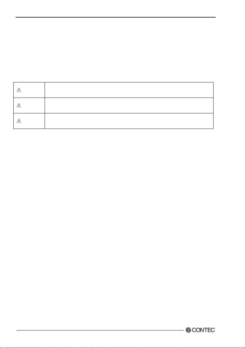
Safety Information
This document provides safety information using the following symbols to prevent accidents resulting
in injury or death and the destruction of equipment and resources. Understand the meanings of these
labels to operate the equipment safely.
DANGER
WAR NI NG
CAUTION
DANGER indicates an imminently hazardous situation which, if not avoided, will
result in death or serious injury.
WARNING indicates a potentially hazardous situation which, if not avoided, could
result in death or serious injury.
CAUTION indicates a potentially hazardous situation which, if not avoided, may
result in minor or moderate injury or in property damage.
DIO-3232T-PE, DI-64T-PE, DO-64T-PE
6
Page 14
1. Before Using the Product
Handling Precautions
DANGER
Do not use the product where it is exposed to flammable or corrosive gas. Doing so may result in
an explosion, fire, electric shock, or failure.
CAUTION
- There are switches on the board that need to be set in advance.
Be sure to check these before installing the board.
- Only set the switches and jumpers on the board to the specified settings.
Otherwise, the board may malfunction, overheat, or cause a failure.
- Do not strike or bend the board.
Otherwise, the board may malfunction, overheat, cause a failure or breakage.
- Do not touch the board's metal plated terminals (edge connector) with your hands.
Otherwise, the board may malfunction, overheat, or cause a failure.
If the terminals are touched by someone's hands, clean the terminals with industrial alcohol.
- Do not install or remove the board to or from the extension slot while the computer's power is turned
on. And also do not connect the board and external device while the power is turned on.
Otherwise, the board may malfunction, overheat, or cause a failure.
Be sure that the personal computer or the I/O extension unit power is turned off.
- Make sure that your PC or extension unit can supply ample power to all the boards installed.
Insufficiently energized boards could malfunction, overheat, or cause a failure.
- The specifications of this product are subject to change without notice for enhancement and quality
improvement.
Even when using the product continuously, be sure to read the manual and understand the contents.
- Do not modify the product. CONTEC will bear no responsibility for any problems, etc., resulting
from modifying this product.
- Regardless of the foregoing statements, CONTEC is not liable for any damages whatsoever
(including damages for loss of business profits) arising out of the use or inability to use this
CONTEC product or the information contained herein.
DIO-3232T-PE, DI-64T-PE, DO-64T-PE
7
Page 15
1. Before Using the Product
Environment
Use this product in the following environment. If used in an unauthorized environment, the board may
overheat, malfunction, or cause a failure.
Operating temperature
0 - 50°C
Humidity
10 - 90%RH (No condensation)
Corrosive gases
None
Floating dust particles
Not to be excessive
Inspection
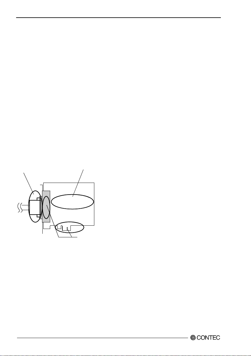
Inspect the product periodically as follows to use it safely.
- Check that the bus connector
of the board and its cable have
been plugged correctly.
- Check that the board has
no dust or foreign matter adhering.
- The gold-plated leads of the bus connector
have no stain or corrosion.
Storage
When storing this product, keep it in its original packing form.
(1) Put the board in the storage bag.
(2) Wrap it in the packing material, and then put it in the box.
(3) Store the package at room temperature at a place free from direct sunlight, moisture, shock,
vibration, magnetism, and static electricity.
Disposal
When disposing of the product, follow the disposal procedures stipulated under the relevant laws and
municipal ordinances.
DIO-3232T-PE, DI-64T-PE, DO-64T-PE
8
Page 16

2. Setup
2. Setup
This chapter explains how to set up the board.
What is Setup?
Setup means a series of steps to take before the product can be used.
Different steps are required for software and hardware.
The setup procedure varies with the OS and applications used.
Using the Board under Windows
Using the Driver Library API-PAC(W32)
This section describes the setup procedure to be performed before you can start developing application
programs for the board using the bundled CD-ROM “Driver Library API-PAC(W32)”.
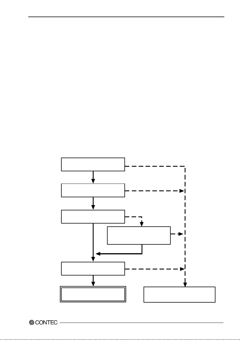
Taking the following steps sets up the software and hardware. You can use the diagnosis program later
to check whether the software and hardware function normally.
Step 1 Installing the Software
Step 2 Setting the Hardware
Step 3 Installing the Hardware
Step 4 Initializing the Software
Step 5 Checking Operations with the Diagnosis Program
If Setup fails to be performed normally, see the “Setup Troubleshooting” section at the end of this
chapter.
Using the Board under Windows
Using Software Other than the Driver Library API-PAC(W32)
For setting up software other than API-PAC(W32), refer to the manual for that software. See also the
following parts of this manual as required.
This chapter Step 2 Setting the Hardware
This chapter Step 3 Installing the Hardware
Chapter 3 External Connection
Chapter 6 About Hardware
DIO-3232T-PE, DI-64T-PE, DO-64T-PE
9
Page 17

2. Setup
Using the Board under an OS Other than Windows
For using the board under Linux, see the following parts of this manual.
This chapter Step 2 Setting the Hardware
Chapter 3 External Connection
Chapter 5 About Software
Chapter 6 About Hardware
For using the board under an OS other than Windows and Linux, see the following parts of this manual.
This chapter Step 2 Setting the Hardware
Chapter 3 External Connection
Chapter 6 About Hardware
DIO-3232T-PE, DI-64T-PE, DO-64T-PE
10
Page 18
2. Setup
Step 1 Installing the Software
This section describes how to install the Driver libraries.
Before installing the hardware on your PC, install the Driver libraries from the bundled API-PAC(W32)
CD-ROM.
The following description assumes the operating system as Windows XP. Although some user
interfaces are different depending on the OS used, the basic procedure is the same.
About the driver to be used
Two digital I/O drivers are available : API-DIO(WDM) and API-DIO(98/PC).
API-DIO(WDM) is a new driver to perform digital I/O under Windows.
API-DIO(WDM) was developed to improve the conventional product version of API-DIO(98/PC) in the
ease of use and functionality.
It is advisable to use API-DIO(WDM) for you to use an digital I/O device. API-DIO(WDM) will
support new OS and devices in the future but will not support Windows NT 4.0, Windows 95, ISA bus.
Use API-DIO(98/PC) if your operating environment contains such an unsupported piece of software or
hardware.
Check the following selection guide to easily select the driver to be used.
OS to be used
Windows Vista
Windows XP/Windows 2000
Device type
PCI bus, PC Card
Use the digital board for
the first time?
Ye s
Language to be used
VC.Net, VB.Net, VC#.Net
VC6, VB6
API-DIO(WDM)
DIO-3232T-PE, DI-64T-PE, DO-64T-PE
Windows Me/98/95
Windows NT 4.0
ISA Bus
Already used.
The existing system
upgrade using
API-DIO(98/PC)?
No
VC2, 4, 5, VB4, 5,
Delphi, C++Builder
Ye s
API-DIO(98/PC)
11
Page 19
2. Setup
Starting the Install Program
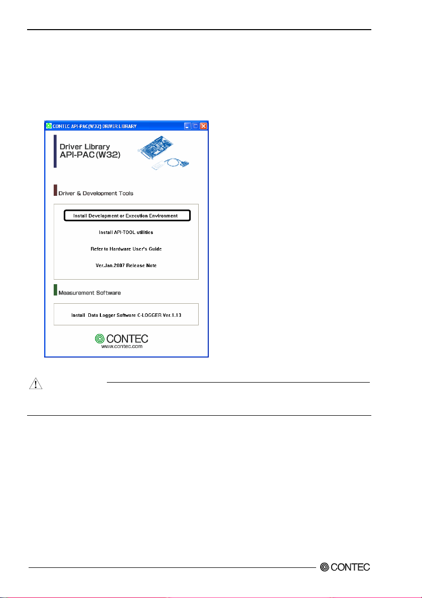
(1)
Load the CD-ROM [API-PAC(W32)] on your PC.
(2)
The API-PAC(W32) Installer window appears automatically.
If the panel does not appear, run (CD-ROM drive letter):\AUTORUN.exe.
(3)
Click on the [Install Development or Execution Environment] button.
* When using the Windows Vista, driver is automatically installed.
CAUTION
Before installing the software in Windows Vista, XP, Server 2003 and 2 000 , log in as a user with
administrator privileges.
DIO-3232T-PE, DI-64T-PE, DO-64T-PE
12
Page 20
2. Setup
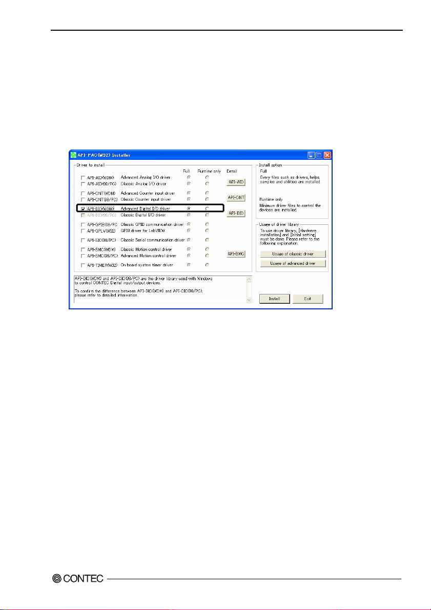
When Using API-DIO(WDM)
Selecting API-DIO(WDM)
(1)
The following dialog box appears to select “Driver to install” and “Install option”, “Usage of
driver library”.
(2)
Select the "Advanced Digital I/O driver".
(3)
Click on the [Install] button.
* Clicking the [API-DIO] button displays detailed information about API-DIO(WDM) and
API-DIO(98/PC).
Run the installation
(1)
Complete the installation by following the instructions on the screen.
(2)
The Readme file appears when the installation is complete.
DIO-3232T-PE, DI-64T-PE, DO-64T-PE
13
Page 21
2. Setup
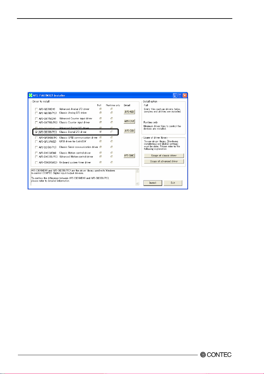
Whe n Us ing API-DIO(98/PC)
Selecting API-DIO(98/PC)
(1)
The following dialog box appears to select “Driver to install” and “Install option”, “Usage of
driver library”.
(2)
Select “Classic Digital I/O driver”.
(3)
Click on the [Install] button.
* Clicking on the [API-DIO] button displays detailed information on API-DIO(WDM),
API-DIO(98/PC).
DIO-3232T-PE, DI-64T-PE, DO-64T-PE
14
Page 22
2. Setup
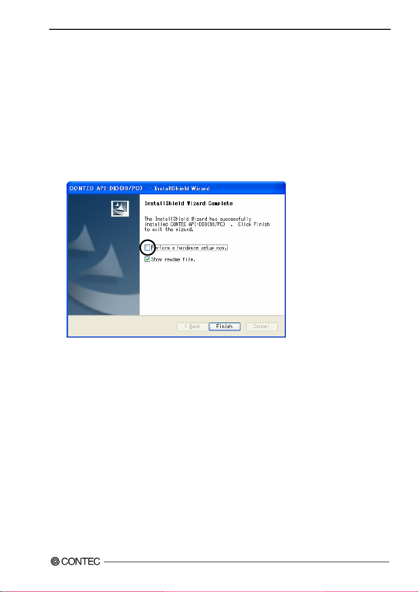
Executing the Installation
(1)
Follow the on-screen instructions to proceed to install.
(2) When the required files have been copied, the “Perform a hardware setup now(API-TOOL
Configuration)” and “Show readme file” check boxes are displayed.
When you are installing the software or hardware for the first time:
1) Uncheck “Perform a hardware setup now”.
2) Click on the [Finish] button.
Go to Step 2 to set and plug the hardware.
* When the hardware has already been installed:
Check “Perform a hardware setup now(API-TOOL Configuration)”, then go to Step 4
“Initializing the Software”.
You have now finished installing the software.
DIO-3232T-PE, DI-64T-PE, DO-64T-PE
15
Page 23

2. Setup
Step 2 Setting the Hardware
This section describes how to set the board and plug it on your PC.
The board has some switches to be preset.
Check the on-board switches before plugging the board into an extension slot.
The board can be set up even with the factory defaults untouched. You can change board settings later.
Parts of the Board and Factory Defaults
Figure 2.1. shows the names of major parts on the board.
Note that the switch setting shown below is the factory default.
- Interface connector
(CN1)
B48
B47
A48
A47
SW1
BOARD ID
- Board ID setting switch
(SW1)
SW1
BOARD ID
8
9
7
6
5
4
3
2
1
0
A
B
C
D
E
F
B02
B01
A02
A01
Figure 2.1. Component Locations
DIO-3232T-PE, DI-64T-PE, DO-64T-PE
16
Page 24

2. Setup
Setting the Board ID
If you install two or more boards on one personal computer, assign a different ID value to each of the
boards to distinguish them.
The board IDs can be set from 0 to Fh to identify up to sixteen boards.
If only one board is used, the original factory setting (Board ID = 0) should be used.
Setting Procedure
To set the board ID, use the rotary switch on the board. Turn the SW1 knob to set the board ID as
shown below.
SW1
BOARD ID
8
9
A
7
6
B
5
C
4
D
3
E
2
1
Figure 2.2. Board ID Settings (SW1)
F
0
Factory setting:
(Board ID = 0)
DIO-3232T-PE, DI-64T-PE, DO-64T-PE
17
Page 25

2. Setup
Plugging the Board
(1) Before plugging the board, shut down the system, unplug the power code of your PC.
(2) Remove the cover from the PC so that the board can be mounted.
(3) Plug the board into an extension slot.
(4) Attach the board bracket to the PC.
(5) Put the cover back into place.
CAUTION
- Do not touch the board's metal plated terminals (edge connector) with your hands.
Otherwise, the board may malfunction, overheat, or cause a failure.
If the terminals are touched by someone's hands, clean the terminals with industrial alcohol.
- Do not install or remove the board to or from the slot while the computer's or expansion unit’s power is
turned on.
Otherwise, the board may malfunction, overheat, or cause a failure.
Be sure that the personal computer power is turned off.
- Make sure that your PC or expansion unit can supply ample power to all the boards installed.
Insufficiently energized boards could malfunction, overheat, or cause a failure.
DIO-3232T-PE, DI-64T-PE, DO-64T-PE
18
Page 26

2. Setup
Step 3 Installing the Hardware
For using an extension board under Windows, you have to let the OS detect the I/O addresses and IRQ
to be used by the board. The process is referred to as installing the hardware.
In the case of using two or more boards, make sure you install one by one with the Found New
Hardware Wizard.
Turning on the PC
Turn on the power to your PC.
CAUTION
- The board cannot be properly installed unless the resources (I/O addresses and interrupt level) for
the board can be allocated. Before attempting to install the board, first determine what PC
resources are free to use.
- The resources used by each board do not depend on the location of the PCI Express bus slot or the
board itself. If you remove two or more boards that have already been installed and then remount
one of them on the computer, it is unknown that which one of the sets of resources previously
assigned to the two boards is assigned to the remounted board. In this case, you must check the
resource settings.
When Using API-DIO(WDM)
(1) The “Found New Hardware Wizard” will be started.
Select “No, not this time” and then click the “Next” button.
DIO-3232T-PE, DI-64T-PE, DO-64T-PE
19
Page 27

2. Setup
(2) When “Multimedia Controller” is displayed, select “Install from a list or s
location[Advanced]” and then specify that folder on the CD-ROM which contains the setup
information (INF) file to register the board.
When the model name of hardware is displayed, select “Install the software automatically
[Recommended]” and then click on the “Next” button.
Source folder
The setup information (INF) file is contained in the following folder on the bundled CD-ROM.
Windows Vista, XP, Server 2003, 2000 \INF\Wdm\Dio
pecific
\INF\Wdm\Dio
DIO-3232T-PE, DI-64T-PE, DO-64T-PE
20
Page 28

2. Setup
* The name of the board
you have just added is
displayed.
- DIO-3232T-PE
- DI-64T-PE
- DO-64T-PE
You have now finished installing the hardware.
DIO-3232T-PE, DI-64T-PE, DO-64T-PE
21
Page 29

2. Setup
When Using API-DIO(98/PC)
(1) The “Found New Hardware Wizard” will be started.
Select “No, not this time” and then click the “Next” button.
(2) Select “Install from a list or s
pecific location[Advanced]” and then click the “Next” button.
DIO-3232T-PE, DI-64T-PE, DO-64T-PE
22
Page 30

2. Setup
(3) Specify that folder on the CD-ROM which contains the setup information (INF) file to register the
board.
* The name of the board
you have just added is
displayed.
- DIO-3232T-PE
- DI-64T-PE
- DO-64T-PE
Source folder
The setup information (INF) file is contained in the following folder on the bundled CD-ROM.
Windows Vista, XP, Server 2003, 2000 \INF\Win2000\Dio\PCI
Example of specifying the folder for use under Windows XP
DIO-3232T-PE, DI-64T-PE, DO-64T-PE
\INF\Win2000\Dio\PCI
23
Page 31

2. Setup
CAUTION
In Windows XP, the Hardware Wizard displays the following alert dialog box when you have
located the INF file. This dialog box appears, only indicating that the relevant driver has not
passed Windows Logo testing, and it can be ignored without developing any problem with the
operation of the board.
In this case, click on the [Continue Anyway] button.
You have now finished installing the hardware.
* The name of the board
you have just added is
displayed.
- DIO-3232T-PE
- DI-64T-PE
- DO-64T-PE
DIO-3232T-PE, DI-64T-PE, DO-64T-PE
24
Page 32

2. Setup
Step 4 Initializing the Software
The driver function library requires the initial setting to recognize the execution environment. It is
called the initialization of the Driver library.
When Using API-DIO(WDM)
API-DIO(WDM) is initialized automatically during hardware installation. Therefore, if you want to
use it with its initial settings, you can skip the setting procedure described in Step 4. To change the
device name, follow the setting procedure shown below.
Setting the device name
(1) Run Device Manager. From [My Computer] - [Control Panel], select [System] and then select the
[Device Manager] tab.
(You can also open Device Manager by right clicking on My Computer and selecting Properties.)
* The name of the board
you have just added is
displayed.
- DIO-3232T-PE
- DI-64T-PE
- DO-64T-PE
(2) The installed hardware appears under the CONTEC Devices node. Open the CONTEC Devices
node and select the device you want to setup (the device name should appear highlighted). Click
[Properties].
DIO-3232T-PE, DI-64T-PE, DO-64T-PE
25
Page 33

2. Setup
(3) The proper t y page for the device opens.
Enter the device name in the common settings tab page and then click [OK].
The device name you set here is used later when programming.
* The initial device name that appears is a default value. You can use this default name if you wish.
* Make sure that you do not use the same name for more than one device.
You have now finished installing the initial setting of Software.
DIO-3232T-PE, DI-64T-PE, DO-64T-PE
26
Page 34

2. Setup
Whe n Us ing API-DIO(98/PC)
(1) Open the Start Menu, then select “Programs” – “CONTEC API-PAC(W32)” – “API-TOOL
Configuration”.
(2) API-TOOL Configuration detects boards automatically.
The detected boards are listed.
Updating the Settings
(1) Select “Save setting to registry…” from the “File” menu.
You have now finished installing the initial setting of Software.
DIO-3232T-PE, DI-64T-PE, DO-64T-PE
27
Page 35

2. Setup
Step 5 Checking Operations with the Diagnosis Program
Use the diagnosis program to check that the board and driver software work normally, thereby you can
confirm that they have been set up correctly.
What is the Diagnosis Program?
The diagnosis program diagnoses the states of the board and driver software.
It can also be used as a simple checker when an external device is actually connected.
Using the “Diagnosis Report” feature reports the driver settings, the presence or absence of the board,
I/O status, and interrupt status.
Check Method
Connect the board to a remote device to test the input/output and check the execution environment.
For this board, an external power supply is not required.
The Check Mate (CM-64(PC)E) comes in handy when you check d igital I/O bo ard s .
Check the board with the factor defaults untouched.
Connection diagram
Connector
Board
Optional cable
PCB96PS-xxP or PCB-96P-1.5
To connect a device other than the Check Mate, see Chapter 3 “External Connection”.
CM-64(PC)E
GROUP 1
7 6 5 4 3 2 1 0
GROUP 3
7 6 5 4 3 2 1 0
GROUP 5
7 6 5 4 3 2 1 0
GROUP 7
7 6 5 4 3 2 1 0
ACK
GROUP 0
7 6 5 4 3 2 1 0
GROUP 2
7 6 5 4 3 2 1 0
GROUP 4
7 6 5 4 3 2 1 0
GROUP 6
7 6 5 4 3 2 1 0
STB
POWER
CN3
DIO-3232T-PE, DI-64T-PE, DO-64T-PE
28
Page 36

2. Setup
Using the Diagnosis Program
Starting the Diagnosis Program for Use of API-DIO(WDM)
Click the [Diagnosis] button on the device property page to start the diagnosis program.
DIO-3232T-PE, DI-64T-PE, DO-64T-PE
29
Page 37

2. Setup
Starting the Diagnosis Program for Use of API-DIO(98/PC)
Select the board in the API-TOOL Configuration windows, then run the Diagnosis Program. Follow
the instructions on screen.
* The name of the board you have just added is displayed.
* The name of the board
you have just added is
displayed.
- DIO-3232T-PE
- DI-64T-PE
- DO-64T-PE
DIO-3232T-PE, DI-64T-PE, DO-64T-PE
30
Page 38

2. Setup
Checking Digital Inputs and Outputs
The main panel of the Diagnosis Program appears.
You can check the current operation states of the board in the following boxes:
“Input Port” : Displays input values bit by bit at fixed time intervals.
“Output Port” : Mouse operation allows the data to output or display.
“Interrupt” : Displays the number of interrupts detected bit by bit.
* The name of the board
you have just added is
displayed.
- DIO-3232T-PE
- DI-64T-PE
- DO-64T-PE
To use the wait time control feature, click on the [Wait Configuration] button. Use the feature when
the wait time based on the DioWait or DioWaitEx function is not normal.
To use the function execution time measurement feature, click on the [Measurement Time] button.
Enter the I/O start port and the number of ports, then press the measurement button. The time for each
execution of a function will be measured.
DIO-3232T-PE, DI-64T-PE, DO-64T-PE
31
Page 39

2. Setup
Diagnosis Report
(1) Clicking on the [Show Diagnosis Report] button displays detailed data such as board settings and
the diagnosis results while saving them in text format.
When it is API-DIO(WDM), file name to save the result is displayed.
When it is API-DIO(98/PC), the result is saved to the folder in which to install (Program
Files\CONTEC\API-PAC(W32)) by the text file (DioRep.txt) and then displayed.
The Diagnosis Program performs “board presence/absence check”, “driver file test”, “board setting
test”, and so on.
CAUTION
Before executing diagnosis report output, unplug the cable from the board.
* The name of the board
you have just added is
displayed.
- DIO-3232T-PE
- DI-64T-PE
- DO-64T-PE
(2) A diagnosis report is displayed as shown below.
* The name of the board
you have just added is
displayed.
- DIO-3232T-PE
- DI-64T-PE
- DO-64T-PE
DIO-3232T-PE, DI-64T-PE, DO-64T-PE
32
Click on [Show
Diagnosis Report].
Page 40

2. Setup
Setup Troubleshooting
Symptoms and Actions
No output can be obtained.
Use API-TOOL Configuration to check whether the board name setting is wrong.
The board works with the Diagnosis Program but not with an application.
The Diagnosis Program is coded with API-TOOL functions. As long as the board operates with the
Diagnosis Program, it is to operate with other applications as well. In such cases, review your program
while paying attention to the following points:
- Check the arguments to functions and their return values.
- When the board is an isolated type, it has a time lag for its response between the output by a
function and the actual output. Consider the execution intervals between functions.
The OS won’t normally get started or detect the board.
[Windows Vista, XP, Server 2003, 2000]
Turn off the power to your PC, then unplug the board . Restart the OS and delete the board settings of
API-TOOL Configuration. Turn off the PC again, plug the board, and restart the OS. Let the OS
detect the board and use API-TOOL Configuration to register board settings.
If your problem cannot be resolved
Contact your retailer.
DIO-3232T-PE, DI-64T-PE, DO-64T-PE
33
Page 41

2. Setup
DIO-3232T-PE, DI-64T-PE, DO-64T-PE
34
Page 42

3. External Connection
3. External Connection
This chapter describes the interface connectors on the board and the external I/O circuits.
Check the information available here when connecting an external device.
How to connect the connectors
Connector shape
The on-board interface connector (CN1) is used when connecting this product and the external devices.
Interface connector (CN1)
B48
B47
B02
B01
* Please refer to chapter 1 for more information on the supported cable and accessories.
- Connector used
A48
PCR-E96LMD+equivalent to it
A47
[mfd. by HONDA TSUSHIN
KOGYO CO., LTD.]
- Applicable connec tors
PCR-E96FA+equivalent to it
[mfd. by HONDA TSUSHIN
A02
A01
KOGYO CO., LTD.]
Figure 3.1. Interface Connector (CN1) Shape
DIO-3232T-PE, DI-64T-PE, DO-64T-PE
35
Page 43

3. External Connection
Connector Pin Assignment
Pin Assignments of DIO-3232T-PE Interface Connector (CN1)
Vcc B48 A48 Vcc
+5V
Vcc B47 A47 Vcc
O-77 B46 A46 I -37
O-76 B45 A45 I -36
O-75 B44 A44 I -35
O-74 B43 A43 I -34
+7 port
(Output)
O-73 B42 A42 I -33
O-72 B41 A41 I -32
O-71 B40 A40 I -31
O-70 B39 A39 I -30
O-67 B38 A38 I -27
O-66 B37 A37 I -26
O-65 B36 A36 I -25
O-64 B35 A35 I -24
+6 port
(Output)
O-63 B34 A34 I -23
O-62 B33 A33 I -22
O-61 B32 A32 I -21
O-60 B31 A31 I -20
GND B30 A30 GND
Signal
common
GND B29 A29 GND
N.C. B28 A28 N.C.
N.C. B27 A27 N.C.
N.C. B26 A26 N.C.
N.C. B25 A25 N.C.
N.C.
N.C. B24 A24 N.C.
N.C. B23 A23 N.C.
N.C. B22 A22 N.C.
N.C. B21 A21 N.C.
Vcc B20 A20 Vcc
+5V
Vcc B19 A19 Vcc
O-57 B18 A18 I-1 7
O-56 B17 A17 I-1 6
O-55 B16 A16 I-1 5
O-54 B15 A15 I-1 4
+5 port
(Output)
O-53 B14 A14 I-1 3
O-52 B13 A13 I-1 2
O-51 B12 A12 I-1 1
O-50 B11 A11 I-1 0
O-47 B10 A10 I-0 7
O-46 B09 A09 I-0 6
O-45 B08 A08 I-0 5
O-44 B07 A07 I-0 4
+4 port
(Output)
O-43 B06 A06 I-0 3
O-42 B05 A05 I-0 2
O-41 B04 A04 I-0 1
O-40 B03 A03 I-0 0
GND B02 A02 GND
Signal
common
GND B01
[49]
[1]
B48 A48
B01
[96]
[48]
A01
A01 GND
- [ ] shows the pin numbers specified by HONDA TSUSHIN KOGYO CO., LTD.
I-00 - I-37
O-40 - O-77
Vcc
GND
N.C.
32 input signal pins. Connect output signals from the external device to these pins.
32 output signal pins. Connect these pins to the input signal pins of the external device.
Output +5V. Max. electrical current is 350mA.
This pin is connected to the slot’s GND.
This pin is left unconnected.
Figure 3.2. Pin Assignments of Interface Connector (CN1) < DIO-3232T-PE >
+5V
+3 port
(Input)
+2 port
(Input)
Signal
common
N.C.
+5V
+1 port
(Input)
+0 port
(Input)
Signal
common
DIO-3232T-PE, DI-64T-PE, DO-64T-PE
36
Page 44

3. External Connection
Pin Assignments of DI-64T-PE Interface Connector (CN1)
Vcc B48 A48 Vcc
+5V
Vcc B47 A47 Vcc
B46 A46 I-37
I-77
B45 A45 I-36
I-76
B44 A44 I-35
I-75
B43 A43 I-34
I-74
+7 port
(Input)
+6 port
(Input)
Signal
common
N.C.
+5V
+5 port
(Input)
+4 port
(Input)
Signal
common
B42 A42 I-33
I-73
B41 A41 I-32
I-72
B40 A40 I-31
I-71
B39 A39 I-30
I-70
B38 A38 I-27
I-67
B37 A37 I-26
I-66
B36 A36 I-25
I-65
B35 A35 I-24
I-64
I-63
I-62
I-61
I-60
GND B30 A30 GND
GND B29 A29 GND
N.C. B28 A28 N.C.
N.C. B27 A27 N.C.
N.C. B26 A26 N.C.
N.C. B25 A25 N.C.
N.C. B24 A24 N.C.
N.C. B23 A23 N.C.
N.C. B22 A22 N.C.
N.C. B21 A21 N.C.
Vcc B20 A20 Vcc
Vcc B19 A19 Vcc
I-57
I-56
I-55
I-54
I-53
I-52
I-51
I-50
I-47
I-46
I-45
I-44
I-43
I-42
I-41
I-40
GND B02 A02 GND
GND B01
[49]
B48 A48
B34 A34 I-23
B33 A33 I-22
B32 A32 I-21
B31 A31 I-20
B18 A18 I-17
B17 A17 I-16
B16 A16 I-15
B01
B15 A15 I-14
[96]
B14 A14 I-13
B13 A13 I-12
B12 A12 I-11
B11 A11 I-10
B10 A10 I-07
B09 A09 I-06
B08 A08 I-05
B07 A07 I-04
B06 A06 I-03
B05 A05 I-02
B04 A04 I-01
B03 A03 I-00
[1]
A01
[48]
A01 GND
+5V
+3 port
(Input)
+2 port
(Input)
Signal
common
N.C.
+5V
+1 port
(Input)
+0 port
(Input)
Signal
common
* I-00 - I-37 can be used as interrupt signal.
* The numbers in square brackets [ ] are pin numbers designated by HONDA TSUSHIN KOGYO CO., LTD.
I-00 - I-77 64 input signal pins. Connect output signals from the external device to these pins.
Vcc Output +5V. Max. electrical current is 350mA.
GND This pin is connected to GND in the slot.
N.C. This pin is left unconnected.
Figure 3.3. Pin Assignments of Interface Connector (CN1) < DI-64T-PE >
DIO-3232T-PE, DI-64T-PE, DO-64T-PE
37
Page 45

3. External Connection
Pin Assignments of DO-64T-PE Interface Connector (CN1)
Vcc B48 A48 Vcc
Signal
common
Vcc B47 A47 Vcc
B46 A46
O-77
B45 A45
O-76
B44 A44
O-75
B43 A43
O-74
+7 port
(Output)
+6 port
(Output)
Signal
common
N.C.
Signal
common
+5 port
(Output)
+4 port
(Output)
Signal
common
B42 A42
O-73
B41 A41
O-72
B40 A40
O-71
B39 A39
O-70
B38 A38
O-67
B37 A37
O-66
B36 A36
O-65
B35 A35
O-64
O-63
O-62
O-61
O-60
GND B30 A30 GND
GND B29 A29 GND
N.C. B28 A28 N.C.
N.C. B27 A27 N.C.
N.C. B26 A26 N.C.
N.C. B25 A25 N.C.
N.C. B24 A24 N.C.
N.C. B23 A23 N.C.
N.C. B22 A22 N.C.
N.C. B21 A21 N.C.
Vcc B20 A20 Vcc
Vcc B19 A19 Vcc
O-57
O-56
O-55
O-54
O-53
O-52
O-51
O-50
O-47
O-46
O-45
O-44
O-43
O-42
O-41
O-40
GND B02 A02 GND
GND B01
[49]
B48 A48
B34 A34
B33 A33
B32 A32
B31 A31
B18 A18
B17 A17
B16 A16
B01
B15 A15
[96]
B14 A14
B13 A13
B12 A12
B11 A11
B10 A10
B09 A09
B08 A08
B07 A07
B06 A06
B05 A05
B04 A04
B03 A03
[1]
A01
[48]
A01 GND
O-37
O-36
O-35
O-34
O-33
O-32
O-31
O-30
O-27
O-26
O-25
O-24
O-23
O-22
O-21
O-20
O-17
O-16
O-15
O-14
O-13
O-12
O-11
O-10
O-07
O-06
O-05
O-04
O-03
O-02
O-01
O-00
Signal
common
+3 port
(Output)
+2 port
(Output)
Signal
common
N.C.
Signal
common
+1 port
(Output)
+0 port
(Output)
Signal
common
The numbers in square brackets [ ] are pin numbers designated by HONDA TSUSHIN KOGYO CO., LTD.
O-00 - O-77 64 output signal pins. Connect these pins to the input signal pins of the external device.
Vcc Output +5V. Max. electrical current is 350mA..
GND This pin is connected to GND in the slot.
N.C. This pin is left unconnected.
Figure 3.4. Pin Assignments of Interface Connector (CN1) < DO-64T-PE >
DIO-3232T-PE, DI-64T-PE, DO-64T-PE
38
Page 46

3. External Connection
Pin Assignments of PCB96WS or CCB-96
The figure below shows the correspondence between the option cable pins and signals.
< Pin assignments for connecting a PCB-96WS or CCB-96 to the DIO-3232T-PE >
- "Optional cable PCB96PS"
- Optional cable PCB96WS
A
+ "Connector conversion board CCB-96"
Connector DCLC-J37SAF-20L9
or equivalence to it (mfd by JAE)
B
+5V Vcc 37 19 N.C. +5V Vcc 37 19 N.C.
I-37 36 18 Vcc +5V O-77 36 18 Vcc +5V
I-36 35 17 I-17 O-76 35 17 O-57
I-35 34 16 I-16 O-75 34 16 O-56
I-34 33 15 I-15 O-74 33 15 O-55
+3 port
(Input)
I-33 32 14 I-14 O-73 32 14 O-54
I-32 31 13 I-13 O-72 31 13 O-53
I-31 30 12 I-12 O-71 30 12 O-52
I-30 29 11 I-11
I-27 28 10 I-10
I-26 27 9 I-07 O-66 27 9 O-47
I-25 26 8 I-06 O-65 26 8 O-46
I-24 25 7 I-05 O-64 25 7 O-45
+2 port
(Input)
I-23 24 6 I-04 O-63 24 6 O-44
I-22 23 5 I-03 O-62 23 5 O-43
I-21 22 4 I-02 O-61 22 4 O-42
I-20 21 3 I-01
Signal
GND 20 2 I-00
common
CNA of PCB96WS
CN3(CNA) of CCB96
37
20
19
1
1 GND
+1 port
(Input)
+0 port
(Input)
Signal
common
+7 port
(Output)
O-70 29 11 O-51
O-67 28 10 O-50
+6 port
(Output)
O-60 21 3 O-41
Signal
GND 20 2 O-40
common
CCB-96
CNB of PCB96WS
CN4(CNB) of CCB96
37
20
19
(Output)
(Output)
1
1 GND
common
Figure 3.5. PCB96WS or CCB-96 Signal Assignments < DIO-3232T-PE >
+5 port
+4 port
Signal
DIO-3232T-PE, DI-64T-PE, DO-64T-PE
39
Page 47

3. External Connection
< Pin assignments for connecting a PCB-96WS or CCB-96 to the DI-64T-PE >
- "Optional cable PCB96PS"
- Optional cable PCB96WS
A
+ "Connector conversion board CCB-96"
Connector DCLC-J37SAF-20L9
or equivalence to it (mfd by JAE)
B
+5V Vcc 37 19 N.C. +5V Vcc 37 19 N.C.
I-37 36 18 Vcc +5V I-77 36 18 Vcc +5V
I-36 35 17 I-17 I-76 35 17 I-57
I-35 34 16 I-16 I-75 34 16 I-56
I-34 33 15 I-15 I-74 33 15 I-55
+3 port
(Input)
I-33 32 14 I-14 I-73 32 14 I-54
I-32 31 13 I-13 I-72 31 13 I-53
I-31 30 12 I-12 I-71 30 12 I-52
I-30 29 11 I-11
I-27 28 10 I-10
I-26 27 9 I-07 I-66 27 9 I-47
I-25 26 8 I-06 I-65 26 8 I-46
I-24 25 7 I-05 I-64 25 7 I-45
+2 port
(Input)
I-23 24 6 I-04 I-63 24 6 I-44
I-22 23 5 I-03 I-62 23 5 I-43
I-21 22 4 I-02 I-61 22 4 I-42
I-20 21 3 I-01
Signal
GND 20 2 I-00
common
CNA of PCB96WS
CN3(CNA) of CCB96
37
20
19
1
1 GND
+1 port
(Input)
+0 port
(Input)
Signal
common
+7 port
(Input)
I-70 29 11 I-51
I-67 28 10 I-50
+6 port
(Input)
I-60 21 3 I-41
Signal
GND 20 2 I-40
common
CCB-96
CNB of PCB96WS
CN4(CNB) of CCB96
37
20
19
1
1 GND
Figure 3.6. PCB96WS or CCB-96 Signal Assignments < DI-64T-PE >
+5 port
(Input)
+4 port
(Input)
Signal
common
DIO-3232T-PE, DI-64T-PE, DO-64T-PE
40
Page 48

3. External Connection
< Pin assignments for connecting a PCB-96WS or CCB-96 to the DO-64T-PE >
- "Optional cable PCB96PS"
- Optional cable PCB96WS
A
+ "Connector conversion board CCB-96"
Connector DCLC-J37SAF-20L9
or equivalence to it (mfd by JAE)
B
+5V Vcc 37 19 N.C. +5V Vcc 37 19 N.C.
O-37 36 18 Vcc +5V O-77 36 18 Vcc +5V
O-36 35 17 O-17 O-76 35 17 O-57
O-35 34 16 O-16 O-75 34 16 O-56
O-34 33 15 O-15 O-74 33 15 O-55
+3 port
(Output)
O-33 32 14 O-14 O-73 32 14 O-54
O-32 31 13 O-13 O-72 31 13 O-53
O-31 30 12 O-12 O-71 30 12 O-52
O-30 29 11 O-11
O-27 28 10 O-10
O-26 27 9 O-07 O-66 27 9 O-47
O-25 26 8 O-06 O-65 26 8 O-46
O-24 25 7 O-05 O-64 25 7 O-45
+2 port
(Outnput)
O-23 24 6 O-04 O-63 24 6 O-44
O-22 23 5 O-03 O-62 23 5 O-43
O-21 22 4 O-02 O-61 22 4 O-42
O-20 21 3 O-01
Signal
GND 20 2 O -00
common
CNA of PCB96WS
CN3(CNA) of CCB96
37
20
19
1
1 GND
+1 port
(Output)
+0 port
(Output)
Signal
common
+7 port
(Output)
O-70 29 11 O-51
O-67 28 10 O-50
+6 port
(Output)
O-60 21 3 O-41
Signal
GND 20 2 O-40
common
CCB-96
CNB of PCB96WS
CN4(CNB) of CCB96
37
20
19
1
1 GND
Figure 3.7. PCB96WS or CCB-96 Signal Assignments < DO-64T-PE >
+5 port
(Output)
+4 port
(Output)
Signal
common
DIO-3232T-PE, DI-64T-PE, DO-64T-PE
41
Page 49

3. External Connection
Relationships between API-PAC(W32) Logical Ports/Bits and Connector Signal Pins
The following table lists the relationships between the connector signal pins and the logical port/bit
numbers used for I/O functions when applications are written with API-PAC(W32).
CAUTION
The logical port and logical bit numbers are virtual port and bit numbers that enable programming
independent of board I/O addresses or board types.
For details, refer to API-DIO HELP available after installing API-PAC(W32).
DIO-3232T-PE
Table 3.1. Logical Ports, Logical Bits, and Connector Signal Pins
Input logical port 0
Input logical port 1
Input logical port 2
Input logical port 3
Output logical port 0
Output logical port 1
Output logical port 2
Output logical port 3
Notes : I-xx / O-xx represents an input / output signal.
[xx] represents the logical bit.
D7 D6 D5 D4 D3 D2 D1 D0
I-07
I-06
I-05
I-04
I-03
I-02
I-01
[7]
[6]
[5]
[4]
[3]
[2]
I-17
I-16
I-15
I-14
I-13
[15]
[14]
[13]
[12]
I-27
I-26
I-25
[23]
[22]
I-37
I-36
[31]
[30]
D7 D6 D5 D4 D3 D2 D1 D0
O-47
O-46
[7]
[6]
O-37
O-36
[15]
[14]
O-57
O-56
[23]
[22]
O-37
O-36
[31]
[30]
[21]
I-35
[29]
O-45
[5]
O-35
[13]
O-55
[21]
O-35
[29]
I-24
[20]
I-34
[28]
O-44
[4]
O-34
[12]
O-54
[20]
O-34
[28]
[11]
I-23
[19]
I-33
[27]
O-43
[3]
O-33
[11]
O-53
[19]
O-33
[27]
I-12
[10]
I-22
[18]
I-32
[26]
O-42
[2]
O-52
[10]
O-22
[18]
O-32
[26]
[1]
I-11
[9]
I-21
[17]
I-31
[25]
O-41
[1]
O-51
[9]
O-21
[17]
O-31
[25]
I-00
[0]
I-10
[8]
I-20
[16]
I-30
[24]
O-40
[0]
O-50
[8]
O-20
[16]
O-30
[24]
DIO-3232T-PE, DI-64T-PE, DO-64T-PE
42
Page 50

3. External Connection
DI-64T-PE
Table 3.2. Logical Ports, Logical Bits, and Connector Signal Pins < DI-64T-PE >
D7 D6 D5 D4 D3 D2 D1 D0
I-07
I-06
I-05
I-04
I-03
I-02
I-01
Input logical port 0
Input logical port 1
Input logical port 2
Input logical port 3
Input logical port 4
Input logical port 5
Input logical port 6
Input logical port 7
[xx] represents the logical bit.
[7]
[6]
[5]
[4]
I-17
I-16
I-15
[15]
[14]
I-27
I-26
[23]
[22]
I-37
I-36
[31]
[30]
I-47
I-46
[39]
[38]
I-57
I-56
[47]
[46]
I-67
I-66
[55]
[54]
I-77
I-76
[63]
[62]
Notes : I-xx represents an input signal.
[13]
I-25
[21]
I-35
[29]
I-45
[37]
I-55
[45]
I-65
[53]
I-75
[61]
I-14
[12]
I-24
[20]
I-34
[28]
I-44
[36]
I-54
[44]
I-64
[52]
I-74
[60]
[3]
I-13
[11]
I-23
[19]
I-33
[27]
I-43
[35]
I-53
[43]
I-63
[51]
I-73
[59]
[2]
I-12
[10]
I-22
[18]
I-32
[26]
I-42
[34]
I-52
[42]
I-62
[50]
I-72
[58]
[1]
I-11
[9]
I-21
[17]
I-31
[25]
I-41
[33]
I-51
[41]
I-61
[49]
I-71
[57]
I-00
[0]
I-10
[8]
I-20
[16]
I-30
[24]
I-40
[32]
I-50
[40]
I-60
[48]
I-70
[56]
DO-64T-PE
Table 3.3. Logical Ports, Logical Bits, and Connector Signal Pins < DO-64T-PE >
D7 D6 D5 D4 D3 D2 D1 D0
O-07
O-06
O-05
O-04
O-03
O-02
O-01
Output logical port 0
Output logical port 1
Output logical port 2
Output logical port 3
Output logical port 4
Output logical port 5
Output logical port 6
Output logical port 7
[xx] represents the logical bit.
[7]
[6]
[5]
[4]
O-17
O-16
O-15
O-14
[15]
[14]
[13]
[12]
O-27
O-26
O-25
[23]
[22]
O-37
O-36
[31]
[30]
O-47
O-46
[39]
[38]
O-57
O-56
[47]
[46]
O-67
O-66
[55]
[54]
O-77
O-76
[63]
Notes : O-xx represents an output signal.
[62]
[21]
O-35
[29]
O-45
[37]
O-55
[45]
O-65
[53]
O-75
[61]
O-24
[20]
O-34
[28]
O-44
[36]
O-54
[44]
O-64
[52]
O-74
[60]
[3]
O-13
[11]
O-23
[19]
O-33
[27]
O-43
[35]
O-53
[43]
O-63
[51]
O-73
[59]
[2]
O-12
[10]
O-22
[18]
O-32
[26]
O-42
[34]
O-52
[42]
O-62
[50]
O-72
[58]
[1]
O-11
[9]
O-21
[17]
O-31
[25]
O-41
[33]
O-51
[41]
O-61
[49]
O-71
[57]
O-00
[0]
O-10
[8]
O-20
[16]
O-30
[24]
O-40
[32]
O-50
[40]
O-60
[48]
O-70
[56]
DIO-3232T-PE, DI-64T-PE, DO-64T-PE
43
Page 51

3. External Connection
Connecting Input Signals
Input Circuit
Board
Vcc
PolySwitch
10kΩ
3.3V
SN74LVT245B
* I-xx represents an input pin.
One polyswitch is connected for Vcc(+5V) terminal.
+5V output
Input pin
Signal
common
Figure 3.8. Input Circuit < DIO-3232T-PE >, < DI-64T-PE >
The input circuit of interface is illustrated in Figure 3.8.
External digital signals given to signal inputs are TTL levels. The individual input signals are passed
to the personal computer as negative logic signals. As each of the signal inputs is pulled up internally,
the output of a relay contact or semiconductor switch can be connected directly between the signal input
and the signal common pin.
External device
Vcc
GNDGND
Connecting a Switch
I-00 (CN1 : A03 pin)
Board
GND (CN1 : A01 pin)
When the switch is ON, the corresponding bit contains 1.
When the switch is OFF, by contrast, the bit contains 0.
Figure 3.9. An Example to use Input I-00 < DIO-3232T-PE >, < DI-64T-PE >
DIO-3232T-PE, DI-64T-PE, DO-64T-PE
44
Switch
Page 52

3. External Connection
Connecting Output Signals
Output Circuit
Vcc
Board
External device
Vcc
Un-connected
74LS07
(Open-collector)
PolySwitch
+5V output
Output pin
Signal
commmon
10k
Ω
GNDGND
* O-xx represents an output pin.
One polyswitch is connected for Vcc(+5V) terminal.
Figure 3.10. Output Circuit < DIO-3232T-PE >, < DO-64T-PE >
The output circuit of interface is illustrated in Figure 3.10. Signal outputs are open-collector outputs;
individual output signals are sent to the external device as negative logic signals. Note that each signal
output must be pulled up at the external device as it is not pulled up internally.
CAUTION
When the PC is turned on, all output are reset to OFF.
Connection to the LED
Vcc (CN1 : B47 pin)
2k
Ω
Board side
O-40 (CN1 : B03 pin)
LED
When "1" is output to a relevant bit, the corresponding LED comes on.
When "0" is output to the bit, in contrast, the LED goes out.
Figure 3.11 An Example to use Output O-40 < DIO-3232T-PE >, < DO-64T-PE >
DIO-3232T-PE, DI-64T-PE, DO-64T-PE
45
Page 53

3. External Connection
Surge Protection
When connecting to digital outputs a load that may generate a voltage surge or current, for example an
inductive load such as a relay coil or incandescent lamp, suitable protection measures are required to
prevent damage to the output stage or malfunction owing to noise. The instantaneous interruption of
current flowing through a coil, including a relay, results in the sudden generation of a high-voltage pulse.
If the voltage exceeds the withstand voltage of the transistor, the transistor performance may be
degraded or the transistor may be damaged. To prevent this, be sure to connect a surge absorption
element when driving an inductive load including a relay coil. Examples of measures against voltage
surge are shown in Figure 3.12. below.
Examples of use of relay coil
+5V
Diode
Output pin
Signal common
Examples of use of lump
+5V
Output pin
Signal common
Relay
coil
Surge current
prevention
resistor
+5V
Relay
Output pin
Signal common
External power voltage < Zener diode voltage
+5V
Output pin
Signal common
coil
Zener diode
Resistor
Figure 3.12. Samples of Voltage Surge Protection
CAUTION
The protection circuit must be installed less than 50 cm from the load and contact to provide
effective protection.
A Protection Function of the +5V Outputs
A protection function, which prevents excessive current flow from the +5V outputs, is attached to this
board. In case of accidental short of the +5V output and GND, for example, the function works, and
the board operation may become impossible temporarily. In such a case, you should turn the PC off
and wait for several minutes before you use the board again.
DIO-3232T-PE, DI-64T-PE, DO-64T-PE
46
Page 54

4. Function
4. Function
This section describes the features of the board.
Each function described here can be easily set and executed by using the bundled API function library.
For details, refer to API-DIO HELP available after installation.
Data I/O Function
Data Input
When input data is “ON”, “1” is input to the relevant bit.
When the input data is “OFF”, in contrast, “0” is input to the relevant bit
Data Output
When “1” is output to the relevant bit, the corresponding transistor is set to “ON”.
When “0” is output to the relevant bit, in contrast, the corresponding transistor is set to “OFF”.
CAUTION
When the PC is turned on, all output are reset to 0 (OFF).
Monitoring Output Data
The <DIO-3232T-PE>, <DO-64T-PE> can read the state of the data currently being output without
affecting the output data.
DIO-3232T-PE, DI-64T-PE, DO-64T-PE
47
Page 55

4. Function
Digital Filter Function
Using this feature, the <DIO-3232T-PE>, <DI-64T-PE> can apply a digital filter to every input pin,
thereby preventing wrong recognition of input signals from being affected by noise or chattering.
Digital Filter Function Principle
The digital filter checks the input signal level during
the sampling time of the clock signal. When the
Input Signal
Digital
Filter
Filter Setting Time
Input to PC
signal level remains the same for the digital filter set
time, the digital filter recognizes that signal as the
input signal and changes the signal level of the PC
If the signal level changes at a frequency shorter than
the set time, therefore, the level change is ignored.
Input Signal
Input to PC
Invalid
Val id
Figure 4.1. Digital Filter Function Principle
Set Digital Filter Time
Set the digital filter time to 0 - 20 (14h).
Setting the digital filter time to 0 disables digital filtering. It is set to 0 when the power is turned on.
Figure 4.2 shows the relationships between digital filter time settings and the actual digital filter times.
Digital Filter Time[sec.] = 2
n: = setting data(0 - 20)
Setting Data
(n)
0 (00h) The filter function is
1 (01h) 0.25μsec 8 (08h) 32μsec 15 (0Fh) 4.096msec
2 (02h) 0.5μsec 9 (09h) 64μsec 16 (10h) 8.192msec
3 (03h) 1μsec 10 (0Ah) 128μsec 17 (11h) 16.384msec
4 (04h) 2μsec 11 (0Bh) 256μsec 18 (12h) 32.768msec
5 (05h) 4μsec 12 (0Ch) 512μsec 19 (13h) 65.536msec
6 (06h) 8μsec 13 (0Dh) 1.024msec 20 (14h) 131.072msec
Digital Filter
not used.
Figure 4.2. Digital Filter Time and Setting Data
Time
n
/ (8 x 10⁶)
Setting Data
(n)
7 (07h) 16μsec 14 (0Eh) 2.048msec
Digital Filter Time Setting Data
(n)
Digital Filter Time
CAUTION
- If you set the digital filter time, the filter applies to all input pins. You cannot apply the filter only
to a specific filter.
- Do not set Setting Data to a value outside the above range as doing so can cause the board to
malfunction.
DIO-3232T-PE, DI-64T-PE, DO-64T-PE
48
Page 56

4. Function
Interrupt Control Function
The <DIO-3232T-PE>, <DI-64T-PE> can use 32channels of the input signals as interrupt request
signals.
This product can generate an interrupt request signal to the PC when the input signal change from High
to Low or from Low to High.
When the digital filter (described above) is used, interrupt requests are generated by input signals that
have passed through the filter.
Disabling/enabling Interrupts
Interrupt mask bits can be used to disable or enable the individual bits for interruptions.
Once a certain bit has been interrupt-disabled, no interrupt occurs even when the corresponding input
signal changes its level.
To let interrupts occur, enable the corresponding interrupt mask bit for interruptions.
CAUTION
All of the interrupt mask bits are interrupt-disabled when the power is turned on.
Selecting the Edge of input signals, at which to generate an iterrupt
The input signal edge selection bit can be used to set the input logic for interruption bit by bit.
If you set an input signal edge selection bit to 0, an interrupt occurs when the input value to the
corresponding bit changes from 0 to 1 (at the fa ll of th e inpu t s ign al from High to Low).
If you set an input signal edge selection bit to 1, an interrupt occurs when the input value to the
corresponding bit changes from 1 to 0 (at the rise of th e inpu t s i gn al from Low to High).
CAUTION
All of the input signal edge selection bits are set to 0 when the power is turned on.
Clearing the Interrupt Status and Interrupt Signal
Interrupt status bits are used to identify the input signal bit being used for requesting an interrupt.
When an interrupt status is input, the interrupt request signal and the interrupt status are cleared
automatically.
CAUTION
- All of the interrupt status bits are set to 0 when the power is turned on.
- If an interrupt mask bit has been set to disable interrupts, the interrupt status bit is not set even
when the input signal changes its level.
DIO-3232T-PE, DI-64T-PE, DO-64T-PE
49
Page 57

4. Function
DIO-3232T-PE, DI-64T-PE, DO-64T-PE
50
Page 58

5. About Software
5. About Software
CD-ROM Directory Structure
\
|– Autorun.exe Installer Main Window
| Readmej.html Version information on each API-TOOL (Japanese)
| Readmeu.html Version information on each API-TOOL (English)
.
.
|–––APIPAC Each installer
| |––AIO
| | |––DISK1
| | |––DISK2
| | |––……
| | |––DISKN
| |––AioWdm
| |––CNT
| |––DIO
| |––……
.
.
| ––HELP HELP file
| |––Aio
| |––Cnt
| |––……
.
.
| ––INF Each INF file for OS
| |––WDM
| |––Win2000
| |––Win95
.
.
|––linux Linux driver file
| |––cnt
| |––dio
| |––……
.
.
| ––Readme Readme file for each driver
.
.
| ––Release Driver file on each API-TOOL
| |––API_NT (For creation of a user-specific install program)
| |––API_W95
.
.
| ––UsersGuide Hardware User's Guide(PDF files)
DIO-3232T-PE, DI-64T-PE, DO-64T-PE
51
Page 59

5. About Software
About Software for Windows
The bundled CD-ROM “Driver Library Package API-PAC(W32)” contains the functions that provide
the following features:
- Digital input/output of specified ports
- Hardware digital input/output of specified bits
- Hardware digital filtering that prevents wrong recognition of input signals from being affected by
noise or chattering.
For details, refer to the help file. The help file provides various items of information such as “Function
Reference”, “Sample Programs”, and “FAQs”. Use them for program development and
troubleshooting.
Accessing the Help File
(1) Click on the [Start] button on the Windows taskbar.
(2) Using the API-DIO(WDM), from the Start Menu, select “Programs” – “CONTEC API-PAC(W32)”
- “DIOWDM” - “API-DIO(WDM) HELP” to display help information.
(3) Using the API-DIO(98/PC), from the Start Menu, select “Programs” – “CONTEC API-PAC(W32)”
- “Dio” - “API-DIO HELP” to display help information.
Using Sample Programs
Sample programs have been prepared for specific basic applications.
For the API-DIO(WDM), The sample programs are stored in
For the API-DIO(98/PC), The sample programs are stored in
To use each sample program, enter its driver number and group number set by API-TOOL
Configuration in the DrvNo and GrpNo fields.
Use these sample programs as references for program development and operation check.
\Program Files\CONTEC\API-PAC(W32)\DIOWDM\Sample.
\Program Files\CONTEC\API-PAC(W32)\Dio\Samples.
Running a Sample Program
(1) Click on the [Start] button on the Windows taskbar.
(2) For the API-DIO(WDM), from the Start Menu, select “Programs” – “CONTEC API-PAC(W32)” –
“DIOWDM” – “SAMPLE…”.
(3) For the API-DIO(98/PC), from the Start Menu, select “Programs” – “CONTEC API-PAC(W32)” –
“Dio” – “SAMPLE…”.
(4) A sample program is invoked.
DIO-3232T-PE, DI-64T-PE, DO-64T-PE
52
Page 60

5. About Software
Sample Programs – Examples
API-DIO(WDM) sample program
- Simple I/O sample program : Input digital data through a specified port.
- Multi ports/bits I/O sample program : Input digital data through a specified multi ports/bits.
- Trigger monitoring sample program : Monitoring rising/falling trigger through a specified
board.
- Interrupt sample program : Services interrupts of a specified bo a rd.
API-DIO(98/PC) sample program
-Sample program 1 : Inputs digital data through a specified port.
-Sample program 2 : Outputs digital data through a specified port.
-Sample program 3 : Inputs/outputs digital data from/to a programmable board.
-Sample program 4 : Inputs digital data from a specified port in the background.
-Sample program 5 : Inputs/outputs digital data from/to a specified bit.
-Sample program 6 : Services interrupts of a specified board.
-Sample program 7 : Provides process control of a specified board.
-Sample program 8 : Performs trigger monitoring of a specified board.
-Sample program 9 : Inputs/outputs digital data through a specified port using BCD data.
-Sample program 10 : Executes inputs/outputs digital (simple functions) at specified bits
-Sample program 11 : Services interrupts of a specified board (using an extended function).
-Sample program (Console) : Inputs/outputs digital data through a specified port.
through a specified port.
DIO-3232T-PE, DI-64T-PE, DO-64T-PE
53
Page 61

5. About Software
Uninstalling the Driver Librar ie s
The method used to uninstall API-PAC(W32) differs depending on which OS you are using.
Follow the procedure given below.
Uninstall procedure for Windows Vista
< Uninstalling the device driver >
1. Run Device Manager. From [My Computer] - [Control Panel], select [System] and then select the
[Device Manager] tab.
(You can also open Device Manager by right clicking on My Computer and selecting Properties.)
2. All of the hardware that uses the API-TOOL(WDM) driver is registered under the CONTEC
Devices tree.
Open the device tree, select the hardware to uninstall, and then right-click the hardware.
From the popup menu, select [Uninstall].
3. A dialog box opens asking you to confirm whether to uninstall. Select the [Delete the driver
software for this device] checkbox, and then click [OK].
DIO-3232T-PE, DI-64T-PE, DO-64T-PE
54
Page 62

5. About Software
< Uninstall the development environment >
Use [My Computer] - [Control Panel] - [Programs and Features] to uninstall the development
environment.
In case of API-***(WDM), select [CONTEC API-***(WDM) VerX.XX (development environment)]
and then click [Uninstall].
In case of API-*** (98/PC), select [CONTEC API-*** (98/PC)xx VerX.XX] and then click [Uninstall].
* "***" contains the driver category name (AIO, CNT, DIO, SMC, etc.).
Uninstall procedure for Windows XP and Windows 2003 Server
< Uninstall the device driver >
Use [My Computer] - [Control Panel] - [Add and Remove Programs] to uninstall the device driver.
In case of API-***(WDM), select [Windows driver package - CONTEC (****)] and then click
[Change/Remove].
In case of API-*** (98/PC), select [CONTEC API-*** (98/PC)xx VerX.XX (development
environment)] and then click [Change/Remove].
* "***" contains the driver category name (caio, ccnt, cdio, csmc, etc.).
DIO-3232T-PE, DI-64T-PE, DO-64T-PE
55
Page 63

5. About Software
< Uninstall the development environment >
Use [My Computer] - [Control Panel] - [Add and Remove Programs] to uninstall the development
environment.
In case of API-***(WDM), select [CONTEC API-***(WDM) VerX.XX (development environment)]
and then click [Change/Remove].
In case of API-*** (98/PC), select [CONTEC API-*** (98/PC)xx VerX.XX (development
environment)] and then click [Change/Remove].
* "***" contains the driver category name (AIO, CNT, DIO, SMC, etc.).
DIO-3232T-PE, DI-64T-PE, DO-64T-PE
56
Page 64

5. About Software
About Software for Linux
The Linux version of digital I/O function driver, API-DIO(LNX), provides functions that execute the
following features:
- Digital input/output of specified ports
- Digital input/output of specified bits
- Hardware digital filtering that prevents wrong recognition of input signals from being affected by
noise or chattering.
For details, refer to the help file. The help file provides various items of information such as “Function
Reference”, “Sample Programs”, and “FAQs”. Use them for program development and
troubleshooting.
Driver Software Install Procedure
The Linux version for digital I/O driver, API-DIO(LNX), is supplied as a compressed file
/linux/dio/cdioXXX.tgz on the bundled API-PAC(W32)CD-ROM. (Note: XXX represents the driver
version.)
Mount the CD-ROM as shown below, copy the file to an arbitrary directory, and decompress the file to
install the driver.
For details on using the driver, refer to readme.txt and the help file in HTML format extracted by
installation.
To install the driver, log in as a superuser.
Decompression and setup procedure
# cd
# mount /dev/cdrom /mnt/cdrom Mount the CD-ROM.
# cp /mnt/cdrom/linux/dio/cdioXXX.tgz ./ Copy the compressed file.
# tar xvfz cdioXXX.tgz Decompress the compressed file.
................
# cd contec/cdio
# make
Compile the file.
................
# make install Install.
................
# cd config
# ./config Set up the board to be used.
..... Set as follows.........
# ./contec_dio_start.sh Start the driver.
# cd
DIO-3232T-PE, DI-64T-PE, DO-64T-PE
57
Page 65

5. About Software
Accessing the Help File
(1) Invoke a web browser in your X-Window environment.
(2) In the browser, open diohelp.htm in the the contec/cdio/help directory.
Using Sample Programs
Sample programs have been prepared for specific basic applications.
Sample programs for each language are contained in the contec/cdio/samples directory. For compiling
them, refer to the manual for the desired language.
Uninstalling the driver
To uninstall the driver, use the uninstall shell script contained in the contec/cdio directory. For details,
check the contents of the script.
DIO-3232T-PE, DI-64T-PE, DO-64T-PE
58
Page 66

6. About Hardware
6. About Hardware
This chapter provides hardware specifications and hardware-related supplementary information.
For detailed technical information
For further detailed technical information (“Technical Reference” including the information such as an
I/O map, configuration register, etc.), visit the Contec's web site (http://www.contec.com/support/) to
call for it.
DIO-3232T-PE, DI-64T-PE, DO-64T-PE
59
Page 67

6. About Hardware
Hardware specification
DIO-3232T-PE
Table 6.1. Specification < DIO-3232T-PE >
Item Specification
Input
Input format Unisolated TTL level input (Negative logic *1)
Number of input signal channels 32ch (all available for interrupts) (1 common)
Input resistance 10kΩ (1 TTL level load)
Interrupt 32 interrupt input signals are arranged into a single output of interrupt
signal INTA.
An interrupt is generated at the rising edge
(HIGH-to-LOW transition) or falling edge (LOW-to-HIGH transition).
Response time Within 200nsec
Output
Output format Unisolated open-collector output (Negative logic *1)
Number of output signal channels 32ch (1 common)
Common
*1 Data “0” and “1” correspond to the High and Low levels, respectively.
Board Dimensions
Output voltage 30VDC (Max.) Output
rating
Output current 40mA (par channel) (Max.)
Response time Within 200nsec (change by pull-up resistor value)
External supply capable current
(Max.)
Allowable distance of signal
extension
I/O address Any 32-byte boundary
Interruption level 1 level use
Max. board count for connection 16 boards including the master board
Power consumption (Max.) 3.3VDC 550mA
Operating condition
Bus specification
Dimension (mm)
Connector
Weight
121.69(L)
5VDC 350mA
Approx. 1.5m (depending on wiring environment)
0 - 50
°C, 10 - 90%RH (No condensation)
PCI Express Base Specification Rev. 1.0a x1
121.69(L) x 110.18(H)
96-pin half pitch connector [F (female) type]
PCR-E96LMD [HONDA TSUSHIN KOGYO CO., LTD.] or equivalent to it
100g
The standard outside dimension (L) is
the distance from the end of the board to
the outer surface of the slot cover.
110. 18(H)
[mm]
DIO-3232T-PE, DI-64T-PE, DO-64T-PE
60
Page 68

6. About Hardware
DI-64T-PE
Table 6.2. Specification < DI-64T-PE >
Item Specification
Input
Input format Unisolated TTL level input (Negative logic *1)
Number of input signal
channels
Input resistance Pull up 10kΩ (1TTL load)
Interrupt 32 interrupt input signals are arranged into a single output of interrupt
Response time 200nsec within
Common
External supply capable
current (Max.)
Allowable distance of signal
extension
I/O address
Interrupt Level
Max. board count for
connection
Power consumption (Max.) 3.3VDC 400mA
Operating condition
Bus specification PCI Express Base Specification Rev. 1.0a x1
Dimension (mm)
Connector
Weight
*1 Data “0” and “1” correspond to the High and Low levels, respectively.
64channels (32channels of them are available for interrupts)
(1 common)
signal INTA.
An interrupt is generated at the rising edge
(HIGH-to-LOW transition) or falling edge (LOW-to-HIGH transition).
5VDC 350mA
Approx. 1.5m (depending on wiring environment)
Any 32-byte boundary
1 level use
16 boards including the master board
0 - 50°C, 10 - 90%RH (No condensation)
121.69(L) x 110.18(H)
96 pin half pitch connector [F (female) type]
PCR-E96LMD+ [HONDA TSUSHIN KOGYO CO., LTD.] equivalent to it
100g
Board Dimensions
121.69(L)
The standard outside dimension (L) is
the distance from the end of the board to
the outer surface of the slot cover.
110. 18(H)
[mm]
DIO-3232T-PE, DI-64T-PE, DO-64T-PE
61
Page 69

6. About Hardware
DO-64T-PE
Table 6.3. Specification < DO-64T-PE >
Item Specification
Output
Output format Unisolated open collector output (Negative logic *1)
Number of output signal
channels
Common
*1 Data “0” and “1” correspond to the High and Low levels, respectively.
Output voltage 30VDC (Max.) Output
rating
Output current 40mA (per channel) (Max.)
Response time Within 200nsec (change by pull-up resistor value)
External supply capable current
(Max.)
Allowable distance of signal
extension
I/O address
Interrupt Level
Max. board count for connection
Power consumption (Max.) 3.3VDC 800mA
Operating condition
Bus specification PCI Express Base Specification Rev. 1.0a x1
Dimension (mm)
Connector
Weight
64channels (1 common)
5VDC 350mA
Approx. 1.5m (depending on wiring environment)
Any 32-byte boundary
None
16 boards including the master board
0 - 50°C, 10 - 90%RH (No condensation)
121.69(L) x 110.18(H)
96 pin half pitch connector [F (female) type]
PCR-E96LMD+ [HONDA TSUSHIN KOGYO CO., LTD.] equivalent
to it
100g
Board Dimensions
121.69(L)
The standard outside dimension (L) is
the distance from the end of the board to
the outer surface of the slot cover.
110. 18(H)
[mm]
DIO-3232T-PE, DI-64T-PE, DO-64T-PE
62
Page 70

6. About Hardware
Block Diagram
DIO-3232T-PE
TTL
receiver
TTL
receiver
TTL
receiver
TTL
receiver
Control
circuit
PCI Express BUS
Interrupt
control
Open
collector
Open
collector
Open
collector
Open
collector
DIO-3232T-PE
Figure 6.1. Block Diagram < DIO-3232T-PE >
External
digital input port 0
(8 points, group 0)
External
digital input port 1
(8 points, group 1)
External
digital input port 2
(8 points, group 2)
External
digital input port 3
(8 points, group 3)
External
digital output port 0
(8 points, group 4)
External
digital output port 1
(8 points, group 5)
External
digital output port 2
(8 points, group 6)
External
digital output port 3
(8 points, group 7)
DIO-3232T-PE, DI-64T-PE, DO-64T-PE
63
Page 71

6. About Hardware
DI-64T-PE
TTL
receiver
TTL
receiver
TTL
receiver
TTL
receiver
Control
Circuits
PCI Express bus
Interrupt
Control
Circuit
TTL
receiver
TTL
receiver
TTL
receiver
TTL
receiver
External digital
input Port 0
(8 channels, Group 0)
External digital
Input Port 1
(8 channels, Group 1)
External digital
Input Port 2
(8 channels, Group 2)
External digital
Input Port 3
(8 channels, Group 3)
External digital
Input Port 4
(8 channels, Group 4)
External digital
Input Port 5
(8 channels, Group 5)
External digital
Input Port 6
(8 channels, Group 6)
External digital
Input Port 7
(8 channels, Group 7)
DI-64T-PE
Figure 6.2. Block Diagram < DI-64T-PE >
DIO-3232T-PE, DI-64T-PE, DO-64T-PE
64
Page 72

6. About Hardware
DO-64T-PE
Open
collector
Open
collector
Open
collector
Open
collector
Control
Circuits
Open
PCI Express bus
DO-64T-PE
collector
Open
collector
Open
collector
Open
collector
Figure 6.3. Block Diagram < DO-64T-PE >
External digital
output Port 0
(8 channels, Group 0)
External digital
output Port 1
(8 channels, Group 1)
External digital
output Port 2
(8 channels, Group 2)
External digital
output Port 3
(8 channels, Group 3)
External digital
output Port 4
(8 channels, Group 4)
External digital
output Port 5
(8 channels, Group 5)
External digital
output Port 6
(8 channels, Group 6)
External digital
output Port 7
(8 channels, Group 7)
DIO-3232T-PE, DI-64T-PE, DO-64T-PE
65
Page 73

DIO-3232T-PE
DI-64T-PE
DO-64T-PE
User’s Guide
CONTEC CO., LTD. May 2008 Edition
3-9-31, Himesato, Nishiyodogawa-ku, Osaka 555-0025, Japan
Japanese http://www.contec.co.jp/
English http://www.contec.com/
Chinese http://www.contec.com.cn/
No part of this document may be copied or reproduced in any form by any means without prior written
consent of CONTEC CO., LTD. [05262008]
[10252006] Management No. A-51-320
[05262008_rev4] Parts No. LYGR734
 Loading...