

Page 1

PC-HELPER
USB I/O Unit X Series
Digital I/O Unit with Opto-Isolation for USB
DIO-3232LX-USB
User’s Guide
CONTEC CO.,LTD.
Page 2
Check Your Package
Thank you for purchasing the CONTEC product.
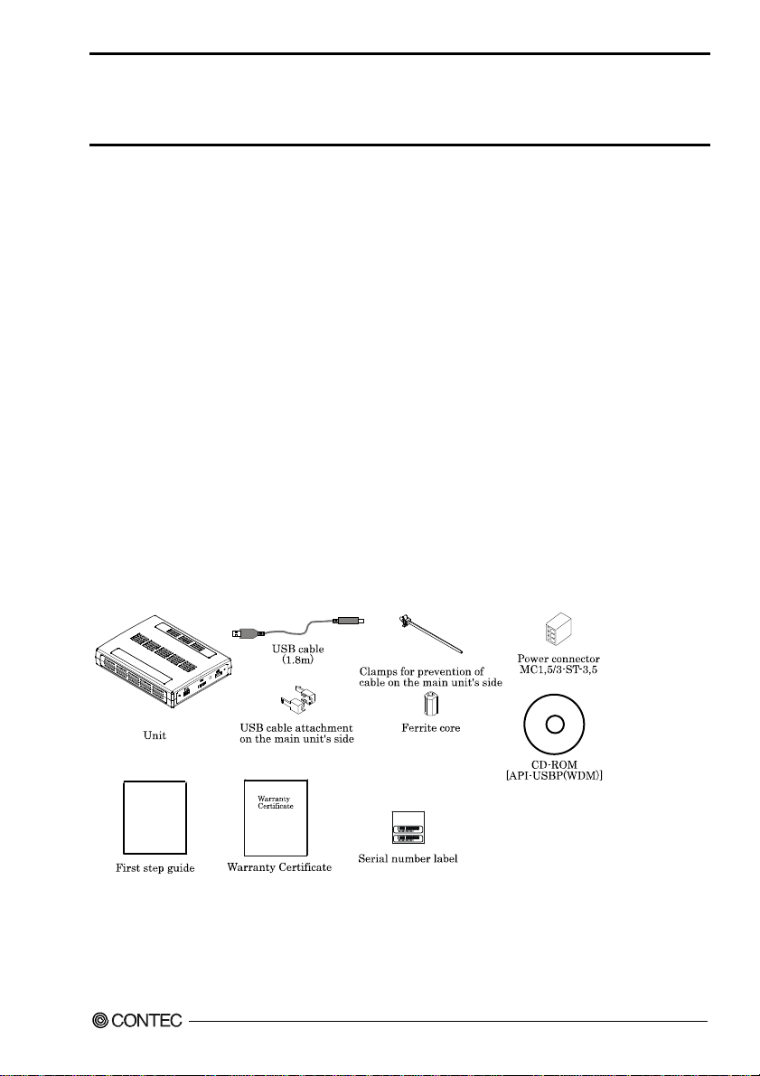
The product consists of the items listed below.
Check, with the following list, that your package is complete. If you discover damaged or missing
items, contact your retailer.
Product Configuration List
- Unit [DIO-3232LX-USB] …1
- USB cable (1.8m) …1
- USB cable attachment on the main unit’s side (For Mini B connector side) …1
- Clamps for prevention of cable on the main unit’s side …1
- CD-ROM *1 [API-USBP(WDM)] …1
- Power connector MC1,5/3-ST-3,5 …1
- First step guide …1
- Ferrite core …1
- Warranty Certificate …1
- Serial number label …1
*1 The CD-ROM contains the driver software and User’s Guide (this guide)
DIO-3232LX-USB
i
Page 3

Copyright
Copyright 2009 CONTEC CO., LTD. ALL RIGHTS RESERVED.
No part of this document may be copied or reproduced in any form by any means without prior written
consent of CONTEC CO., LTD.
CONTEC CO., LTD. makes no commitment to update or keep current the information contained in this
document. The information in this document is subject to change without notice.
All relevant issues have been considered in the preparation of this document. Should you notice an
omission or any questionable item in this document, please feel free to notify CONTEC CO., LTD.
Regardless of the foregoing statement, CONTEC assumes no responsibility for any errors that may
appear in this document or for results obtained by the user as a result of using this product.
Trademarks
MS, Microsoft, Windows and Windows NT are trademarks of Microsoft Corporation. Other brand and
product names are trademarks of their respective holder. Table of Contents
DIO-3232LX-USB
ii
Page 4

Table of Contents
Check Your P ackage................................................................................................................................ i
Copyright .................................................................................................................................................ii
Trademarks ..............................................................................................................................................ii
Table of Contents ...................................................................................................................................iii
1. BEFORE USING THE PRODUCT 1
About the U nit.........................................................................................................................................1
Features............................................................................................................................................. 1
Support Software.............................................................................................................................. 3
Cable & Connector (Opt ion) ........................................................................................................3
Accessories (Option).....................................................................................................................4
Customer Su pport.................................................................................................................................... 5
Web Site ...........................................................................................................................................5
Limited On e-Year Warranty................................................................................................................... 5
How to Obta in Service............................................................................................................................ 5
Liability ...................................................................................................................................................5
Safety Precautions................................................................................................................................... 6
Safety Information ...........................................................................................................................6
Handling Precautions....................................................................................................................... 6
Environment..................................................................................................................................... 8
Inspection ......................................................................................................................................... 8
Storage.............................................................................................................................................. 8
Disposal ............................................................................................................................................8
2. SETUP 9
What is Setup?......................................................................................................................................... 9
Installing the driver ..........................................................................................................................9
Step 1 Sett ing the Hardw are .................................................................................................................10
Name of each parts ......................................................................................................................... 10
Step 2 Initi alizing the Software ............................................................................................................11
Illustrati o n of Menu Sc r een...........................................................................................................11
Installati on of API-US BP(WDM) Development Environment....................................................12
Step 3 Installing the Hardware .............................................................................................................13
Connection w ith 5VDC Pow er Supply for S elf-power ................................................................13
Connecting the Product..................................................................................................................14
Setting wi th the Found New Hardware Wizard............................................................................ 16
Setting Properties Us ing Device Ma nager ....................................................................................17
Step 4 Checking Operations with the Diagno sis Progra m...................................................................19
What is the D iagnosis Pr o gram? ...................................................................................................19
DIO-3232LX-USB
iii
Page 5

Using the Di agnosis Program ........................................................................................................19
3. EXTERNAL CONNECTION 23
Using the Co nnectors.............................................................................................................................23
Connecting to a Connect or.............................................................................................................23
Connector Pin Assignment.............................................................................................................24
Relationships between L o gical Ports / Bits and Conn ector Signal Pins ........................................28
Connecting I n put Signals ......................................................................................................................29
Input Circuit....................................................................................................................................29
Connecting a Switch.......................................................................................................................29
Connecting Outp ut Signals....................................................................................................................30
Output Circuit.................................................................................................................................30
Connection to the LED...................................................................................................................31
Example of Connectio n to TTL Level Input .................................................................................31
Connecting t he Sink Type Output and Si n k Output Support Input .....................................................32
4. APPLICATION DEVELOPMENT 33
Reference to Online Help ......................................................................................................................33
Printing Fu nction Reference..................................................................................................................33
Sample Program.....................................................................................................................................34
Distributi n g Developed Applicati o n .....................................................................................................34
Returning to Initial State .......................................................................................................................35
5. FUNCTION 37
Data I/O Function ..................................................................................................................................37
Data Input .......................................................................................................................................37
Data Output.....................................................................................................................................37
Monitoring Output Dat a .................................................................................................................37
Digital Filter...........................................................................................................................................38
Digital Filter Function Principle ....................................................................................................38
Set Digital Filter Time....................................................................................................................38
Interrupt Control Func tion ....................................................................................................................39
Disabling/enabling In terrupts.........................................................................................................39
Selecting the Interrup t Edge ...........................................................................................................39
Clearing th e Interrupt S t atus and Int errupt Signal ........................................................................39
6. ABOUT HARDWARE 41
Hardware sp e cification..........................................................................................................................41
Physical dimensions ..............................................................................................................................43
Block Diagr am.......................................................................................................................................43
DIO-3232LX-USB
iv
Page 6
1. Before Using the Product
1. Before Using the Product
This chapter provides information you should know before using the product.
About the Unit
This product is an USB2.0-compliant digital I/O unit used to provide a digital signal I/O function on a
PC.
This product can input and output digital signals at 12 - 24VDC. This product features 32 channels of
Optocoupler isolated inputs (compatible with current sink output) and 32 channels of Op to coup ler
isolated open-collector outputs (current sink type). You can use 32 input signals as interrupt inputs.
Equipped with the digital filter function to prevent wrong recognition of input signals and output
transistor protection circuit (surge voltage protection and over current protection).
As there is compatible with PCI bus-compatible board PIO-32/32L(PCI)H and PCI Express
bus-compatible board DIO-3232L-PE in terms of connector shape and pin assignments, it is easy to
migrate from the existing system.
Windows driver is bundled with this product. Possible to be used as a data recording device for
LabVIEW, with dedicated libraries.
Features
- 32 channels of Optocoupler isolated inputs (compatible with current sink output) and 32 channels of
Optocoupler isolated open-collector outputs (current sink type)
This product has the 32 channels of Optocoupler isolated inputs (compatible with current sink output)
and the 32 channels of Optocoupler isolated open-collector outputs (current sink type) whose response
speed is 200µsec. Supporting driver voltages of 12 - 24 VDC for I/O.
(12 - 24VDC external circuit power supply is required separately.)
- Compatible to USB1.1/USB2.0
Compatible to USB1.1/USB2.0 and capable to achieve high speed transfer at HighSpeed (480 Mbps).
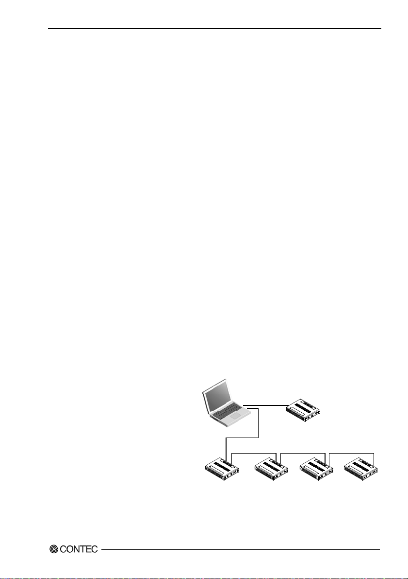
- USB HUB function
This product has the USB hub function.
Max. 4 DIO-3232LX-USB can be used in
1 USB port of PC. *1 When you use 4
or more DIO-3232LX-USB, you can do
by connecting DIO-3232LX-USB to the
another USB port of PC side. *2
Also, you can connect the CONTEC’s
USB device other than
DIO-3232LX-USB to the USB port of
DIO-3232LX-USB. *3*4
USB cable
USB cable USB cable USB cable
DIO-3232LX-USB
1
Page 7

1. Before Using the Product
- Common terminal provided per 16 channels
Common terminal provided per 16 channels, capable of supporting a different external power supply.
- Optocoupler bus isolation
As the USB (PC) is isolated from the input and output interfaces by Optocouplers, this product has
excellent noise performance.
- You can use 32 input signals as interrupt request signals.
You can use 32 input signals as interrupt request signals and also disable or enable the interrupt in bit
units and select the edge of the input signals, at which to generate an interrupt.
- This product has a digital filter to prevent wrong recognition of input signals from carrying noise or
a chattering.
This product has a digital filter to prevent wrong recognition of input signals from carrying noise or a
chattering. All input terminals can be added a digital filter, and the setting can be performed by
software.
- Output circuits include zener diodes for surge voltage protection and poly-switches for overcurrent
protection.
Zener diodes are connected to the output circuits to protect against surge voltages. Similarly,
polyswitches are fitted to each group of 8channels outputs for over-current protection.
The output rating is max. 35VDC, 100mA per channel.
- Connectors are compatible with PCI/PCI Express bus-compatible board
As there is compatible with PIO-32/32L(PCI)H and DIO-3232L-PE in terms of connector shape and pin
assignments, it is easy to migrate from the existing system. If the system of this product is created by
the digital I/O driver API-DIO(98/PC), it is required to replace it with API-DIO(WDM).
- Windows compatible driver libraries are attached.
Using the attached digital I/O driver API-DIO(WDM) makes it possible to create applications of
Windows. In addition, a diagnostic program by which the operations of hardware can be checked is
provided.
- LabVIEW is supported by a plug-in of dedicated library VI-DAQ.
Using the dedicated library VI-DAQ makes it possible to make a LabVIEW application.
*1 This product cannot be stacked up for installation.
*2 When you use the USB port included on the DIO-3232LX-USB, use 5VDC power supply for self-power. For more details on the
connection with 5VDC power supply, refer to chapter2 - step3, “Connection with 5VDC Power Supply for Self-power”.
*3 Do not connect the device other than that of CONTEC’s USB to the USB port included on the DIO-3232LX-USB. Otherwise, this
may cause a failure or malfunction.
*4 When connecting multiple units with USB HUB function and set up them, do one at a time and complete setup for the previous unit
before starting to do the next unit.
DIO-3232LX-USB
2
Page 8

1. Before Using the Product
Support Software
You should use CONTEC support software according to your purpose and development environment.
Windows version of digital I/O driver
API-DIO(WDM)
[Stored on the bundled CD-ROM driver library API-USBP(WDM)]
It is the library software, and w hich supplies command of ha rdware produced by our company in the form of standard
Win32 API function(DLL). Using programming languages supporting Win32API functions, such as Visual Basic
and Visual C++ etc., you can develop high-speed application software with feature of hardware produced by our
company.
In addition, you can verify the operation of hardware using Diagnostic pro grams.
< Operating environment >
OS Windows 7, Server 2008, Vista, XP, Server 2003, 2000, Me, 98
Adaptation language Visual Basic, Visual C++, Visual C#, Delphi, C++ Builder
You can download the updated version from the CONTEC’s Web site
(http://www.contec.com/product/device/apiusbp/). For more details on the supported OS, applicable language and
new information, please visit the CONTEC’s Web site.
Data acquisition VI library for LabVIEW
(Available for downloading (free of charge) from
VI-DAQ
the CONTEC web site.)
This is a VI library to use in National Instruments LabVIEW.
VI-DAQ is created with a function form similar to that of LabVIEW's Data Acquisition VI, allowing you t o use
various devices without complicated settings.
See http://www.contec.com/vidaq/ for details and download of VI-DAQ.
Cable & Connector (Option)
Shield Cable with 96-Pin Half-Pitch Connectors at Both Ends : PCB96PS-0.5P (0.5m)
: PCB96PS-1.5P (1.5m)
: PCB96PS-3P (3m)
: PCB96PS-5P (5m)
Flat Cable with 96-Pin Half-Pitch Connectors at Both Ends : PCB96P-1.5 (1.5m)
: PCB96P-3 (3m)
: PCB96P-5 (5m)
Shield Cable with 96-Pin Half-Pitch Connectors at One End : PCA96PS-0.5P (0.5m)
: PCA96PS-1.5P (1.5m)
: PCA96PS-3P (3m)
: PCA96PS-5P (5m)
DIO-3232LX-USB
3
Page 9

1. Before Using the Product
Flat Cable with 96-Pin Half-Pitch Connectors at One End : PCA96P-1.5 (1.5m)
: PCA96P-3 (3m)
: PCA96P-5 (5m)
Distribution shield cable with 96-Pin Half-Pitch Connectors(96P→37P x 2)
: PCB96WS-1.5P (1.5m)
: PCB96WS-3P (3m)
: PCB96WS-5P (5m)
Half Pitch 96P Female Connector Set(5 Pieces) : CN5-H96F
Accessories (Option)
Screw Terminal Unit (M3 x 96P) : EPD-96A *1 *4
Screw Terminal Unit (M3.5 x 96P) : EPD-96 *1
Terminal Unit for Cables (M2.5 x 96P) : DTP-64(PC) *1
Signal Monitor / Output Accessory
for Digital I/O (64P) : CM-64 L *1
Screw Terminal Unit (M3 x 37P) : EPD-37A *2 *4
Screw Terminal Unit (M3.5 x 37P) : EPD-37 *2
General Purpose Terminal (M3 x 37P) : DTP-3C *2
Screw Terminal (M2.5 x 37P) : DTP-4C *2
Signal Monitor / Output Accessory
for Digital I/O (32P) : CM-32L *2
Connection Conversion Board (96-Pin→37-Pin x 2) : CCB-96 *3
AC adaptor (input : 90 - 264VAC, output : 5VDC 2.0A) : POA200-20-2
USB I/O Unit Bracket for X Series : BRK-USB-X
AC-DC power supply unit (input: 85 - 132VAC, output: 5VDC 3.0A) : POW-AC13GY
AC-DC power supply unit (input: 85 - 264VAC, output: 5VDC 2.0A) : POW-AD22GY
DC-DC power supply unit (input: 10 - 30VDC, output: 5VDC 3.0A) : POW-DD10GY
DC-DC power supply unit (input: 30 - 50VDC, output: 5VDC 3.0A) : POW-DD43GY
*1 A PCB96P or PCB96PS optional cable is required.
*2 A PCB96WS optional cable is required separately.
*3 Optional PCB96P, PCB96PS or cable for 37Pin D-SUB is required separately.
*4 “Spring-up” type terminal is used to prevent terminal screws from falling off.
* Check the CONTEC’s Web site for more information on these options.
DIO-3232LX-USB
4
Page 10

1. Before Using the Product
Customer Support
CONTEC provides the following support services for you to use CONTEC products more efficiently
and comfortably.
Web Site
Japanese http://www.contec.co.jp/
English http://www.contec.com/
Chinese http://www.contec.com.cn/
Latest product information
CONTEC provides up-to-date information on products.
CONTEC also provides product manuals and various technical documents in the PDF.
Free download
You can download updated driver software and differential files as well as sample programs available in
several languages.
Note! For product information
Contact your retailer if you have any technical question about a CONTEC product or need its price,
delivery time, or estimate information.
Limited One-Year Warranty
CONTEC products are warranted by CONTEC CO., LTD. to be free from defects in material and
workmanship for up to one year from the date of purchase by the original purchaser.
Repair will be free of charge only when this device is returned freight prepaid with a copy of the
original invoice and a Return Merchandise Authorization to the distributor or the CONTEC group office,
from which it was purchased.
This warranty is not applicable for scratches or normal wear, but only for the electronic circuitry and
original products. The warranty is not applicable if the device has been tampered with or damaged
through abuse, mistreatment, neglect, or unreasonable use, or if the original invoice is not included, in
which case repairs will be considered beyond the warranty policy.
How to Obtain Service
For replacement or repair, return the device freight prepaid, with a copy of the original invoice. Please
obtain a Return Merchandise Authorization number (RMA) from the CONTEC group office where you
purchased before returning any product.
* No product will be accepted by CONTEC group without the RMA number.
Liability
The obligation of the warrantor is solely to repair or replace the product. In no event will the
warrantor be liable for any incidental or consequential damages due to such defect or consequences that
arise from inexperienced usage, misuse, or malfunction of this device.
DIO-3232LX-USB
5
Page 11
1. Before Using the Product
Safety Precautions
Understand the following definitions and precautions to use the product safely.
Safety Information
This document provides safety information using the following symbols to prevent accidents resulting
in injury or death and the destruction of equipment and resources. Understand the meanings of these
labels to operate the equipment safely.
DANGER
WAR NI NG
CAUTION
Handling Precautions
DANGER
Do not use the product where it is exposed to flammable or corrosive gas. Doing so may result in
an explosion, fire, electric shock, or failure.
CAUTION
- Do not strike or bend this product.
Otherwise, this may malfunction, overheat, cause a failure or breakage.
- Do not touch this product's terminals (edge connector) with your hands.
Otherwise, this may malfunction, overheat, or cause a failure.
If the terminals are touched by someone's hands, clean the terminals with industrial alcohol.
- Do not close the ventilation hole(s) of this product by, for example, placing an object. This may
cause overheating, malfunction, and/or failure of the product.
- Do not touch the external connector when the power is on.
Otherwise this may malfunction, overheat, cause a failure due to static electricity.
- Make sure that your PC can supply ample power to all this product installed.
Insufficiently energized products could malfunction, overheat, or cause a failure.
- When you use the USB port included on the DIO-3232LX-USB, use 5VDC power supply for
self-power.
- Do not connect the device other than that of CONTEC’s USB to the USB port included on the
DIO-3232LX-USB. Otherwise, this may cause a failure or malfunction.
- When connecting multiple units with USB HUB function and set up them, do one at a time and
complete setup for the previous unit before starting to do the next unit.
- The specifications of this product are subject to change without notice for enhancement and quality
improvement.
Even when using this product continuously, be sure to read the manual and understand the contents.
- Do not modify this product. CONTEC will bear no responsibility for any problems, etc., resulting
from modifying this product.
DANGER indicates an imminently hazardous situation which, if not avoided, will
result in death or serious injury.
WARNING indicates a potentially hazardous situation which, if not avoided, could
result in death or serious injury.
CAUTION indicates a potentially hazardous situation which, if not avoided, may
result in minor or moderate injury or in property damage.
DIO-3232LX-USB
6
Page 12

1. Before Using the Product
- Regardless of the foregoing statements, CONTEC is not liable for any damages whatsoever
(including damages for loss of business profits) arising out of the use or inability to use this
CONTEC product or the information contained herein.
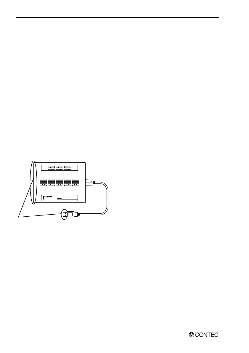
- If you use this product in a noisy environment, attach the bundled ferrite core to stabilize the
operation.
When attaching a ferrite core to the USB cable, coil it around once near the connector while leaving
it open, and then close it.
FCC PART 15 Class A Notice
NOTE
This device complies with Part 15 of the FCC Rules. Operation is subject to the following two conditions:
(1) this device may not cause harmful interference, and (2) this device must accept any interference received,
including interference that may cause undesired operation.
This equipment has been tested and found to comply with the limits for a Class A digital device, pursuant to Part 15
of the FCC Rules. These limits are designed to provide reasonable protection against harmful interference when the
equipment is operated in a commercial environment.
This equipment generates, uses, and can radiate radio frequency energy and, if not installed and used in accordance
with the instruction manual, may cause harmful interference to radio communications. Operation of this equipment in
a residential area is likely to cause harmful interference in which case the user will be requiredto correct the
interference at his own expense.
WARNING TO USER
Change or mo difications not expressly approved the manufacturer can void the user's authority to operate this
equipment.
DIO-3232LX-USB
7
Page 13
1. Before Using the Product
Environment
Use this product in the following environment. If used in an unauthorized environment, this product
may overheat, malfunction, or cause a failure.
Operating temperature
0 - 50°C
Humidity
10 - 90%RH (No condensation)
Corrosive gases
None
Floating dust particles
Not to be excessive
Inspection
Inspect the product periodically as follows to use it safely.
POWER
- Check that the connector has no dust or foreign matter adhering.
Storage
When storing this product, keep it in its original packing form.
(1) Put this product in the storage bag.
(2) Wrap it in the packing material, and then put it in the box.
(3) Store the package at room temperature at a place free from direct sunlight, moisture, shock,
vibration, magnetism, and static electricity.
Disposal
When disposing of the product, follow the disposal procedures stipulated under the relevant laws and
municipal ordinances.
DIO-3232LX-USB
8
Page 14

2. Setup
2. Setup
This chapter explains how to set up this product.
What is Setup?
Setup means a series of steps to take before the product can be used.
Different steps are required for software and hardware.
Installing the driver
This section enables you to prepare the software and hardware by operating in accordance with each
step in this chapter using the bundled CD-ROM. Taking the following steps sets up the software and
hardware. You can use the diagnosis program later to check whether the software and hardware
function normally.
Step 1 Setting the Hardware
Step 2 Installing the Software
Step 3 Installing the Hardware
Step 4 Checking Operations with the Diagnosis Program
Uninstall the driver and then set it up again if it cannot be set up properly.
DIO-3232LX-USB
9
Page 15

2. Setup
Step 1 Setting the Hardware
This section describes how to set up the product and how to connect it to a PC.
Name of each parts
LED indicator
Interface
connector (CN1)
The above figure has installed the USB cable attachment.
POWER Status
For PC
Interface connector
USB TypeA
Figure 2.1. Name of each parts (Front side)
USB cable
attachment
USB port
[Type A
connector]
USB port
[mini B
connector]
+5VDC input
terminal
DIO-3232LX-USB
10
Page 16

2. Setup
age
Step 2 Initializing the Software
Install software.
The following description assumes the operating system as Windows XP. Although some user
interfaces are different depending on the OS used, the basic procedure is the same.
Points
- If you are using Windows XP or Windows 2000, please log on as Administrator (authorized
account) before proceeding to the following steps.
The following shows the basic flow for installing product.
Initializing the Software
- Installation of
API-USBP(WDM)
Development Environment
P
11
Connecting the Product
- Connecting the PC
Illustration of Menu Screen
Page 14
Setting Properties Using
Device Manager
- Setting the Device
Name.
Page 16
Install Development Environment such as sample
programs and online help
Install utility.
Refer to the user’s guide.
Refer to the content of CD-ROM.
Install C-LOGGER.
* Cannot be used for this product.
Points
- Please set up the supplied CD-ROM if it has not been set up. The menu starts automatically.
- If the menu do not start, launch X:AUTORUN.EXE(X:CD-ROM drive) from [Run…] in Start
menu.
- The screen design may be different.
DIO-3232LX-USB
11
Page 17

2. Setup
Installation of API-USBP(WDM) Development Environment
Installation of development environment is namely installing supplied online help and sample program
in all language in order to use API function.
(1) Clicking on “Install Development or Execution Environment”.
[API-USBP(WDM) Installer] dialog box displays.
(2) Selecting “Advanced Digital I/O driver”.
(3) Clicking on “Continue” Button.
Please perform installation following the directions on the screen. And thus the installation is
completed.
* The screen design may be different.
DIO-3232LX-USB
12
Page 18

2. Setup
Step 3 Installing the Hardware
Under Windows, information about the converter needs to be detected by the OS. This is called
hardware installation.
To use more than one of this product, make sure to install them one by one, setting each unit after
completing the previous one.
Connection with 5VDC Power Supply for Self-power
When you use the HUB function (USB Type A connector) included on the DIO-1616LX-USB, this
product must be connected with 5VDC power supply (in a self-powered state). Connect with 5VDC
power supply by using +5VDC input pin.
Vi+ Power supply (5V)
Vi- Power supply (GND)
FG Frame ground
Figure 2.2. +5 VDC Input Terminal Pinouts
To supply power using the bundled power connector (MC1,5/3-ST-3,5, compatible cable
: AWG28 - 16), strip the end of the compatible cable, insert it into the power connector, then securely
screw it.
When using the optional AC adaptor [POA200-20-2], please co nnect directly to the input terminals.
POA200-20-2
Figure 2.3. Connecting the AC Adapter POA200-20-2
Beside the AC adaptor, a power supply for installation on a DIN rail is also available (as an option).
Use the appropriate power supply depending on the operating environment and application. When a
power supply for installation on a DIN rail is used, connect the unit using the accompanying power
connector MC1,5/-ST-3,5.
CAUTION
Connect 5VDC power supply to the main unit. Next, connect the USB cable to the PC. Do not
turn it on or off when using. If you remove, USB cable is first and then 5VDC power supply.
DIO-3232LX-USB
13
Page 19

2. Setup
Connecting the Product
(1) Turn on the power to the PC before connecting this product.
(2) When the PC has been up and running, plug the USB interface connector to a USB port in the PC.
The converter can also be connected to the PC via a USB hub of this product.
USB port
Figure 2.4. Connecting the PC
(3) USB cable can be attached firmly to the main unit by using a USB cable attachment.
mini B connector
Figure 2.5. Attaching a USB Attachment
CAUTION
- The USB cable attachment cannot be used excluding an attached cable.
- When the USB cable attachment is being used, do not perform removing and connecting the USB
cable on the unit side repeatedly. This may damage the USB cable attachment or yourself.
DIO-3232LX-USB
14
Page 20

2. Setup
(4) When connecting the USB cable through the USB hub of this product, it can be made easily not to
come off by using clamps for prevention of cable on the main unit's side (Appended goods).
Figure 2.6. Usage of clamps for prevention of cable on the main unit's side
DIO-3232LX-USB
15
Page 21

2. Setup
Setting with the Found New Hardware Wizard
(1) The “Found New Hardware Wizard” will be started.
* In Windows Vista, Because the driver's installation is completed by "Installing the Software", it is
not necessary to operate it about the Hardware Wizard.
(2) Select “Install from a list or specific location”, then click on the [Next] button.
Detect setup information from supplied CD automatically for installing USB driver.
* The name of the connected
product will be displayed.
DIO-3232LX-USB
Point
Please specify the path for supplied CD as follows in the case of failure in detecting automatically.
X:¥INF¥WDM¥DIO (X: CD-ROM drive)
(3) Click on [Finish] button to complete the installation of USB driver.
DIO-3232LX-USB
16
* The name of the connected
product will be displayed.
DIO-3232LX-USB
Page 22

2. Setup
Setting Properties Using Device Manager
After connecting product with a PC and completing driver installation, open Device Manager and set
properties.
(1) Starting Device Manager.
From [Start] menu, click on [Settings]-[Control Panel]-[System] and then click on [Device
Manager] button in [Hardware] tab.
* The name of the connected
product will be displayed.
DIO-3232LX-USB
- In the case of Windows 98/Me
Right-click on [My Computer] and select [Properties] to start device manager.
DIO-3232LX-USB
17
Page 23

2. Setup
(2) Setting th e Device Name.
Right-clicking on the product name and selecting [Properties] displays [Product Properties].
Open [Common Settings] tab and enter arbitrary name in the editing box for device name.
(Default name also can be used.)
* The name of the connected
product will be displayed.
DIO-3232LX-USB
* The product-specific number will be displayed as the serial number.
CAUTION
USB driver can not be used without settings. Settings must be performed.
(3) Clicking on [OK] button.
Device name is set by clicking [OK] button.
Points
- When the application developed by users is running on another PC, please perform foregoing
operation on the target computer. (No need to install software introduced on next page)
- Please use the device name specified in last step for initialization function when initialization is
performed using API function. When running on other PC, it can run without changing the
application for the same device name being specified.
DIO-3232LX-USB
18
Page 24

2. Setup
Step 4 Checking Operations with the Diagnosis Program
Use the diagnosis program to check that the product and driver software work normally, thereby you
can confirm that they have been set up correctly.
What is the Diagnosis Program?
The diagnosis program diagnoses the states of the product and driver software.
It can also be used as a simple checker when an external device is actually connected.
Using the “Diagnosis Report” feature reports the driver settings, the presence or absence of the product,
I/O status, and interrupt status.
Using the Diagnosis Program
Starting the Diagnosis Program
Click [Diagnosis] on the Properties page to start the diagnosis program.
* The name of the connected
product will be displayed.
DIO-3232LX-USB
DIO-3232LX-USB
19
Page 25

2. Setup
Checking Digital Inputs and Outputs
The main panel of the Diagnosis Program appears.
You can check the current operation states of the product in the following boxes:
“Input Port” : Displays input values bit by bit at fixed time intervals.
“Output Port” : Mouse operation allows the data to output or display.
* The name of the connected
product will be displayed.
DIO-3232LX-USB
Input port : 32Bit
Output port : 32Bit
will be displayed.
To use the function execution time measurement feature, click on the [Measurement Time] button.
Enter the I/O start port and the number of ports, then press the measurement button. The time for each
execution of a function will be measured.
DIO-3232LX-USB
20
Page 26

2. Setup
Diagnosis Report
(1) Clicking on the [Show Diagnosis Report] button displays detailed data such as product settings and
the diagnosis results while saving them in text format.
The Diagnosis Program performs “product presence/absence check”, “driver file test”, “board
setting test”, and so on.
CAUTION
Before executing diagnosis report output, unplug the cable from the product.
* The name of the connected
product will be displayed.
DIO-3232LX-USB
Input port : 32Bit
Output port : 32Bit
will be displayed.
(2) A diagnosis report is displayed as shown below.
* The name of the connected
product will be displayed.
DIO-3232LX-USB
DIO-3232LX-USB
Click on [Show
Diagnosis Report].
21
Page 27

2. Setup
DIO-3232LX-USB
22
Page 28

3. External Connection
3. External Connection
This chapter describes the interface connectors on the product and the external I/O circuits.
Check the information available here when connecting an external device.
Using the Connectors
Connecting to a Connector
To connect an external device to this product, plug the cable from the device into the interface
connector (CN1) of unit shown below.
- Connector used
PCR-E96LMD+ equivalence to it
[mfd. by HONDA TSUSHIN KOGYO CO., LTD.]
- Compatible connectors
Interface connector (CN1)
* Please refer to chapter 1 for more information on the supported cable and accessories.
Figure 3.1. Interface Connector Shape
PCR-E96FA+ equivalence to it
[mfd. by HONDA TSUSHIN KOGYO CO., LTD.]
DIO-3232LX-USB
23
Page 29

3. External Connection
Connector Pin Assignment
Pin Assignments of Interface Connector (CN1)
A48
[1]
[49]
B48
Pin No.
B47 OP 6/7
B46 O-77 A46 I-37
B45 O-76 A45 I-36
B44 O-75 A44 I-35
B43 O-74 A43 I-34
B42 O-73 A42 I-33
B41 O-72 A41 I-32
B40 O-71 A40 I-31
B39 O-70
B38 O-67 A38 I-27
B37 O-66 A37 I-26
B36 O-65 A36 I-25
B35 O-64 A35 I-24
B34 O-63 A34 I-23
B33 O-62 A33 I-22
B32 O-61 A32 I-21
B31 O-60
B30 ON 6/7 A30 N.C.
B29 ON 6/7
B28 N.C. A28 N.C.
B27 N.C. A27 N.C.
B26 N.C. A26 N.C.
B25 N.C. A25 N.C.
B24 N.C. A24 N.C.
B23 N.C. A23 N.C.
B22 N.C. A22 N.C.
B21 N.C.
B20 OP 4/5 A20 IP 0 /1
B19 OP 4/5
B18 O-57 A18 I-17
B17 O-56 A17 I-16
B16 O-55 A16 I-15
B15 O-54 A15 I-14
B14 O-53 A14 I-13
B13 O-52 A13 I-12
B12 O-51 A12 I-11
B11 O-50
B10 O-47 A10 I-07
B09 O-46 A09 I-06
B08 O-45 A08 I-05
B07 O-44 A07 I-04
B06 O-43 A06 I-03
B05 O-42 A05 I-02
B04 O-41 A04 I-01
B03 O-40
B02 ON 4/5 A02 N.C.
B01 ON 4/5
Signal
name
Meaning Pin No.
Common plus pin for
+6/+7 output ports
+7 port (output)
+6 port (output)
Common minus pin for
+6/+7 output ports
N.C.
Common plus pin for
+4/+5 output ports
+5 port (output)
+4 port (output)
Common minus pin for
+4/+5 output ports
* I-00 - I-37 can be used as interrupt input signal.
* [ ] shows pin numbers specified by HONDA TSUSHIN KOGYO CO., LTD.
CN1
A47 IP 2/3
A39 I-30
A31 I-20
A29 N.C.
A21 N.C.
A19 IP 0/1
A11 I-10
A03 I-00
A01 N.C.
Signal
name
A01
B01
[48]
[96]
Meaning
Common plus pin for
+2/+3 input ports
+3 port (input)
+2 port (input)
N.C.
Common plus pin for
+0/+1 input ports
+1 port (input)
+0 port (input)
N.C.
DIO-3232LX-USB
24
Page 30

3. External Connection
I-00 - I-37 32 input signal pins. Connect output signals from the external device to these pins.
O-40 - O-77 32 output signal pins. Connect these pins to the input signal pins of the external device.
IP 0/1 - IP 2/3
OP 4/5 - OP 6/7
ON 4/5 - ON 6/7
IP 0/1 Connect the positive side of the external power supply.
IP 2/3 Connect the positive side of the external power supply.
OP 4/5 Connect the positive side of the external power supply.
OP 6/7 Connect the positive side of the external power supply.
ON 4/5 Connect the negative side of the external power supply.
ON 6/7 Connect the negative side of the external power supply.
N.C. This pin is left unconnected.
Connect the positive side of the external power supply.
These pins are common to 16 input signal pins.
Connect the positive side of the external power supply.
These pins are common to 16 output signal pins.
Connect the negative side of the external power supply.
These pins are common to 16 output signal pins.
These pins are common to 16 pins of input sign I-00 - I-07, I-10 - I-17.
These pins are common to 16 pins of input sign I-20 - I-27, I-30 - I-37.
These pins are common to 16 pins of output sign O-40 - 0-47, O-50 - O-57.
These pins are common to 16 pins of output sign O-60 - 0-67, O-70 - O-77.
These pins are common to 16 pins of output sign O-40 - 0-47, O-50 - O-57.
These pins are common to 16 pins of output sign O-60 - 0-67, O-70 - O-77.
Figure 3.2. Pin Assignments of Interface Connector (CN1)
DIO-3232LX-USB
25
Page 31

3. External Connection
Pin Assignments of Optional Connector PCB96WS
- Optional cable PCB96WS
A
B
CNA CNB
N.C. 20 1 N.C.
I-20 21 2 I-00 O-60 21 2 O-40
I-21 22 3 I-01 O-61 22 3 O-41
I-22 23 4 I-02 O-62 23 4 O-42
I-23 24 5 I-03 O-63 24 5 O-43
+2 port
(Input)
I-24 25 6 I-04 O-64 25 6 O-44
I-25 26 7 I-05 O-65 26 7 O-45
I-26 27 8 I-06 O-66 27 8 O-46
I-27 28 9 I-07
I-30 29 10 I-10 O-70 29 10 O-50
I-31 30 11 I-11 O-71 30 11 O-51
I-32 31 12 I-12 O-72 31 12 O-52
I-33 32 13 I-13 O-73 32 13 O-53
+3 port
(Input)
I-34 33 14 I-14 O-74 33 14 O-54
I-35 34 15 I-15 O-75 34 15 O-55
I-36 35 16 I-16 O-76 35 16 O-56
I-37 36 17 I-17
Common
plus pin for
IP 2/3 37 18 IP 0/1
+2/+3 input
ports
19 N.C.
+0 port
(Input)
+1 port
(Input)
Common
plus pin for
+0/+1 input
ports
minus pin
(Output)
plus pin for
Common
for +6/+7
ON 6/7 20 1 ON 4/5
output
ports
+6 port
(Output)
O-67 28 9 O-47
+7 port
O-77 36 17 O-57
Common
+6/+7
OP 6/7 37 18 OP 4/5
output
ports
Figure 3.3. PCB96WS Signal Assignments
19 N.C.
Common
minus pin
for +4/+5
output
ports
+4 port
(Output)
+5 port
(Output)
Common
plus pin for
+4/+5
output
ports
DIO-3232LX-USB
26
Page 32

3. External Connection
Pin Assignments of Optional Connector CCB-96
- "Optional cable PCB96PS"
+ "Connector conversion board CCB-96"
Connector DCLC-J37SAF-20L9
or equivalence to it (mfd by JAE)
CCB-96
CN3(CNA)
N.C. 1 20 N.C.
I-00 2 21 I-20 O-40 2 21 O-60
I-01 3 22 I-21 O-41 3 22 O-61
I-02 4 23 I-22 O-42 4 23 O-62
I-03 5 24 I-23 O-43 5 24 O-63
+0 port
(Input)
I-04 6 25 I-24 O-44 6 25 O-64
I-05 7 26 I-25 O-45 7 26 O-65
I-06 8 27 I-26 O-46 8 27 O-66
I-07 9 28 I-27
I-10 10 29 I-30 O-50 10 29 O-70
I-11 11 30 I-31 O-51 11 30 O-71
I-12 12 31 I-32 O-52 12 31 O-72
I-13 13 32 I-33 O-53 13 32 O-73
+1 port
(Input)
I-14 14 33 I-34 O-54 14 33 O-74
I-15 15 34 I-35 O-55 15 34 O-75
I-16 16 35 I-36 O-56 16 35 O-76
Common plus
pin for +0/+1
I-17 17 36 I-37
IP 0/1 18 37 IP 2/3
input ports
N.C. 19
Common plus
pin for +2/+3
input ports
N.C. 19
Figure 3.4. CCB-96 Signal Assignments
+2 port
(Input)
+3 port
(Input)
minus pin for
+4/+5 output
Common plus
pin for +4/+5
output ports
Common
ON 4/5 1 20 ON 6/7
ports
+4 port
(Output)
O-47 9 28 O-67
+5 port
(Output)
O-57 17 36 O-77
OP 4/5 18 37 OP 6/7
CN4(CNB)
Common
minus pin for
+6/+7 output
ports
+6 port
(Output)
+7 port
(Output)
Common plus
pin for +6/+7
output ports
DIO-3232LX-USB
27
Page 33

3. External Connection
Relationships between Logical Ports/Bits and Connector Signal Pins
The following table lists the relationships between the connector signal pins and the logical port / bit
numbers.
Table 3.1. Logical Ports, Logical Bits, and Connector Signal Pins
D7 D6 D5 D4 D3 D2 D1 D0
I-07
I-06
I-05
I-04
I-03
I-02
I-01
Input logical port 0
Input logical port 1
Input logical port 2
Input logical port 3
D7 D6 D5 D4 D3 D2 D1 D0
Output logical port 0
Output logical port 1
Output logical port 2
Output logical port 3
Notes :
CAUTION
[7]
I-17
[15]
I-27
[23]
I-37
[31]
O-47
[7]
O-57
[15]
O-67
[23]
O-77
[31]
I-xx represents the input signal. O-xx represents the output signal.
[xx] represents the logical bit.
[6]
I-16
[14]
I-26
[22]
I-36
[30]
O-46
[6]
O-56
[14]
O-66
[22]
O-76
[30]
[5]
I-15
[13]
I-25
[21]
I-35
[29]
O-45
[5]
O-55
[13]
O-65
[21]
O-75
[29]
[4]
[3]
[2]
I-14
I-13
[11]
I-23
[19]
I-33
[27]
O-43
[3]
O-53
[11]
O-63
[19]
O-73
[27]
I-12
[10]
I-22
[18]
I-32
[26]
O-42
[2]
O-52
[10]
O-62
[18]
O-72
[26]
O -71
[12]
I-24
[20]
I-34
[28]
O-44
[4]
O-54
[12]
O-64
[20]
O-74
[28]
The logical port and logical bit numbers are virtual port and bit numbers that enable programming
independent of unit I/O addresses or unit types.
[1]
I-11
[9]
I-21
[17]
I-31
[25]
O-41
[1]
O-51
[9]
O-61
[17]
[25]
I-00
[0]
I-10
[8]
I-20
[16]
I-30
[24]
O-40
[0]
O-50
[8]
O-60
[16]
O-70
[24]
DIO-3232LX-USB
28
Page 34

3. External Connection
Connecting Input Signals
Connect the input signals to a device which can be current-driven, such as a switch or transistor output
device.
The connection requires an external power supply to feed currents.
This product inputs the ON/OFF state of the current-driven device as a digital value.
Input Circuit
Switch
External device Unit
External power
supply
12 - 24VDC
Vcc
Optocoupler
Vcc
Optocoupler
Unconnected
Unconnected
Plus
common
Input pin
Input pin Switch
* I-xx represents the input pin.
Figure 3.5. Input Circuit
The input circuits of interface blocks of this product is illustrated in Figure 3.5.
The signal inputs are isolated by Optocouplers (compatible with current sink output). This product
therefore requires an external power supply to drive the inputs. The power requirement for each input
pin is about 5.1mA at 24VDC (about 2.6mA at 12VDC).
Connecting a Switch
Input plus common (CN1 : A19pin)
I-00 (CN1 : A03pin)
Unit side
When the switch is ON, the corresponding bit contains 1.
When the switch is OFF, by contrast, the bit contains 0.
Figure 3.6. An Example to use Input I-00
Switch
+
External
power supply
12 - 24VDC
-
DIO-3232LX-USB
29
Page 35

3. External Connection
Connecting Output Signals
Connect the output signals to a current-driven controlled device such as a relay or LED.
The connection requires an external power supply to feed currents.
This product controls turning on/off the current-driven controlled device using a digital value.
Output Circuit
Vcc
Optocoupler
Optocoupler
Unit
Zener
diode
Zener
diode
PolySwitch
Plus
common
Output pin
Output pin
Minus
common
External device
*
Load
*
Load
External power
supply
12 - 24VDC
* O-xx represents the output pin.
Figure 3.7. Output Circuit
The output circuits of interface blocks of this product is illustrated in Figure 3.7.
The signal output section is an Optocoupler isolated, open-collector output (current sink type).
Driving the output section requires an external power supply.
The rated output current per channel is 100mA at maximum.
The output section can also be connected to a TTL level input as it uses a low-saturated transistor for
output. The residual voltage (low-level voltage) between the collector and emitter with the output on
is 0.5V or less at an output current within 50mA or at most 1.0V at an output current within 100mA.
A zener diode is connected to the output transistor for protection from surge voltages. A
PolySwitch-based overcurrent protector is provided for every 8 output transistors. When the
overcurrent protector works, the output section of this product is temporarily disabled. If this is the
case, turn of the power to the PC and the external power supply and wait for a few minutes, then turn
them on back.
CAUTION
When the PC is turned on, all output are reset to OFF.
DIO-3232LX-USB
30
Page 36

3. External Connection
Connection to the LED
Output plus common (CN1 : B19pin)
5.1k
Ω
Unit side
O-40 (CN1 : B03pin)
Output minus common (CN1 : B01pin)
When "1" is output to a relevant bit, the corresponding LED comes on.
When "0" is output to the bit, in contrast, the LED goes out.
LED
+
External
power supply
12 - 24VDC
-
Figure 3.8. An Example to use Output O-20
Example of Connection to TTL Level Input
External
power supply
12 - 24VDC
- +
Input unit
Output plus common
Output
2k
Vcc
Ω
TTL level input
Output minus common
GND
Figure 3.9. Connection Example of Output and TTL level Input Signal
DIO-3232LX-USB
31
Page 37

3. External Connection
Connecting the Sink Type Output and Sink Output Support Input
The following example shows a connection between a sink type output (output side) and a sink output
support input (input side). Refer to this connection example when you connect such this product to
each other.
External
power supply
12 - 24VDC
- +
Output unit
Output plus common
Output (sink type)
Output minus common
Input unit
Input plus common
Input (Compatible with sink output)
Figure 3.10. Example of Connecting the Sink Type Output and Sink Output Support Input
DIO-3232LX-USB
32
Page 38

4. Application Development
4. Application Development
Please reference to online help and sample program when developing applications.
Reference to Online Help
Click on [Programs]-[CONTEC API-USBP(WDM)]-[API-USBP(WDM) Help] from [Start] menu.
The information for application development, such as function reference is provided in
[API-USBP(WDM) Help].
Detailed introduction to search method for help should be found from [How to navigate Help] in the
help.
Printing Function Reference
Clicking on Print button from
online help prints the page being
displayed. It can be printed
entirely as follows in the case of
referencing to printing function.
As figure shown on the right,
selecting
on Print button prints all the
topics under the mark selected at
a time.
mark and clicking
DIO-3232LX-USB
33
Page 39

4. Application Development
Sample Program
To run a sample program, click on
[Programs] - [CONTEC
API-USBP(WDM)] -[DIO] [Sample Name] from [Start] menu.
Distributing Developed Application
Please distribute the developed application with USB driver in supplied CD-ROM.
Created application (including driver) can be freely distributed.
DIO-3232LX-USB
34
Page 40

4. Application Development
Returning to Initial State
This is the method of returning to initial state. It is suggested that you should return to initial state and
perform installation again when the operation is losing stabilization.
(1) Deleting Device form Device Manager.
* The name of the connected
product will be displayed.
DIO-3232LX-USB
(2) Drawing USB cable from a PC
USB port
(3) Uninstalling Driver
Select [CONTEC API-DIO(WDM) driver] from [My Computer]-[Control Panel]-[Add/Remove
Programs].
(4) Restarting
*1 If 5VDC power supply is used, unplug it too.
(It may not be normally initialized in the state of 5VDC power supply connection.)
DIO-3232LX-USB
35
Page 41

4. Application Development
DIO-3232LX-USB
36
Page 42

5. Function
5. Function
This section describes the features of this product.
Data I/O Function
Data Input
When input data is “ON”, “1” is input to the relevant bit.
When the input data is “OFF”, in contrast, “0” is input to the relevant bit
Data Output
When “1” is output to the relevant bit, the corresponding transistor is set to “ON”.
When “0” is output to the relevant bit, in contrast, the corresponding transistor is set to “OFF”.
CAUTION
When the PC is turned on, all output are reset to 0 (OFF).
Monitoring Output Data
This product can read the state of the data currently being output without affecting the output data.
DIO-3232LX-USB
37
Page 43

5. Function
Digital Filter
Using this feature, this product can apply a digital filter to every input pin, thereby preventing wrong
recognition of input signals from being affected by noise or chattering.
Digital Filter Function Principle
The digital filter checks the input signal level during the sampling ti me of the clock signal. When the
signal level remains the same for the digital filter set time, the digital filter recognizes that signal as the
input signal and changes the signal level of the PC
If the signal level changes at a frequency shorter than the set time, therefore, the level change is ignored.
Input Signal
Digital
Filter
Filter Setting Time
Input to PC
Input Signal
Invalid
Input to PC
Valid
Figure 5.1. Digital Filter Function Principle
Set Digital Filter Time
Set the digital filter time to 0 - 20 (14h).
Setting the digital filter time to 0 disables digital filtering. It is set to 0 when the power is turned on.
Figure 5.2 shows the relationships between digital filter time settings and the actual digital filter times.
Digital Filter Time[sec.] = 2
n: = setting data(0 - 20)
Setting Data
(n)
0 (00h) The filter function
1 (01h) 0.25μsec 8 (08h) 32μsec 15 (0Fh) 4.096msec
2 (02h) 0.5μsec 9 (09h) 64μsec 16 (10h) 8.192msec
3 (03h) 1μsec 10 (0Ah) 128μsec 17 (11h) 16.384msec
4 (04h) 2μsec 11 (0Bh) 256μsec 18 (12h) 32.768msec
5 (05h) 4μsec 12 (0Ch) 512μsec 19 (13h) 65.536msec
6 (06h) 8μsec 13 (0Dh) 1.024msec 20 (14h) 131.072msec
Digital Filter
Time
is not used.
Figure 5.2. Digital Filter Time and Setting Data
CAUTION
- If you set the digital filter time, the filter applies to all input pins. You cannot apply the filter only
to a specific filter.
- Do not set Setting Data to a value outside the above range as doing so can cause this product to
malfunction.
DIO-3232LX-USB
38
n
/ (8 x 10⁶)
Setting Data
(n)
7 (07h) 16μsec 14 (0Eh) 2.048msec
Digital Filter
Time
Setting Data
(n)
Digital Filter
Time
Page 44

5. Function
Interrupt Control Function
This product can use all of the input signals as interrupt request signals.
This product can generate an interrupt request signal to the PC when the input signal change from High
to Low or from Low to High.
When the digital filter (described above) is used, interrupt requests are generated by input signals that
have passed through the filter.
Disabling/enabling Interrupts
Interrupt mask bits can be used to disable or enable the individual bits for interruptions.
Once a certain bit has been interrupt-disabled, no interrupt occurs even when the corresponding input
signal changes its level.
To let interrupts occur, enable the corresponding interrupt mask bit for interruptions.
CAUTION
All of the interrupt mask bits are interrupt-disabled when the power is turned on.
Selecting the Interrupt Edge
Interrupt edge select bits can be used to set the input logic for interruption bit by bit.
If you set an interrupt edge select bit to 0, an interrupt occurs when the input value to the corresponding
bit changes from 0 to 1 (at the fall of the input signal from High to Low).
If you set an interrupt edge select bit to 1, an interrupt occurs when the input value to the corresponding
bit changes from 1 to 0 (at the rise of the input signal from Low to High).
CAUTION
When the power is turned on, all of the interrupt edge select bits are set to 0 so that an interrupt
occurs when the input value changes from 0 to 1 (at the fall of the input signal from High to Low).
Clearing the Interrupt Status and Interrupt Signal
Interrupt status bits are used to identify the input signal bit being used for requesting an interrupt.
When an interrupt status is input, the interrupt request signal and the in terrupt status are cleared
automatically.
CAUTION
- All of the interrupt status bits are set to 0 when the power is turned on.
- If an interrupt mask bit has been set to disable interrupts, the interrupt status bit is not set even
when the input signal changes its level.
DIO-3232LX-USB
39
Page 45

5. Function
DIO-3232LX-USB
40
Page 46

6. About Hardware
6. About Hardware
Hardware specification
Table 6.1. Specification
Item Specification
Input section
Number of input signal channels
Input format
Input resistance
Input ON current 2.0mA or more
Input OFF current 0.16mA or less
Interrupt 32 interrupt input signals are arranged into a single output
Response time 200
Output section
Number of output signal channels
Output format
Output
rating
Residual voltage with output on
Surge protector
Response time
USB section
Bus specification USB Specification 2.0/1.1 standard
USB transfer rate 12Mbps (Full-speed), 480Mbps (High-speed) *3
Power supply Bus power / Self-power *4
Common section
Number of terminals used at the
same time
Dielectric strength
External circuit power supply*6
Current consumption (Max.)
Operating conditions*7*8
Allowable distance of signal
extension
Physical dimensions (mm)
Weight
Connector
Attached cable
Applicable wire AWG28 - 16
*1 Data “0” and “1” correspond to the High and Low levels, respectively.
*2 The Optocoupler's response time comes.
*3 This depends on the PC environment used (OS and USB host controller).
*4 Use 5VDC power supply for sefl-power when you use the USB hub function.
*5 As a USB hub is also counted as one device, you cannot just connect 127 USB unit.
Output voltage 35VDC (Max.)
Output current 100mA (per channel) (Max.)
DIO-3232LX-USB
32 channels (all available for interrupts) (1 common in 16 channels)
Optocoupler isolated input (Compatible with current sink output)
(Negative logic *1)
4.7kΩ
of interrupt request signal. An interrupt is generated at the rising edge
(HIGH-to-LOW transition) or falling edge (LOW-to-HIGH transition) (set
by software).
μsec within *2
32 channels (1 common)
Optocoupler isolated open collector output (current sink type)
(Negative logic*1)
0.5V or less (Output current
Zener diode RD47FM(NEC) or equivalent
200
μsec within *2
127 terminals (Max.) *5
1000Vrms
12 - 24VDC(±10%)
5VDC 400mA
0 - 50ºC, 10 - 90%RH (No condensation)
Approx. 50m (depending on wiring environment)
180(W) x 140(D) x 34(H) (No protrusions)
300g (Not including the USB cable, attachment)
96pin half-pitch connector [M(male)type]
PCR-E96LMD+ [mfd. by HONDA TSUSHIN KOGYO CO., LTD.] or
equivalence to it
USB cable 1.8m
≤50mA), 1.0V or less (Output current≤100mA)
41
Page 47

6. About Hardware
*6 External circuit power supply is required separately.
*7 To suppress the heating, ensure that there are spaces for ventilation (about 5cm) around this product.
*8 When using the attached AC adaptor POA200-20-2, it is 0 - 40℃
DIO-3232LX-USB
42
Page 48

6. About Hardware
Physical dimensions
Figure 6.1. Physical dimensions
Block Diagram
GND
D-
D+
VCC
USB Connector
Figure 6.2. Block Diagram
DIO-3232LX-USB
USB
Controll
&
CPU
Opto-coupler
&
Trans istor s
Optocoupler
Isolated line
Digital Output
Digital Input
I/O Connec tor
43
Page 49

DIO-3232LX-USB
User’s Guide
CONTEC CO., LTD. May 2012 Edition
3-9-31, Himesato, Nishiyodogawa-ku, Osaka 555-0025, Japan
Japanese http://www.contec.co.jp/
English http://www.contec.com/
Chinese http://www.contec.com.cn/
No part of this document may be copied or reproduced in any form by any means without prior written
consent of CONTEC CO., LTD. [05232012]
[01272009] Management No. A-51-644
[05232012_rev4] Parts No. LYKB444
 Loading...