

Page 1

PC-HELPER
Bi-Directional Digital I/O
Terminal for USB2.0
DIO-24DY-USB
User’s Guide
CONTEC CO.,LTD.
Page 2
Check Your Package
Thank you for purchasing the CONTEC product.
The product consists of the items listed below.
Check, with the following l ist, that yo ur package is c omplete. If y ou discover dam aged or m issing item s,
contact your retailer.
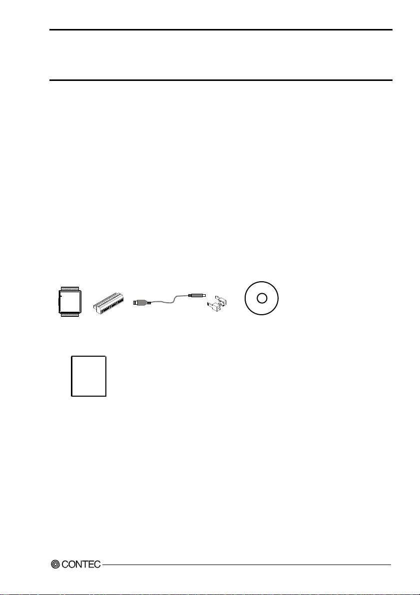
Product Configuration List
- USB terminal [DIO-24DY-USB]…1
- Interface connector plugs…2
- First step guide…1
- CD-ROM *1 [API-USBP(WDM)]…1
- USB Cable(1.8m)…1
- USB Cable Attachment…1
*1 The CD-ROM contains the driver software and User’s Guide (this guide)
USB terminal
connector plug
First step guide
DIO-24DY-USB
Interfac e
x 2
USB Cable
(1.8m)
USB Cable
Attachment
CD-ROM
[API-USBP(WDM)]
i
Page 3

Copyright
Copyright 2006 CONTEC CO., LTD. ALL RIGHTS RESERVED
No part of this document may be copied or reproduced in any form by any means without prior written
consent of CONTEC CO., LTD.
CONTEC CO., LTD. makes no commitment to update or keep current the information contained in this
document. The information in this document is subject to change without notice.
All relevant issues have been considered in the preparation of this document. Should you notice an
omission or any questionable item in this document, please feel free to notify CONTEC CO., LTD.
Regardless of the foregoing statement, CONTEC assumes no responsibility for any errors that may
appear in this document or for results obtained by the user as a result of using this product.
Trademarks
MS, Microsoft, Windows and Windows NT are trademarks of Microsoft Corporation. Other brand and
product names are trademarks of their respective holder.
DIO-24DY-USB
ii
Page 4

1. Before Using the Product
Table of Contents
Check Your Packag e............................................................................................................................i
Copyright ............................................................................................................................................ii
Trademarks ......................................................................................................................................... ii
Table of Con tents ..............................................................................................................................iii
1. BEFORE USING THE PRODUCT 1
About the Prod u ct............................................................................................................................... 1
Features........................................................................................................................................ 1
Support Soft wa re ......................................................................................................................... 2
Cable & Conne c to r ( Op t ion ) ...................................................................................................... 2
Accessories (Op t i on ) .................................................................................................................. 2
Customer Supp o rt ............................................................................................................................... 3
Web Site....................................................................................................................................... 3
Limited One- Yea r Wa rr an t y ............................................................................................................... 3
How to Obtain Se rv i c e ....................................................................................................................... 3
Liability .............................................................................................................................................. 3
Safety Precau ti o n s .............................................................................................................................. 4
Safety Infor mat i o n....................................................................................................................... 4
Handling Pre ca u tio ns................................................................................................................... 4
Environment ................................................................................................................................ 6
Inspection..................................................................................................................................... 6
Storage ......................................................................................................................................... 6
Disposal ....................................................................................................................................... 6
2. SETUP 7
What is Setup? .................................................................................................................................... 7
Installing the driver ..................................................................................................................... 7
Step 1 Setting th e H a rd wa r e............................................................................................................... 8
Name of each p ar t s ...................................................................................................................... 8
Step 2 Initial iz in g th e Sof t wa re.......................................................................................................... 9
Illustration of Menu Scre en ......................................................................................................... 9
Installation of AP I- U SB P( WD M) D ev e lopment Environmen t ................................................10
Step 3 Installi ng t h e H a rd wa re ......................................................................................................... 11
Connecting th e P r odu ct .............................................................................................................11
Setting with th e A dd Ne w H ard w a re Wi z ard............................................................................ 12
Setting Prop e rti es Us in g De vi ce M an ag e r ................................................................................ 13
Step 4 Checkin g Operations with th e Dia gn o sis P rog r a m............................................................... 15
What is the Diag n os is Pro g ram? ............................................................................................... 15
Using the Di agnosis Progra m.................................................................................................... 15
DIO-24DY-USB
iii
Page 5
3. EXTERNAL CONNECTION 19
Using the On-terminal Connectors...................................................................................................19
Connecting a termin a l t o a Connector....................................................................................... 19
Connector Pin As si gnment........................................................................................................ 20
Relationships bet w een Lo gi ca l Po rt s/ Bit s and Co n ne cto r S ign a l Pin s..................................... 20
Cable connect io n .......................................................................................................................21
Connecting I/ O Sig na l s.....................................................................................................................22
4. APPLICATION DEVELOPMENT 23
Reference to Onli ne H elp ................................................................................................................. 23
Printing Func ti on Ref e r en c e............................................................................................................. 23
Sample Progr a m ................................................................................................................................ 24
Distributing D ev e lop ed A pp li c a tio n ................................................................................................24
Returning to Initial State .................................................................................................................. 25
5. FUNCTIONS 29
I/O Function...................................................................................................................................... 29
6. ABOUT HARDWARE 31
Hardware spe cification..................................................................................................................... 31
Physical di mensions ......................................................................................................................... 32
Block Diagra m.................................................................................................................................. 32
DIO-24DY-USB
iv
Page 6

1. Before Using the Product
1. Before Using the Product
About the Product
This product is a USB2.0-compatible terminal that allows your PC to expand the bidirectional I/O
functionality of digital signals. The terminal comes with 24 channels of non-insulated LVTTL-level
inputs/outputs. Inputs and outputs can be switched in blocks of eight by software. Its compact
appearance makes it suitable for PC a pplicati on. In additi on, no e xternal p ower su pply is r equired , as the
terminal operates on the USB bus power.
Windows driver is bundled with this product.
Possible to be used as a data recording device for LabVIEW, with dedicated libraries.
Features
- Non-insulated LVTTL-level inputs/outputs (Positive)
The product is provided with 24 non-insulated LVTTL-level I/O ports with a response speed of 200 nsec
(positive logic). This allows you to use a total of up to 24 channels of I/O digital signals in three sets of
eight.
- Compatible to USB1.1/USB2.0 and not necessary to power t his prod uct exter nally as t he bus po wer is
used.
Compatible to USB1.1/USB2.0 and capable to achieve high speed transfer at HighSpeed (480 Mbps).
Not necessary to power this product externally as the bus power of USB is used.
- Easy-to-wire terminal connector adopted
Adoption of terminal connector (with screws) enables to achieve easy wiring.
- Windows compatible driver libraries are attached.
Using the attached driver library API-USBP(WDM) makes it possible to create appl ications of Windows.
In addition, a diagnostic program by which the operations of hardware can be checked is provided.
- LabVIEW is supported by a plug-in of dedicated library VI-DAQ.
Using the dedicated library VI-DAQ makes it possible to create each application for LabVIEW.
DIO-24DY-USB
1
Page 7

1. Before Using the Product
Support Software
You should use CONTEC support software accor d ing to your purpose and development environment.
Windows version of digital I/O driver
[Stored on the bundled CD-ROM driver library API-USBP(WDM)]
It is the library software, and which supplies command of hardware produced by our company in the
form of standard Win32 API function (DLL). Using programming languages supporting Win32API
functions, such as Visual Basic and Visual C++ etc., you can develop high-speed application software
with feature of hardware produced by our company.
In addition, you can verify the operation of hardware using Diagno stic progra ms.
< Operating Environment >
OS Windows 7, Vista, XP, Server 2003, 2000, Me, 98
Adaptation language Visual Basic, Visual C++, Visual C#, Delphi, C++ Builder
Data acquisition VI library for LabVIEW
the CONTEC web site.)
This is a VI library to use in National Instruments LabVIEW.
VI-DAQ is created with a function form similar to that of LabVIEW's Data Acquisition VI, allowi ng you
to use various devices without complicated settings.
See http://www.contec.com/vidaq/ for details and download of VI-DAQ.
API-DIO(WDM)
VI-DAQ
(Available for downloading (free of charge) from
Cable & Connector (Option)
14pin Screw Terminal Connector Set(6 pieces) : CN6-Y14
Accessories (Option)
Bracket for USB I/O Terminal products : BRK-USB-Y
* Check the CONTEC’s Web site for more information on these options.
DIO-24DY-USB
2
Page 8

1. Before Using the Product
Customer Support
CONTEC provides the following s upport services fo r you to use CONTEC products more efficiently and
comfortably.
Web Site
Japanese http://www.contec.co.jp/
English http://www.contec.com/
Chinese http://www.contec.com.cn/
Latest product information
CONTEC provides up-to-date information on products.
CONTEC also provides product manuals and various technical documents in the PDF.
Free download
You can download updated driver software a nd diff erenti al files as we ll as sample pr ograms available i n
several languages.
Note! For product information
Contact your retailer if you have any technical question about a CONTEC product or need its price,
delivery time, or estimate information.
Limited One-Year Warranty
CONTEC products are warranted by CONTEC CO., LTD. to be free from defects in material and
workmanship for up to one year from the date of purchase by the original purchaser.
Repair will be free of char ge only w hen thi s device is ret urned fr eight pr epaid with a c opy of t he origi nal
invoice and a Return Merchandise Authorization to the distributor or the CONTEC group office, from
which it was purchased.
This warranty is not applicable for scratches or normal wear, but only for the electronic circuitry and
original products. The warranty is not applicable if the device has been tampered with or damaged
through abuse, mistreatment, neglect, or unreasonable use, or if the original invoice is not included, in
which case repairs will be considered beyond the warranty policy.
How to Obtain Service
For replacement or repair, return the device freight prepaid, with a copy of the original invoice. Please
obtain a Return Merchandise Authorization Number (RMA) from the CONTEC group office where you
purchased before returning any product.
* No product will be accepted by CONTEC group without the RMA number.
Liability
The obligation of the warrantor is solely to repair or replace the product. In no event will the warrantor
be liable for any incidental or consequential damages due to s uch defec t or consequence s that arise from
inexperienced usage, misuse, or malfunction of this device.
DIO-24DY-USB
3
Page 9
1. Before Using the Product
Safety Precautions
Understand the following definitions and precautions to use the product safely.
Safety Information
This document provides safety information u sing the foll owing sym bols to prevent a ccidents res ulting in
injury or death and the destruc tion of equi pment and res ources. Under stand the mean ings of these la bels
to operate the equipment safely.
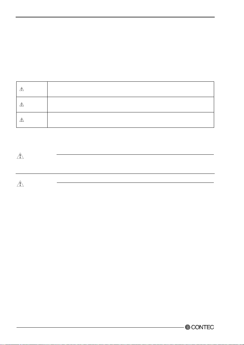
DANGER
WAR NI NG
CAUTION
DANGER indicates an imminently hazardous situation which, if not avoided, will
result in death or serious injury.
WARNING indicates a potentially hazardous situation which, if not avoided, could
result in death or serious injury.
CAUTION indicates a potentially hazardous situation which, if not avoided, may
result in minor or moderate injury or in property damage.
Handling Precautions
DANGER
Do not use the product wher e it is e xposed t o flam mable or corr osive ga s. Doi ng so m ay resu lt in a n
explosion, fire, electric shock, or failure.
CAUTION
- Do not strike or bend the converter.
Otherwise, the converter may malfunction, overheat, cause a failure or breakage.
- Do not touch the converter's pin parts (USB connector, GPIB connector) with your hands.
Otherwise, the converter may malfunction, overheat, or cause a failure.
If the pin parts are touched by someone's hands, clean the parts with industrial alcohol.
- Do not touch the external connector (14 pin plug header) when the power is on.
Otherwise this may malfunction, overheat, cause a failure due to static electricity.
- Make sure that your PC or expansion unit can supply ample power to all the products installed.
Insufficiently energized products could malfunction, overheat, or cause a failure.
- The specifications of this product are subject to change without notice for enhancement and quality
improvement.
Even when using the product continuously, be sure to read the manual and understand the contents.
- Do not modify the product. CONTEC will bear no responsibility for any problems, etc., resulting
from modifying this product.
- Regardless of the foregoing statements, CONTEC is not liable for any damages whatsoever
(including damages for loss of business profits) arising out of the use or inability to use this
CONTEC product or the information contained herein.
DIO-24DY-USB
4
Page 10

1. Before Using the Product
- It may cause a trouble in recognizing and operating the device according to the kind of USB hub. If
you use the USB hub, we encourage you to take advantage of the CONTEC’s product loan ser vice to
confirm operation before purchasing.
FCC PART 15Class A Notice
NOTE
This device complies with Part 15 of the FCC Rul es. Op eration is subj ect to the foll owi ng two c onditi ons : (1) this
device may not cause harmful interference, and (2) this device must accept any interference received, including
interference that may cause undesired operation.
This equipment has been tested and found to comply with the limits for a Class A digital device, pursuant to part 15
of the FCC Rules. These limits are designed to provide reasonable protection against harmful interference when the
equipment is operated in commercial environment.
This equipment generates, uses, and can radiate radio frequency energy and, if not installed and used in accordance
with the instruction manua l, may ca use harmf ul interfe rence to ra dio comm unicatio ns. Operati on of this equipmen t in
a residential area is likely to cause harmful interference at his own expense.
WARNING TO USER
Change or modifications not expressly approved the manufacturer can void the user's authority to operate this
equipment.
DIO-24DY-USB
5
Page 11
1. Before Using the Product
Environment
Use this product in the following environment. If used in an unauthorized environment, the converter
may overheat, malfunction, or cause a failure.
Operating temperature
0 - 50°C
Humidity
10 - 90%RH (No condensation)
Corrosive gases
None
Floating dust particles
Not to be excessive
Inspection
Inspect the product periodically as follows to use it safely.
- Check that the
connector has no
dust or foreign matter
adhering.
Storage
When storing this product, keep it in its o r iginal packing form.
(1) Put the product in the storage bag.
(2) Wrap it in the packing material, then put it in the box.
(3) Store the package at room temperature at a place free from direct sunlight, moisture, shock,
vibration, magnetism, and static electricity.
Disposal
When disposing of the product, follow the disposal procedures stipulated under the relevant laws and
municipal ordinances.
DIO-24DY-USB
6
Page 12

2. Setup
2. Setup
This chapter explains how to set up the product.
What is Setup?
Setup means a series of steps to take before the product can be used.
Different steps are required for software and hardware.
Installing the driver
This section enables you to prepare the software a nd hardware by operating in accordanc e with each s tep
in this chapter using the bundled CD-ROM. Taking the following steps sets up the software and
hardware. You can use the diagnosis program later to check whether the software and hardware function
normally.
Step 1 Setting the Hardware
Step 2 Installing the Software
Step 3 Installing the Hardware
Step 4 Checking Operations with the Diagnosis Program
Uninstall the driver and then set it up again if it cannot be set up properly.
DIO-24DY-USB
7
Page 13

2. Setup
Step 1 Setting the Hardware
This section describes how to set up the product and how to connect it to a PC.
Name of each parts
LED indicator
LINK Status
Interface connector
USB TypeA
Figure 2.1. Name of each parts (Front side)
Table 2.1. List of Status LED Functions
Name Function Indicator color LED indicator
ON : Communication established
OFF : Communication unestablished
ON : PC communication established
OFF : PC communication unestablished
LINK Status
USB communication status
GREEN
PC connection status
DIO-24DY-USB
8
Page 14

2. Setup
Step 2 Initializing the Software
Connect with the product, and install following software if USB driver has been installed.
The following description assumes the operating system as Windows XP. Although some user
interfaces are different depending on the OS used, the basic procedure is the same.
Points
- If you are using Windows XP or Windows 2000, please log on as Administrator (authorized
account) before proceeding to the following steps.
The following shows the basic flow for installing product.
Initializing the Software
- Installation of
API-USBP(WDM)
Development Environment
Connecting the Product
- Connecting the PC
Page 9 Page 11
Illustration of Menu Screen
Setting Properties Using
Device Manager
- Setting the Device Name.
Page 13
Install the Development Environment such
as sample programs and online help, etc.
Install the utility.
Refer to the user’s guide.
Refer to the description
about CD-ROM.
Install the C-LOGGER.
*Cannot be used for th is product.
Points
- Please set up the supplied CD-ROM if it has not been set up. The menu starts automatically.
- If the menu do not start, launch X:AUTORUN.EXE(X:CD-ROM drive) from [Run…] in Start
menu.
- The screen design may be different.
DIO-24DY-USB
9
Page 15
2. Setup
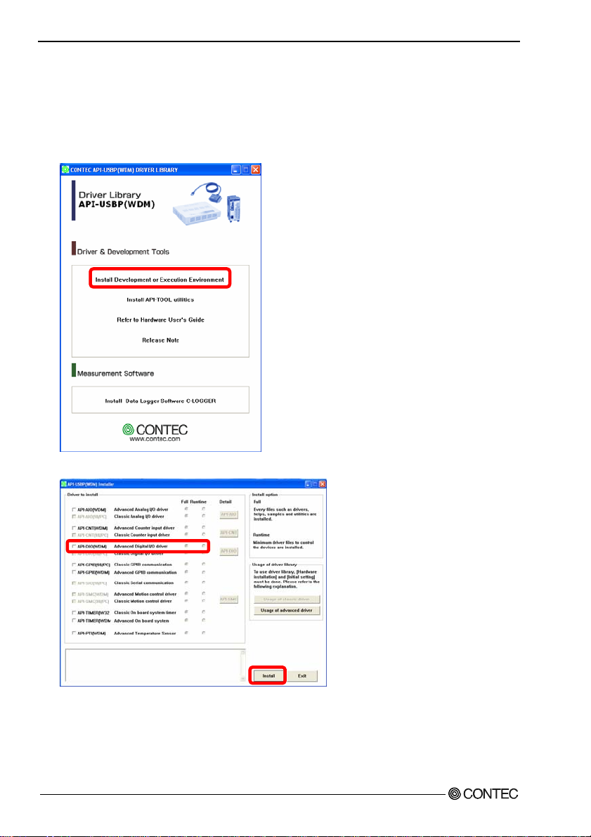
Installation of API-USBP(WDM) Development Environment
Installation of development environment is namely installing supplied online help and sample program
in all language in order to use API function.
(1) Clicking on “Install Development or Execution Environment”.
[API-USBP(WDM) Installer] dialog box displays.
(2) Selecting “Advanced Digital I/O driver”.
(3) Clicking on “Install” Button.
Please perform installation following the directions on the screen. And thus the installation is
completed.
* The screen design may be different.
DIO-24DY-USB
10
Page 16

2. Setup
Step 3 Installing the Hardware
Under Windows, information about the converter needs to be detected by the OS. This is called
hardware installation .
To use more than one of this product, make sure to install them one by one, setting each unit after
completing the previous one.
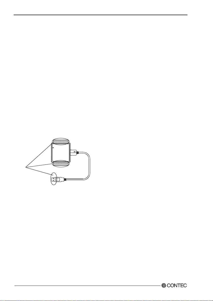
Connecting the Product
(1) Turn on the power to the PC before connecting the product.
(2) When the PC has been up and running, plug the USB interface connector to a USB port in the PC.
The converter can also be connected to the PC via a USB hub.
Figure 2.2. Connecting the PC
CAUTION
It may cause a trouble in recognizing and operating the device according to the kind of USB hub. If
you use the USB hub, we encourage you to take advantage of the CONTEC’s product loan ser vice to
confirm operation before purchasing.
(3) USB cable can be attached firmly to the main unit by using a USB cable attachment.
Figure 2.3. Attaching a USB Attachment
CAUTION
The USB cable attachment cannot be used excluding an attached cable.
DIO-24DY-USB
USB port
11
Page 17

2. Setup
Setting with the Add New Hardware Wiza r d
(1) The “Found New Hardware Wizard” will be started.
In Windows Vista, Because the driver's installation is completed by "Installing the Software",it is
not necessary to operate it about the Hardware Wizard.
(2) Select “Install from a list or specific location”, then click on the [Next] button.
Detect setup information from supplied CD automatically for installing USB driver.
* The name of the connected
product will be displayed.
- DIO-24DY-USB
Point
Please specify the path for supplied CD as follows in the case of failure in detecting automatically.
X:\INF\WDM\DIO (X: CD-ROM drive)
(3) Click on [Finish] button to complete the installation of USB driver.
DIO-24DY-USB
12
* The name of the connected
product will be displayed.
- DIO-24DY-USB
Page 18
2. Setup
Setting Properties Using Device Manager
After connecting product with a PC and completing driver installation, open Device Manager and set
properties.
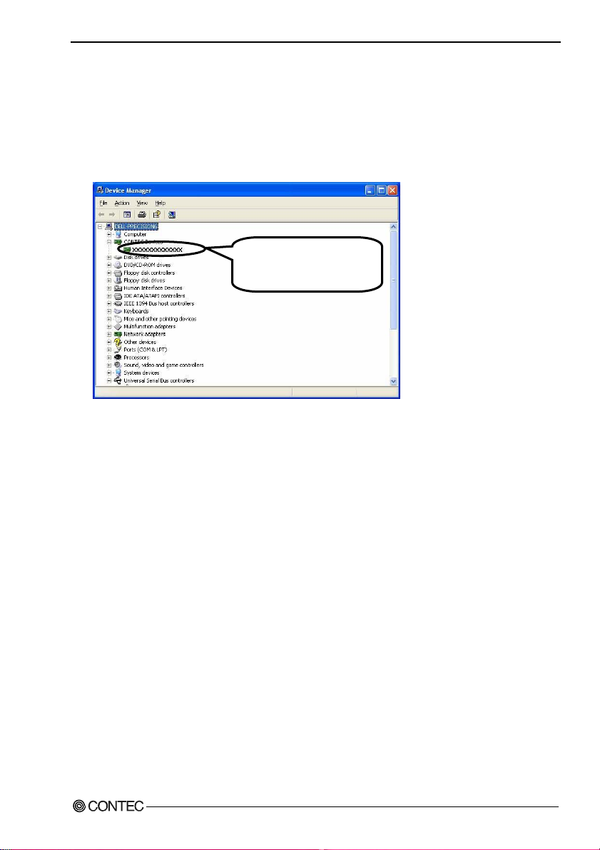
(1) Starting Device Manager.
From [Start] menu, click on [Settings]-[Control Panel]-[System] and then click on [Device
Manager] button in [Hardware] tab.
* The name of the connected
product will be displayed.
- DIO-24DY-USB
- In the case of Windows 98
Right-click on [My Computer] and select [Properties] to start device manager.
DIO-24DY-USB
13
Page 19

2. Setup
(2) Setting the Device Name.
Right-clicking on the product name and selecting [Properties] displays [Product Properties].
Open [Common Settings] tab and enter arbitrary name in the editing box for device name. (Default
name also can be used.)
* The name of the connected
product will be displayed.
- DIO-24DY-USB
* The product-specific number will be displayed as the serial number.
CAUTION
USB driver can not be used without settings. Settings must be performed.
(3) Clicking on [OK] button.
Device name is set by clicking [OK] button.
Points
- When the application developed by users is running on another PC, please perform foregoing
operation on the target computer. (No need to install software introduced on next page)
- Please use the device name specified in last step for initialization function when initialization is
performed using API function. When running on other PC, it can run without changing the
application for the same device name being specified.
DIO-24DY-USB
14
Page 20

2. Setup
Step 4 Checking Operations with the Diagnosis Program
Use the diagnosis program to check that the product and driver software w ork normally, thereby you can
confirm that they have been set up correctly.
What is the Diagnosis Program?
The diagnosis program diagnoses the states of the product and driver software.
It can also be used as a si mple ch ec k er when an ex t ern al dev i ce i s actu all y co nn ect ed .
Using the “Diagnosis Report” feat ure reports the driver settings, the presence or absence of the product,
I/O status, and interrupt status.
Using the Diagnosis Program
Starting the Diagnosis Program
Click [Diagnosis] on the Properties page to start the diagnosis program.
* The name of the connected
product will be displayed.
- DIO-24DY-USB
DIO-24DY-USB
15
Page 21
2. Setup
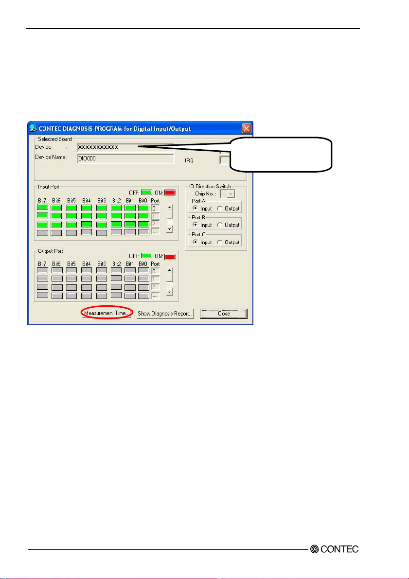
Checking Digital Inputs and Outputs
The main panel of the Diagnosis Program appears.
You can check the current operation states of the Product in the following boxes:
“Input Port” : Displays input values bit by bit at fixed time intervals.
“Output Port” : Mouse operation allows the data to output or display.
* The name of the connected
product will be displayed.
- DIO-24DY-USB
To use the function executi on time measurem ent feature, click on t he [Measurem ent Time] button. Enter
the I/O start port and the number of ports, then press the measurement button. The time for each
execution of a function will be measured.
DIO-24DY-USB
16
Page 22

2. Setup
Diagnosis Report
(1) Clicking on the [Show Diagnosis Report] button displays detailed data such as product settings and
the diagnosis results while saving them in text format.
The Diagnosis Program performs “Product presence/absence check”, “driver file test”, “product
setting test”, and so on.
CAUTION
Before executing diagnosis report output, unplug the cable from the Product.
(2) A diagnosis report is displayed as shown below.
* The name of the connected
product will be displayed.
- DIO-24DY-USB
Click on [Show
Diagnosis Report].
DIO-24DY-USB
* The name of the connected
product will be displayed.
- DIO-24DY-USB
17
Page 23

2. Setup
DIO-24DY-USB
18
Page 24

3. External Connection
3. External Connection
This chapter describes the interface connectors on the product.
Check the information available here when connecting an external device.
Using the On-terminal Connectors
Connecting a terminal to a Connector
To connect an external device to t his terminal, pl ug the cable from the device i nto the interface connector
(CN1, CN2) shown below.
CN2 CN1
Figure 3.1. Interface Connectors and Mating Connectors
DIO-24DY-USB
19
Page 25

3. External Connection
Connector Pin Assignment
CN1
14 --- DGND
13 --- PA00
12 --- PA01
11 --- PA02
10 --- PA03
9 --- PA04
8 --- PA05
7 --- PA06
6 --- PA07
5 --- PC00
4 --- PC01
3 --- PC02
2 --- PC03
1 --- DGND
DGND --- 1
PB07 --- 2
PB06 --- 3
PB05 --- 4
PB04 --- 5
PB03 --- 6
PB02 --- 7
PB01 --- 8
PB00 --- 9
PC07 --- 10
PC06 --- 11
PC05 --- 12
PC04 --- 13
DGND --- 14
CN2
Figure 3.2. Pin Assignment of CN1 Figure 3.3. Pin Assignment of CN2
Table 3.1. Signal name of CN1 and CN2
PA00 - PA07, PB00 - PB07, PC00 - PC07 Digital I/O signals
DGND Common digital ground for digital I/O signals
Relationships between Logical Ports/Bits and Connector Signal Pins
The following table lists the relationships between the connector signal pins and the logical port/bit
numbers used for I/O functions.
Table 3.2. Logical Ports, Logical Bits, and Connector Signal Pins
D7 D6 D5 D4 D3 D2 D1 D0
I/O Logical Ports0
I/O Logical Ports 1
I/O Logical Ports 2
[xx] represents a logical bits
PA7
PB7
PC7
Note : PAx, PBx, PCx represents an I/O signal of CN1
CAUTION
The logical port and logical bit numbers are virtual port and bit numbers that enable programming
independent of board I/O addresses or board types.
[7]
[15]
[23]
PA6
PA5
PA4
PA3
PA2
PA1
[6]
PB6
[14]
PC6
[22]
[5]
PB5
[13]
PC5
[21]
[4]
PB4
[12]
PC4
[20]
[3]
PB3
[11]
PC3
[19]
[2]
PB2
[10]
PC2
[18]
[1]
PB1
[9]
PC1
[17]
PA0
[0]
PB0
[8]
PC0
[16]
DIO-24DY-USB
20
Page 26

3. External Connection
Cable connection
When connecting the product to an external device, you can use the supplied connector plug.
For wiring, strip off approximately 9 - 10mm of the covered part of a wire rod and then insert it to the
opening. After the insertion, secure the wire rod with screws.
Compatible wires are AWG 28 - 16.
CAUTION
Removing the connector plug by grasping the cable can break the wire.
Figure 3.4. Connecting an Interface Connector and Connectors That Can Be Used
9 - 10mm
- Applicable plug(accessory bundled)
14 pin (Screw Terminal)
Plug header
DIO-24DY-USB
21
Page 27
3. External Connection
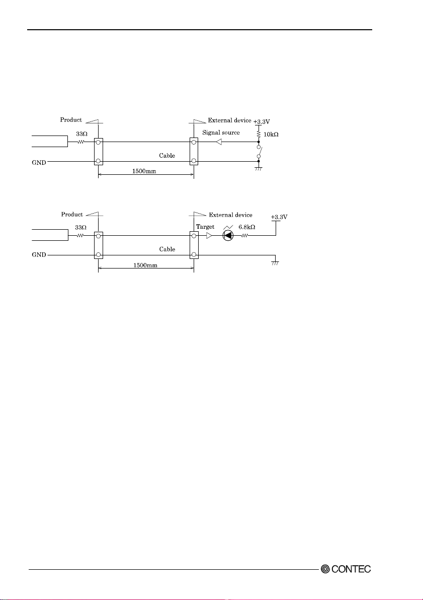
Connecting I/O Signals
As I/O signals are LVTTL (3.3V) level signals, the total cable length should be within 1.5 m.
The input is provided with an input protective resistor (33Ω).
GND is common to all I/O pins.
Figure 3.5. Input Circuit
Figure 3.6. Output Circuit
If the signal source is affected by noise or distant from the produc t, the produ ct may fail to input ac curate
data depending on the connection.
I/O signals are LVTTL-level active high signals. When the external input signal is LVTTL level, the
Low level represents logic 0 and the High level represents logic 1. When the program outputs 0 and 1,
the product outputs the Low and High level signals, respectively.
DIO-24DY-USB
22
Page 28

4. Application Development
4. Application Development
Please reference to online help and sample program when developing applications.
Reference to Online Help
Click on [Programs]-[CONTEC API-USBP(WDM)]-[API-USBP(W32) Help] from [Start] menu.
The information for application development, such as function reference is provided in
[API-USBP(W32) Help].
Detailed introduction to search method for help should be found from [How to navigate Help] in the
help.
Printing Function Reference
Clicking on Print button from
online help prints the page being
displayed. It can be printed
entirely as follows in the case of
referencing to printing function.
As figure shown on the right,
selecting
on Print button prints all the
topics under the mark selected at
a time.
mark and clicking
DIO-24DY-USB
23
Page 29

4. Application Development
Sample Program
To run a sample program, click on
[Programs] - [CONTEC
API-USBP(WDM)] - [DIO] [Sample Name] from [Start] menu.
Distributing Developed Application
Please distribute the developed application with USB driver in supplied CD-ROM.
DIO-24DY-USB
24
Page 30

4. Application Development
Returning to Initial State
This is the method of returning to initial state. It is suggested that you should return to initia l st ate and
perform installation again when the operation is losing stabilization.
Moreover, the method of returning to the initial state is different depending on OS. Please initialize it by
the method of suitable for OS used.
Step1 Uninstalling Driver and the development environment
- Uninstall procedure for Windows 7, Vista
<Uninstall of device driver>
1. Run Device Manager. From [My Computer] - [Control Panel], select [System] and then select the
[Device Manager] tab. (You can also open Device Manager by right clicking on My Computer and
selecting Properties .)
2. All of the hardware that uses the API-TOOL(WDM) driver is registered under the CONTEC
Devices tree.
Open the device tree, select the hardware to uninstall, and then right-click the hardware.
From the popup menu, select [Uninstall].
3. A dialog box opens asking you to confirm whether to uninstall. Select the [Delete the driver
software for this device] checkbox, and then click [OK].
DIO-24DY-USB
25
Page 31

4. Application Development
<Uninstall of development environment >
Use [My Computer] - [Control Panel] - [Programs and Features] to uninstall the development
environment. Select [CONTEC API-***(WDM) VerX.XX (development environment)] and then click
[Uninstall].
* "***" contains the driver category name (AIO, CNT, DIO, etc.).
- Uninstall procedure for Windows XP and Windows 2003 Server
<Uninstall of device driver>
Use [My Computer] - [Control Panel] - [Add and Remove Programs] to uninstall the device driver.
Select [Windows driver package - CONTEC (****)] and then click [Change/Remove].
* "***" contains the driver category name (caio, ccnt, cdio, csmc, etc.).
<Uninstall of development environment>
Use [My Computer] - [Control Panel] - [Add and Remove Programs] to uninstall the development
environment. Select [CONTEC API-***(WDM) VerX.XX (development environment)] and then click
[Change/Remove].
* "***" contains the driver category name (AIO, CNT, DIO, etc.).
DIO-24DY-USB
26
Page 32
4. Application Development
- Uninstall procedure for Windows Me
<Uninstall of device driver>
Use [My Computer] - [Control Panel] - [Add and Remove Applications] to uninstall the device driver.
Select [CONTEC API-***(WDM) driver] and then click [Add/Remove].
* "***" contains the driver category name (AIO, CNT, DIO, etc.).
<Uninstall of development environment>
Use [My Computer] - [Control Panel] - [Add and Remove Programs] to uninstall the development
environment.
Select [CONTEC API-***(WDM) VerX.XX (development environment)] and then click
[Add/Remove].
* "***" contains the driver category name (AIO, CNT, DIO, etc.).
- Uninstall procedure for Windows 98, 98SecondEdition
<Uninstall of device driver>
Use [My Computer] - [Control Panel] - [Add and Remove Applications] to uninstall the device driver.
Select [CONTEC API-***(WDM) driver] and then click [Add/Remove].
* "***" contains the driver category name (AIO, CNT, DIO, etc.).
<Uninstall of development environment>
Use [My Computer] - [Control Panel] - [Add and Remove Applications] to uninstall the development
environment.
Select [CONTEC API-***(WDM) VerX.XX (development environment)] and then click
[Add/Remove].
* "***" contains the driver category name (AIO, CNT, DIO, SMC, etc.).
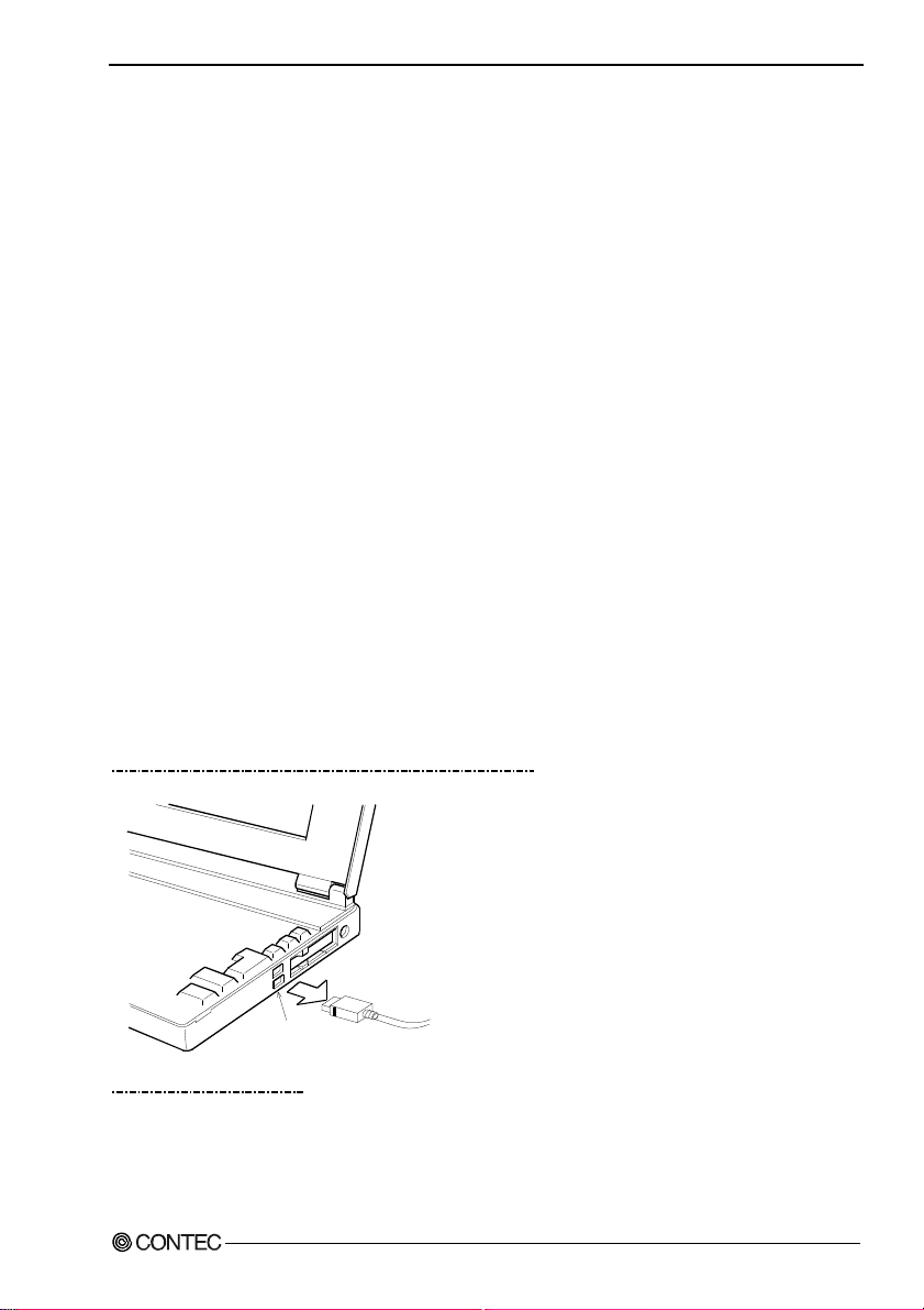
Step2 Drawing USB cable from a PC
USB port
Step3 Restarting
DIO-24DY-USB
27
Page 33

4. Application Development
DIO-24DY-USB
28
Page 34

5. Functions
5. Functions
This section describes the functions of the product.
I/O Function
The product can input/output a total of 24 channels of LVTTL-level active-high digital signals.
There are three sets (8-bit) of I/O ports, which can be controlled by a program to input/output data.
DIO-24DY-USB
29
Page 35

5. Functions
DIO-24DY-USB
30
Page 36

6. About Hardware
6. About Hardware
Hardware specification
Table 6.1. Specification
Item Specifications
I/O
Number of I/O channels 24 channels
I/O format LVTTL-level (Positive logic)
Input resistance 33
Output rating 3.3VDC 8mA
Response time Within 200nsec *1
USB
Bus specification USB Specification 2.0/1.1 standard
USB transfer rate 12Mbps(Full-speed), 480Mbps(High-speed) *1
Power supply Bus power
Common
Connector 14 pin (screw-terminal) plug header
Number of terminals
used at the same time
Current consumption
(Max.)
Operating conditions 0 - 50ºC, 10 - 90%RH(No condensation)
Allowable distance of
signal extension
Physical dimensions
(mm)
Weight 70g (Not including the USB cable, attachment)
Attached cable USB cable 1.8m
Compatible wires AWG28 - 16
*1 Actual throughput is hundreds of μ seconds (This depends on the host PC environment used (OS and USB host
controller).)
*2 As a USB hub is also counted as one device, you cannot just connect 127 USB terminals.
Ω
127 terminals (Max.) *2
5VDC 250mA
Approx. 1.5m (depending on wiring environment)
64(W) x 62(D) x 24(H) (exclusive of protrusions)
DIO-24DY-USB
31
Page 37

6. About Hardware
Physical dimensions
62
24
14
9
64
[mm]
9
Figure 6.1. Physical dimensions
Block Diagram
GND
D+
VCC
D-
USB Connector
USB
Controll
&
CPU
Switching input and output
LVT TL
Driver
Protection
resistance
Digital
Output
Digital
Input
I/O Connector
Figure 6.2. Block Diagram
DIO-24DY-USB
32
Page 38

DIO-24DY-USB
User’s Manual
CONTEC CO., LTD. February 2010 Edition
3-9-31, Himesato, Nishiyodogawa-ku, Osaka 555-0025, Japan
Japanese http://www.contec.co.jp/
English http://www.contec.com/
Chinese http://www.contec.com.cn/
No part of this document may be copied or reproduced in any form by any means without prior written
consent of CONTEC CO., LTD. [02052010]
[03102006] Management No. A-51-219
[02052010_rev9] Parts No. LYFZ716
 Loading...