

Page 1

PC-HELPER
Digital I/O Board
for PCI Express
Low Profile
DIO-1616T-LPE
User’s Guide
CONTEC CO.,LTD.
Page 2
Check Your Package
Thank you for purchasing the CONTEC product.
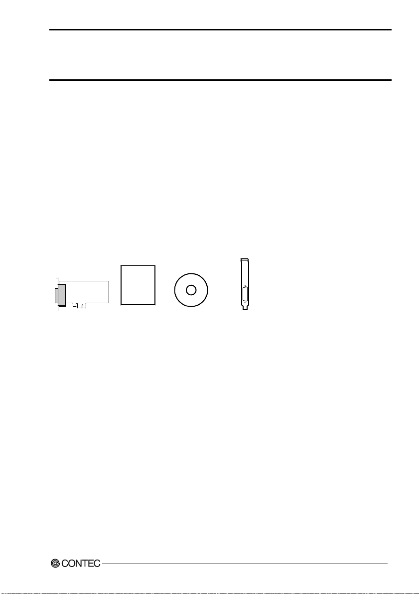
The product consists of the items listed below.
Check, with the following list, that your package is co mplete. If you di scover dama ged or missing it ems,
contact your retailer.
Product Configuration List
- Board [DIO-1616T-LPE]…1
- First step guide… 1
- CD-ROM *1 [API-PAC(W32)]…1
- Standard-sized bracket…1
*1 The CD-ROM contains the driver software and User’s Guide (this guide)
Board
First step guide
CD-ROM
[COM Setup Disk]
Standard size
bracket
DIO-1616T-LPE i
Page 3

Copyright
Copyright 2006 CONTEC CO., LTD. ALL RIGHTS RESERVED.
No part of this document may be copied or reproduced in any form by any means without prior written
consent of CONTEC CO., LTD.
CONTEC CO., LTD. makes no commitment to update or keep current the information contained in this
document. The information in this document is subject to change without notice.
All relevant issues have been considered in the preparation of this document. Should you notice an
omission or any questionable item in this document, please feel free to notify CONTEC CO., LTD.
Regardless of the foregoing statement, CONTEC assumes no responsibility for any errors that may
appear in this document or for results obtained by the user as a result of using this product.
Trademarks
MS, Microsoft, Windows are trademarks of Microsoft Corporation. Other brand and product names are
trademarks of their respective holder.
ii
DIO-1616T-LPE
Page 4

Table of Contents
Check Your Pack ag e............................................................................................................................i
Copyright ............................................................................................................................................ii
Trademarks ......................................................................................................................................... ii
Table of Con tents...............................................................................................................................iii
1. BEFORE USING THE PRODUCT 1
About the Bo ard.................................................................................................................................. 1
Features........................................................................................................................................ 1
Support Softw ar e ......................................................................................................................... 2
Cable & Connect or ( Op ti on ) ...................................................................................................... 3
Accessories ( Op tio n ) .................................................................................................................. 3
Customer Supp o rt ............................................................................................................................... 4
Web Site....................................................................................................................................... 4
Limited Thre e -Y ea rs Wa r ra nt y .......................................................................................................... 4
How to Obtain Serv ic e ....................................................................................................................... 4
Liability............................................................................................................................................... 4
Safety Precau t ion s .............................................................................................................................. 5
Safety Infor mat i on ....................................................................................................................... 5
Handling Pre ca u tio n s................................................................................................................... 6
Environment................................................................................................................................. 7
Inspection..................................................................................................................................... 7
Storage ......................................................................................................................................... 7
Disposal ....................................................................................................................................... 7
2. SETUP 9
What is Setup? .................................................................................................................................... 9
Using the Board un de r W in do w s Us in g th e D riv e r Lib ra r y A PI -PAC ( W 3 2) ............................ 9
Using the Board under Windows Using Software Other than the Driver Library
API-PAC(W32 )............................................................................................................................ 9
Using the Board un d er an OS O th e r th an Wi n do w s ................................................................. 10
Step 1 Installi n g the Software .......................................................................................................... 11
Starting the I ns t all P r og r a m....................................................................................................... 11
Selecting the Di git a l I/ O Dr iv er ................................................................................................12
Executing the In s tal l a tio n ..........................................................................................................13
Step 2 Setting th e H ar d wa r e .............................................................................................................14
Replacing the B rac k et................................................................................................................ 14
Parts of the Bo ard an d F ac to r y D ef au l ts ................................................................................... 15
Setting the Bo ard ID .................................................................................................................. 15
Plugging the Board ....................................................................................................................1 6
DIO-1616T-LPE
iii
Page 5

Step 3 Installi ng th e H ard w a re ......................................................................................................... 17
Turning on the PC...................................................................................................................... 17
Setting with th e Fou n d Ne w H a rd war e W iz a rd......................................................................... 17
Step4 Initializing the S o f tware................................................................................................ ......... 20
Invoking API-TOOL Configuration.......................................................................................... 20
Updating the S e ttin g s................................................................................................................. 20
Step 5 Checking Op e r ati o n s w ith th e D i ag no s is P rog ra m ...............................................................21
What is the Di agno s is P r og r a m?................................................................................................ 21
Check Method ............................................................................................................................21
Using the Di agnosis Progr am.................................................................................................... 22
Setup Troubl esh oo ti n g...................................................................................................................... 25
If your proble m c a nno t b e r eso lv ed........................................................................................... 25
3. EXTERNAL CONNECTION 27
How to connect the c on n ec to r s......................................................................................................... 27
Connector shap e......................................................................................................................... 27
Connector Pin Ass i gnment ........................................................................................................28
Relationships be tw ee n AP I-P AC ( W32 ) Log ic a l Po rt s/ Bi ts a nd Co nn e cto r Sig na l Pin s.......... 29
Connecting In pu t Si gn al s.................................................................................................................. 30
Input Circu it...............................................................................................................................3 0
Connecting a S wi tc h ..................................................................................................................30
Output Circuit ................................................................................................................................... 31
Output Circuit ............................................................................................................................ 31
Connection to the LE D .............................................................................................................. 31
4. FUNCTION 33
Data I/O Func tio n ............................................................................................................................. 33
Data Input................................................................................................................................... 33
Data Output................................................................................................................................ 33
Monitoring Ou tp ut D at a ............................................................................................................. 33
Digital Filter...................................................................................................................................... 34
Digital Filter Function Principle................................................................................................ 34
Set Digital F ilt e r Time............................................................................................................... 34
Interrupt Con tr ol Fu n ct io n................................................................................................................ 35
Disabling/en ab l ing I nt e rr up ts .................................................................................................... 35
Selecting th e In t e rru p t E dg e ...................................................................................................... 35
Clearing the Inte rru pt St atu s an d In t er ru p t Si g n al .................................................................... 35
iv
DIO-1616T-LPE
Page 6

5. ABOUT SOFTWARE 37
CD-ROM Directo r y S t ru c tu re .......................................................................................................... 37
About Software for Windo ws........................................................................................................... 38
Accessing the He lp F il e........................................................................................................ ..... 38
Using Sample Programs ............................................................................................................ 39
Uninstalling the Dr i v er Li b ra rie s .............................................................................................. 41
About Software for Linux ....................................................................................................... .......... 42
Driver Softwa re In s tal l Pro c ed ur e .............................................................................................42
Accessing the He lp F il e........................................................................................................ ..... 43
Using Sample Programs ............................................................................................................ 43
Uninstalling the driver............................................................................................................... 43
6. ABOUT HARDWARE 45
For detailed t e chn ic a l in f o r mat io n ................................................................................................... 45
Hardware spe cification..................................................................................................................... 45
Block Diagra m.................................................................................................................................. 47
DIO-1616T-LPE
v
Page 7

vi
DIO-1616T-LPE
Page 8

1. Before Using the Product
1. Before Using the Product
This chapter provides information you should know before using the product.
About the Board
This product is a PCI Express bus-compliant interface board for input/output of unisolated TTL-level
digital signals.
This product can input and output up to 16 channels. You can use all of the input signals as interrupt
inputs.
This product supports a Low Profile size slot and, if replaced with the supplied bracket, supports a
standard size slot, too.
Using the bundled API function library packa ge [API-P AC(W32)], you can create Windows applicati on
software for this board in your favorite programming language supporting Win32 API functions, such as
Visual Basic or Visual C++.
Features
- Unisolated TTL-level input x 16 channels,
Unisolated open collector output x 16 channels
- Unisolated TTL-level (positive logic) input/output enabling fast response (within 200nsec)
- You can use all of the input signals as interrupt inputs.
You can also disable or enable the interrupt in bit units and select the interrupt edge.
- This product has a digital filter to prevent input signals from carrying noise or a chattering.
- The rated output signal is up to 30VDC, 40mA per one signal.
- Support for both of low-profile and standard size slots (interchangeable with a bundled bracket)
- Equipped with the same function as the PCI board PIO-16/16T(LPCI)H
- The connector shape and the signal assignment for the connector is compatible with the
PIO-16/16T(LPCI)H.
DIO-1616T-LPE
1
Page 9

1. Before Using the Product
Support Software
You should use CONTEC support software according to your purpose and development environment.
Driver Library
API-PAC(W32)
API-PAC(W32) is the library software that provides the commands for CONTEC hardware products in
the form of Windows standard Win32 API functions (DLL). It makes it easy to create high-speed
application software taking adva nta g e of the CONTE C har dware usi ng va r ious programming language s
that support Win32 API functions, such as Visual Basic and Visual C++.
It can also be used by the installed diagnosis program to check hardware operations.
CONTEC provides download services (at http://www.contec.com/apipac/ ) to supply the updated dri vers
and differential files.
For details, read Help on the bundled CD-ROM or visit the CONTEC’s Web site.
< Operating environment >
OS Windows XP, Server 2003, 2000
Adaptation language
Visual C++ .NET, V i sual C# . N ET, Vi s u al Ba si c . N ET, Vis u a l C+ +, Vi s u al Ba sic,
Delphi, C++Builder
Linux version of digital I/O driver
This driver is used to control CONTEC digital I/O boards (cards) from within Linux.
You can control CONTEC I/O boards easily using the shared library called from the user applicatio n, the
device driver (module) for kernel version, and the board (card) configuration program (config).
CONTEC provides download services (at http://www.contec.com/apipac/ ) to supply the updated drivers
and differential files.
For details, read Help on the bundled CD-ROM or visit the CONTEC’s Web site.
(Bundled)
, etc..
API-DIO(LNX)
(Supplied: Stored on the API-PAC(W32) CD-ROM)
< Operating environment >
OS RedHatLinux, TurboLinux, etc..
Adaptation language gcc, etc..
Data acquisition VI library for LabVIEW
(For details on supported distributions, refer to Help available after installation.)
VI-DAQ
(Available for downloading (free of charge) from
the CONTEC web site.)
This is a VI library to use in National Instruments LabVIEW.
VI-DAQ is created with a function form similar to that of LabVIEW's Data Ac quisition VI, allowing you
to use various devices without complicated settings.
See http://www.contec.com/vidaq/ for details and download of VI-DAQ.
2
DIO-1616T-LPE
Page 10

1. Before Using the Product
Cable & Connector (Option)
Shield Cable with Two 50-Pin Mini-Ribbon Connector : PCB50PS-0.5P(0.5m)
: PCB50PS-1.5P(1.5m)
Shield Cable with One 50-Pin Mini-Ribbon Con nector : PCA50PS-0.5P(0.5m)
: PCA50PS-1.5P(1.5m)
Connection Conversion 0.5m Shield Ca ble (5 0-Pin Ribbon→37-Pin D-SUB)
: PCE50/37PS-0.5P(0.5m)
Accessories (Option)
Screw Terminal Unit(M3 terminal block, 50 points) : EPD-50A *1
Screw Terminal Unit(M3 terminal block, 37 points) : EPD-37A *2
Screw Terminal Unit(M3.5 terminal block, 37 points) : EPD-37 *2
General Purpose Terminal :DTP-3A *3
Termination Panel (M3) : DTP-3(PC) *3
Screw Terminal : DTP-4A *3
Termination Panel : DTP-4(PC) *3
Signal Monitor for Digital I/O : CM-32(PC)E *2
*1 PCB50PS-*P optional cable is required separately.
*2 PCE50/37PS-0.5P and PCB37P or PCB37PS optional cable is required separately.
*3 PCE50/37PS-0.5P optional cable is required separately.
* Check the CONTEC’s Web site for more information on these options.
DIO-1616T-LPE
3
Page 11

1. Before Using the Product
Customer Support
CONTEC provides the followi ng support s ervices for y ou to use CONTEC produc ts more effici ently and
comfortably.
Web Site
Japanese http://www.contec.co.jp/
English http://www.contec.com/
Chinese http://www.contec.com.cn/
Latest product information
CONTEC provides up-to-date information on products.
CONTEC also provides product manuals and various technical documents in the PDF.
Free download
You can download updated driver software and differential files as we ll as sample program s available in
several languages.
Note! For product information
Contact your retailer if you have any technical question about a CONTEC product or need its price,
delivery time, or estimate information.
Limited Three-Years Warranty
CONTEC products are warranted by CONTEC CO., LTD. to be free from defects in material and
workmanship for up to three years from the date of purchase by the original purchaser.
Repair will be free of charge only when this device is returned freight pre paid with a c opy of the ori ginal
invoice and a Return Merchandise Authorization to the distributor or the CONTEC group office, from
which it was purchased.
This warranty is not applicable for scratches or normal wear, but only for the electronic circuitry and
original boards. The warranty is not applicable if the device has been tampered with or damaged through
abuse, mistreatment, neglect, or unreaso nable use, or if the original invoice is not included, in which case
repairs will be considered beyond the warranty policy.
How to Obtain Service
For replacement or repair, return the device freight prepaid, with a copy of the original invoice. Please
obtain a Return Merchandise Authorization Number (RMA) from the CONTEC group office where you
purchased before returning any product.
* No product will be accepted by CONTEC group without the RMA number.
Liability
The obligation of the warrantor is solely to repair or replace the product. In no event will the warrantor
be liable for any incidental or consequentia l damages due to s uch defect or consequences t hat arise from
inexperienced usage, misuse, or malfunction of this device.
4
DIO-1616T-LPE
Page 12
1. Before Using the Product
Safety Precautions
Understand the following definitions and precautions to use the product safely.
Safety Information
This document provides safety i nformation usin g the following sym bols to prevent accidents resulting in
injury or death and the destructio n of equipment an d resources. U nderstand t he meanings of these labels
to operate the equipment safely.
DANGER
WARNING
CAUTION
DANGER indicates an imminently hazardous situation which, if not avoided, will
result in death or serious injury.
WARNING indicates a potentially hazardous situation which, if not avoided, could
result in death or serious injury.
CAUTION indicates a potentially hazardous situation which, if not avoided, may
result in minor or moderate injury or in property damage.
DIO-1616T-LPE
5
Page 13

1. Before Using the Product
Handling Precautions
DANGER
Do not use the product where it is exposed to flamm able or corrosi ve gas. Doing so ma y result in an
explosion, fire, electric shock, or failure.
CAUTION
- There are switches on the board that need to be set in advance. Be sure to check these before
installing the board.
- Only set the switches and jumpers on the board to the specified settings.
Otherwise, the board may malfunction, overheat, or cause a failure.
- Do not strike or bend the board. Doing so could damage the board.
Otherwise, the board may malfunction, overheat, cause a failure or breakage.
- Do not touch the board's metal plated terminals (edge connector) with your hands.
Otherwise, the board may malfunction, overheat, or cause a failure.
If the terminals are touched by someone's hands, clean the terminals with industrial alcohol.
- Do not install or remove the board to or from the extension slot while the computer's power is turned on.
And also do not connect the board and external device while the power is turned on.
Otherwise, the board may malfunction, overheat, or cause a failure.
Be sure that the personal computer or the I/O extension unit power is turned off.
- Make sure that your PC or extension unit can supply ample power to all the boards installed.
Insufficiently energized boards could malfunction, overheat, or cause a failure.
- The specifications of this product are subject to change without notice for enhancem ent and quality
improvement.
Even when using the product continuously, be sure to read the manual and understand the contents.
- Do not modify the product. CONTEC will bear no responsibility for any problems, etc., resulting
from modifying this product.
- Regardless of the foregoing statements, CONTEC is not liable for any damages whatsoever
(including damages for loss of business profits) arising out of the use or inability to use this
CONTEC product or the information contained herein.
6
DIO-1616T-LPE
Page 14
1. Before Using the Product
Environment
Use this product in the following environment. If used in an unauthorized environment, the board may
overheat, malfunction, or cause a failure.
Operating temperature
0 - 50°C
Humidity
10 - 90%RH (No condensation)
Corrosive gases
None
Floating dust particles
Not to be excessive
Inspection
Inspect the product periodically as follows to use it safely.
- Check that the bus connector
of the board and its cable have
been plugged correctly.
- Check that the board has
no dust or foreign matter adhering.
- The gold-plated leads of the bus connector
have no stain or corrosion.
Storage
When storing this product, keep it in its original packing form.
(1) Put the board in the storage bag.
(2) Wrap it in the packing material, and then put it in the box.
(3) Store the package at room temperature at a place free from direct sunlight, moisture, shock,
vibration, magnetism, and static electricity.
Disposal
When disposing of the product, follow the disposal procedures stipulated under the relevant laws and
municipal ordinances.
DIO-1616T-LPE
7
Page 15

1. Before Using the Product
8
DIO-1616T-LPE
Page 16

2. Setup
2. Setup
This chapter explains how to set up the board.
What is Setup?
Setup means a series of steps to take before the product can be used.
Different steps are required for software and hardware
The setup procedure varies with the OS and applications used.
Using the Board under Windows
Using the Driver Library API-PAC(W32)
This section describes the setup procedure to be performed before you can start developing application
programs for the board using the bund led C D -ROM “Driver Library API-PAC(W32)”.
Taking the following steps sets up the software and hardware. You can use the diagnosis program later
to check whether the software and hardware function normally.
Step 1 Installing the Software
Step 2 Setting the Hardware
Step 3 Installing the Hardware
Step 4 Initializing the Software
Step 5 Checking Operations with the Diagnosis Program
If Setup fails to be performed normally, see the “Setup Troubleshooting” section at the end of this
chapter.
Using the Board under Windows
Using Software Other than the Driver Library API-PAC(W32)
For setting up software other than API-PAC(W32), refer to the manual for that software. See also the
following parts of this manual as required.
This chapter Step 2 Setting the Hardware
This chapter Step 3 Installing the Hardware
Chapter 3 External Connection
Chapter 6 About Hardware
DIO-1616T-LPE
9
Page 17

2. Setup
Using the Board under an OS Other than Windows
For using the board under an Linux, see the following parts of this manual.
This chapter Step 2 Setting the Hardware
Chapter 3 External Connection
Chapter 5 About Software
Chapter 6 About Hardware
For using the board under an OS other than Windows and Linux, see the following part s of this manual.
This chapter Step 2 Setting the Hardware
Chapter 3 External Connection
Chapter 6 About Hardware
10
DIO-1616T-LPE
Page 18

2. Setup
Step 1 Installing the Software
This section describes how to install the Driver libraries.
Before installing the hardware on your PC, install the Driver libraries from the bundled API-PAC(W32)
CD-ROM.
The following description assumes the operating system as Windows XP. Although some user
interfaces are different depending on the OS used, the basic procedure is the same.
Starting the Install Program
(1)
Load the CD-ROM [API-PAC(W32)] on your PC.
(2)
The API-PAC(W32) Installer window appears automatically.
If the panel does not appear, run (CD-ROM drive letter):\AUTORUN.exe.
(3)
Click on the [Install Development or Execution Environment] button.
CAUTION
Before installing the software in Windows XP, 2000, or NT, log in as a user with administrator
privileges.
DIO-1616T-LPE
11
Page 19

2. Setup
Selecting the Digital I/O Driver
(1)
The following dialog box appears to select “Driver Type” and “Install Type”.
(2)
Select “Digital I/O API-DIO(98/PC)”.
(3)
Select “Driver, Help, etc… (Full install)”.
(4)
Click on the [Install] button.
12
DIO-1616T-LPE
Page 20

2. Setup
Executing the Installation
(1) Follow the on-screen instructions to proceed to install.
(2) When the required files have been copied, the “Perform a hardware setup now” and “Show readme
file” check boxes are displayed.
When you are installing the software or hardware for the first time:
1) Uncheck “Perform a hardware setup now”.
2) Click on the [Finish] button. Go to Step 2 to set and plug the hardware.
*When the hardware has already been installed:
Check “Perform a hardware setup now”, then go to Step 4 “Initializing the Software”.
You have now finished installing the software.
DIO-1616T-LPE
13
Page 21

2. Setup
Step 2 Setting the Hardware
This section describes how to set the board and plug it on your PC.
The board has some switches to be preset.
Check the on-board switches before plugging the board into an extension slot.
The board can be set up even with the factory defaults untouched. You can change board settings later.
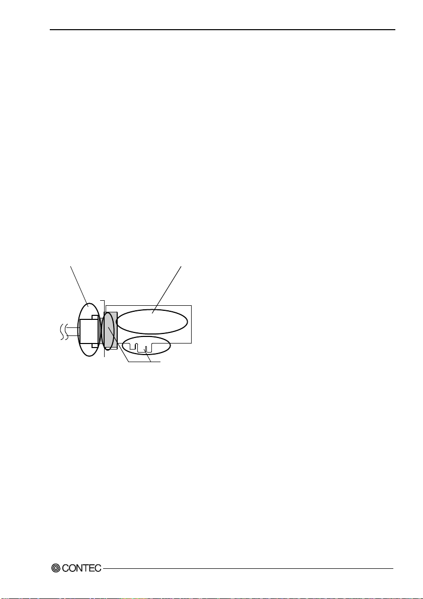
Replacing the Bracket
This board is shipped with a Low Profile size bracket mounted. To plug the board into a standard size
slot, replace the bracket with the bundled standard size bracket. The replacing method is as follows :
Standard size bracke t
- Remove the screws and replace it
with the Standard size bracket.
Low Profile size bracket
Screw
Use a flathead screwdriver or hexagonal
spanner to undo and tighten the screws.
Figure 2.1. Replacing the Bracket
14
DIO-1616T-LPE
Page 22

2. Setup
Parts of the Board and Factory Defaults
Figure 2.2. shows the names of major parts on the board.
Note that the switch setting shown below is the factory default.
- Interface connector
(CN1)
- Board ID setting switch
SW1
BOARD ID
(SW1)
SW1
BOARD ID
8
9
A
7
6
B
5
4
3
E
2
F
1
0
C
D
Figure 2.2. Component Locations
Setting the Board ID
If you install two or more boards on one personal computer, assign a different ID value to each of the
boards to distinguish them.
The board IDs can be set from 0 to Fh to identify up to sixteen boards.
If only one board is used, the original factory setting (Board ID = 0) should be used.
Setting Procedure
To set the board ID, use the rotary switch on the boar d. Tur n the SW1 knob t o set the b oard ID as show n
below.
SW1
BOARD ID
8
9
A
7
B
6
C
5
D
4
3
E
2
F
Factory setting:
1
0
(Board ID = 0)
Figure 2.3. Board ID Settings (SW1)
DIO-1616T-LPE
15
Page 23

2. Setup
Plugging the Board
(1) Before plugging the board, shut down the syste m, unplug th e power cod e of you r PC.
(2) Remove the cover from the PC so that the board can be mounted.
(3) Plug the board into an extension slot.
(4) Attach the board bracket to the PC.
(5) Put the cover back into place.
CAUTION
- Do not touch the board's metal plated terminals (edge connector) with your hands.
Otherwise, the board may malfunction, overheat, or cause a failure.
If the terminals are touched by someone's hands, clean the terminals with industrial alcohol.
- Do not install or remove the board to or from the slot while the computer's or extension unit’s power is
turned on.
Otherwise, the board may malfunction, overheat, or cause a failure.
Be sure that the personal computer or the I/O extension unit power is turned off.
- Make sure that your PC or extension unit can supply ample power to all the boards installed.
Insufficiently energized boards could malfunction, overheat, or cause a failure.
16
DIO-1616T-LPE
Page 24

2. Setup
Step 3 Installing the Hardware
For using an extension board un der Window s, you have to let the OS detect t he I/O addresse s and IRQ to
be used by the board. The process is referred to as installing the hardware.
In the case of using two or more boards, make sure you install one by one with the Found New Hardware
Wizard.
Turning on the PC
Turn on the power to your PC.
CAUTION
- The board cannot be properly installed unless the resources (I/O addresses and interrupt level) for
the board can be allocated. Before attempting t o install the boar d, first det ermine what PC resources
are free to use.
- The resources used by each board do not depend on the location of the PCI Expr ess bus s lot or th e
board itself. If you remove two or more boards that have already been installed and then remount
one of them on the computer, it is unknown that which one of the sets of resources previou sly
assigned to the two boards is assigned to the remounted board. In this case, you must check the
resource settings.
Setting with the Found New Hardware Wizard
(1) First, “PCI Standard PCI to PCI Bridge” will be checked and end automatically.
(2) The “Found New Hardware Wizard” will be started.
Select “Install from a list or specific location[Advanced]”, then click on the [Next] button.
DIO-1616T-LPE
17
Page 25

2. Setup
(3) Specify that folder on the CD-ROM which contains the setup information (INF) file to register the
board.
* The name of the board
you have just added is
displayed.
DIO-1616T-LPE
Source folder
The setup information (INF) file is cont ai n ed in the following fo ld e r on the bundled CD-ROM.
Windows XP, 2000 \INF\Win2000\Dio\PCI
Example of specifying the folder for use under Windows XP
\INF\Win2000\Dio\PCI
18
DIO-1616T-LPE
Page 26

2. Setup
CAUTION
In Windows XP, the Hardware Wizard displays the following alert dialog box when you have
located the INF file. This dialog box appears, only indi cating that the re levant dri ver has not pas sed
Windows Logo testing, and it ca n be ign ore d without developing any problem with the operation of
the board.
In this case, click on the [Continue Anyway] button.
You have now finished installing the software.
* The name of the board
you have just added is
displayed.
- DIO-1616T-LPE
DIO-1616T-LPE
19
Page 27

2. Setup
Step4 Initializing the Software
The driver library requires the initial setting to recognize the execution environment. It is called the
initialization of the Dri ve r li br ary.
Invoking API-TOOL Configuration
(1) Open the Start Menu, then select “Programs” – “CONTEC API-PAC(W32)” – “API-TOOL
Configuration”.
(2) API-TOOL Configuration detects boards automatically.
The detected boards are listed.
Updating the Settings
(1) Select “Save settings to registry…” from the “File” menu.
You have now finished installing the initial setting of Software.
20
DIO-1616T-LPE
Page 28

2. Setup
Step 5 Checking Operations with the Diagnosis Program
Use the diagnosis program to check that the board and driver software work normally, thereby you can
confirm that they have been set up correctly.
What is the Diagnosis Program?
The diagnosis program diagnoses th e states of the board and driv er s of tware.
It can also be used as a simple checker when an ex t ern al d evi ce i s actu a ll y con ne ct ed .
Using the “Diagnosis Report” feature reports the driver settings, the presence or absence of the board,
I/O status, and interrupt status.
Check Method
Connect the board to a remote device to test the input/output and check the execution environment.
For this board, an external power supply is not needed.
The Check Mate (CM-32(PC)E) comes in handy when you check digital I/O boards.
Check the board with the factor defaults untouched.
Connection diagram
Connector
PCE50/37PS-0.5P, PCB37P or PCB37PS
Option cable
To connect a device other than the Check Mate, see Chapter 3 “External Connection”.
CM-32(PC)E
GROUP 1
7 6 5 4 3 2 1 0
GROUP 3
7 6 5 4 3 2 1 0
GROUP 0
7 6 5 4 3 2 1 0
GROUP 2
7 6 5 4 3 2 1 0
POWER
CN3
DIO-1616T-LPE
21
Page 29

2. Setup
Using the Diagnosis Program
Starting the Diagnosis Program
Select the board in the API-TOOL Configuration windows, t hen run the D iagnos is Pro gram . Foll ow t he
instructions on screen.
* The name of the board you have just added is displayed.
* The name of the board
you are testing is displayed.
- DIO-1616T-LPE
22
DIO-1616T-LPE
Page 30

Checking Digital Inputs and Outputs
The main panel of the Diagnosis Program appears.
You can check the current operation states of the board in the following boxes:
“Input Port” : Displays input values bit by bit at fixed time intervals.
“Output Port” : Mouse operation allows the data to output or display.
“Interrupt” : Displays the number of interrupts detected bit by bit.
* The name of the board
you have just added is
displayed.
- DIO-1616T-LPE
2. Setup
To use the wait time control feature, click on the [Wait Configuration] button. Use the feature when the
wait time based on the DioWait or DioWaitEx function is not normal.
To use the function execution time measurement feature, click on the [Measurement Time] button. Enter
the I/O start port and the number of ports, then press the measurement button. The time for each
execution of a function will be measured.
DIO-1616T-LPE
23
Page 31

2. Setup
Diagnosis Report
(1) Clicking on the [Show Diagnosis Report] button displays detailed data such as board settings and
the diagnosis results while saving them in text format.
The results are saved and displayed as a text file (DioRep.txt) in the install folder (Program
Files\CONTEC\API-PAC(W32)).
The Diagnosis Program performs “board presence/absence check”, “driver file test”, “board setting
test”, and so on.
CAUTION
Before executing diagnosis report output, unplug the cable from the board.
(2) A diagnosis report is displayed as shown below.
* The name of the board
you have just added is
displayed.
- DIO-1616T-LPE
Click on [Show
Diagnosis Report].
* The name of the board
you have tested is displayed.
- DIO-1616T-LPE
24
DIO-1616T-LPE
Page 32

2. Setup
Setup Troubleshooting
No output can be obtained.
Use API-TOOL Configuration to check whether the board name setting is wrong.
The board works with the Diagnosis Program but not with an application.
The Diagnosis Program is coded with API-TOOL functions. As long as the board operates with the
Diagnosis Program, it is to operate with other applications as well. In such cases, review your program
while paying attention to the following points:
- Check the arguments to functions and their return values.
- When the board is an isolat ed type, it has a tim e lag for its response between the output by a functio n
and the actual output. Consider the execution intervals between functions.
The OS won’t normally get started or detect the board. [Windows XP
Turn off the power to your PC, then unplug the board. Restart the OS and delete the board settings of
API-TOOL Configuration. Turn off the PC again, plug the board, and restart the OS. Let the OS detect
the board and use API-TOOL Configuration to register board settings.
2000]
,
If your problem cannot be resolved
Contact your retailer.
DIO-1616T-LPE
25
Page 33

2. Setup
26
DIO-1616T-LPE
Page 34

3. External Connection
3. External Connection
This chapter describes the interface connectors on the board and the external I/O circuits.
Check the information available here when connecting an external device.
How to connect the connectors
Connector shape
The on-board interface connector (CN1) is used when connecting this product and the external devices.
Interface connector (CN1)
- Con nector used
50-Pin Mini-Ribbon connector
10250-52A2JL[mfd.by 3M]
- Applilcable connector
10150-6000EL[mfd. by 3M]
CN1
* Please refer to chapter 1 for more information on the supported cable and accessories.
Figure 3.1. Interface Connector (CN1) Shape
DIO-1616T-LPE
27
Page 35

3. External Connection
Connector Pin Assignment
Pin Assignments of Interface Connector (CN1)
GND
50
25
GND
49
O-20
48
O-21
47
O-22
+2 port
(output)
+5V
+5V
Signal Common
Signal Common
+0 port
(intput)
+5V
+5V
I-00 - I-17 16 input signal pins. Connect output signals from the external device to these pins.
O20 - O37 16 output signal pins. Connect these pins to the input signal pins of the external device.
Vcc This pin outputs powe r at + 5 V.
GND This pin is connected to the slot’s GND.
N.C. This pin is left unconnected.
O-23
O-24
O-25
O-26
O-27
Vcc
Vcc
N.C.
GND
GND
I-00
I-01
I-02
I-03
I-04
I-05
I-06
I-07
Vcc
Vcc
46
45
44
43
42
41
40
39
38
37
36
35
34
33
32
31
30
29
28
27
26
Figure 3.2. Pin Assignments of Interface Connector (CN1)
GND
24
GND
23
O-30
22
O-31
21
O-32
20
O-33
O-34
O-35
O-36
O-37
Vcc
Vcc
N.C.
Signal Common
GND
GND
Signal Common
I-10
I-11
I-12
I-13
I-14
I-15
I-16
I-17
Vcc
Vcc
+3 port
(output)
+5V
+5V
+1 port
(intput)
+5V
+5V
19
18
17
16
15
14
13
12
11
10
9
8
7
6
5
4
3
2
1
28
DIO-1616T-LPE
Page 36

3. External Connection
Relationships between API-PAC(W32) Logical Ports/Bits and
Connector Signal Pins
The following table lists the relationships between the connector signal pins and the logical port/bit
numbers used for I/O functions when applications are written with API-PAC(W32).
Table 3.1. Logical Ports, Logical Bits, and Connector Signal Pins
D7 D6 D5 D4 D3 D2 D1 D0
I-07
I-06
I-05
I-04
I-03
I-02
I-01
Input logical port 0
Input logical port 1
Output logical port 0
Output logical port 1
Note: I-xx and O-xx represent input and output signals, respectively, where [xx] indicates a logical bit.
[7]
[6]
[5]
[4]
[3]
[2]
I-17
I-16
I-15
I-14
I-13
[15]
[14]
[13]
[12]
D7 D6 D5 D4 D3 D2 D1 D0
O-27
O-26
O-25
O-24
[7]
[6]
[5]
[4]
O-37
O-36
O-35
O-34
[15]
[14]
[13]
[12]
[11]
O-23
[3]
O-33
[11]
I-12
[10]
O-22
[2]
O-32
[10]
[1]
I-11
[9]
O-21
[1]
O-31
[9]
I-00
[0]
I-10
[8]
O-20
[0]
O-30
[8]
CAUTION
The logical port and logical bit numbers are virtual port and bit numbers that enable programming
independent of board I/O addresses or board types.
For details, refer to API-DIO HELP available after installing API-PAC(W32).
DIO-1616T-LPE
29
Page 37

3. External Connection
Connecting Input Signals
Input Circuit
Board
Vcc
10kΩ
SN74LVT245
* Input pin represent input signals.
+5V output
Input pin
Signal
common
External de v ice
Vcc
GNDGND
Figure 3.3. Input Circuit
The input circuit of interface is illustrated in Figure 3.3.
External digital signals given to si gnal inputs are TTL l evels. The indi vi dua l input signals ar e pa sse d t o
the personal computer as active low signals. As each of the signal inputs is pulled up inte rnal ly , th e
output of a relay contact or semiconductor switch can be connected directly between the signal input and
the signal common pin.
Connecting a Switch
I-00 (CN1 : 35 pin)
Board
GND (CN1 : 36 pin)
When the switch is ON, the corresponding bit contains 1.
When the switch is OFF, by contrast, the bit contains 0.
Switch
Figure 3.4. An Example to use Input I-00
30
DIO-1616T-LPE
Page 38

Output Circuit
Output Circuit
3. External Connection
Vcc
74LS07
(Open-collector)
* Output pin represent ou tput si gn als.
Board
Un-connected
+5V output
Output pin
Signal
commmon
External device
Vcc
10kΩ
GNDGND
Figure 3.5. Output Circuit
The output circuit of interface is illustrated in Figure 3.5.
Signal outputs are open-collector outputs; individual output signals are sent to the external device as
active low signals. Note that each signal output m ust be pulled up at the external de vice as it is not pulled
up internally.
CAUTION
When the PC is turned on, a ll outpu t ar e re se t to OFF .
Connection to the LED
Vcc (CN1 : 39 pin)
2kΩ
Board side
O-20 (CN1 : 48 pin)
When "1" is output to a relevant bit, the corresponding LED comes on.
When "0" is output to the bit, in contrast, the LED goes out.
LED
Figure 3.6. An Example to use Output O-00
DIO-1616T-LPE
31
Page 39

3. External Connection
32
DIO-1616T-LPE
Page 40

4. Function
4. Function
This section describes the features of the board.
Each function described here can be easily set and executed by using the bundled API function library.
For details, refer to API-DIO HELP available after installation.
Data I/O Function
Data Input
When input data is “ON”, “1” is input to the relevant bit.
When the input data is “OFF”, in contrast, “0” is input to the relevant bit
Data Output
When “1” is output to the relevant bit, the corresponding transistor is set to “ON”.
When “0” is output to the relevant bit, in contrast, the corresponding transistor is set to “OFF”.
CAUTION
When the PC is turned on, all output ar e reset to 0 (OFF).
Monitoring Output Data
This product can read the state of the data currently being output without affecting the output data.
DIO-1616T-LPE
33
Page 41

4. Function
Digital Filter
Using this feature, this product can apply a digital filter to every input pin, thereby preventing the input
signal from being affected by noise or chattering.
Digital Filter Function Principle
The digital filter checks the input signal level during the sampling time of the clock signal. When the
signal level remains the same for the digital filter set time, the digital filter recognizes that signal as the
input signal and changes the signal level of the PC
If the signal level changes at a frequency shorter than the set time, there fore, the level cha nge is ignored.
Input Signal
Digital
Filter
Filter Setting Time
Input to PC
Input Signal
Invalid
Input to PC
Valid
Figure 4.1. Digital Filter Function Principle
Set Digital Filter Time
Set the digital filter time to 0 - 20 (14h).
Setting the digital filter time to 0 disables digital filtering. It is set to 0 when the power is turn ed on .
Figure 4.2 shows the relationships between digital filter time settings and the actual digital filter times.
Digital Filter Time[sec.] = 2
n: = setting data(0 - 20)
Setting Data
(n)
0 (00h)
1 (01h) 0.25µsec 8 (08h) 32µsec 15 (0Fh) 4.096msec
2 (02h) 0.5µsec 9 (09h) 64µsec 16 (10h) 8.192msec
3 (03h) 1µsec 10 (0Ah) 128µsec 17 (11h) 16.384msec
4 (04h) 2µsec 11 (0Bh) 256µsec 18 (12h) 32.768msec
5 (05h) 4µsec 12 (0Ch) 512µsec 19 (13h) 65.536msec
6 (06h) 8µsec 13 (0Dh) 1.024ms ec 20 (14h) 131.072msec
Digital Filter
Time
The filter function
is not used.
Figure 4.2. Digital Filter Time and Setting Data
CAUTION
- If you set the digital filter time, the filter applies to all i nput pins. You cann ot apply t he filter on ly to
a specific filter.
- Do not set Setting Data to a value outside the above range as doing so can cause the board to
malfunction.
n
/ (8 x 10⁶)
Setting Data
(n)
7 (07h) 16µsec 14 (0Eh) 2.048msec
Digital Filter
Time
Setting Data
(n)
Digital Filter
Time
34
DIO-1616T-LPE
Page 42

4. Function
Interrupt Control Function
This product can use all of the input signals as interrupt request signals.
This product can generate an interrupt request signal to the PC when the input signal change from High
to Low or from Low to High.
When the digital filter (described above) is used, interrupt requests are generated by input signals that
have passed through the filter.
Disabling/enabling Interrupts
Interrupt mask bits can be used to disable or enable the individual bits for interruptions.
Once a certain bit has been interrupt-disabled, no interrupt occurs even when the corresponding input
signal changes its level.
To let interrupts occur, enable the corresponding interrupt mask bit for interruptions.
CAUTION
All of the interrupt mask bits are interrupt-disabled when the power is turned on.
Selecting the Interrupt Edge
Interrupt edge select bits can be used to set the input logic for interruption bit by bit.
If you set an interrupt edge select bit to 0, an interrupt occurs when the input value to the corresponding
bit changes from 0 to 1 (at the fall of the input signal from High to Low).
If you set an interrupt edge select bit to 1, an interrupt occurs when the input value to the corresponding
bit changes from 1 to 0 (at the rise of the input signal from Low to High).
CAUTION
When the power is turned on, a ll of th e inte rrup t edge select bits are set to 0 so that an interrupt
occurs when the input valu e cha ng es fr o m 0 to 1 (at the f all of the in put sign al f ro m High to Low ).
Clearing the Interrupt Status and Interrupt Signal
Interrupt status bits are used to identify the input signal bit being used for requesting an interrupt.
When an interrupt status is input, the interrupt request signal and the interrupt status are cleared
automatically.
CAUTION
- All of the interrupt status bits are set to 0 when the power is turned on.
- If an interrupt mask bit has been set to disable interrupts, the interrupt status bit is not set even whe n
the input signal changes its level.
DIO-1616T-LPE
35
Page 43

4. Function
36
DIO-1616T-LPE
Page 44

5. About Software
CD-ROM Directory Structure
\
|– Autorun.exe Installer Main Window
| Readmej.html Version information on each API-TOOL (Japanese)
| Readmeu.html Version information on each API-TOOL (English)
.
.
|–––APIPAC Each installer
| |––AIO
| | |––DISK1
| | |––DISK2
| | |––……
| | |––DISKN
| |––AioWdm
| |––CNT
| |––DIO
| |––……
.
.
| ––HELP HELP file
| |––Aio
| |––Cnt
| |––……
.
.
| ––INF Each INF file for OS
| |––WDM
| |––Win2000
| |––Win95
.
.
|––linux Linux driver file
| |––cnt
| |––dio
| |––……
.
.
| ––Readme Readme file for each driver
.
.
| ––Release Driver file on each API-TOOL
| |––API_NT (For creation of a user-specific install program)
| |––API_W95
.
.
| ––UsersGuide Hardware User's Guide(PDF files)
5. About Software
DIO-1616T-LPE
37
Page 45

5. About Software
About Software for Windows
The bundled CD-ROM “Driver Library Package API-PAC(W32)” contains the functions that p rov ide
the following features:
- Digital input/output of specified ports
- Hardware digital input/output of specified bits
- Hardware digital filtering that prevents chattering
For details, refer to the help file. The help file provides various items of information such as “Function
Reference”, “Sample Programs”, and “FAQs”. Use them for program development and troubleshooti ng.
Accessing the Help File
(1) Click on the [Start] button on the Windows taskbar.
(2) From the Start Menu, select “Programs” – “CONTEC API-PAC(W32)” - “Dio” - “API-DIO HELP”
to display help information.
38
DIO-1616T-LPE
Page 46

5. About Software
Using Sample Programs
Sample programs have been prepared for specific basic applications.
To use each sample program, enter its driver n umber and group num ber set by API -TO OL Configuration
in the DrvNo and GrpNo fields.
Use these sample programs as references for program development and operation check.
The sample programs are stored in \Program Files\CONTEC\API-PAC(W32)\Dio\Samples.
Running a Sample Program
(1) Click on the [Start] button on the Windows taskbar.
(2) From the Start Menu, select “Programs” – “CONTEC API-PAC(W32)” – “Dio” – “SAMPLE…”.
(3) A sample program is invoked.
DIO-1616T-LPE
39
Page 47

5. About Software
Sample Programs - Examples
-Sample program 1 : Inputs digital data through a specified port.
-Sample program 2 : Outputs digital data through a specified port.
-Sample program 3 : Inputs/outputs digital data from/to a programmable board.
-Sample program 4 : Inputs digital data from a specified port in the background.
-Sample program 5 : Inputs/outputs digital data from/to a specified bit.
-Sample program 6 : Services interrupts of a specified board.
-Sample program 7 : Provides process control of a specified board.
-Sample program 8 : Performs trigger monitoring of a specified board.
-Sample program 9 : Inputs digital data through a specified port using BCD data.
-Sample program 10 : Executes digital input (simple functions) at specified bits through a
-Sample program 11 : Services interrupts of a specified board (using an extended function).
-Sample program (Console): Inputs/outputs digital data through a specified port.
[Sample program 1] [Sample program 2]
specified port.
[Sample program 5] [Sample program 9]
40
DIO-1616T-LPE
Page 48

5. About Software
Uninstalling the Driver Libraries
To uninstall API-PAC(W32), follow the procedure below.
(1) Click on the [Start] button on the Windows taskbar. From th e Start Menu, select “Control Panel”.
(2) Double-click on “Install or Remove Programs and Windows components” in the Control Panel.
(3) Select “CONTEC API-DIO(98/PC)xx” from the application list displayed, then click on the
[Change/Remove] button. Follow the on-screen instructions to uninstall the function libraries.
DIO-1616T-LPE
41
Page 49

5. About Software
About Software for Linux
The Linux version of digital I/O function driver, API-DIO(LNX), provides functions that execute the
following features:
- Digital input/output of specified ports
- Digital input/out p ut of specified bits
- Hardware digital filtering that prevents chattering
For details, refer to the help file. The help file provides various items of information such as “Function
Reference”, “Sample Programs”, and “FAQs”. Use them for program development and troubleshooti ng.
Driver Software Install Procedure
The Linux version for digital I/O driver, API-DIO(LNX), is supplied as a compressed file
/linux/dio/cdioXXX.tgz on the bundled API-PAC(W32)CD-ROM. (Note: XXX represents the driver
version.)
Mount the CD-ROM as shown below, copy the file to an arbitrary directory, and decompress the file to
install the driver.
For details on using the driver, refer to readme.txt and the help file in HTML format extracted by
installation.
To install the driver , l og in as a sup eru se r.
Decompression and setup procedure
# cd
# mount /dev/cdrom /mnt/cdrom Mount the CD-ROM.
# cp /mnt/cdrom/linux/dio/cdioXXX.tgz ./ Copy the compressed file.
# tar xvfz cdioXXX.tgz Decompress the compressed file.
................
# cd contec/cdio
# make
Compile the file.
................
# make install Install.
................
# cd config
# ./config Set up the board to be used.
..... Set as follows.........
# ./contec_dio_start.sh Start the driver.
# cd
42
DIO-1616T-LPE
Page 50

5. About Software
Accessing the Help File
(1) Invoke a web browser in your X-Window environment.
(2) In the browser, open diohelp.htm in the the contec/cdio/help directory.
Using Sample Programs
Sample programs have been prepared for specific basic applications.
Sample programs for each language are contained in the contec/cdio/samples directory. For compiling
them, refer to the manual for the desired language.
Uninstalling the driver
To uninstall the driver, use the uninstall shell script contained in the contec/cdio directory. For details,
check the contents of the script.
DIO-1616T-LPE
43
Page 51

5. About Software
44
DIO-1616T-LPE
Page 52

6. About Hardware
6. About Hardware
This chapter provides hardware specifications and hardware-related supplementary information.
For detailed technical information
For further detailed technical information (“Technical Reference” including the information such as an
I/O map, configuration register, etc.), visit the Contec's web site (http://www.contec.com/support/) to
call for it.
Hardware specification
Table 6.1. Specification (1/2)
Item Specification
Input
Input format TTL-level input (Negative logic *1)
Number of input signal
channels
Input resistance 10kΩ (1 TTL load)
Interrupt 16 interrupt input signals are arranged into a single output of interrupt signal INTA.
Response time Within 200nsec
Output
Output format Open-collector output (Negative logic *1)
Number of output signal
channels
Output voltage 30VDC (Max.)Output
rating
Output current 40mA (par channel) (Max.)
Response time 200nsec within (Variab le wi th pull -up resistan ce)
*1 Data “0” and “1” correspond to the Hig h and Low lev els, r espec tivel y.
16 channels (all available for interrupts) (1 common )
An interrupt is generated at the rising edge (HIGH-to-LOW transition) or
falling edge (LOW-to -HI GH tran siti on ).
16 channels (1 common)
DIO-1616T-LPE
45
Page 53

6. About Hardware
Table 6.1. Specification (2/2)
Item Specification
Common
Built-in power None
Allowable distance of
signal extension
I/O address Any 32-byte boundary
Interruption level 1 level use
Max. board count fo r
connection
Power consumption (Max.) 3.3VDC 300mA
Operating condition 0 - 50°C, 10 - 90%RH (No condensation)
Bus specification PCI Express Base Specification Rev. 1.0a x1
Dimension (mm) 121.69(L) × 67.90(H)
Connector
Weight 60g
Approx. 1.5m (depending on wiring environment)
16 boards including the master board
50-Pin Mini-Ribbon conn ecto r
10250-52A2JL[mfd.by 3M]
Board Dimensions
121.69(L)
67.90(H)
[mm]
The standard outside dimension (L) is
the distance from the end of the board to
the outer surface of the slot cover.
46
DIO-1616T-LPE
Page 54

Block Diagram
6. About Hardware
Control
circuit
PCI Express BUS
Interrupt
control
Figure 6.1. Block Diagram
TTL
receiver
TTL
receiver
TTL
driver
TTL
driver
DIO-1616T-LPE
External
digital input port 0
(8 points, group 0)
External
digital input port 1
(8 points, group 1)
External
digital output port 0
(8 points, group 2)
External
digital output port 1
(8 points, group 3)
DIO-1616T-LPE
47
Page 55

DIO-1616T-LPE
User’s Guide
CONTEC CO., LTD. May 2006 Edition
3-9-31, Himesato, Nishiyodogawa-ku, Osaka 555-0025, Japan
Japanese http://www.contec.co.jp/
English http://www.contec.com/
Chinese http://www.contec.com.cn/
No part of this document may be copied or reproduced in any form by any means without prior written
consent of CONTEC CO., LTD. [05252006]
[03172006] Management No. A-51-213
[05252006_rev2] Parts No. L YFY721
 Loading...