

Page 1

PC-HELPER
Digital I/O Board with Opto-Isolation
for PCI Express
Low Profile
DIO-1616B-LPE
User’s Guide
CONTEC CO.,LTD.
Page 2
XXXXXXXXXXXXX
XXXXXXXXXXXXX
First step guide
First step guide
DIO-1616B-LPE Disk *1
[API-PAC(W32)]
Standard-sized
bracket
Product Registration Card
& Warranty Certificate
Serial No. Label
Product Registration
Card &
Warranty Certificate
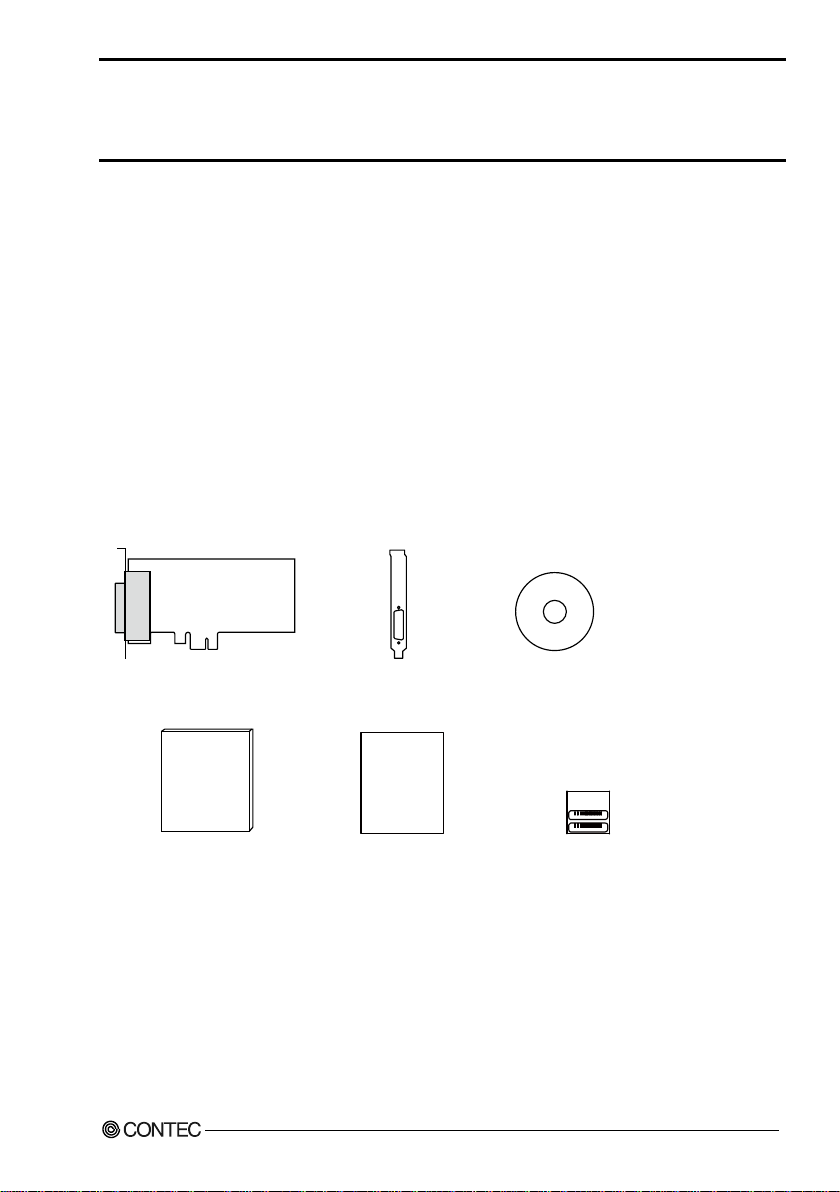
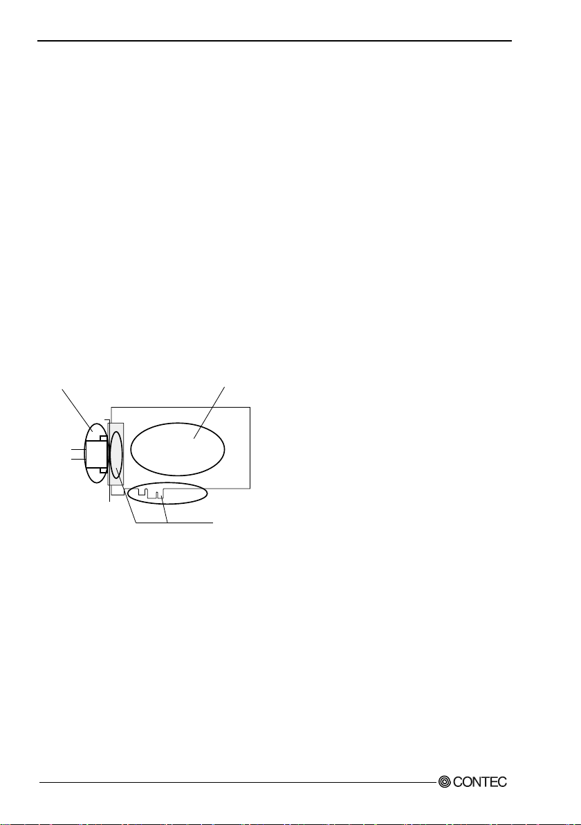
Check Your Package
Thank you for purchasing the CONTEC product.
The product consists of the items listed below.
Check, with the following list, that your package is complete. If you discover damaged or missing
items, contact your retailer.
Product Configuration List
- Board [DIO-1616B-LPE] …1
- Standard-sized bracket …1
- First step guide …1
- Disk *1 [API-PAC(W32)] …1
- Warranty Certificate …1
- Serial number label …1
*1 Driver software (API-PAC(W32)), User’s Guide (this guide)
DIO-1616B-LPE
i
Page 3

Copyright
Copyright 2015 CONTEC CO., LTD. ALL RIGHTS RESERVED.
No part of this document may be copied or reproduced in any form by any means without prior written
consent of CONTEC CO., LTD.
CONTEC CO., LTD. makes no commitment to update or keep current the information contained in
this document. The information in this document is subject to change without notice.
All relevant issues have been considered in the preparation of this document. Should you notice an
omission or any questionable item in this document, please feel free to notify CONTEC CO., LTD.
Regardless of the foregoing statement, CONTEC assumes no responsibility for any errors that may
appear in this document or for results obtained by the user as a result of using this product.
Trademarks
MS, Microsoft, Windows and Windows NT are trademarks of Microsoft Corporation. Other brand and
product names are trademarks of their respective holder.
DIO-1616B-LPE
ii
Page 4

Table of Contents
Check Your Package ................................................................................................................................... i
Copyright ..................................................................................................................................................... ii
Trademarks .................................................................................................................................................. ii
Table of Contents ....................................................................................................................................... iii
1. BEFORE USING THE PRODUCT 1
About the Board .......................................................................................................................................... 1
Features ................................................................................................................................................. 1
Support Software ................................................................................................................................. 3
Cable & Connector (Option) ............................................................................................................. 4
Accessories (Option) .......................................................................................................................... 4
Customer Support ....................................................................................................................................... 5
Web Site ............................................................................................................................................... 5
Limited Three-Years Warranty ................................................................................................................. 5
How to Obtain Service ............................................................................................................................... 5
Liability ........................................................................................................................................................ 5
Safety Precautions....................................................................................................................................... 6
Safety Information ............................................................................................................................... 6
Handling Precautions .......................................................................................................................... 7
Environment ......................................................................................................................................... 8
Inspection ............................................................................................................................................. 8
Storage .................................................................................................................................................. 8
Disposal ................................................................................................................................................ 8
2. SETUP 9
What is Setup?............................................................................................................................................. 9
Using the Board under Windows Using the Driver Library API-PAC(W32) .............................. 9
Using the Board under an OS Other than Windows ........................................................................ 9
Step 1 Installing the Software.................................................................................................................. 10
About the driver to be used ........................................................................................................... 10
Starting the Install Program.............................................................................................................. 11
Select API-DIO(WDM) .................................................................................................................... 12
Step 2 Setting the Hardware .................................................................................................................... 13
Replacing the Bracket ....................................................................................................................... 13
Parts of the Board and Factory Defaults ......................................................................................... 14
Setting the Board ID.......................................................................................................................... 14
Selecting Power Supply .................................................................................................................... 15
Plugging the Board ............................................................................................................................ 16
Step 3 Installing the Hardware ................................................................................................................ 17
Turning on the PC ............................................................................................................................. 17
DIO-1616B-LPE
iii
Page 5
Found New Hardware Wizard Setting ................................................................................................. 18
Step 4 Initializing the Software ............................................................................................................... 19
Step 5 Operation Checks .......................................................................................................................... 21
Check Method .................................................................................................................................... 21
Using the Diagnosis Program .......................................................................................................... 22
Setup Troubleshooting ............................................................................................................................. 25
Symptoms and Actions ..................................................................................................................... 25
3. EXTERNAL CONNECTION 27
How to connect the connectors ............................................................................................................... 27
Connector shape ................................................................................................................................ 27
Connector Pin Assignment ............................................................................................................... 28
Relationships between API-PAC(W32) Logical Ports/Bits and Connector Signal Pins ........... 29
Connecting Input Signals ......................................................................................................................... 30
Input Circuit ....................................................................................................................................... 30
Connecting a Switch ......................................................................................................................... 31
Connecting Output Signals ...................................................................................................................... 32
Output Circuit .................................................................................................................................... 32
Connection to the LED ..................................................................................................................... 33
Example of Connection to TTL Level Input .................................................................................. 33
Connecting the Sink Type Output and Sink Output Support Input ..................................................... 34
4. FUNCTION 35
Data I/O Function ..................................................................................................................................... 35
Data Input ........................................................................................................................................... 35
Data Output ........................................................................................................................................ 35
Monitoring Output Data ................................................................................................................... 35
Digital Filter .............................................................................................................................................. 36
Digital Filter Function Principle ...................................................................................................... 36
Set Digital Filter Time ...................................................................................................................... 37
Interrupt Control Function ....................................................................................................................... 38
Disabling/enabling Interrupts ........................................................................................................... 38
Selecting the Interrupt Edge ............................................................................................................. 38
Clearing the Interrupt Status and Interrupt Signal ......................................................................... 38
5. ABOUT SOFTWARE 39
Bundled Media Directory Structure........................................................................................................ 39
About Software for Windows .................................................................................................................. 40
Accessing the Help File .................................................................................................................... 40
Using Sample Programs ................................................................................................................... 41
Uninstalling the Driver Libraries ..................................................................................................... 42
About Software for Linux ........................................................................................................................ 43
DIO-1616B-LPE
iv
Page 6

Driver Software Install Procedure ................................................................................................... 43
Accessing the Help File .................................................................................................................... 44
Using Sample Programs.................................................................................................................... 44
Uninstalling the driver ...................................................................................................................... 44
6. ABOUT HARDWARE 45
For detailed technical information .......................................................................................................... 45
Hardware specification ............................................................................................................................. 45
Block Diagram .......................................................................................................................................... 47
Differences between DIO-1616B-LPE and PIO-16/16B(PCI)H, PIO-16/16B(LPCI)H, DIO-
1616B-PE ................................................................................................................................................... 48
DIO-1616B-LPE
v
Page 7

DIO-1616B-LPE
vi
Page 8

1. Before Using the Product
1. Before Using the Product
This chapter provides information you should know before using the product.
About the Board
This product is a PCI Express bus-compliant interface board that extends the digital signal I/O
functions of a PC.
This product is a 12 - 24VDC opto-coupler isolated type with opto-coupler isolated input 16ch and optocoupler isolated open-collector output 16ch. You can use all of the input signals as interrupt inputs.
Equipped with the power for opto-coupler operation (12VDC) supplied and the digital filter function
and output transistor protection circuit (surge voltage protection and overcurrent protection).
This product supports a Low Profile size slot and, if replaced with the supplied bracket, supports a
standard size slot, too.
Windows/Linux driver is bundled with this product.
Using the dedicated library VI-DAQ makes it possible to create each application for LabVIEW.
Features
Opto-coupler isolated input (supporting current sink output) and opto-coupler isolated open-collector output (current sink type)
This product has the opto-coupler isolated input 16ch (supporting current sink output) whose response
speed is 200sec and opto-coupler isolated open-collector output 16ch (current sink type).
Common terminal provided per 16ch, capable of supporting a different external power supply.
Supporting driver voltages of 12 - 24 VDC for I/O
Opto-coupler bus isolation
As the PCI Express bus (PC) is isolated from the input and output interfaces by opto-couplers, this
product has excellent noise performance.
Power for opto-coupler operation (12VDC 240mA) supplied internally
As the power to run the opto-couplers is supplied internally, no external power supply is required. The
use of jumpers allows you to decide whether you want to use the internal or external power supply for
every 16 points.
You can use all of the input signals as interrupt events.
You can use all of the input signals as interrupt events and also disable or enable the interrupt in bit
units and select the interrupt edge.
DIO-1616B-LPE
1
Page 9

1. Before Using the Product
Windows/Linux compatible driver libraries are attached.
Using the attached driver library API-PAC(W32) makes it possible to create applications of
Windows/Linux. In addition, a diagnostic program by which the operations of hardware can be
checked is provided.
This product has a digital filter to prevent input signals from carrying noise or a chattering.
This product has a digital filter to prevent input signals from carrying noise or a chattering. All input
terminals can be added a digital filter, and the setting can be performed by software.
Output circuits include zener diodes for surge voltage protection and overcurrent protection circuit.
Zener diodes are connected to the output circuits to protect against surge voltages. Similarly,
overcurrent protection circuits are fitted to each group of 8ch outputs.
Functions are compatible with PCI Express compatible board DIO-1616B-PE and PCI compatible board PIO-16/16B(PCI)H.
The functions same with PCI Express compatible board DIO-1616B-PE and PCI compatible board
PIO-16/16B(PCI)H are provided.
Functions and connectors are compatible with PCI compatible board PIO-16/16B(LPCI)H series.
The functions same with PCI compatible board PIO-16/16B(LPCI)H are provided.
In addition, as there is compatibility in terms of connector shape and pin assignments, it is easy to
migrate from the existing system.
LabVIEW is supported by a plug-in of dedicated library VI-DAQ.
Using the dedicated library VI-DAQ makes it possible to create each application for LabVIEW.
DIO-1616B-LPE
2
Page 10

1. Before Using the Product
Support Software
You should use CONTEC support software according to your purpose and development environment.
Windows version of digital I/O driver
[Stored on the bundled media driver library API-PAC(W32)]
The API-DIO(WDM) is the Windows version driver library software that provides products in the
form of Win32 API functions (DLL). Various sample programs such as Visual Basic and Visual C++,
etc and diagnostic program *1useful for checking operation is provided.
For more details on the supported OS, applicable language and how to download the updated version,
please visit the
CONTEC’s Web site ( http://www.contec.com/apipac/).
Linux version of digital I/O driver
[Stored on the bundled media driver library API-PAC(W32)]
The API-DIO(LNX) is the Linux version driver software which provides device drivers (modules) by
shared library and kernel version. Various sample programs of gcc are provided.
For more details on the supported OS, applicable language and how to download the updated version,
please visit the CONTEC’s Web site (http://www.contec.com/apipac/).
API-DIO(WDM)/API-DIO(98/PC)
API-DIO(LNX)
Data acquisition VI library for LabVIEW
the CONTEC web site.)
This is a VI library to use in National Instruments LabVIEW.
VI-DAQ is created with a function form similar to that of LabVIEW's Data Acquisition VI, allowing
you to use various devices without complicated settings.
See http://www.contec.com/vidaq/ for details and download of VI-DAQ.
(Available for downloading (free of charge) from
VI-DAQ
DIO-1616B-LPE
3
Page 11

1. Before Using the Product
Cable & Connector (Option)
Shield Cable with Two 50-Pin Mini-Ribbon Connector : PCB50PS-0.5P(0.5m)
: PCB50 PS-1.5P(1.5m)
: PCB50 PS-3P(3m)
: PCB50 PS-5P(5m)
Shield Cable with One 50-Pin Mini-Ribbon Connector : PCA50PS-0.5P(0.5m)
: PCA50PS-1.5P(1.5m)
: PCA50PS-3P(3m)
: PCA50PS-5P(5m)
Connection Conversion 0.5m Shield Cable (50-Pin Ribbon->37-Pin D-SUB)
: PCE50/37PS-0.5P(0.5m)
Accessories (Option)
Screw Terminal Unit(M3 terminal block, 50 points) : EPD-50A *1 *2
Screw Terminal Unit(M3 terminal block, 37 points) : EPD-37A *1 *3
Screw Terminal Unit(M3.5 terminal block, 37 points) : EPD-37 *3
Termination Panel (M3) : DTP-3A *3
Termination Panel : DTP-4C *3
Signal Monitor for Digital I/O : CM-32L *3
*1 "Spring-up" type terminal is used to prevent terminal screws from falling off.
*2 PCB50PS-*P optional cable is required separately.
*3 PCE50/37PS-0.5P and PCB37 P or PCB37PS optional cable is required separately.
* Check the CONTEC’s Web site for more information on these options.
DIO-1616B-LPE
4
Page 12

1. Before Using the Product
Customer Support
CONTEC provides the following support services for you to use CONTEC products more efficiently
and comfortably.
Web Site
Japanese http://www.contec.co.jp/
English http://www.contec.com/
Chinese http://www.contec.com.cn/
Latest product information
CONTEC provides up-to-date information on products.
CONTEC also provides product manuals and various technical documents in the PDF.
Free download
You can download updated driver software and differential files as well as sample programs available
in several languages.
Note! For product information
Contact your retailer if you have any technical question about a CONTEC product or need its price,
delivery time, or estimate information.
Limited Three-Years Warranty
CONTEC products are warranted by CONTEC CO., LTD. to be free from defects in material and
workmanship for up to three years from the date of purchase by the original purchaser.
Repair will be free of charge only when this device is returned freight prepaid with a copy of the
original invoice and a Return Merchandise Authorization to the distributor or the CONTEC group
office, from which it was purchased.
This warranty is not applicable for scratches or normal wear, but only for the electronic circuitry and
original products. The warranty is not applicable if the device has been tampered with or damaged
through abuse, mistreatment, neglect, or unreasonable use, or if the original invoice is not included, in
which case repairs will be considered beyond the warranty policy.
How to Obtain Service
For replacement or repair, return the device freight prepaid, with a copy of the original invoice. Please
obtain a Return Merchandise Authorization number (RMA) from the CONTEC group office where
you purchased before returning any product.
* No product will be accepted by CONTEC group without the RMA number.
Liability
The obligation of the warrantor is solely to repair or replace the product. In no event will the
warrantor be liable for any incidental or consequential damages due to such defect or consequences
that arise from inexperienced usage, misuse, or malfunction of this device.
DIO-1616B-LPE
5
Page 13
1. Before Using the Product
DANGER indicates an imminently hazardous situation which, if not avoided, will
result in death or serious injury.
WARNING indicates a potentially hazardous situation which, if not avoided, could
result in death or serious injury.
CAUTION indicates a potentially hazardous situation which, if not avoided, may
result in minor or moderate injury or in property damage.
DANGER
WARNING
CAUTION
Safety Precautions
Understand the following definitions and precautions to use the product safely.
Safety Information
This document provides safety information using the following symbols to prevent accidents resulting
in injury or death and the destruction of equipment and resources. Understand the meanings of these
labels to operate the equipment safely.
DIO-1616B-LPE
6
Page 14
1. Before Using the Product
DANGER
CAUTION
Handling Precautions
Do not use the product where it is exposed to flammable or corrosive gas. Doing so may result in
an explosion, fire, electric shock, or failure.
- There are switches and jumpers on this product that need to be set in advance.
Be sure to check these before installing to the expansion slot.
- Only set the switches and jumpers on this product to the specified settings.
Otherwise, this product may malfunction, overheat, or cause a failure.
- Do not strike or bend this product.
Otherwise, this product may malfunction, overheat, cause a failure or breakage.
- Do not touch this product's metal plated terminals (edge connector) with your hands.
Otherwise, this product may malfunction, overheat, or cause a failure.
If the terminals are touched by someone's hands, clean the terminals with industrial alcohol.
- Do not install or remove this product to or from the expansion slot while the computer's power or
expansion unit is turned on.
Otherwise, this product may malfunction, overheat, or cause a failure.
Be sure that the personal computer power is turned off.
- Make sure that your PC or expansion unit can supply ample power to all the products installed.
Insufficiently energized products could malfunction, overheat, or cause a failure.
- The specifications of this product are subject to change without notice for enhancement and
quality improvement.
Even when using this product continuously, be sure to read the user’s guide and understand the
contents.
- Do not modify this product. CONTEC will bear no responsibility for any problems, etc., resulting
from modifying this product.
- Regardless of the foregoing statements, CONTEC is not liable for any damages whatsoever
(including damages for loss of business profits) arising out of the use or inability to use this
CONTEC product or the information contained herein.
DIO-1616B-LPE
7
Page 15
1. Before Using the Product
- Check that the board has
- Che ck that the bus co nnector
- The gold-plated leads of
~
~
no dust or foreign matter adhering.
of the board and its cable have
been plugged c orrectly.
the bus connector.
Environment
Use this product in the following environment. If used in an unauthorized environment, the product
may overheat, malfunction, or cause a failure.
Operating temperature
0 - 50C
Operating Humidity
10 - 90%RH (No condensation)
Corrosive gases
None
Floating dust particles
Not to be excessive
Inspection
Inspect the product periodically as follows to use it safely.
Storage
When storing this product, keep it in its original packing form.
(1) Put the product in the storage bag.
(2) Wrap it in the packing material, then put it in the box.
(3) Store the package at room temperature at a place free from direct sunlight, moisture, shock,
vibration, magnetism, and static electricity.
Disposal
When disposing of the product, follow the disposal procedures stipulated under the relevant laws and
municipal ordinances.
DIO-1616B-LPE
8
Page 16

2. Setup
2. Setup
This chapter explains how to set up the board.
What is Setup?
Setup means a series of steps to take before the product can be used.
Different steps are required for software and hardware.
The setup procedure varies with the OS and software used.
Using the Board under Windows
Using the Driver Library API-PAC(W32)
This section describes the setup procedure to be performed before you can start developing application
programs for the board using the bundled media “Driver Library API -PAC(W32)”.
Taking the following steps sets up the software and hardware. You can use the diagnosis program
later to check whether the software and hardware function normally.
Step 1 Installing the Software
Step 2 Setting the Hardware
Step 3 Installing the Hardware
Step 4 Initializing the Software
Step 5 Operation Checks
If Setu p fails to be performed normally, see the “Setup Troubleshooting” section at the end of this
chapter.
Using the Board under an OS Other than Windows
For using the board under an OS other than Windows, see the following parts of this user’s guide.
This chapter Step 2 Setting the Hardware
Chapter 3 External Connection
Chapter 6 About Hardware
DIO-1616B-LPE
9
Page 17

2. Setup
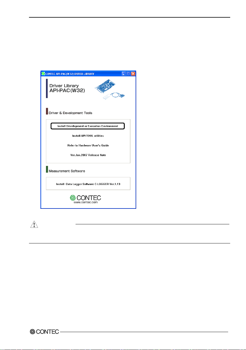
Step 1 Installing the Software
This section describes how to install the Driver libraries.
Before installing the hardware on your PC, install the Driver libraries from the bundled
API-PAC(W32).
Although some user interfaces are different depending on the OS used, the basic procedure is the
same.
About the driver to be used
Two Analog I/O drivers are available : API-DIO(WDM) and API-DIO(98/PC).
API-DIO(WDM) is a driver to perform analog I/O under Windows.
When this product is used, digital input/output high performance driver "API-DIO(WDM)" is used.
If you use this product with digital input and output high-performance driver API-DIO (WDM).
If API-DIO (98 / PC) using existing systems continue to use API-DIO (98 / PC).
Please note that the API-DIO 98 (PC) does not support Windows 8 or later, and the 64-bit OS.
Use the API-DIO(98/PC)
If you are installing from media attachments, select "all" from the "Installer" later in this chapter and
starts the execution environment and development environment packages installer
Please see the Help folder in the installed hardware installation instructions please see reference in
help media attachments or downloaded from
Furthermore, that applies to the default step 4 software described below, see config.chm folder
installed execution environment
CONTEC’s Web site
development environment.
DIO-1616B-LPE
10
Page 18
2. Setup
CAUTION
Starting the Install Program
(1)
Load the bundled media [API-PAC(W32)] on your PC.
(2)
The API-PAC(W32) Installer window appears automatically.
If the panel does not appear, run (drive letter):\AUTORUN.exe.
(3)
Click on the [Install Development or Execution Environment] button.
* When using the Windows Vista, driver is automatically installed.
Before installing the software in Windows Vista, Windows XP, Server 2003 and 2000, log in as a
user with administrator privileges.
DIO-1616B-LPE
11
Page 19

2. Setup
Select API-DIO(WDM)
Selecting API-DIO(WDM)
(1)
The following dialog box appears to se lect “Driver to install” and “Install option”, “Usage of
driver library”.
(2)
Select the "Advanced Digital I/O driver".
(3)
Click on the [Install] button.
* Clicking the [API-DIO] button under the “Detail” displays detailed infor mation about API-
DIO(WDM) and API-DIO(98/PC).
Run the installation
(1)
Complete the installation by following the instructions on the screen.
(2)
The Readme file appears when the installation is complete.
DIO-1616B-LPE
12
Page 20

2. Setup
Use a flathead screwdriver or hexagonal
spanner to undo and tighten the screws.
- Remove the screws and replace it
with the Standard size bracket.
Screw
Standard size bracket
Low Profile size bracket
Step 2 Setting the Hardware
This section describes how to set the board and plug it on your PC.
The board has some switches to be preset.
Check the on-board switches before plugging the board into an extension slot.
The board can be set up even with the factory defaults untouched. You can change board settings
later.
Replacing the Bracket
This board is shipped with a Low Profile size bracket mounted. To plug the board into a standard size
slot, replace the bracket with the bundled standard size bracket. The replacing method is as follows :
Figure 2.1. Replacing the Bracket
DIO-1616B-LPE
13
Page 21

2. Setup
0
1
2
3
4
5
6
7
9
A
B
C
D
E
F
8
- Power supply setting
jumper
(JP1-JP4)
JP1-4
1 2 3
DIO-1616B-LPE
SW1
BOARD ID
- Board ID setting switch
SW1
BOARD ID
- Interface connector
(CN1)
(Board ID = 0)
Factory setting:
BOARD ID
SW1
0
1
2
3
4
5
6
7
9
A
B
C
D
E
F
8
Parts of the Board and Factory Defaults
Figure 2.2. shows the names of major parts on the board.
Note that the switch setting shown below is the factory default.
Figure 2.2. Component Locations
Setting the Board ID
If you install two or more boards on one personal computer, assign a different ID value to each of the
boards to distinguish them.
The board IDs can be set from 0 to Fh to identify up to sixteen boards.
If only one board is used, the original factory setting (Board ID = 0) should be used.
Setting Procedure
To set the board ID, use the rotary switch on the board. Turn the SW1 knob to set the board ID as
shown below.
Figure 2.3. Board ID Settings (SW1)
DIO-1616B-LPE
14
Page 22

2. Setup
CAUTION
Use internal power*
+0 port (Input)
+1 port (Input)
+2 port (output)
+3 port (output)
JP1 JP3
JP2
JP4
JP2
JP4
*Factory setting
Notes:These jumpers must be set in pairs.
Ports +0 and +1 serve as inputs and ports +2 and +3 serve as outputs.
JP1 JP3
1 2 3 1 2 3
1 2 3 1 2 3
1 2 3 1 2 3
1 2 3 1 2 3
Use external power
Selecting Power Supply
This board equips an on board isolated power supply (12VDC, 240mA) for driving opto-isolation
circuits. You can select to use this internal power supply or use an external power supply for driving
the opto-isolation circuits in unit of two ports (16channels) per common.
- When the internal power supply is used, the input section of this board consumes up to 40mA
current maximum and the output channel switching section consumes up to 30mA current
maximum. Note, in this case, that the board can supply the following output current :
DIO-1616B-LPE: 170 mA
- The both internal and external supply must not be used simultaneously. Or the supply will be
broken down.
Setting method
Jumpers JP1 - JP4 on the board are used to select the internal or external power supply.
Figure 2.4. Power supply setting for driving the opto-coupler
DIO-1616B-LPE
15
Page 23

2. Setup
CAUTION
Plugging the Board
(1) Before plugging the board, shut down the system, unplug the power code of your PC.
(2) Remove the cover from the PC so that the board can be mounted.
(3) Plug the board into an extension slot.
(4) Attach the board bracket to the PC.
(5) Put the cover back into place.
- Do not touch the board's metal plated terminals (edge connector) with your hands.
Otherwise, the board may malfunction, overheat, or cause a failure.
If the terminals are touched by someone's hands, clean the terminals with industrial alcohol.
- Do not install or remove the board to or from the slot while the computer's or extension unit’s power
is turned on.
Otherwise, the board may malfunction, overheat, or cause a failure.
Be sure that the personal computer power is turned off.
- Make sure that your PC or extension unit can supply ample power to all the boards installed.
Insufficiently energized boards could malfunction, overheat, or cause a failure.
DIO-1616B-LPE
16
Page 24

2. Setup
CAUTION
Step 3 Installing the Hardware
For using an expansion board under Windows, you have to let the OS detect the I/O addresses and
interrupt level to be used by the board. The process is referred to as installing the hardware.
In the case of using two or more boards, make sure you install one by one with the Add New Hardware
Wizard.
Turning on the PC
Turn on the power to your PC.
- The board cannot be properly installed unless the resources (I/O addresses and interrupt level) for
the board can be allocated. Before attempting to install the board, first determine what PC
resources are free to use.
- The resources used by each board do not depend on the location of the PCI Express bus slot or the
board itself. If you remove two or more boards that have already been installed and then remount
one of them on the computer, it is unknown that which one of the sets of resources previously
assigned to the two boards is assigned to the remounted board. In this case, you must check the
resource settings.
DIO-1616B-LPE
17
Page 25

2. Setup
Found New Hardware Wizard Setting
Depending on the OS that you use, the installation process may start automatically without starting the
wizard. In this situation, proceed to "Step 4 Initializing the Software".
Performing installations on various operating systems
Help files containing the methods to follow in performing installations on different Windows
operating systems are included on the bundled media, so refer to the files in the following folder.
¥Help¥Hwinst¥Eng¥ApiTool.chm
(1) The “ Found New Hardware Wizard” will be started.
Select “No, not this time” and then click the “Next” button.
(2) When the model name of hardware is displayed, select “Install the software automatically
[Recommended]” and then click on the “Next” button.
The device is automatically installed, and processing is completed.
You have now finished installing the initial setting of Hardware.
DIO-1616B-LPE
18
Page 26

2. Setup
CAUTION
* The name of the board
you have just added is displayed.
DIO-1616B-PE DIO-1616B-LPE "DIO000“
Step 4 Initializing the Software
The driver library requires the initial setting to recognize the execution environment. It is called the
initialization of the Driver library.
This software is initialized automatically during hardware installation. Therefore, if you want to use it
with its initial settings, you can skip the setting procedure described in Step 4. To change the device
name, follow the setting procedure shown below.
Setting the device name
(1) Run Device Manager. From [My Computer] - [Control Panel], select [System] and then select the
[Device Manager] tab.
(You can also open Device Manager by right clicking on My Computer and selecting Properties.)
When you install this product, the displayed board name is "DIO-1616B-PE DIO-1616B-LPE".
(2) The installed hardware appears under the CONTEC Devices node. Open the CONTEC Devices
node and select the device you want to setup (the device name should appear highlighted). Click
[Properties].
DIO-1616B-LPE
19
Page 27

2. Setup
CAUTION
* The name of the board
you have just added is displayed.
DIO-1616B-PE DIO-1616B-LPE
(3) The property page for the device opens.
Enter the device name in the common settings tab page and then click [OK].
The device name you set here is used later when programming.
* The initial device name that appears is a default value. You can use this default name if you wish.
* Make sure that you do not use the same name for more than one device.
When you install this product, the displayed board name is "DIO-1616B-PE DIO-1616B-LPE".
You have now finished installing the initial setting of Software.
DIO-1616B-LPE
20
Page 28

2. Setup
CM-32L
Option cable
PCE50/37PS-0.5P and PCB37P or PCB37PS
Connector
Step 5 Operation Checks
You must make sure that the board and driver software operate normally. By taking this step, you can
make sure that the board has been set up correctly.
Check Method
Connect the board to a remote device to test the input/output and check the execution environment.
The Check Mate (CM-32L) comes in handy when you check digital I/O boards.
Check the board with the factor defaults untouched.
Connection diagram
To connect a device other than the Check Mate, see Chapter 3 “External Connection”.
DIO-1616B-LPE
21
Page 29

2. Setup
Using the Diagnosis Program
Starting the Diagnosis Program Open the “Properties” page of the device that was used for the software initialization, and press the
[Diagnosis] button.
DIO-1616B-LPE
22
Page 30

2. Setup
CAUTION
* The name of the board
you have just added is displayed.
DIO-1616B-LPE
Checking Digital Inputs and Outputs
The main panel of the Diagnosis Program appears.
You can check the current operation states of the board in the following boxes:
“Input Port” : Displays input values bit by bit at fixed time intervals.
“Output Port” : Mouse operation allows the data to output or display.
“Interrupt” : Displays the number of interrupts detected bit by bit.
When you install this product, the displayed board name is "DIO-1616B-LPE".
To use the function execution time measurement feature, click on the [Measurement Time] button.
Enter the I/O start port and the number of ports, then press the measurement button. The time for each
execution of a function will be measured.
DIO-1616B-LPE
23
Page 31

2. Setup
CAUTION
CAUTION
* The name of the board
you have just added is displayed.
DIO-1616B-LPE
Diagnosis Report
(1) Clicking on the [Show Diagnosis Report] button displays detailed data such as board settings and
the diagnosis results while saving them in text format.
The Diagnosis Program performs “board presence/absence check”, “driver file test”, “board
setting test”, and so on.
Before executing diagnosis report output, unplug the cable from the board.
When you install this product, the displayed board name is "DIO-1616B-LPE".
DIO-1616B-LPE
24
Page 32

2. Setup
CAUTION
* The name of the board
you have just added is displayed.
DIO-1616B-LPE
(2) A diagnosis report is displayed as shown below.
When you install this product, the displayed board name is "DIO-1616B-LPE".
Setup Troubleshooting
Symptoms and Actions
The board works with the Diagnosis Program but not with an application.
The Diagnosis Program is coded with API-DIO(WDM) functions. As long as the board operates with
the Diagnosis Program, it is to operate with other applications as well. In such cases, review your
program while paying attention to the following points:
- Check the return values of functions.
- Refer to the source code of sample program.
Refer to the “Troubleshooting” in API-TOOL(WDM) HELP (APITOOL.chm)
DIO-1616B-LPE
25
Page 33

2. Setup
DIO-1616B-LPE
26
Page 34

3. External Connection
CN1
- Connector used
50-Pin Mini-Ribbon connector
10250-52A2JL[mfd.by 3M]
- Applilcable connector
10150-6000EL[mfd. by 3M]
Interface connector (CN1)
3. External Connection
This chapter describes the interface connectors on the board and the external I/O circuits.
Check the information available here when connecting an external device.
How to connect the connectors
Connector shape
To connect an external device to this product, plug the cable from the device into the interface
connector (CN1) shown below.
* Please refer to chapter 1 for more information on the su pported cable an d accessories.
Figure 3.1. Interface Connector and Applicable Cable Connector
DIO-1616B-LPE
27
Page 35

3. External Connection
Common minus pin
for +2/+3 output
ON 2/3
50 25
ON 2/3
Common minus pin for
+2/+3 out put ports
ON 2/3
49
24
ON 2/3
+2 port
(output)
O-20
48
23
O-30
+3 port
(output)
O-21
47
22
O-31
O-22
46
21
O-32
O-23
45
20
O-33
O-24
44
19
O-34
O-25
43
18
O-35
O-26
42
17
O-36
O-27
41
16
O-37
Common plus pin for
+2/+3 out put ports
OP 2/3
40
15
OP 2/3
Common plus pin for
+2/+3 out put ports
OP 2/3
39
14
OP 2/3
N.C.
38
13
N.C.
Common minus pin
for +0/+1 input ports
IN 0/1
37
12
IN 0/1
Common minus pin for
+0/+1 inp ut ports
IN 0/1
36
11
IN 0/1
+0 port
(input)
I-00
35
10
I-10
+1 port
(input)
I-01
34
9
I-11
I-02
33
8
I-12
I-03
32
7
I-13
I-04
31
6
I-14
I-05
30
5
I-15
I-06
29
4
I-16
I-07
28
3
I-17
Common plus pin for
+0/+1 inp ut ports
IP 0/1
27 2 IP 0/1
Common plus pin for
+0/+1 inp ut ports
IP 0/1
26 1 IP 0/1
I-00 - I-17
16 input signal pins. Con nect output signals from t he exte rnal device to these pins.
O20 - O37
16 output signal pins. Connect t hese pins to the input signal pins of the e xternal device.
IP 0/1
When the external power s upply is selecte d, its positive side is connected to this pin.
When the internal power s upply is used, th is pin outputs power at +12 V. T hese pins are
common t o 16 input signal pins.
OP 2/3
When the external power s upply is selecte d, its positive side is c onnected to this pin.
When the internal power s upply is used, this pin outputs p ower at +12 V. These pins are
common t o 16 out put signal pins.
IN 0/1
When the external power s upply is selecte d, its negative s ide is connected to this pin.
When the internal power s upply is selecte d, this pin serves as the ground. These p ins are
common t o 16 input signal pins.
ON 2/3
When the external power s upply is selecte d, its negative s ide is connected to this pin.
When the internal power s upply is s electe d, this pin serves as the ground. These pins are
common t o 16 out put signal pins.
N.C.
This pin is left unconnecte d.
50 25
26 1
Connector Pin Assignment
Pin Assignments of Interface Connector
Figure 3.2. Pin Assignments of Interface Connector
DIO-1616B-LPE
28
Page 36

3. External Connection
D7
D6
D5
D4
D3
D2
D1
D0
Input log ical port 0
I-07
[7]
I-06
[6]
I-05
[5]
I-04
[4]
I-03
[3]
I-02
[2]
I-01
[1]
I-00
[0]
Input log ical port 1
I-17
[15]
I-16
[14]
I-15
[13]
I-14
[12]
I-13
[11]
I-12
[10]
I-11
[9]
I-10
[8]
D7
D6
D5
D4
D3
D2
D1
D0
Output logical port 0
O-27
[7]
O-26
[6]
O-25
[5]
O-24
[4]
O-23
[3]
O-22
[2]
O-21
[1]
O-20
[0]
Output logical port 1
O-37
[15]
O-36
[14]
O-35
[13]
O-34
[12]
O-33
[11]
O-32
[10]
O-31
[9]
O-30
[8]
Notes :
I-xx represents t he input signal. O-xx represents the output
signal.
[xx] represents t he logica l bit.
CAUTION
Relationships between API-PAC(W32) Logical Ports/Bits and Connector Signal Pins
The following table lists the relationships between the connector signal pins and the logical port/bit
numbers used for I/O functions when applications are written with API -PAC(W32).
The logical port and logical bit numbers are virtual port and bit numbers that enable programming
independent of board I/O addresses or board types.
For details, refer to API-DIO HELP available after installing API-PAC(W32).
Table 3.1. Logical Ports, Logical Bits, and Connector Signal Pins
DIO-1616B-LPE
29
Page 37

3. External Connection
CAUTION
Connecting Input Signals
Connect the input signals to a device which can be current-driven, such as a switch or transistor output
device.
The connection requires an external power supply to feed currents.
The board inputs the ON/OFF state of the current-driven device as a digital value.
Input Circuit
* I-xx represents the input pin.
Figure 3.3. Input Circuit
The input circuits of interface is illustrated in Figure 3.3.
The signal inputs are isolated by opto-couplers (ready to accept current sinking output signals). The
board therefore requires an external power supply to drive the inputs. The power requirement for each
input pin is about 5.1mA at 24VDC (about 2.6mA at 12VDC).
Please refer to Selecting Power Supply, and choose the proper supply by jumps.
DIO-1616B-LPE
30
Page 38

3. External Connection
Board side
Switch
I-00 (CN1 : 35pin)
Input minus common (CN1 - 36pin)
Connecting a Switch
When the switch is ON, the corres ponding bit contains 1. When the switch is OFF, by contrast , the bit contai ns 0.
Figure 3.4. An Example to use Input I-00
DIO-1616B-LPE
31
Page 39

3. External Connection
Connecting Output Signals
Connect the output signals to a current-driven controlled device such as a relay or LED.
The connection requires an external power supply to feed currents.
The board controls turning on/off the current-driven controlled device using a digital value.
Output Circuit
* O-xx represents the output pin.
Figure 3.5. Output Circuit
The output circuits of interface is illustrated in Figure 3.5. The signal output section is an optocoupler isolated, open-collector output (current sink type). Driving the output section requires the onboard internal power supply or the external power supply.
The rated output current per channel is 100mA at maximum.
The output section can also be connected to a TTL level input as it uses a low-saturated transistor for
output. The residual voltage (low-level voltage) between the collector and emitter with the output on
is 0.5V or less at an output current within 50mA or at most 1.0V at an output current within 100mA.
A zener diode is connected to the output transistor for protection from surge voltages. A overcurrent
protection circuit is provided for every 8 output transistors.
DIO-1616B-LPE
32
Page 40

3. External Connection
CAUTION
Board
Output plus common (CN1 : 39pin)
O-20 (CN1 : 48pin)
5.1kΩ
External
powwer supply
12 - 24VDC
Output plus common
Output
Output minus common
TTL level input
Input board
GND
VCC
2k
- +
When the PC is turned on, all output are reset to OFF.
Please refer to Selecting Power Supply, and choose the proper supply by jumps.
Connection to the LED
When "1" is output to a re levant bi t, the corresponding LED comes on. When "0" is output to the bit, in contrast , the LED goes out.
Figure 3.6. An Example to use Output O-20
Example of Connection to TTL Level Input
Figure 3.7. Connection Example of Output and TTL level Input Signal
DIO-1616B-LPE
33
Page 41

3. External Connection
External
power supply
12 - 24VDC
Output plus common
Output (sink type)
Output minus common
Input board
Output board
Input plus common
Input (Compatible with sink output)
-
+
Connecting the Sink Type Output and Sink Output Support Input
The following example shows a connection between a sink type output (output board) and a sink
output support input (input board). Refer to this connection example when you connect such boards to
each other.
Figure 3.8. Example of Connecting the Sink Type Output and Sink Output Support Input
DIO-1616B-LPE
34
Page 42

4. Function
CAUTION
4. Function
This section describes the features of the board.
Each function described here can be easily set and executed by using the bundled API function library.
For details, refer to API-DIO HELP available after installation.
Data I/O Function
Data Input
When input data is “ON”, “1” is input to the relevant bit.
When the input data is “OFF”, in contrast, “0” is input to the relevant bit
Data Output
When “1” is output to the relevant bit, the corresponding transistor is set to “ON”.
When “0” is output to the relevant bit, in contrast, the corresponding transistor is set to “OFF”.
When the PC is turned on, all output are reset to 0 (OFF).
Monitoring Output Data
The DIO-1616B-LPE can read the state of the data currently being output without affecting the output
data.
DIO-1616B-LPE
35
Page 43

4. Function
Input Signal
Filter Setting Time
Invalid
Valid
Input to PC
Input Signal
Digital Filter
Input to PC
Digital Filter
Using this feature, the DIO-1616B-LPE can apply a digital filter to every input pin, thereby preventing
the input signal from being affected by noise or chattering.
Digital Filter Function Principle
The digital filter checks the input signal level during the sampling time of the clock signal. When the
signal level remains the same for the digital filter set time, the digital filter recognizes that signal as
the input signal and changes the signal level of the PC
If the signal level changes at a frequency shorter than the set time, therefore, the level change is
ignored.
Figure 4.1. Digital Filter Function Principle
36
DIO-1616B-LPE
Page 44

4. Function
Setting Data
(n)
Digital Filter
Time
Setting D ata
(n)
Digital Filter
Time
Setting D ata
(n)
Digital Filter
Time
0 (00h)
The filter function
is not use d.
7 (07h)
16sec
14 (0Eh)
2.048msec
1 (01h)
0.25sec
8 (08h)
32sec
15 (0Fh)
4.096msec
2 (02h)
0.5sec
9 (09h)
64sec
16 (10h)
8.192msec
3 (03h)
1sec
10 (0Ah)
128sec
17 (11h)
16.384msec
4 (04h)
2sec
11 (0Bh)
256sec
18 (12h)
32.768msec
5 (05h)
4sec
12 (0Ch)
512sec
19 (13h)
65.536msec
6 (06h)
8sec
13 (0Dh)
1.024msec
20 (14h)
131.072msec
CAUTION
Set Digital Filter Time
Set the digital filter time to 0 - 20 (14h).
Setting the digital filter time to 0 disables digital filtering. It is set to 0 when the power is turned on .
Figure 4.2 shows the relationships between digital filter time settings and the actual digital filter times.
Digital Filter Time[sec.] = 2n / (8 x 10⁶)
n: = setting data(0 - 20)
Figure 4.2. Digital Filter Time and Setting Data
- If you set the digital filter time, the filter applies to all input pins. You cannot apply the filter only
to a specific filter.
- Do not set Setting Data to a value outside the above range as doing so can cause the board to
malfunction.
DIO-1616B-LPE
37
Page 45

4. Function
CAUTION
CAUTION
CAUTION
Interrupt Control Function
The DIO-1616B-LPE can use all of the input signals as interrupt request signals.
This product can generate an interrupt request signal to the PC when the input signal change from
High to Low or from Low to High.
When the digital filter (described above) is used, interrupt requests are generated by input signals that
have passed through the filter.
Disabling/enabling Interrupts
Interrupt mask bits can be used to disable or enable the individual bits for interruptions.
Once a certain bit has been interrupt-disabled, no interrupt occurs even when the corresponding input
signal changes its level.
To let interrupts occur, enable the corresponding interrupt mask bit for interruptions.
All of the interrupt mask bits are interrupt-disabled when the power is turned on.
Selecting the Interrupt Edge
Interrupt edge select bits can be used to set the input logic for interruption bit by bit.
If you set an interrupt edge select bit to 0, an interrupt occurs when the input value to the
corresponding bit changes from 0 to 1 (at the fall of the input signal from High to Low).
If you set an interrupt edge select bit to 1, an interrupt occurs when the input value to the
corresponding bit changes from 1 to 0 (at the rise of the input signal from Low to High).
When the power is turned on, all of the interrupt edge select bits are set to 0 so that an interrupt
occurs when the input value changes from 0 to 1 (at the fall of the input signal from High to Low).
Clearing the Interrupt Status and Interrupt Signal
Interrupt status bits are used to identify the input signal bit being used for requesting an interrupt.
When an interrupt status is input, the interrupt request signal and the interrupt status are cleared
automatically.
- All of the interrupt status bits are set to 0 when the power is turned on.
- If an interrupt mask bit has been set to disable interrupts, the interrupt status bit is not set even
when the input signal changes its level.
DIO-1616B-LPE
38
Page 46

5. About Software
5. About Software
Bundled Media Directory Structure
\
|– Autorun.exe Installer Main Window
| Readmej.html Version information on each API-TOOL (Japanese)
| Readmeu.html Version information on each API-TOOL (English)
.
.
|–––APIPAC Each installer
| |––AIO
| | |––DISK1
| | |––DISK2
| | |––……
| | |––DISKN
| |––AioWdm
| |––CNT
| |––DIO
| |––……
.
.
| ––HELP HELP file
| |––Aio
| |––Cnt
| |––……
.
.
| ––INF Each INF file for OS
| |––WDM
| |––Win2000
| |––Win95
.
.
|––linux Linux driver file
| |––cnt
| |––dio
| |––……
.
.
| ––Readme Readme file for each driver
.
.
| ––Release Driver file on each API-TOOL
| |––API_NT (For creation of a user-specific install program)
| |––API_W95
.
.
| ––UsersGuide Hardware User's Guide(PDF files)
DIO-1616B-LPE
39
Page 47

5. About Software
About Software for Windows
The bundled media “Driver Library Package API-PAC(W32)” contains the functions that provide the
following features:
- Digital input/output of specified ports
- Hardware digital input/output of specified bits
- Hardware digital filtering that prevents chattering
For deta ils, refer to the help file. The help file provides various items of information such a s “Using
procedure” and “Function Reference”. Use them for program development.
Accessing the Help File
(1) Click on the [Start] button on the Windows taskbar.
(2) Using the “CONTEC API-PAC(W32) ”, from the Start Menu , select “Programs” – “CONT EC
API-PAC(W32)” - “API-DIO(WDM)” - “API-DIO(WDM) HELP” to display help informa tion.
DIO-1616B-LPE
40
Page 48

5. About Software
Using Sample Programs
Sample programs have been prepared for specific basic applications.
For the API-DIO(WDM), The sample programs are stored in
¥Program Files¥CONTEC¥API-PAC(W32) ¥DIOWDM¥Sample
Use these sample programs as references for program development and operation check.
* When the installation folder is changed, the folder of the sample program is different.
Running a Sample Program
(1) Click on the [Start] button on the Windows taskbar.
(2) For the API-DIO(WDM), from the Start Menu, select “Programs” – “CONTEC API -PAC(W32)”
– “API-DIO(WDM)” – “SAMPLE…”.
(3) A sample program is invoked.
Sample list
Simple I/O : Executes digital I/O processing of the specified port.
Multiple port/bit I/O ports/bits : Simultaneously executes digital I/O processing of multiple
Monitoring Trigger : Monitors rising-edge/falling-edge triggers.
Interrupt : Executes interrupt processing of the specified board.
DIO-1616B-LPE
41
Page 49

5. About Software
Uninstalling the Driver Libraries
< Uninstalling the device driver >
Run Device Manager. From [My Computer] - [Control Panel], select [System] and then select the
[Device Manager] tab.
(You can also open Device Manager by right clicking on My Computer and selecting Properties.)
Select [Windows Driver Package - CONTEC (****)], and then click [Change/Remove].
* "***" contains the driver category name (caio, ccnt, cdio, csmc, etc.).
< Uninstall the development environment >
Use [My Computer] - [Control Panel] - [Programs and Features] to uninstall the development
environment.
In case of API-***(WDM), select [CONTEC API-***(WDM) VerX.XX (Develop)] and then click
[Uninstall].
* "***" contains the driver category name (AIO, CNT, DIO, SMC, etc.).
DIO-1616B-LPE
42
Page 50

5. About Software
About Software for Linux
The Linux version of digital I/O function driver, API-DIO(LNX), provides functions that execute the
following features:
- Digital input/output of specified ports
- Digital input/output of specified bits
- Hardware digital filtering that prevents chattering
For details, refer to the help file. The help file provides various items of information such as
“Function Reference”, “Sample Programs”, and “FAQs”. Use them for program development and
troubleshooting.
Driver Software Install Procedure
The Linux version for digital I/O driver, API-DIO(LNX), is supplied as a compressed file
/linux/dio/cdioXXX.tgz on the bundled API-PAC(W32). (Note: XXX represents the driver version.)
Mount the bundled media as shown below, copy the file to an arbitrary directory, and decompress the
file to install the driver.
For details on using the driver, refer to readme.txt and the help file in HTML format extracted by
installation.
To install the driver, log in as a superuser.
Decompression and setup procedure
# cd
# mount /dev/cdrom /mnt/cdrom Mount the bundled media.
# cp /mnt/cdrom/linux/dio/cdioXXX.tgz ./ Copy the compressed file.
# tar xvfz cdioXXX.tgz Decompress the compressed file.
................
# cd contec/cdio
# make
Compile the file.
................
# make install Install.
................
# cd config
# ./config Set up the board to be used.
..... Set as follows.........
# ./contec_dio_start.sh Start the driver.
# cd
DIO-1616B-LPE
43
Page 51

5. About Software
Accessing the Help File
(1) Invoke a web browser in your X-Window environment.
(2) In the browser, open diohelp.htm in the the contec/cdio/help directory.
Using Sample Programs
Sample programs have been prepared for specific basic applications.
Sample programs for each language are contained in the contec/cdio/samples directory. For compiling
them, refer to the manual for the desired language.
Uninstalling the driver
To uninstall the driver, use the uninstall shell script contained in the contec/cdio directory. For details,
check the contents of the script.
DIO-1616B-LPE
44
Page 52

6. About Hardware
Item
Specification
Input
Input format
Opto-coupler isolated input
(Compatible with current sink out put) (Negative logic *1 )
Number of input si gnal
channels
16ch (all a vailable for interrupts ) (1 common i n 16ch)
Input resistance
4.7k
Input ON current
2.0mA or more
Input OFF current
0.16mA or less
Interrupt
16 interr upt input signals are arranged into a single out put of interrupt signal I NTA.
An interrupt is generate d at the rising edge (HI GH-to-LOW transition) or
falling e dge (L OW-to-HIGH transition).
Response time
Within 200 sec
Output
Output format
Opto-coupler isolated ope n collect or out put (current sink type) (Negati ve logic *1)
Number of output signal
channels
16ch (1 c ommon)
Output
rating
Output voltage
35VDC (Max.)
Output current
100mA (pa r channel ) (Max. )
Residual voltage with
output on
0.5V or less (Output current50mA), 1.0V or less (Output current100 mA)
Surge pr otector
Zener diode RD47FM (NEC) or equivalent to it
Response time
Within 200 sec
6. About Hardware
This chapter provides hardware specifications and hardware-related supplementary information.
For detailed technical information
For further detailed technical information (“T echnical Reference” including the information su ch as a n
I/O map, configuration register, etc.), visit the Contec's web site (http://www.contec.com/support/) to
call for it.
Hardware specification
Table 6.1. Specification < 1 / 2 >
*1 Data “0” a nd “1” c orrespond to the High a nd Low le vels, res pectively.
DIO-1616B-LPE
45
Page 53

6. About Hardware
Item
Specification
Common
Built-in power
120VDC 240mA*2
Allowable distance of
signal extension
Approx. 5 0m (depending on wiring environme nt)
I/O address
Any 32-byte boun dary
Interrupti on level
1 level use
Max. boar d count for
connecti on
16 boards i ncluding the master board
Isolated P ower
500Vrms
External circuit power
supply
12 - 24VDC(±10%)
Power consumption
When usin g the internal power supply : 3.3 VDC 350mA, 12VDC 350mA
When usin g the exte rnal power supply : 3.3V DC 350mA
Operating condition
0 - 50°C, 10 - 90%RH (No condensation)
Bus speci fication
PCI Express Base S pecification Rev. 1.0a x1
Dimension (mm)
121.69(L) × 67.90 (H)
Connector
50-Pin Mi ni-Ribbon connect or
10250-52A2JL[mfd.by 3M]
Weight
55g
[mm]
121.69(L)
67.90(H)
The standard outside dimension (L) is
the distance from the end of the board to
the outer surface of the slot cover.
Table 6.1. Specification < 2 / 2 >
*2 When using the internal power supply, the input sect ion consumes up to 40mA and the SW secti on of output
channel c onsumes up to 30 mA, so t he output current that can be s upplied to the e xternal device is 170mA.
Board Dimensions
DIO-1616B-LPE
46
Page 54

6. About Hardware
Block Diagram
Figure 6.1. Block Diagram
DIO-1616B-LPE
47
Page 55

6. About Hardware
DIO-1616B-LPE
PIO-16/16B (PCI)H
PIO-16/16B(LPCI)H
DIO-1616B-PE
Power consumption
When usin g the
internal power
supply : 3.3VDC
350mA, 12VDC
350mA
When usin g the
external power
supply : 3.3VDC
350mA
When usin g the
internal power
supply : 5VDC
1200mA
When usin g the
external power
supply : 5VDC 300mA
When usin g the
internal power
supply : 5VDC 600m A
When usin g the
external power
supply : 5VDC 150m A
When usin g the
internal power
supply : 3.3VDC
350mA, 12VDC
350mA
When usin g the
external power
supply : 3.3VDC
350mA
Bus speci fication
PCI Express Base
Specification Rev.
1.0a x1
PCI(32bit , 33MHz,
Universal key shapes
supported)
PCI(32bit , 33MHz,
Universal key shapes
supported)
PCI Express Base
Specification Rev.
1.0a x1
Dimension (mm)
121.69(L) x67.90(H)
176.41(L)x105.68(H)
121.69(L) x63.41(H)
169.33(L)x110.18(H)
Connector
50-Pin Mi ni-Ribbon
connector
10250-52A 2JL[mfd. by
3M] or equivalent to
it
37 pin D -SUB
connector
[F (female) type]
DCLC-J37SAF-20L9E
[mfd by J AE] or
equivalent to it
50-Pin Mi ni-Ribbon
connector
10250-52A 2JL[mfd. by
3M] or equivalent to
it
37 pin D -SUB
connector
[F (female) type]
DCLC-J37SAF-20L9E
[mfd by J AE] or
equivalent to it
Weight
55g
150g
60g
130g
Differences between DIO-1616B-LPE and PIO16/16B(PCI)H, PIO-16/16B(LPCI)H,
DIO-1616B-PE
Table 6.2 Differences between DIO-1616B-LPE and PIO-16/16B(PCI)H, PIO-16/16B(LPCI)H, DIO-1616B-PE
DIO-1616B-LPE
48
Page 56

Page 57

DIO-1616B-LPE
User’s Guide
CONTEC CO., LTD. Jul 2015 Edition
3-9-31, Himesato, Nishiyodogawa-ku, Osaka 555-0025, Japan
Japanese http://www.contec.co.jp/
English http://www.contec.com/
Chinese http://www.contec.com.cn/
No part of this document may be copied or reproduced in any form by any means without prior written
consent of CONTEC CO., LTD. [07222015]
[07222015] Management No. NA04338
Parts No. LYTA361
 Loading...