

Page 1
Ver.1.02
DI-64T2-PCI 1
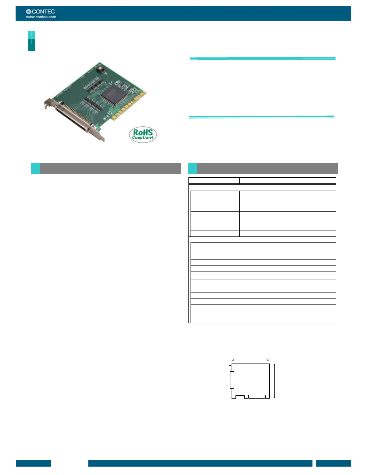
PCI-compliant Digital Input Board
DI-64T2-PCI
* Specifications, color and design of the products are subject to
change without notice.
This product is a PCI board designed for extending input function
on your PC. It has 64channels of TTL level inputs with a
200nsec response speed. 64ch of input signals can be used as
interrupts. A digital filter is provided to prevent input signal
errors from noise or chattering.
Both Windows and Linux drivers are included with this board.
CONTEC provides drivers that enable these boards to be
used with LabVIEW.
64ch of unisolated TTL level input
This board has 64ch of unisolated TTL level input with a 200μsec
response speed.
32ch of input signals can be used as interrupt events.
You can use 32ch input signals as interrupt events and also
disable or enable the interrupt in bit units and select the interrupt
edge.
Digital filter prevents input signal errors from noise or
chattering.
A digital filter is provided to prevent input signal errors from noise
or chattering. This filter can be added to each input terminal,
with settings performed via software.
Windows and Linux driver libraries are included
The included driver library [API-PAC(W32)] makes it possible to
create applications in both Windows and Linux environments. A
diagnostic program to check the hardware operation is also
provided.
LabVIEW support
LabVIEW is supported by using CONTEC’s dedicated library
VI-DAQ.
Item Specification
Input
Input format Unisolated TTL level input (Negative logic *1)
Number of input signal
channels
64channels (32channels of them are available for interrupts) (1
common)
Input resistance
Pull up 10kΩ (1TTL load)
Interrupt 32 interrupt input signals are arranged into a single output of
interrupt signal INTA.
An interrupt is generated at the rising edge (HIGH-to-LOW
transition) or falling edge (LOW-to-HIGH transition).
Response time 200nsec within
Common
External supply capable current
(Max.)
5VDC 1A
Allowable distance of signal
extension
Approx. 1.5m (depending on wiring environment)
I/O address Any 32-byte boundary
Interrupt Level 1 level use
Max. board count for
connection
16 boards including the master board
Power consumption (Max.) 5VDC 200mA
Operating condition
0 - 50°C, 10 - 90%RH (No condensation)
Bus specification
PCI (32bit, 33MHz, Universal key shapes supported *2)
Dimension (mm)
121.69(L) x 105.68(H)
Connector
96 pin half pitch connector [F (female) type]
PCR-E96LMD+ [HONDA TSUSHIN KOGYO CO., LTD.]
equivalent to it
Weight
100g
*1: Data “0” and “1” correspond to the High and Low levels, respectively.
*2: This board requires power supply at +5V from an expansion slot (it does not work on a
machine with a +3.3V power supply alone).
Board Dimensions
[mm]
121.69(L)
105.68(H)
The standard outside dimension (L) is
the distance from the end of the board to
the outer surface of the slot cover.
Features
Specifications
Page 2
Ver.1.02
DI-64T2-PCI 2
API-DIO(WDM)/API-DIO(98/PC)
Digital I/O driver for Windows
[Found on the included CD-ROM driver library API-PAC(W32)]
For use in Windows environments, API-DIO(98/PC) is driver
library software that provides basic Win32 API functions (DLL).
Various sample programs using Visual Basic and Visual C++ and
a diagnostic program used to check the hardware operation are
also provided.
< Operating Environments >
Operating Systems: Windows Vista, Windows XP, Server 2003,
2000
Programming languages: Visual Basic, Visual C++, Visual C#,
Delphi, C++ Builder
Upgraded software versions can be downloaded from CONTEC’s
document site (http://www.contec.com/apipac/).
For more details on supported OS, programming languages and
for updated information, please visit CONTEC’s Web site.
API-DIO(LNX)
Digital I/O driver for Linux
[Found on the included CD-ROM driver library API-PAC(W32)]
API-DIO(LNX) is driver software for Linux which provides device
drivers (modules) by shared library and kernel versions.
Various sample gcc programs are provided.
< Operating Environments >
Operating Systems: RedHatLinux, TurboLinux
(For details on supported distributions, refer to Help files that are
available after installation.)
Programming language: gcc
Upgraded software versions can be downloaded from CONTEC’s
document site (http://www.contec.com/apipac/).
For more details on supported OS, programming languages and
for updated information, please visit CONTEC’s Web site.
VI-DAQ
Data acquisition VI library for LabVIEW
[Available for free download from CONTEC’s web site]
CONTEC’s VI library is for use with National Instruments’
LabVIEW.
VI-DAQ is designed with functions similar to that of LabVIEW's
Data Acquisition VI, allowing various devices to be used without
complicated settings.
For more details and to download VI-DAQ go to
http://www.contec.com/vidaq/.
Shield Cable with 96-Pin Half-Pitch Connectors at Both Ends
: PCB96PS-0.5P (0.5m)
: PCB96PS-1.5P (1.5m)
Flat Cable with 96-Pin Half-Pitch Connectors at Both Ends
: PCB96P-1.5 (1.5m)
Shield Cable with 96-Pin Half-Pitch Connectors at One End
: PCA96PS-0.5P (0.5m)
: PCA96PS-1.5P (1.5m)
Flat Cable with 96-Pin Half-Pitch Connectors at One End
: PCA96P-1.5 (1.5m)
Distribution shield cable with 96-Pin Half-Pitch Connectors
(96P→37P x 2) : PCB96WS-1.5P (1.5m)
Half Pitch 96P Female Connector Set (5 Pieces)
: CN5-H96F
Screw Terminal (M3 x 96) :EPD-96A *1
Terminal Unit for Relay Terminal Banks :EPD-96 *1
Screw Terminal :DTP-64(PC) *1
Signal Monitor for Digital I/O (64Bits) :CM-64(PC)E *1
Screw Terminal Unit (M3 x 37P) :EPD-37A *2
Screw Terminal Unit (M3.5 x 37P) :EPD-37 *2
General Purpose Terminal :DTP-3A *2
Screw Terminal :DTP-4A *2
Signal Monitor for Digital I/O :CM-32(PC)E *2
Connection Conversion Board (96-Pin → 37-Pin x 2)
:CCB-96 *3
*1: A PCB96P or PCB96PS optional cable is required separately.
*2: A PCB96WS optional cable is required separately.
*3: Option cable PCB96P or PCB96PS, and the cable for 37-pin D-SUB are required separately.
Board [DI-64T2-PCI] …1
First step guide … 1
CD-ROM *1 [API-PAC(W32)] …1
*1 The CD-ROM contains the driver software and User’s Guide.
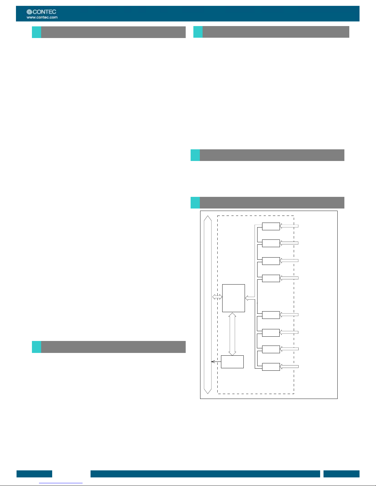
DI-64T2-PCI
Control
Circuits
PCI Express BUS
Interrupt
Control
Circuit
TTL
receiver
TTL
receiver
TTL
receiver
TTL
receiver
TTL
receiver
TTL
receiver
TTL
receiver
TTL
receiver
External digita l
input Port 0
(8 channels, Group 0)
External digita l
Input Port 1
(8 channels, Group 1)
External digital
Input Port 2
(8 channels, Group 2)
External digital
Input Port 3
(8 channels, Group 3)
External digital
Input Port 4
(8 channels, Group 4)
External digital
Input Port 5
(8 channels, Group 5)
External digital
Input Port 6
(8 channels, Group 6)
External digital
Input Port 7
(8 channels, Group 7)
Packing List
Support Software
Optional Cables and Connectors
Accessories
Block Diagrams
Page 3
Ver.1.02
DI-64T2-PCI 3
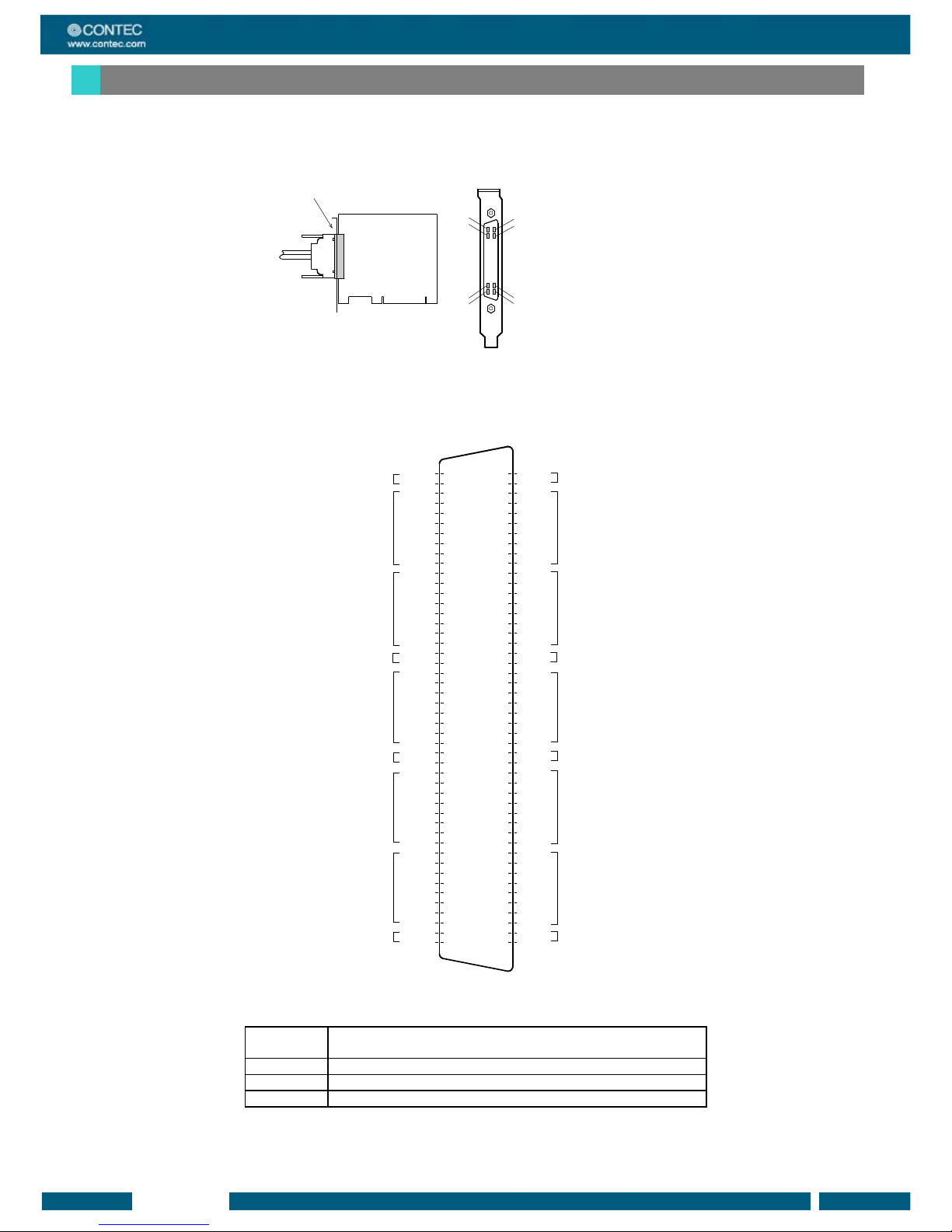
Connector shape
The on-board interface connector (CN1) is used when connecting this product and the external devices.
B48
B47
A48
A47
A02
A01
B02
B01
Interface connector (CN1)
- Connector used
PCR-E96LMD+equivalent to it
[mfd. by HONDA TSUSHIN
KOGYO CO., LTD.]
- Applicable connectors
PCR-E96FA+equivalent to it
[mfd. by HONDA TSUSHIN
KOGYO CO., LTD.]
Connector Pin Assignment
Pin Assignments of Interface Connector (CN1)
Vcc
Vcc
I-37
I-36
I-35
I-34
I-33
I-32
I-31
I-30
I-27
I-26
I-25
I-24
I-23
I-22
I-21
I-20
GND
GND
N.C.
N.C.
N.C.
N.C.
N.C.
N.C.
N.C.
N.C.
Vcc
Vcc
I-17
I-16
I-15
I-14
I-13
I-12
I-11
I-10
I-07
I-06
I-05
I-04
I-03
I-02
I-01
I-00
GND
GND
Vcc
Vcc
I-77
I-76
I-75
I-74
I-73
I-72
I-71
I-70
I-67
I-66
I-65
I-64
I-63
I-62
I-61
I-60
GND
GND
N.C.
N.C.
N.C.
N.C.
N.C.
N.C.
N.C.
N.C.
Vcc
Vcc
I-57
I-56
I-55
I-54
I-53
I-52
I-51
I-50
I-47
I-46
I-45
I-44
I-43
I-42
I-41
I-40
GND
GND
+7 port (input)
N.C.
+6 port (input)
+5 port (input)
+4 port (input)
+5V
Signal common
+2 port (input)
+3 port (input)
+1 port (input)
+0 port (input)
+5V
N.C.
+5V
Signal common
[49]
[1]
[96] [48]
B48
B47
B46
B45
B44
B43
B42
B41
B40
B39
B38
B37
B36
B35
B34
B33
B32
B31
B30
B29
B28
B27
B26
B25
B24
B23
B22
B21
B20
B19
B18
B17
B16
B15
B14
B13
B12
B11
B10
B09
B08
B07
B06
B05
B04
B03
B02
B01
A48
A47
A46
A45
A44
A43
A42
A41
A40
A39
A38
A37
A36
A35
A34
A33
A32
A31
A30
A29
A28
A27
A26
A25
A24
A23
A22
A21
A20
A19
A18
A17
A16
A15
A14
A13
A12
A11
A10
A09
A08
A07
A06
A05
A04
A03
A02
A01
Signal commonSignal common
+5V
* I-00 - I-37 can be used as interrupt signal.
* The numbers in square brackets [ ] are pin numbers designated by HONDA TSUSHIN KOGYO CO., LTD.
I-00 - I-77 64 input signal pins. Connect output signals from the external
device to these pins.
Vcc Output +5V. Max. electrical current is 1A.
GND This pin is connected to GND in the slot.
N.C. This pin is left unconnected.
On-board connector wiring
Page 4
Ver.1.02
DI-64T2-PCI 4
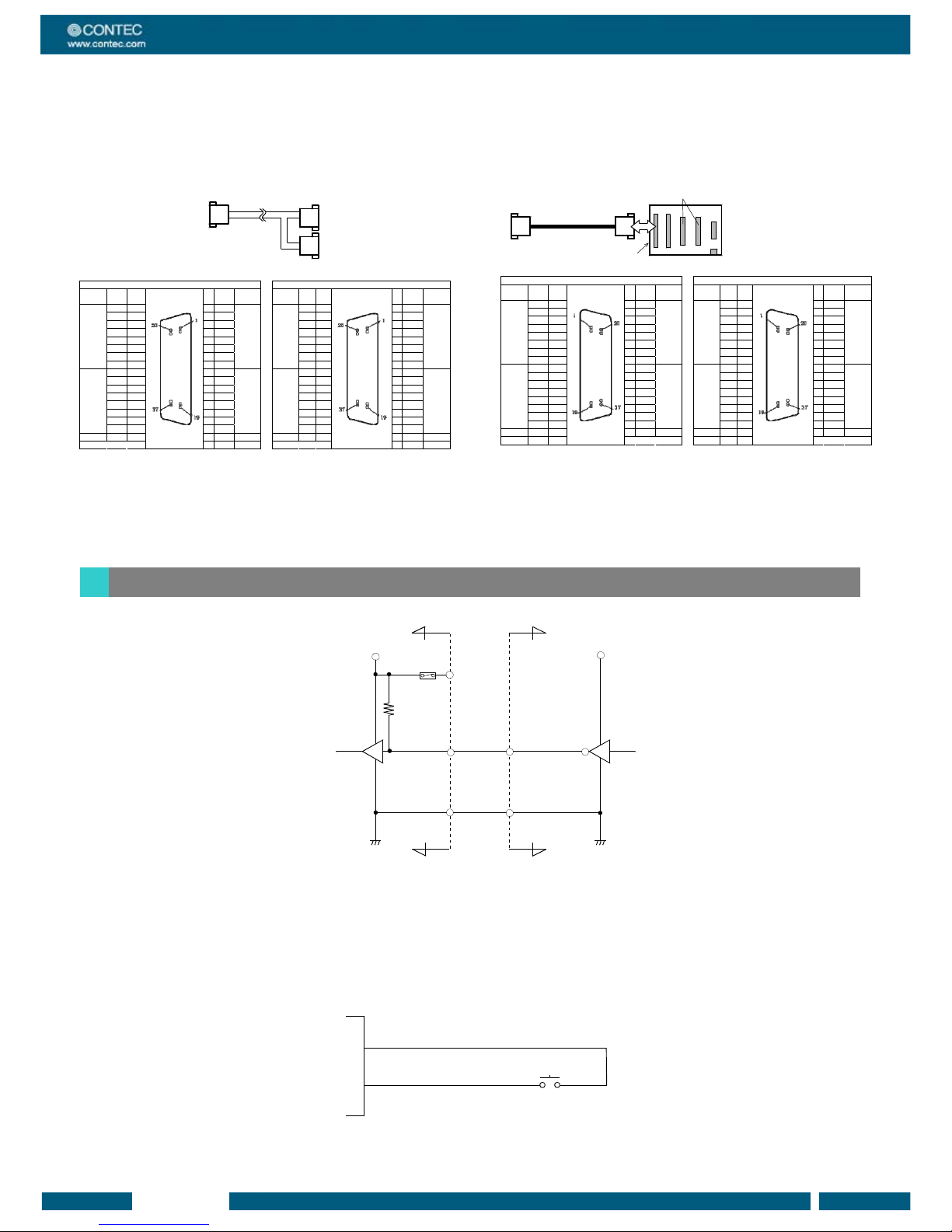
Pin Assignments of PCB96WS or CCB-96
The following shows the correspondence between the option cable pins and signals.
< Pin assignments for connecting a PCB-96WS to the
DI-64T2-PCI >
- Optional cable PCB96WS
A
B
CNA CNB
Signal
common
GND 20 1 GND
Signal
common
Signal
common
GND 20 1 GND
Signal
common
I-20 21 2 I-00 I-60 21 2 I-40
I-21 22 3 I-01 I-61 22 3 I-41
I-22 23 4 I-02 I-62 23 4 I-42
I-23 24 5 I-03 I-63 24 5 I-43
I-24 25 6 I-04 I-64 25 6 I-44
I-25 26 7 I-05 I-65 26 7 I-45
I-26 27 8 I-06 I-66 27 8 I-46
+2 port
(input)
I-27 28 9 I-07
+0 port
(input)
+6 port
(input)
I-67 28 9 I-47
+4 port
(input)
I-30 29 10 I-10 I-70 29 10 I-50
I-31 30 11 I-11 I-71 30 11 I-51
I-32 31 12 I-12 I-72 31 12 I-52
I-33 32 13 I-13 I-73 32 13 I-53
I-34 33 14 I-14 I-74 33 14 I-54
I-35 34 15 I-15 I-75 34 15 I-55
I-36 35 16 I-16 I-76 35 16 I-56
+3 port
(input)
I-37 36 17 I-17
+1 port
(input)
+7 port
(input)
I-77 36 17 I-57
+5 port
(input)
+5V Vcc 37 18 Vcc +5V +5V Vcc 37 18 Vcc +5V
19 N.C.
19 N.C.
< Pin assignments for connecting a CCB-96 to the
DI-64T2-PCI >
- "Optional cable PCB96PS"
+ "Connector conversion board CCB-96"
Connector DCLC-J37SAF-20L9
or equivalence to it (mfd by JAE)
CCB-96
CN3(CNA) CN4(CNB)
Signal
common
GND 1 20 GND
Signal
common
Signal
common
GND 1 20 GND
Signal
common
I-00 2 21 I-20 I-40 2 21 I-60
I-01 3 22 I-21 I-41 3 22 I-61
I-02 4 23 I-22 I-42 4 23 I-62
I-03 5 24 I-23 I-43 5 24 I-63
I-04 6 25 I-24 I-44 6 25 I-64
I-05 7 26 I-25 I-45 7 26 I-65
I-06 8 27 I-26 I-46 8 27 I-66
+0 port
(input)
I-07 9 28 I-27
+2 port
(input)
+4 port
(input)
I-47 9 28 I-67
+6 port
(input)
I-10 10 29 I-30 I-50 10 29 I-70
I-11 11 30 I-31 I-51 11 30 I-71
I-12 12 31 I-32 I-52 12 31 I-72
I-13 13 32 I-33 I-53 13 32 I-73
I-14 14 33 I-34 I-54 14 33 I-74
I-15 15 34 I-35 I-55 15 34 I-75
I-16 16 35 I-36 I-56 16 35 I-76
+1 port
(input)
I-17 17 36 I-37
+3 port
(input)
+5 port
(input)
I-57 17 36 I-77
+7 port
(input)
+5V Vcc 18 37 Vcc +5V +5V Vcc 18 37 Vcc +5V
N.C. 19 N.C. 19
Input Circuit
External dev ice
Input pin
Signal
common
Vcc
+5V output
GNDGND
Vcc
74ALS541
10kΩ
Board
PolySwitch
* I-xx represents an input pin.
One polyswitch is connected for Vcc(+5V) terminal.
The input circuit of interface is illustrated above.
External digital signals given to signal inputs are TTL levels. The individual input signals are passed to the personal computer as
negative logic signals. As each of the signal inputs is pulled up internally, the output of a relay contact or semiconductor switch can be
connected directly between the signal input and the signal common pin.
Connecting a Switch
GND (CN1 : A01 pin)
Board
I-00 (CN1 : A03 pin)
Switch
When the switch is ON, the corresponding bit contains 1.
When the switch is OFF, by contrast, the bit contains 0.
Connection of Input Signals
 Loading...