

Page 1

PC-HELPER
Digital I/O Board
for PCI Express
DIO-3232L-PE
Digital Input Board with Opto-Isolation
DI-64L-PE
Digital Output Board with Opto-Isolation
DO-64L-PE
User’s Guide
CONTEC CO.,LTD.
Page 2
Board
Disk
[API-PAC(W32)]
First step guide
First st ep guide
Serial Number LabelWarranty Certificate
Warrant y Certifi cate
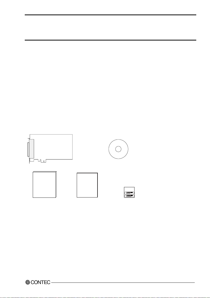
Check Your P a ckage
Thank you for purchasing the CONTEC product.
The product consists of the items listed below.
Check, with the following list, that your package is complete. I f y ou discover damaged or missing
items, contact your retailer.
Product Configuration List
- Board (One of the followings)
[DIO-3232L-PE, DI -64L-PE or DO -64L-PE] …1
- First step guide … 1
- Disk *1 [ A P I-PAC(W32)] …1
- Warranty Certificate …1
- Serial number label …1
*1 The bundled disk contains the driver software and User’s Guide (this guide)
DIO-3232L-PE, DI-64L-PE, DO-64L-PE
i
Page 3

Copyright
Copyright 2013 CONTEC CO., LT D. AL L RIG HT S R ESE R VE D.
No part of this document may be copied or reproduced in any form by any means without prior written
consent of C ONTEC CO., LT D.
CONTEC CO., LTD. makes no commitment to update or keep current the information contained in
this document. The information in this document is subject to change without notice.
All relevant issues have been considered in the preparation of this document. Should you notice an
omission or any questionable item in this document, please feel free to notify CONTEC CO., LTD.
Regardless of the foregoing statement, CONTE C assumes no responsibil ity for any errors that may
appear in this document or for results obtained by the user as a result of using this product.
Trademarks
MS, Microsoft, Windows and MS-DOS are tra demark s of Micr osoft C orporation. Other brand and
product names are tradema rk s of th eir r especti ve hol der.
DIO-3232L-PE, DI-64L-PE, DO-64L-PE
ii
Page 4
Table of Contents
Check Your Package ................................................................................................................................... i
Copyright ..................................................................................................................................................... ii
Trademarks .................................................................................................................................................. ii
Table of Contents ....................................................................................................................................... iii
1. BEFORE USIN G TH E PRODUCT 1
About the Board .......................................................................................................................................... 1
Features ................................................................................................................................................. 1
Support Software ................................................................................................................................. 3
Cable & Connector (Option) .............................................................................................................. 4
Accessories (Opti on) ........................................................................................................................... 5
Customer Support ....................................................................................................................................... 6
Web S it e ............................................................................................................................................... 6
Limited Thre e-Years Warranty ................................................................................................................. 6
How to Obtain Service ............................................................................................................................... 6
Liability ........................................................................................................................................................ 6
Safety Precautions....................................................................................................................................... 7
Safety Information ............................................................................................................................... 7
Handling Precautions .......................................................................................................................... 8
Environment ....................................................................................................................................... 10
Inspection ........................................................................................................................................... 10
Storage ................................................................................................................................................ 10
Disposal .............................................................................................................................................. 10
2. SETUP 11
What is Setup?........................................................................................................................................... 11
Using the Board under Windows Using the Driver Library API-PAC(W32) ............................ 11
Using the Board under an OS Other than Windows ...................................................................... 11
Step 1 Installing the Software.................................................................................................................. 12
About the driver to be used .............................................................................................................. 12
Select API-DIO(WDM) .................................................................................................................... 14
Step 2 Setting the Hardware .................................................................................................................... 15
Parts of the Board and Factory Defaults ......................................................................................... 15
Setting the Board ID.......................................................................................................................... 16
Plugging th e Board ............................................................................................................................ 17
Step 3 Installing the Hardware ................................................................................................................ 18
Turning on the PC ............................................................................................................................. 18
Found New Hardware Wizard Se tt ing ................................................................................................. 19
Step 4 Initializing the Software ............................................................................................................... 20
DIO-3232L-PE, DI-64L-PE, DO-64L-PE
iii
Page 5
Step 5 Operation Checks .......................................................................................................................... 22
Check Method .................................................................................................................................... 22
Setup Troubleshooting ............................................................................................................................. 25
Symptoms and Actions ..................................................................................................................... 25
3. EXTERN AL CONNE CTION 27
How to connect the connectors ............................................................................................................... 27
Connector shape ................................................................................................................................ 27
Connector Pin Assignment ............................................................................................................... 28
Relationships between API-PAC(W32) Logical Ports/Bits and Connector Signal Pins ........... 35
Connecting Input Signals ......................................................................................................................... 37
Input Circuit ....................................................................................................................................... 37
Connecting a Switch ......................................................................................................................... 37
Connecting Output Signals ...................................................................................................................... 38
Output Circuit .................................................................................................................................... 38
Connection to the LED ..................................................................................................................... 39
Example of Connection to TTL Level Input .................................................................................. 39
Connecting the Sink Type Output and Sink Output Support Input ..................................................... 40
4. FUNCTION 41
Data I/O Function ..................................................................................................................................... 41
Data Input ........................................................................................................................................... 41
Data Out put ........................................................................................................................................ 41
Monitoring Output Data ................................................................................................................... 41
Digital Filter Function .............................................................................................................................. 42
Digital Filter Function Principle ...................................................................................................... 42
Set Digital Filter Time ...................................................................................................................... 42
Interrupt Control Function ....................................................................................................................... 43
Disabling/enabling Interrupts ........................................................................................................... 43
Selecting the Edge of input signals, at which to generate an iterrupt.......................................... 43
Clearing the Interrupt Status and Interrupt Signal ......................................................................... 43
5. ABOUT SOF TWARE 45
About Software for Windows .................................................................................................................. 45
Accessing the Help File .................................................................................................................... 45
Using Sample Programs ................................................................................................................... 46
Uninstalling the Driver Libraries ..................................................................................................... 47
About Software for Linux ........................................................................................................................ 48
Driver Software Install Procedure ................................................................................................... 48
Accessing the Help File .................................................................................................................... 49
Using Sample Programs ................................................................................................................... 49
Uninstalling the driver ...................................................................................................................... 49
DIO-3232L-PE, DI-64L-PE, DO-64L-PE
iv
Page 6
6. ABOUT HARDWARE 51
For detailed technical information .......................................................................................................... 51
Hardware specificat io n ............................................................................................................................. 51
Block Diagram .......................................................................................................................................... 56
DIO-3232L-PE, DI-64L-PE, DO-64L-PE
v
Page 7

DIO-3232L-PE, DI-64L-PE, DO-64L-PE
vi
Page 8

1. Before Usin g th e Produ ct
1. Befo re Using the Product
This chapter provides informati on you should know before using the product.
About the Board
This product is a PCI Express bus-compliant interface board that extends the digital signal I/O
functions of a PC.
DIO-3232L-P E i s a 12 - 24VDC opto-coupler isolated type with opto-coupler isolated input 32ch and
opto-coupler isolated open-collector output 32ch. You can use all of the input signals as interrupt
inputs. Equipped with the digital filter function and output transistor protection circuit (surge voltage
protection and overcurrent protection).
DI-64L-PE i s a 12 - 24VDC opto-coupl er isolated type with input 64ch. You can use 32ch of the input
signals as interrupt inputs. In addition, digital filter function to prevent wrong recognition of input
signals i s provided.
DO-64L-PE is a 12 - 24VDC opto-coupler isolated type with open-collector output 64ch. Equi pped with
the output transistor protection circuit (surge voltage protection and overcurrent protection).
Windows/Linux driver is bundled with this product.
Features
Opto-coupler isolated input (supporting current sink output) and opto-cou pler isolated open-collector
output (current sink type)
DIO-3232L-PE has the opto-coupler isolated input 32ch ( supporting current sink output) whose
response speed is 200µsec and opto-coupler isolated open-collector output 32ch (current sink type).
DI-64L-PE has the opto-coupler isolated input 64ch (supporting current sink output) whose response
speed is 200µsec.
DO-64L-PE h a s the opto-cou pler isolated open-coll ect or out put 64ch (supporting current sink output)
whose response speed i s 200µsec.
Common terminal provided per 16ch, capable of supporting a different external power supply
Supporting driver voltages of 12 - 24 VD C fo r I /O
Opto-coupler bus isolation
As the PCI Express bu s (PC) is isolated from the input and output interfaces by opto-couplers, this
product has excellent noise perfor ma nce.
You can use all of the input signals as interrupt request signals.
You can use all of the input signals as interrupt request signals and also disable or enable the interrupt
in bit units and select the edge of the input signals, at which to generate an interrupt.
DIO-3232L-PE, DI-64L-PE, DO-64L-PE
1
Page 9

1. Befor e U s in g t h e Produ ct
Windows/Linux compatible driver libraries are attached.
Using the attached driver library API-PAC(W32) makes i t p ossi bl e to create applications of
Windows/Linux. In addition, a diagnostic program by which the operations of hardware can be
checked is provided.
This product has a digital filter to prevent wrong recognition of input signals from carrying noise or a
chattering.
This product has a digital filter to prevent wrong recognition of input signals from carrying noise or a
chattering. All input terminals can be added a digital filter, and the setting can be performed by
software.
The output circuit, has a built-in Zener diode and the overcurrent protection circuit of the surge
voltage protection.
Zener diodes are connected to the output circuits to protect against surge voltages. In addition, the
output circuit, it attaches the overcurrent protection circuit at the output 8-channel unit.
The output rating is max. 35VDC, 100mA per ch.
Functions and connectors are compatible with PCI compatible board PIO-32/32L(PCI)H series.
DIO-3232L-PE : The functions same with PCI compatible board PIO -32/32L(PCI)H are provided.
DI-64L-PE : The functions same with PCI compatible board PI-64L(PCI)H are provided.
DO-64L-PE : The functions same with PCI compatible board PO-64L(PCI)H are provided.
In addition, as there is compatibility in terms of connector shape and pin assignments, it is easy t o
migrate from the existing system.
LabVIEW is supported by a plug-in of dedicated library.
Using the dedicated library makes it possible to make a LabVIEW application.
DIO-3232L-PE, DI-64L-PE, DO-64L-PE
2
Page 10

1. Before Usin g th e Produ ct
Support Software
You should use CONTEC support software according to your purpose and development environment.
Windows version of digital I/O driver
Stored on the bundled disk dr iver library API-PAC(W32)]
[
The API -DI O(WDM) is the Windows version driver library software that provides products in the form of Win32
API functions (DLL). Various sample programs such as Visual Basic and Visual C++, etc and diagnostic program
*1useful for checking operation is provided.
For more details on the supported OS, applicable language and how to download the updated version, please visit the
CONTEC’s Web site (h ttp://www.contec.com/apipac/).
API-DIO(WDM)/API-DIO(98/PC)
Linux version of digital I/O driver
Stored on the bundled disk dr iver library API-PAC(W32)]
[
The API -DI O(LNX) is the Linux version driver software which provides device drivers (modules) by shared library
and kernel version. Various sample programs of gcc are provided.
For more details on the supported OS, applicable language and how to download the updated version, please visit the
CONTEC’s Web site (h ttp://www.contec.com/apipac/).
Data acquisition library for LabVIEW
API-DIO(LNX)
VI-DAQ
(Available for downloading (free of charge) from the
CONTEC web si t e.)
This is a VI library to use in National Instruments LabVIEW.
VI-DAQ is created with a function form similar to that of LabVIEW' s Data Acquisition VI, allowing you to use
various devices without complicated settings.
See http://www.contec.com/vidaq/ for details and download of VI-DAQ.
DIO-3232L-PE, DI-64L-PE, DO-64L-PE
3
Page 11

1. Befor e U s in g t h e Produ ct
Cable & Connector (Option)
Shield Cable with 96-Pin Half -Pitch Connectors at Both Ends
: PCB96PS-0.5P (0.5m)
: PCB96PS-1.5P (1.5m)
: PCB96PS-3P (3m)
: PCB96PS-5P (5m)
Flat Cable with 96-Pin Half-Pitch Connectors at Both Ends
: PCB96P-1.5 (1.5m)
: PCB96P-3 (3m)
Shield Cable with 96-Pin Half -Pitch Connectors at One End
: PCA96PS-0.5P (0.5m)
: PCA96PS-1.5P (1.5m)
: PCA96PS-3P (3m)
: PCA96PS-5P (5m)
Flat Cable with 96-Pin Half-Pitch Connectors at One End
: PCA96P-1.5 (1.5m)
: PCA96P-3 (3m)
Distribution shield cable with 96-Pin Half-Pitch Connectors(96P→37P x 2)
: PCB96WS-1.5P (1.5m)
: PCB96WS-3P (3m)
: PCB96WS-5P (5m)
DIO-3232L-PE, DI-64L-PE, DO-64L-PE
4
Page 12

1. Before Usin g th e Produ ct
Accessories (Option)
Screw Terminal : EPD-96A *1*2
Screw Terminal : EPD-96 *1
Digital I/O 64CH Series Terminal Panel (M3 x 96P) : DTP-64A *1
Signal Monitor for Digital I/O(64Bits) : CM-64L *1
Screw Terminal (M3 x 37P) : EPD-37A *3
Screw Terminal (M3.5 x 37P) : EPD-37 *3
General Purpose Terminal (M3 x 37P) : DTP-3C *3
Screw Terminal (M2.5 x 37P) : DTP-4C *3
Signal Monitor for Digital I/O : CM-32L *3
Connection Conversion Board (96-Pin → 37-Pin x 2) : CCB-96 *4
*1 A PCB96P or PCB96P S optional cable is required separately.
*2 "Spring-u p" type terminal is used to prevent terminal screws from falling off.
*3 A PCB96WS optional cable is required separat ely.
*4 Option cable PCB96P or PCB96PS, and the cable for 37-pin D-SUB are required separat el y.
* Check the CONTEC’s Web site for more information on these options.
DIO-3232L-PE, DI-64L-PE, DO-64L-PE
5
Page 13

1. Befor e U s in g t h e Produ ct
Customer Suppo rt
CONTEC provides the following support services for you to use CONTE C produ cts mor e efficient l y
and comfortably.
Web Site
Japanese http://www.contec.co.jp/
English http://www.contec.com/
Chinese http://www.contec.com.cn/
Latest product information
CONTEC provides up-to-da te infor mation on products.
CONTEC also provides product manuals and various technical documents in the PDF.
Free download
You can download updated driver software and differential files as well as sample programs available
in several languages.
Note! For product information
Contact your retailer i f you have any technical question about a CONTEC produ ct or need its price,
delivery time, or estimate information.
Limited Three-Years Warranty
CONTEC products are warra n te d b y CONTEC CO., LTD . t o be free from defects i n mater ia l an d
workmanship for up to three years from the date of purchase by the original purchaser.
Repair will be free of charge only when this device is returned freight prepaid with a copy of the
original invoice and a Return Merchandise Authorization to the distributor or the CONTEC group
office, from which it wa s pur chased.
This warranty is not applicable for scratches or normal wear, but only for the electronic circuitry and
original products. The warranty is not applicable if the device has been tampered with or damaged
thr ough abuse, mistreatment, neglect, or unreasonable use, or if the original invoice is not included, in
which case repairs will be considered beyond the warranty policy.
How to Obtain Service
For replacement or repai r, r eturn t he devi ce frei ght prep aid, wit h a copy of the original invoice. Please
obtain a Return Merchandise Authorization number (RM A) fr om the CO NTE C gr oup office wh er e
you purchased before returning any product.
* No product will be accepted by CONTEC group without the RMA number.
Liability
The obligation of the warrantor is solely to repair or replace the product. In no event will the
warrantor be liable for any incidental or consequential damages due to such defect or consequences
that arise from inexperienced usage, misuse, or malfunction of this device.
DIO-3232L-PE, DI-64L-PE, DO-64L-PE
6
Page 14
1. Before Usin g th e Produ ct
DANGER
WARNING
C
AUTION
Safety Precautions
Understand the following definitions and precautions to use the product safely.
Safety Information
This document provides safety information using the following symbols to prevent accidents resulting
in injury or death and the destruction of equipment and resources. Understand the meanings of these
labels to operate the equi pment sa fely.
DANGER indicates an imminently hazardous situation which, if not avoided, will
result in death or serious injury.
WARNING indicates a potentially hazardous situation which, if not avoided, could
result in death or serious injury.
CAUTION indicates a potentially hazardous situation which, if not avoided, may
result in minor or moderate injury or in property damage.
DIO-3232L-PE, DI-64L-PE, DO-64L-PE
7
Page 15
1. Befor e U s in g t h e Produ ct
D
ANGER
CA
UTI
ON
Handling Pre c autions
D o not use the product where it is exposed to flammable or corrosive gas. Doing so may result in
an explosion, fire, elect ric shock , or failu re.
- Th ere are swit ches on th e boar d t hat n eed to be set in ad vance. Be sure to check these before
installing the board.
- O nly set the switches and jumpers on the board to the specified settings.
Otherwise, the board may malfunction, overheat, or cause a failure.
- D o not strike or bend the board. Doing so could damage the board.
Otherwise, the board may malfunction, overheat, cause a failure or breakage.
- D o not touch the board's metal plated terminals (edge connector) with your hands.
Otherwise, the board may malfunction, overheat, or cause a failure.
If the terminals are touched by someone's hands, clean the terminals with industrial alcohol.
- Do not install or remove the board to or from the extension slot while the computer's power is turned
on. And also do not connect the board and external device while the power is turned on.
Otherwise, the board may malfunction, overheat, or cause a failure.
Be sure that the personal compute r or the I/O extension unit power is turned off.
- Make sur e t hat y our PC or extension unit can supply ample power to all the boards installed.
Insufficiently energized boards could malfunction, overheat, or cause a failure.
- The specifications of this product ar e subject to change without notice for enhancement and
quality i mprovement.
Even when using the product continuously, be sure to read the manual and understand the
contents.
- D o not modify the product. CONTEC will bear no responsibility for any problems, etc., resulting
from modifying this product.
- Rega rdle s s of the foregoing statements, CONTEC is not liable for any damages whatsoever
(including damages for loss of business profits) arising out of the use or inability to use this
CONTEC product or the information contained herein.
DIO-3232L-PE, DI-64L-PE, DO-64L-PE
8
Page 16
1. Before Us i n g the Product
Name
Maker
Turn
Quantity
Installation Site
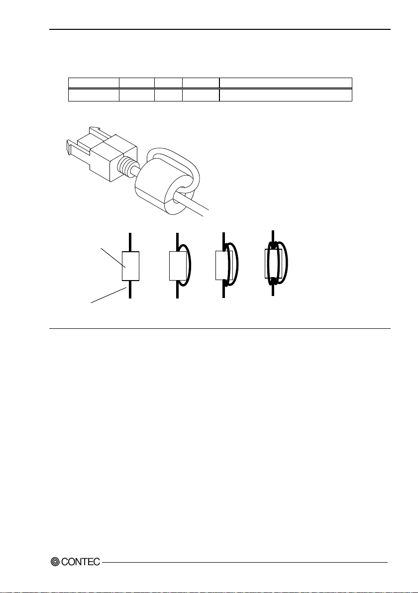
- Regarding “CE EMC Directive Cla ss A N o tice ”
The ferrite core must be instal led in inter face connect in g ca bl e so tha t this produ ct (DI-64L-PE)
may suit the above-mentioned standard.
E04SR301334 SEIWA 1 2 each one on each I/O cable at product side
I mage diagram
Ferrite core
Cable
TURN : 1
TURN : 2
TURN : 3
TURN : 4
DIO-3232L-PE, DI-64L-PE, DO-64L-PE
9
Page 17
1. Befor e U s in g t h e Produ ct
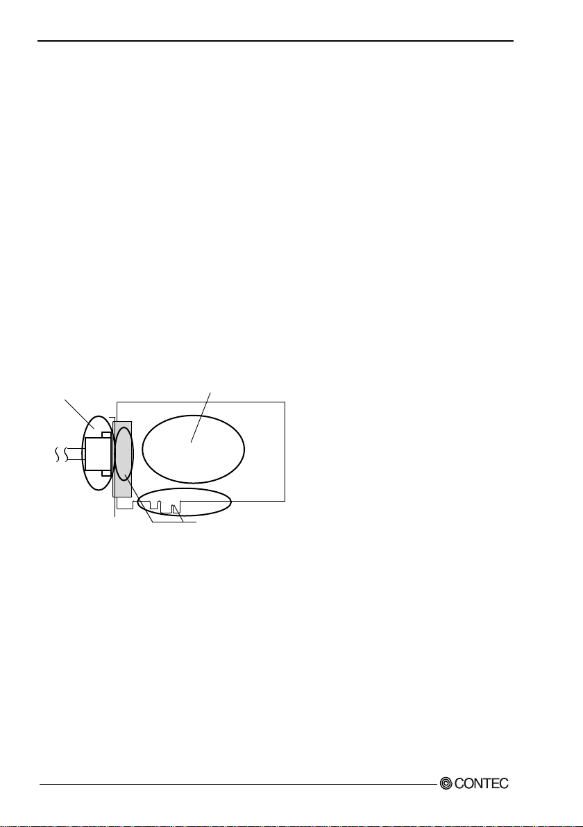
-
Che
ck t
hat
t
he
b
o
ar
d
h
as
n
o d
ust
or
for
eig
n m
atte
r a
dhe
rin
g.
-
The go
ld-p
lat
ed
lea
ds o
f t
he bu
s conn
ecto
r
h
ave no
stain
or
cor
ros
ion
.
-
Ch
e
ck
th
at
th
e
b
us
co
nne
cto
r
o
f t
he
boar
d a
nd
its cable
have
be
en
pl
ug
g
ed
c
o
rr
e
ctly
.
Environment
Use this product in the following environment. If used in an unauthorized environment, the board may
overheat, malfunction, or cause a failure.
Operating temperature
0 - 50°C
Humidity
10 - 90%RH (No condensation)
Cor rosive gases
None
Floating dust particles
Not to be excessive
Inspection
Inspect the product periodically as follows to use it safely.
Storage
When storing this product, keep it in its original packing form.
(1) Put the board in the storage bag.
(2) Wrap it in the packing material, and then put it in the box.
(3) Store the package at room temperature at a place free from direct sunlight, moisture, shock,
vibration, magnetism, and static electricity.
Disposal
When disposing of the product, follow the disposal procedures stipulated under the relevant laws and
municipal ordinances.
DIO-3232L-PE, DI-64L-PE, DO-64L-PE
10
Page 18

2. Setup
2. Setup
This chapter explains how to set up the board.
What is Setup?
Setup mean s a seri es o f ste p s to take b efore t he produ ct ca n be u sed.
Different steps are required for software and hardware.
The setup procedur e varies wit h t he OS and softwa r e used.
Using the Board und e r Wind ow s
Using the D riv er Lib ra ry A PI-PAC(W32)
This section descri bes the setup pr ocedure to be performed before you can start developing application
programs for the board using the bundled disk “Driver Library API-PAC(W32)”.
Taking the following steps sets up the software and hardware. You can use the diagnosis program
later to check whether the software and hardware function normally.
Step 1 I n s tall i ng the Sof twar e
Step 2 Setting the Hardware
Step 3 Installing the Hardware
Step 4 I n itia lizi ng the Softwar e
Step 5 Operation Checks
If Setup fails to be performed normally, see the “Setup Troubleshooting” section at the end of this
chapter.
Using the Board und e r an OS Othe r than Windows
For using the board under an OS other than Windows, see the following parts of this user’s guide.
T his chapter Step 2 Setting the Hardware
Chapter 3 External Connection
Chapter 6 About Hardware
DIO-3232L-PE, DI-64L-PE, DO-64L-PE
11
Page 19

2. Setup
Step 1 Installing the Software
This section describes how to install the Driver libraries.
Before installing the hardware in a PC, install "Driver Library API-PAC(W32)" from the
bun dl ed media or do wn load and install the latest edition of this software from the CONTEC web
site.
Although some user interfaces are different depending on the OS used, the basic procedure is the
same.
About t h e driver to be used
Two Digital I/O drivers are available : API-DIO(WDM) and API-DIO(98/PC).
When using this product, use the advanced digital I/O driver "API-DIO(WDM)". The following
information is focused on setting up API-DIO(WDM).
If API -DI O(98/PC) usi n g ex i st in g syste m s co nt i nu e t o u se AP I -DIO(98/PC).
Please note that the A P I -D IO(98/PC ) does not support Windows 8 or later, and the 64-bit OS.
Use the API-DIO(98/PC)
If you are installing from disk attachments, select "all" from the "Installer" later in this chapter and
starts the execution environment and development environment packages installer
Please see the Help folder in the instal led har dware i nstallat i on i nstructi ons pl ease see ref er ence i n
help disk attachments or downloaded from
Furthermore , th at applies to the default step 4 software described below, see config.chm folder
installed execution environment
CONTE C ’s Web si te
development environment.
DIO-3232L-PE, DI-64L-PE, DO-64L-PE
12
Page 20
2. Setup
CAUTION
Starting the Install Program
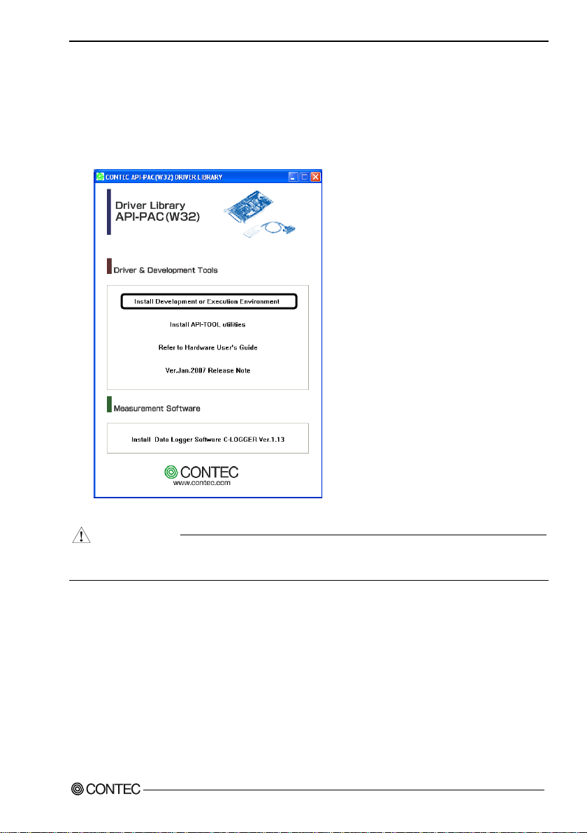
(1)
Load the bundled disk [API-PAC(W32)] on your PC.
(2)
The A PI-PAC(W32) Installer window appears automatically.
If the panel does not appear, run (drive letter):\AUTORUN.exe.
(3)
Click on the [Install Developm ent or Execution Envir onment] button.
B efore installing the software in Windows 2000 or later, log in as a user with administrator
privileges.
DIO-3232L-PE, DI-64L-PE, DO-64L-PE
13
Page 21
2. Setup
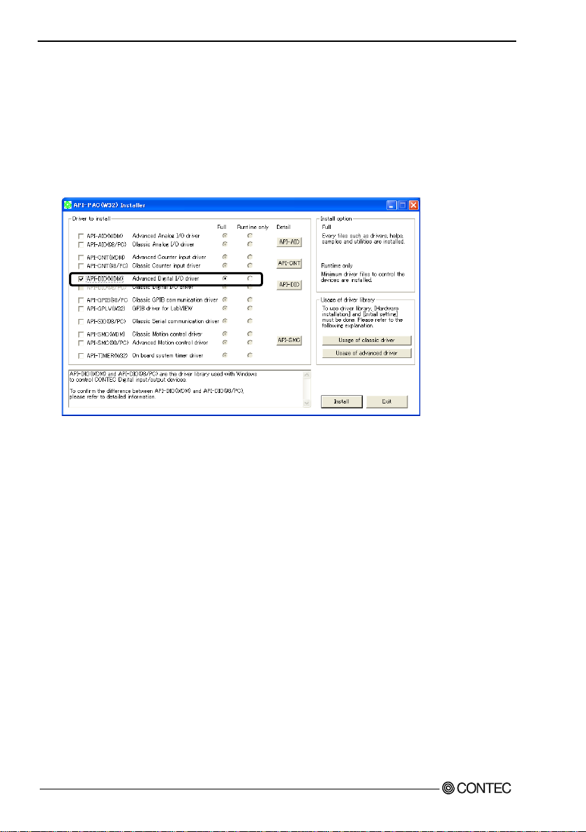
Select API-DIO(WDM)
Selecting API-DIO(WDM)
(1)
The following dialog box appears to select “Driver to install” and “Install option”, “Usage of
driver library”.
(2)
Select the "Advanced Digital I/O driver".
(3)
Click on the [Install] button.
* Clicking the [API-DIO] bu t t on under the “Detail” displays detailed information about
API-DIO(WDM) and API-DIO(98/PC).
Run the installation
(1)
Com plete t h e inst a l l a tio n b y f o l l owing th e instruc tions on t he scr e en.
(2)
The Readme file appears when the installation is complete.
DIO-3232L-PE, DI-64L-PE, DO-64L-PE
14
Page 22

2. Setup
DI
O/DI/DO-xxL-
PE
SW1
BOA
RD
ID
SW1
B
OARD
ID
(SW1)
0
1
2
3
4
5
6
7
9
A
B
C
D
E
F
8
A01
A
02
B02
B
01
A
48
A47
B
48
B47
- B
oard
ID se
ttin
g sw
itch
- In
terfa
ce con
nector
(CN
1)
Step 2 Setting the Har dware
This section describes how to set the board and plug it on your PC.
The board has some swit ches to be pr e set .
Check the on-board switches before plugging the board into an extension slot.
The board can be set up even with the factory defaults untouched. You can change board settings
later.
Parts of the Board and Factory Defaults
Figure 2.1. shows the names of major parts on the board.
Note that the switch setting shown below is the factory default.
Figure 2.1. Component Lo cations
DIO-3232L-PE, DI-64L-PE, DO-64L-PE
15
Page 23

2. Setup
B
OAR
D I
D
(
Boa
r
d
I
D
=
0
)
Fa
ct
or
y
s
et
t
in
g:
SW
1
0
1
2
3
4
5
6
7
9
A
B
C
D
E
F
8
Setting th e Board ID
If you install two or more boards on one personal computer, assign a different ID value to each of the
boards to distinguish them.
The board IDs can be set from 0 to Fh to identify up to sixteen boards.
If only one board is used, the original factory setting (Board ID = 0) should be used.
Setting Procedur e
To set the board ID, use the rotary switch on the board. Turn the SW1 knob to set the board ID as
shown below.
Figure 2.2. Bo ar d ID Settings (SW1 )
DIO-3232L-PE, DI-64L-PE, DO-64L-PE
16
Page 24

2. Setup
CAU
TION
Plugging the Boa rd
(1) Before plugging the board, shut down the system, unplug the power code of your PC.
(2) R emove the cover from the PC so that the board can be mou nted.
(3) P lug the board into an extension slot.
(4) Attach the board bracket to the PC.
(5) Put the cover back into place.
- D o not touch the board's metal plated terminals (edge connector) with your hands.
Otherwise, the board may malfunction, overheat, or cause a failure.
If the terminals are touched by someone's hands, clean the terminals with industrial alcohol.
- D o no t i n sta l l or r e mo v e the board t o or from the slot while the c o mpu ter's or extension unit’s power
is turned on.
Otherwise, the board may malfunction, overheat, or cause a failure.
Be sure that the personal computer power is turned off.
- Make sur e that your PC or extension unit can supply ample power to all the boards installed.
Insufficiently energized boards could malfunction, overheat, or cause a failure.
DIO-3232L-PE, DI-64L-PE, DO-64L-PE
17
Page 25

2. Setup
CAUTION
Step 3 Installing the Hardware
For using an expansion board under Windows, you have to let the OS detect the I/O addr esses and
interrupt level to be used by the board. The process is referred to as installing the hardware.
In the case of using two or more boards, make sure you install one by one with the Add New Hardware
Wizard.
Turning on the PC
Turn on the power to your PC.
- The board cannot be properly installed unless the resources (I/O addresses and interru pt level) for
the board can be allocated. Before attempting to install the board, first determine what PC
resources are free to use.
- The resour ces used by each board do not depend on the location of the PCI Express bus slot or the
board itself. If you remove two or more boards that have already been installed and then remount
one of them on the computer, it is unknown that which one of the sets of resources previously
assigned to the two boards is assigned to the remounted board. In this case, you must check the
resource settings.
DIO-3232L-PE, DI-64L-PE, DO-64L-PE
18
Page 26

2. Setup
Found New Hardware Wizar d Se tting
Depending on the OS that you use, the installation process may start automatically without starting the
wizard. In this situation, proceed to "Step 4 Initializing the Software" section at the end of this chapter.
Performing installations on various operating systems
Help files containing the methods to follow in performing installations on different Windows
operating systems are included on the bundled disk, so refer to the files in the following folder.
\Help\Hwinst\Eng\ApiTool.chm
(1) The “Found New Hard ware W izar d” will be started.
Select “No, not this time” and then click the “Next” button.
(2) When the model name of hardware is displayed, select “Install the software automatically
[Recommended]” and then click on the “Next” button.
The device is automatically installed, and processing is completed.
You have now finished installing the initial setting of Hardware.
DIO-3232L-PE, DI-64L-PE, DO-64L-PE
19
Page 27

2. Setup
* The name of th e board
Step 4 Initial izing the Software
The driver library requires the initial setting to recognize the execution environment. It is called the
initialization of the Driver library.
This software is initialized automatically during hardware installation. Therefore, if you want to use it
with its initial settings, you can skip the setting procedure described in Step 4. To change the device
name, follow the setting procedure shown below.
Setting the device name
(1) Run Device Manager. From [My Computer] - [Control Panel], select [System] and t hen sel ect the
[Device Manager] tab.
(You can also open Device Manager by right clicking on My Computer and selecting Properties.)
you have just added is
displayed.
- DIO-3232L-PE “DIO000”
- DI-64L-PE “DIO000”
- DO-64L-PE “DIO000”
(2) The installed hardware app ears under the CONTEC Dev ices node. O pen the CONT EC Devi ces
node and select the device you want to setup (the device name should appear highlighted). Click
[Properties].
DIO-3232L-PE, DI-64L-PE, DO-64L-PE
20
Page 28

2. Setup
* The name of th e board
- DO-64L-PE
(3) The property page for the device opens.
Enter the device name in the common settings tab page and then click [OK].
The device name you set here is used later when programming.
you have just added is
displayed.
- DIO-3232L-PE
- DI-64L-PE
* The initial device na me that appea r s is a defaul t valu e. You ca n use t his defau lt name i f you wi sh.
* Make sure that you do not use the same name for more tha n one devi ce.
You have now finished installing the initial setting of Software.
DIO-3232L-PE, DI-64L-PE, DO-64L-PE
21
Page 29

2. Setup
Step 5 Ope ration Chec ks
You must make sure that the board and driver software operate normally. By taking this step, you can
make sure that the board has been set up correctly.
Check Method
Connect the board to a remote device to test the input/output and check the execution environment.
Set the board in the defaul t factory.
To connect an exter nal device, see C ha pter 3 “E xternal Connecti on”.
Starting the Diagnosis Program
Open the “Properties” page of the device that was used for the software initialization, and press the
[Diagnosis] button.
DIO-3232L-PE, DI-64L-PE, DO-64L-PE
22
Page 30

2. Setup
* The name of th e board
- DO-64L-PE
Checking Digital Inputs and Outputs
The main panel of the Diagnosis Program appears.
You can check the current operation states of the board in the following boxes:
“Input Por t” : Displays input values bit by bit at fixed time intervals.
“Output Port” : Mouse operation allows the data to output or display.
“Interrupt” : Displays the number of interrupts detected bit by bit.
you have just added is
displayed.
- DIO-3232L-PE
- DI-64L-PE
To use the function execution time measurement feature, click on the [Measurement Time] button.
Enter the I/O start port and the number of ports, then press the measurement button. The time for each
execution of a function will be measured.
DIO-3232L-PE, DI-64L-PE, DO-64L-PE
23
Page 31

2. Setup
CAUTION
* The name of th e board
- DO-64L-PE
Diagnosis Report
(1) Clicking on the [Show Diagnosis Report] button displays detailed data such as board settings and
the diagnosis results while saving them in text format.
The Diagnosis Program performs “board presence/absence check”, “driver file test”, “board
setting test”, and so on.
B efore executing diagnosis report output, unplug t he cable from the board.
you have just added is
displayed.
- DIO-3232L-PE
- DI-64L-PE
DIO-3232L-PE, DI-64L-PE, DO-64L-PE
24
Click on [Show
Diagnosis Report].
Page 32

2. Setup
* The name of th e board
- DO-64L-PE
(2) A diagnosis report is displayed as shown below.
you have just added is
displayed.
- DIO-3232L-PE
- DI-64L-PE
Setup Troubleshooting
Sympto ms and Act ions
The board works with the Diagnosis Program but not with an application.
The Diagnosis Program has been created using the driver API functions. If the board works with the
Diagnosis Program, it will work with other applications. Review the program, paying attention to the
following points.
- Check the retur n values of functions.
- Refer to the source code of sample program.
Refer to the “Troubleshooting” in API-TOOL(WDM) HELP (APITOOL.chm)
DIO-3232L-PE, DI-64L-PE, DO-64L-PE
25
Page 33

2. Setup
DIO-3232L-PE, DI-64L-PE, DO-64L-PE
26
Page 34

3. Externa l Connection
Interface connector (CN1)
B48
B47
A48
A47
A02
A01
B02
B01
- Connector used
PCR-E96LMD+equivalent to it
[mfd. by HONDA TSUSHIN
KOGYO CO., LTD.]
- Applicable connectors
PCR-E96FA+equivalent to it
[mfd. by HONDA TSUSHIN
KOGYO CO., LTD.]
3. External Connection
This chapter describes the interface connectors on the board and the external I/O circuits.
Check the information available here when connecting an external device.
How to connect the connectors
Conne cto r shap e
The on-board interface connector (CN1) is used when connecting this product and the external
devices.
* Please refer to chapter 1 for more information on the supported cable and accessories.
Figure 3.1. Interface Connector (CN1) Shape
DIO-3232L-PE, DI-64L-PE, DO-64L-PE
27
Page 35

3. Extern a l C onnection
+6 port (o
utput)
Common plus pi
n for
+6/+7 output p
orts
+5 port (output)
+4 port (output)
+7 port
(o
utp
ut)
N.C.
Co
mmo
n mi
nus
pi
n for
+6
/+7
ou
tpu
t po
rts
Common
plu
s p
in
for
+4/+5
out
put
ports
Common minus
pin fo
r
+4/+5 output p
orts
[49]
[1]
[96] [48]
B48
B47
B46
B45
B44
B43
B42
B41
B
40
B
39
B38
B37
B36
B35
B34
B33
B32
B31
B30
B29
B28
B27
B26
B25
B24
B23
B22
B21
B20
B19
B18
B17
B16
B15
B14
B13
B12
B11
B10
B09
B08
B07
B06
B05
B04
B03
B02
B01
A48
A47
A46
A45
A4
4
A4
3
A42
A
41
A4
0
A39
A
38
A
37
A36
A35
A34
A33
A32
A31
A30
A29
A28
A27
A26
A25
A24
A23
A22
A21
A20
A19
A18
A17
A16
A15
A14
A13
A12
A11
A10
A09
A08
A07
A06
A05
A04
A03
A02
A01
IP 2/3
IP 2/3
I-37
I-36
I-35
I-34
I-33
I-32
I-31
I-30
I-27
I-26
I-25
I-24
I-23
I-22
I-21
I-20
N.C.
N.C.
N.C.
N.C.
N.C.
N.C.
N.C.
N.C
N.C.
N.C.
IP 0/1
IP 0/1
I-17
I-16
I-15
I-14
I-13
I-12
I-11
I-10
I-07
I-06
I-05
I-04
I-03
I-02
I-01
I-00
N.C.
N.C.
OP 6/7
OP 6/7
O-77
O-76
O-75
O-74
O-73
O-72
O-71
O-70
O-67
O-66
O-65
O-64
O-63
O-62
O-61
O-60
ON 6 /7
ON 6 /7
N.C.
N.C.
N.C.
N.C.
N.C.
N.C.
N.C.
N.C.
OP 4/5
OP 4/5
O-57
O-56
O-55
O-54
O-53
O-52
O-51
O-50
O-47
O-46
O-45
O-44
O-43
O-42
O-41
O-40
ON 4 /5
ON 4 /5
Common plus pin for
+0/+1 input ports
+3 port (input)
+2 port (input)
+1 port (input)
+0 port (input)
N.C.
Common plus pin for
+2/+3 input ports
N.C.
Conne cto r Pin A ssig nm ent
Pin Assignments of Interface Connector (CN1) < DIO-3232L-PE >
I-00 - I-37 can be used as interrupt signal.
* The num bers in square brackets [ ] are pin numbers de sig nated by HONDA TSUSH IN KOGY O CO., LTD.
DIO-3232L-PE, DI-64L-PE, DO-64L-PE
28
Page 36

3. Externa l Connection
I-00 - I-37
32 input si gnal pins. Connect output signals f rom the ex ternal device t o thes e pins.
O-40 - O-77
32 output signal pins. C onnect thes e pins to t he input signa l pins of t he e xterna l de vice.
These pins a re common to 16 input si gnal pins.
These pins a re common to 16 out put signal pins .
6/7
These pins a re common to 16 out put signal pins .
N.C.
This pi n is left unco nnecte d.
IP 0/1 - IP 2/3 Connect the positive side of the external power supply.
OP 4/5 - OP 6/7 Connect the positive side of the external power supply.
ON 4/5 - ON
Connect the negative side of the external power supply.
Figure 3.2. Pin Assignmen ts o f I nterface Connec tor (CN1) < DIO-3232L-PE >
DIO-3232L-PE, DI-64L-PE, DO-64L-PE
29
Page 37

3. External Connection
N.C.
This pi n is left unco nnecte d.
IP 2/3
IP 2/3
I-37*
I-36*
I-35*
I-34*
I-33*
I-32*
I-31*
I-30*
I-2
7*
I-26*
I-2
5*
I-24*
I-23*
I-22*
I-21*
I-2
0*
N.C.
N
.C.
N.C
.
N.C.
N.C
.
N
.C.
N.C.
N.
C.
N.C.
N.C.
IP 0
/1
I
P 0/1
I-1
7*
I-
16*
I-15*
I-14
*
I-1
3*
I-12
*
I-11
*
I-1
0*
I-07*
I-06*
I-05*
I-04*
I-03*
I-02*
I-01*
I-00*
N.
C.
N.C.
IP 6/7
IP 6/7
I-77
I-76
I-75
I-74
I-73
I-72
I-71
I-
70
I-
67
I-6
6
I-
65
I
-64
I-
63
I-62
I
-61
I-
60
N.C
.
N.C.
N.
C.
N.C.
N.C.
N.
C.
N.C.
N.C.
N.C.
N.C
.
IP
4/5
IP
4/5
I-
57
I-
56
I-5
5
I-
54
I-5
3
I-52
I-51
I-50
I-47
I-46
I-45
I-44
I-43
I-42
I-41
I-40
N.C.
N.C.
Com
mon plus pin for
+6/+7 input ports
+7 port (inp
ut)
N
.C.
+6 port
(input)
+
5 por
t (in
put)
+4 port (input)
Commo
n plu
s pin
for
+4/+
5 inp
ut po
rts
N.C.
+2 port (in
put)
+3 port (input)
+1
port
(inpu
t)
+0 port (input)
Comm
on
plu
s
pin
for
+2/+3 input ports
N.C
.
Commo
n plu
s pi
n for
+0/+
1 inp
ut po
rts
N.C.
[49
]
[
1]
[96] [48]
B48
B47
B46
B45
B44
B43
B42
B41
B40
B39
B38
B37
B36
B35
B34
B33
B32
B31
B30
B
29
B28
B27
B26
B25
B24
B23
B22
B21
B2
0
B19
B18
B17
B16
B
15
B1
4
B1
3
B12
B11
B10
B09
B08
B07
B06
B05
B04
B03
B02
B01
A48
A47
A46
A45
A44
A43
A42
A41
A40
A39
A38
A37
A36
A35
A34
A33
A32
A31
A30
A
29
A
28
A
27
A2
6
A2
5
A24
A23
A22
A21
A
20
A19
A18
A17
A16
A15
A
14
A13
A
12
A11
A10
A09
A08
A07
A06
A05
A04
A03
A02
A01
Pin Assignments of Interface Connector (CN1) < DI-64L-PE >
I-00 - I-37 can be used as interrupt signal.
* The num bers in square brackets [ ] are pin numbers de sig nated by HONDA TSUSH IN KOGY O CO., LTD.
I-00 - I-77 64 inpu t signal p ins. Conne ct output signals from the external devi ce to
IP 0/1 - IP 6/7 Connect the positive side of the external power supply.
Figure 3.3. Pin Assignmen ts o f I nterface Connec tor (CN1) < DI-64L-PE >
DIO-3232L-PE, DI-64L-PE, DO-64L-PE
30
these pins.
These pins a re common to 16 input si gnal pins.
Page 38

3. Externa l Connection
These pins a re common to 16 out put signal pins .
N.C.
This pi n is left unco nnected.
OP 2/3
OP 2/3
O-37
O-36
O-35
O-34
O-33
O-32
O-31
O-30
O-27
O-26
O-25
O-24
O-23
O-22
O-21
O-20
ON 2/3
ON 2/3
N.C.
N.C.
N.C.
N.C.
N.C.
N.C.
N.C.
N.C.
OP 0/1
OP 0/1
O-17
O-16
O-15
O-14
O-13
O-12
O-11
O-10
O-07
O-06
O-05
O-04
O-03
O-02
O-01
O-00
ON 0/1
ON 0/1
+2 port (output)
+3 port (output)
+1 port (output)
+0 port (output)
Common plus pin for
+2/+3 output ports
N.C.
Common plus pin for
+0/+1 output ports
Common minus pin for
+0/+1 output ports
Common minus
pin for
+2/+3 output ports
Common plus pin for
+6/+7 output ports
+7 port (output)
N.C.
+6 port (output)
+5 port (output)
+4 port (output)
Common minus pin for
+6/+7 output ports
Common plus pin for
+4/+5 output ports
OP 4/5
OP 4/5
O-57
O-56
O-55
O-54
O-53
O-52
O-51
O-50
O-47
O-46
O-45
O-44
O-43
O-42
O-41
O-40
ON 4/5
ON 4/5
OP 6/7
OP 6/7
O-77
O-76
O-75
O-74
O-73
O-72
O-71
O-70
O-67
O-66
O-65
O-64
O-63
O-62
O-61
O-60
ON 6/7
ON 6/7
N.C.
N.C.
N.C.
N.C.
N.C.
N.C.
N.C.
N.C.
Common minus pin for
+4/+5 output ports
[49]
[1]
[96] [48]
B48
B47
B46
B45
B44
B43
B42
B41
B40
B39
B38
B37
B36
B35
B34
B33
B32
B31
B30
B29
B28
B27
B26
B25
B24
B23
B22
B21
B20
B19
B18
B17
B16
B15
B14
B13
B12
B11
B10
B09
B08
B07
B06
B05
B04
B03
B02
B01
A48
A47
A46
A45
A44
A43
A42
A41
A40
A39
A38
A37
A36
A35
A34
A33
A32
A31
A30
A29
A28
A27
A26
A25
A24
A23
A22
A21
A20
A19
A18
A17
A16
A15
A14
A13
A12
A11
A10
A09
A08
A07
A06
A05
A04
A03
A02
A01
Pin Assignments of Interface Connector (CN1) < DO-64L-PE >
* The num bers in square brackets [ ] are pin numbers de sig nated by HONDA TSUSH IN KOGY O CO., LTD.
O-00 - O-77 64 output si gnal pins. Connect t hese pins to the inp ut signal pins of the
OP 0/1 - OP 6/7 Connect the positive side of the external power supply.
ON 0/1 - ON 6/7 Connect the negative side of the external power supply.
Figure 3.4. Pin Assignmen ts o f I nterface Connec tor (CN1) < DO-64L-PE >
DIO-3232L-PE, DI-64L-PE, DO-64L-PE
external device.
These pins a re common to 16 out put signal pins .
31
Page 39

3. Extern a l C onnection
CNA CNB
Common
ports
Common
ports
I-20
21 2 I-00
O-60
21 2 O-40
I-21
22 3 I-01 O-61
22 3 O-41
I-22
23 4 I-02 O-62
23 4 O-42
I-23
24 5 I-03 O-63
24 5 O-43
I-24
25 6 I-04 O-64
25 6 O-44
I-25
26 7 I-05 O-65
26 7 O-45
I-26
27 8 I-06 O-66
27 8 O-46
I-27
28 9 I-07 O-67
28 9 O-47
I-30
29
10
I-10
O-70
29
10
O-50
I-31
30
11
I-11 O-71
30
11
O-51
I-32
31
12
I-12 O-72
31
12
O-52
I-33
32
13
I-13 O-73
32
13
O-53
I-34
33
14
I-14 O-74
33
14
O-54
I-35
34
15
I-15 O-75
34
15
O-55
I-36
35
16
I-16 O-76
35
16
O-56
I-37
36
17
I-17 O-77
36
17
O-57
Common
ports
Common
ports
19
N.C. 19
N.C.
CN3(CNA)
CN4(CNB)
Common
minus pin f or
ports
Common
ports
I-00 2 21
I-20
O-40 2 21
O-60
I-01 3 22
I-21 O-41 3 22
O-61
I-02 4 23
I-22 O-42 4 23
O-62
I-04 6 25
I-24 O-44 6 25
O-64
I-10
10
29
I-30
O-50
10
29
O-70
I-11
11
30
I-31 O-51
11
30
O-71
I-12
12
31
I-32 O-52
12
31
O-72
I-13
13
32
I-33 O-53
13
32
O-73
I-14
14
33
I-34 O-54
14
33
O-74
Common
ports
Common
ports
Common
ports
Common
ports
Pin Assignments of Optional Connector PCB96WS < DI O-3232L-PE >
minus p in
for + 6/+7
ON 6/7 20
output
+6 port
(Output )
+7 port
(Output )
plus p in
for + 6/+7
OP 6/7 37 18 OP 4/5
output
N. C. 20
+2 port
(Input)
+3 port
(Input)
Common
plus p in
IP 2/3 37 18 I P 0/1
for + 2/+3
input p orts
1 N.C.
+0 port
(Input)
+1 port
(Input)
Common
plus p in
for + 0/+1
input p orts
Figure 3.5. PCB96WS Signal Assignments < DIO-3232L-PE >
Pin Assignments of Optional Connector CCB-96 < DI O -3232L-PE >
N.C. 1
20 N.C.
+4/+5 output
ON 4/5 1
minus p in
for + 4/+5
1 ON 4/5
output
+4 port
(Output )
+5 port
(Output )
plus p in
for + 4/+5
output
minus pin f or
20 ON 6/7
+6/+7 output
I-03 5 24 I-23 O-43 5 24 O-63
+0 port
(Input )
I-05 7 26 I-25 O-45 7 26 O-65
I-06 8 27 I-26 O-46 8 27 O-66
I-07 9 28 I-27 O-47 9 28 O-67
+1 port
(Input )
I-15 15 34 I-35 O-55 15 34 O-75
I-16 16 35 I-36 O-56 16 35 O-76
I-17 17 36 I-37 O-57 17 36 O-77
plus pin f or
IP 0/ 1 18 37 IP 2/3
+0/+1 input
N.C. 19 N.C. 19
+2 port
(Input )
+3 port
(Input )
plus pin f or
+2/+3 input
+4 port
(Output)
+5 port
(Output)
plus pin f or
+4/+5 output
OP 4/5 18 37 OP 6/7
Figure 3.6. CCB-96 Sig n a l Assignments < DIO-3232L-PE >
DIO-3232L-PE, DI-64L-PE, DO-64L-PE
32
+6 port
(Output)
+7 port
(Output)
plus pin f or
+6/+7 output
Page 40

3. Externa l Connection
CNA CNB
N.C.
20 1
N.C. N.C.
20 1
N.C.
I-20*
21 2 I-00*
I-60
21 2 I-40
I-21*
22 3 I-01* I-61
22 3 I -41
I-22*
23 4 I-02* I-62
23 4 I-42
I-23*
24 5 I-03* I-63
24 5 I-43
I-24*
25 6 I-04* I-64
25 6 I-44
I-25*
26 7 I-05* I-65
26 7 I-45
I-26*
27 8 I-06* I-66
27 8 I-46
I-27*
28 9 I-07* I-67
28 9 I-47
I-30*
29
10
I-10*
I-70
29
10
I-50
I-31*
30
11
I-11* I-71
30
11
I-51
I-32*
31
12
I-12* I-72
31
12
I-52
I-33*
32
13
I-13* I-73
32
13
I-53
I-34*
33
14
I-14* I-74
33
14
I-54
I-35*
34
15
I-15* I-75
34
15
I-55
I-36*
35
16
I-16* I-76
35
16
I-56
I-37*
36
17
I-17* I-77
36
17
I-57
Common
input p orts
Common
input p orts
Common
input ports
Common
input ports
19
N.C. 19
N.C.
CN3(CNA)
CN4(CNB)
N.C.
1 20
N.C.
N.C.
1 20
N.C.
I-00*
I-20*
I-40
I-60
I-01*
I-21* I -41
I-61
I-02*
I-22* I-42
I-62
I-03*
I-23* I-43
I-63
I-04*
I-24* I-44
I-64
I-05* 7 26
I-25* I-45 7 26
I-65
I-06* 8 27
I-26* I-46 8 27
I-66
I-07*
9
28
I-27* I-47
9
28
I-67
I-10*
10
29
I-30*
I-50
10
29
I-70
I-11*
11
30
I-31* I-51
11
30
I-71
I-12*
I-32* I-52
I-72
I-13*
I-33* I-53
I-73
I-14*
I-34* I-54
I-74
I-15*
I-35* I-55
I-75
I-16*
I-36* I-56
I-76
I-17*
17
36
I-37* I-57
17
36
I-77
Common
ports
Common
ports
Common
plus p in for
put
ports
Common
plus p in for
input ports
N.C.
Pin Assignments of Optional Connector PCB96WS < DI -64L-PE >
+2 port
(Input)
+3 port
(Input)
plus p in
IP 2/3 37 18 IP 0/ 1
for + 2/+3
+0 port
(Input)
+1 port
(Input)
plus p in
for + 0/+1
+6 port
(Input)
+7 port
(Input)
plus p in
IP 6/7 37 18 IP 4/ 5
for + 6/+7
*I-00 to I-37 can be used as interrupt signal.
Figure 3.7. PCB96WS Signal Assignments < DI-64L-PE >
Pin Assignments of Optional Connector CCB-96 < DI-64L-PE >
+0 port
(Input )
2 21
3 22
4 23
5 24
6 25
+2 port
(Input )
+4 port
(Input)
2 21
3 22
4 23
5 24
6 25
+4 port
(Input)
+5 port
(Input)
plus p in
for + 4/+5
+6 port
(Input)
12 31
+1 port
(Input )
plus pin f or
+0/+1 input
N.C. 19
13 32
14 33
15 34
16 35
IP 0/ 1 18 37 IP 2/3
+2/+3 input
+3 port
(Input )
plus pin f or
+5 port
(Input)
+4/+5 in
12 31
13 32
14 33
15 34
16 35
IP 4/5 18 37 IP 6/7
19
+7 port
(Input)
+6/+7
Figure 3.8. CCB-96 Sig n a l Assignments < DI-64L-PE >
DIO-3232L-PE, DI-64L-PE, DO-64L-PE
33
Page 41

3. Extern a l C onnection
CNA CNB
Common
ports
Common
ports
Common
ports
Common
ports
O-20
21 2 O-00
O-60
21 2 O-40
O-21
22 3 O-01 O-61
22 3 O-41
O-22
23 4 O-02 O-62
23 4 O-42
O-23
24 5 O-03 O-63
24 5 O-43
O-24
25 6 O-04 O-64
25 6 O-44
O-25
26 7 O-05 O-65
26 7 O-45
O-26
27 8 O-06 O-66
27 8 O-46
O-27
28 9 O-07 O-67
28 9 O-47
O-30
29
10
O-10
O-70
29
10
O-50
O-31
30
11
O-11 O-71
30
11
O-51
O-32
31
12
O-12 O-72
31
12
O-52
O-33
32
13
O-13 O-73
32
13
O-53
O-34
33
14
O-14 O-74
33
14
O-54
O-35
34
15
O-15 O-75
34
15
O-55
O-36
35
16
O-16 O-76
35
16
O-56
O-37
36
17
O-17 O-77
36
17
O-57
Common
ports
Common
plus p in for
ports
Common
plus p in for
ports
Common
ports
19
N.C. 19
N.C.
CN3(CNA) CN4(CNB)
Common
output ports
Common
ports
Common
ports
Common
ports
O-00
O-20
O-40
O-60
O-01
3
22
O-21 O-41
3
22
O-61
O-02 4 23
O-22 O-42 4 23
O-62
O-03
5
24
O-23 O-43
5
24
O-63
O-04
6
25
O-24 O-44
6
25
O-64
O-05
O-25 O-45
O-65
O-06
O-26 O-46
O-66
O-07
O-27 O-47
O-67
O-10
O-30
O-50
O-70
O-11
O-31 O-51
O-71
O-12
O-32 O-52
O-72
O-13
13
32
O-33 O-53
13
32
O-73
O-14
14
33
O-34 O-54
14
33
O-74
O-15
15
34
O-35 O-55
15
34
O-75
O-16
16
35
O-36 O-56
16
35
O-76
O-17
17
36
O-37 O-57
17
36
O-77
Common
ports
N.C.
19
ON 2/3
N.C.
19
Pin Assignments of Optional Connector PCB96WS < DO-64L-PE >
minus p in
for +2/+3
ON 2/3 20
output
+2 port
(Output)
+3 port
(Output)
plus p in
for + 2/+3
OP 2/3 37 18 O P 0/1
output
1 ON 0/ 1
minus p in
for +0/+1
output
+0 port
(Output)
+1 port
(Output)
+0/+1
output
minus p in
for + 6/+7
ON 6/7 20
output
+6 port
(Output )
+7 port
(Output )
+6/+7
OP 6/7 37 18 OP 4/ 5
output
Figure 3.9. PCB96WS Signal Assignments < DO-64L-PE >
Pin Assignments of Optional Connector CCB-96 < DO-64L-PE >
minus p in
for +0/+1
ON 0/1 1
2 21
20 ON 2/3
minus p in for
+2/+3 o utput
minus p in for
+4/+5 o utput
ON 4/5 1
2 21
1 ON 4/ 5
20 ON 6/7
minus p in
for + 4/+5
output
+4 port
(Output )
+5 port
(Output )
plus p in for
+4/+5
output
minus p in for
+6/+7 o utput
+0 port
(Output)
+1 port
(Output)
plus p in for
+0/+1 o utput
Figure 3.10. CCB-96 Signal Assign m ents < DO-64L-PE >
7 26
8 27
9 28
10 29
11 30
12 31
18 37
OP 0/1
OP 2/3
+2 port
(Output)
+3 port
(Output)
Common p lus
pin for +2/+3
output ports
(Output )
(Output)
Common p lus
pin for +4/+5
output ports
+4 port
+5 port
10 29
11 30
12 31
18 37
OP 4/5
DIO-3232L-PE, DI-64L-PE, DO-64L-PE
34
7 26
8 27
9 28
OP 6/7
+6 port
(Output )
+7 port
(Output )
Common p lus
pin for +6/+7
output ports
Page 42

3. Externa l Connection
D7
D6
D5
D4
D3
D2
D1
D0
[7]
[6]
[5]
[4]
[3]
[2]
[1]
[0]
[15]
[14]
[13]
[12]
[11]
[10]
[9]
[8]
[23]
[22]
[21]
[20]
[19]
[18]
[17]
[16]
[31]
[30]
[29]
[28]
[27]
[26]
[25]
[24]
D7
D6
D5
D4
D3
D2
D1
D0
[7]
[6]
[5]
[4]
[3]
[2]
[1]
[0]
[15]
[14]
[13]
[12]
[11]
[10]
[9]
[8]
[23]
[22]
[21]
[20]
[19]
[18]
[17]
[16]
[31]
[30]
[29]
[28]
[27]
[26]
[25]
[24]
Notes :
I-xx re prese nts the I/O sig nal. O-xx represents the output signal.
[xx] represents t he logical bit.
CAU
TION
Relationships between A PI-PAC(W32) Logical Ports/Bits and Connector Signal P ins
The following table lists the relationships between the connector signal pins and the logical port/bit
numbers used for I/O functions when applications are written with API-PAC(W32).
T he logical port and logical bit numbers are virtual port and bit numbers that enabl e programming
independent of board I/O addresses or board types.
For details, refer to HELP after installing API-PAC(W32).
DIO-3232L-PE
Table 3.1. Logical Ports, Logical Bits, and Connector Signal Pins
Input logical port 0
Input logical port 1
Input logical port 2
Input logical port 3
Output logical port 0
Output logical port 1
Output logical port 2
Output logical port 3
I-07
I-17
I-27
I-37
O-47
O-57
O-67
O-77
I-06
I-16
I-26
I-36
O-46
O-56
O-66
O-76
I-05
I-15
I-25
I-35
O-45
O-55
O-65
O-75
I-04
I-14
I-24
I-34
O-44
O-54
O-64
O-74
I-03
I-13
I-23
I-33
O-43
O-53
O-63
O-73
I-02
I-12
I-22
I-32
O-42
O-52
O-62
O-72
I-01
I-11
I-21
I-31
O-41
O-51
O-61
O -71
I-00
I-10
I-20
I-30
O-40
O-50
O-60
O-70
DIO-3232L-PE, DI-64L-PE, DO-64L-PE
35
Page 43

3. Extern a l C onnection
D7
D6
D5
D4
D3
D2
D1
D0
[7]
[6]
[5]
[4]
[3]
[2]
[1]
[0]
[15]
[14]
[13]
[12]
[11]
[10]
[9]
[8]
[23]
[22]
[21]
[20]
[19]
[18]
[17]
[16]
[39]
[38]
[37]
[36]
[35]
[34]
[33]
[32]
[47]
[46]
[45]
[44]
[43]
[42]
[41]
[40]
[55]
[54]
[53]
[52]
[51]
[50]
[49]
[48]
[63]
[62]
[61]
[60]
[59]
[58]
[57]
[56]
Notes :
I-xx re prese nts t he in put si gnal .
[xx] represents t he logical bit.
D7
D6
D5
D4
D3
D2
D1
D0
[7]
[6]
[5]
[4]
[3]
[2]
[1]
[0]
[15]
[14]
[13]
[12]
[11]
[10]
[9]
[8]
[23]
[22]
[21]
[20]
[19]
[18]
[17]
[16]
[31]
[30]
[29]
[28]
[27]
[26]
[25]
[24]
[39]
[38]
[37]
[36]
[35]
[34]
[33]
[32]
[47]
[46]
[45]
[44]
[43]
[42]
[41]
[40]
[55]
[54]
[53]
[52]
[51]
[50]
[49]
[48]
[63]
[62]
[61]
[60]
[59]
[58]
[57]
[56]
Notes :
O-xx re prese nts t he out put signal .
[xx] represents t he logical bit.
DI-64L-PE
Table 3.2. Logical Ports, Logical Bits, and Connector Signal Pins
I-07
I-06
I-05
I-04
I-03
I-02
I-01
I-11
I-21
I-31
[25]
I-41
I-51
I-61
I -71
I-00
I-10
I-20
I-30
[24]
I-40
I-50
I-60
I-70
Input logical port 0
Input logical port 1
Input logical port 2
Input logical port 3
Input logical port 4
Input logical port 5
Input logical port 6
Input logical port 7
I-17
I-27
I-37
[31]
I-47
I-57
I-67
I-77
I-16
I-26
I-36
[30]
I-46
I-56
I-66
I-76
I-15
I-25
I-35
[29]
I-45
I-55
I-65
I-75
I-14
I-24
I-34
[28]
I-44
I-54
I-64
I-74
I-13
I-23
I-33
[27]
I-43
I-53
I-63
I-73
I-12
I-22
I-32
[26]
I-42
I-52
I-62
I-72
DO-64L-PE
Table 3.3. Logical Ports, Logical Bits, and Connector Signal Pins
Output logical port 0
Output logical port 1
Output logical port 2
Output logical port 3
Output logical port 4
Output logical port 5
Output logical port 6
Output logical port 7
O-07
O-17
O-27
O-37
O-47
O-57
O-67
O-77
O-06
O-16
O-26
O-36
O-46
O-56
O-66
O-76
O-05
O-15
O-25
O-35
O-45
O-55
O-65
O-75
O-04
O-14
O-24
O-34
O-44
O-54
O-64
O-74
O-03
O-13
O-23
O-33
O-43
O-53
O-63
O-73
O-02
O-12
O-22
O-32
O-42
O-52
O-62
O-72
DIO-3232L-PE, DI-64L-PE, DO-64L-PE
36
O-01
O-11
O-21
O-31
O-41
O-51
O-61
O -71
O-00
O-10
O-20
O-30
O-40
O-50
O-60
O-70
Page 44

3. Externa l Connection
External c
ircuitBoard
Vcc
Vcc
Plus
common
E
xternal
pow
er supply
12
- 24VDC
Opto-coupler
Inp
ut p
in S
wit
ch
Opto-coupler
Input pin Switch
U
n-
con
nect
ed
Unconnected
I-00 (CN1 : A03pin)
Input plus
common
(CN1 : A19pin)
External
power supply
12
- 24VDC
+
-
Board side
Switch
Connecting Input Signals
Connect the input signals to a device which can be current-driven, such as a switch or transistor output
device.
The connection requires an external power supply to feed currents.
The board inputs the ON/OFF state of the current-driven device as a digital value.
Input Circuit
* Input pin represent inp ut signals.
Figure 3.11. Input Circuit < DIO-3232L-PE >, < DI-64L-PE >
The input circuits of interface blocks of the < DIO-3232L-PE >, < DI-64L-PE > is illustrated in Figure
3.11. The signal inputs are isolated by opto-couplers (ready to accept current sinking output signals).
The board therefore requires an external power supply to drive the inputs. The power requirement for
each input pin is about 5.1 mA at 24 VDC (about 2.6 mA at 12 VDC).
Connecting a Swit ch
37
When the switch is ON, the c orres ponding bit contains 1.
When the switc h is OFF, by cont rast, the bit contai ns 0.
Figure 3.12. An Example to use Input I-00 < DIO-3232L-PE >, < DI-64L-PE >
DIO-3232L-PE, DI-64L-PE, DO-64L-PE
Page 45

3. Extern a l C onnection
External device
Plus common
Output pin
Board
Minus common
Vcc
Zener
diode
Overcurrent
protection
Optocoupler
*
*
Load
Load
Optocoupler
Zener
diode
Output pin
External
power supply
12 - 24VDC
CAUTION
Connecting Ou tp ut Sig nal s
Connect the output signals to a current-driven controlled device such as a r ela y or LED.
The connection requires an external power supply to feed currents.
The board controls turning on/off the current-driven controlled device using a digital value.
Output Circuit
* Output pi n rep resent out put s ignals.
Figure 3.13. Output Circuit < DIO-3232L-PE >, < DO-64L-PE >
The output circuits of in ter face blocks of the < DIO-3232L-PE >, < DO-64L-PE > is illustrated in
Figure 3.13. The signal output section is an opto-cou pler isolated, open-collector output (current sink
type). Driving the output section requires an external power supply.
The rated output current per channel is 100 mA at maximum.
The output section ca n also be connect ed to a TTL level input as it uses a low-satu rat e d transi st o r fo r
output. The residual voltage (low-level voltage) between the collector and emitter with the output on
is 0.5 V or less at an output current within 50 mA or at most 1.0 V at an output current within 100 mA.
To protect against surge voltage, a Zener diode is connected to the output transistor. Also, an
overcurrent protection circuit is attached to a unit of eight output channels.
W hen the PC is turned on, all output are reset to OFF.
DIO-3232L-PE, DI-64L-PE, DO-64L-PE
38
Page 46

3. Externa l Connection
O-40 (CN1 : B03pin)
LED
5.1kΩ
Output plus common (CN1 : B19pin)
Board side
Output minus common (CN1 : B01pin)
External
power supply
12 - 24VDC
+
-
Output plus
com
mon
Output
Output minus common
TTL level
input
VCC
Input board
GND
2kΩ
E
xte
rna
l
p
ower
su
ppl
y
1
2 -
24V
DC
+
-
Connection to the LE D
When "1" is output to a relevant bit, the corresponding LED comes on.
When "0" is output to the bit, i n contrast , the LED goes out.
Figure 3.14. An Example to use Output O-40 < DIO-3232L-PE >, < DO-64L-PE >
Example o f Connection to T TL Level Input
Figure 3.15. Connection Example of Output and TTL level Input Signal
DIO-3232L-PE, DI-64L-PE, DO-64L-PE
< DIO-3232L-PE >, < DO-64L-PE >
39
Page 47

3. Extern a l C onnection
External
power supply
12 - 24VDC
+
-
Output board
Output plus common
Output (sink type)
Output minus common
Input (Compatible with sink output)
Input plus common
Input board
Connecting the Sin k Ty pe Output and Sink Output Support Input
The following example shows a connection between a sink type output (output board) and a sink
output support input (input board). Refer to this connection example when you connect such boards to
each other.
Figure 3.16. Example of Connecting the Sink Type Output and Sink Output Support Input
DIO-3232L-PE, DI-64L-PE, DO-64L-PE
40
Page 48

4. Function
CAUTION
4. Function
This section describes the featur es of the boar d.
Each function described here can be easily set and executed by using the bundled API function library.
For details, refer to HELP after installing API-PAC(W32).
Data I/O Function
Data Input
When input data is “ON”, “1” is input to the relevant bit.
When the input data is “OFF”, in contrast, “0” is input to the relevant bit
Data Outp u t
When “1” is output to the relevant bit, the corresponding transistor is set to “ON”.
When “0” is output to the relevant bit, in contrast, the corresponding transistor is set to “OFF”.
W hen the PC is turned on, all output are reset to 0 (OFF).
Monitoring Output Data
The < DIO-3232L-PE >, < DO-64L-PE > can read the state of the data currently being output without
affecting the output data.
DIO-3232L-PE, DI-64L-PE, DO-64L-PE
41
Page 49

4. Function
is not used.
1 (01h)
0.25µsec
8 (08h)
32µsec
15 (0Fh)
4.096msec
2 (02h)
0.5µsec
9 (09h)
64µsec
16 (10h)
8.192msec
3 (03h)
1µsec
10 (0Ah )
128µsec
17 (11h)
16.384msec
4 (04h)
2µsec
11 (0Bh )
256µsec
18 (12h)
32.768msec
5 (05h)
4µsec
12 (0Ch )
512µsec
19 (13h)
65.536msec
6 (06h)
8µsec
13 (0D h)
1.024msec
20 (14h)
131.072msec
Input Signal
F
ilte
r S
ett
ing
Time
Invalid
Valid
Input to PC
Inp
ut S
ignal
D
igital
Fil
ter
Inpu
t t
o P
C
CAUTION
Digital Filter Function
Using this feature, the DIO-3232L-P E , D I-64L-PE can apply a digital filter to every input pin, thereby
preventing wrong recognition of input signals from being affected by noise or chattering.
Digital Filte r Function Prin ciple
The digital filter checks the input signal level during the sampling time of the clock signal. When the
signal level remains the same for the digital filter set time, the digital filter recognizes that signal as
the input signal and changes the signal level of the PC.
If the signal level changes a t a frequ ency short er than the set time, t herefor e, the l evel change i s
ignored.
Figure 4.1. Digit a l Filte r Func t ion Pri nciple
Set Digital Filter Time
Set the digital filter time to 0 - 20 (14h).
Setting the digital filter time to 0 disables digital filtering. It is set to 0 when the power is turned on.
Figure 4.2 shows the relationships between the digital filter time and the setti n g da ta.
Digital Filter Time[sec.] = 2
n: = setting data(0 - 20)
Setting Data
(n)
0 (00h) The filter functi on
Digital Filte r
Time
Figure 4.2. Digital Filter Time and Setting Data
- If you set the digital filter time, the filter applies to all input pins. You cannot apply the filter only
- D o not set a value outside the above range to the Setting Data as doing so can cause the board to
malfunction.
to a specific input pin.
n
/ (8 x 10⁶)
Setting Data
(n)
7 (07h)
Digital Filte r
Time
16µsec
Setting Data
(n)
14 (0Eh ) 2.048msec
Digital Filte r
Time
DIO-3232L-PE, DI-64L-PE, DO-64L-PE
42
Page 50

4. Function
CA
UTION
CAUTION
CAUTION
Interrupt Control Function
The < DIO-3232L-PE > can use all of the input signals as interrupt request signals.
Up to 32ch of the inputs on the < DI-64L-PE > can be used as interrupt request signals. The inputs I00 - I-37 can be used as int errupt request signals.
The board can generate an interrupt request signal to the PC when the input signal change from High
to Low or from Low to High.
When the digital filter (described above) is used, interrupt requests are generated by input signals that
have passed through the filter.
Disabling/enablin g Interrupts
Interrupt mask bits can be used to disable or enable the individual bits for interruptions.
Once a certain bit has been int errupt-disabled, no interrupt occurs even when the corresponding input
signal changes its level.
To let interrupts occur, enable the corresponding interrupt mask bit for interruptions.
All of the interrupt mask bits are interrupt-disabled when the power is turned on.
Selectin g t h e Edge of input s i gnals, at which to gen erate an iterrupt
The input signal edge selecti on bi t ca n be used to set the input logic for interruption bit by bit.
If you set an input signal edge selection bit to 0, an interrupt occurs when the input value to the
corresponding bit changes from 0 to 1 (at the fall of the input signal from High to Low).
If you set an input signal edge selection bit to 1, an interrupt occurs when the input value to the
corresponding bit changes from 1 to 0 (at the rise of the input signal from Low to High).
W hen the power is turned on, all of the interrupt edge select bits are set to 0 so that an interrupt
occurs when the input value changes from 0 to 1 (at the fall of the input signal from High to Low).
Clearing the Interrupt Status and Interrupt Signal
Interrupt status bits are used to identify the input signal bit being used for requesting an interrupt.
When an interrupt status is input, the interrupt request signal and the interrupt status are cleared
automatically.
- All of the interrupt status bits are set to 0 when the power is turned on.
- If an interrupt mask bit has been set to disable int errupts, the interrupt status bit is not set even
when the input signal changes its level.
DIO-3232L-PE, DI-64L-PE, DO-64L-PE
43
Page 51

4. Function
DIO-3232L-PE, DI-64L-PE, DO-64L-PE
44
Page 52

5. About Software
5. About Software
About Software for Windows
The digital input / output for the driver, provides functions to perform the following functions :
- Digital input/output of specified ports
- Hardware digital input/output of specified bits
- Hardware digital filtering that prevents wrong recognition of input signals from being affected by
noise or chattering.
For details, refer to the help file.
Accessing the Help File
The method to use in accessing the help file varies slightly depending on the version of the driver (the
development environment) that is installed.
From the Start menu, click "CONTEC API-PAC(W32)" - "API-TOOL(WDM) HELP".
When this link does not exist,
From the Start menu, click "CONTEC API-PAC(W32)" - "API-DIO(WDM)" - "API-DIO(WDM)
HELP".
* For the API-DIO(98/PC) driver,
From the Start menu, cli ck "C ONTEC API-PAC(W32)" - "API-DIO(98/PC)" - "API-DIO HELP" .
DIO-3232L-PE, DI-64L-PE, DO-64L-PE
45
Page 53

5. About Software
Using Sample Programs
Sample programs have been prepared for specific basic applications.
For the API-DIO(WDM), The sample programs are stored in
\Program Files\CONTEC\API-PAC(W32)\DIOWDM\Sample
Use these sample programs as references for program development and operation check.
* W hen the installation folder is changed, the folder of the sample program is different.
Running a Sample Program
(1) Click on the [Start] button on the Windows taskbar.
(2) For the API-DIO(WDM), fro m the Star t Menu , select “P r ogra ms” – “C ONTEC API -PAC(W32)”
– “API-DIO(WDM)” – “SAMPLE…”.
(3) A sample program is invoked.
Sample list
Simple I/O : Executes digital I/O processing of the specified port.
Multiple port/bit I/O ports/bits : Simultaneously executes digital I/O processing of multiple
Monitoring Trigger : Monitors rising-edge/falling-edge triggers.
Interrupt : Executes interrupt processing of the specified board.
Sampling *1 : Executes pattern input (sampling) in 32bits.
Saves sampling data to a file.
Infinite Sampling *1 : Executes pattern input (sampling) in 32bits infinitely.
Saves sampli ng data to a file.
Generating *1 : Executes pattern output (generating) in 32bits.
Sync Sampling *1 : Executes synchronous operation of the two boards connected to
each other via a synchronization control connector.
*1: This sample can only be used on devices that are equipped with a bus master transfer function.
DIO-3232L-PE, DI-64L-PE, DO-64L-PE
46
Page 54

5. About Software
Uninstalling the D rive r Lib rari e s
< Uninstalling the device driver >
Run Device Manager. From [My Computer] - [Contro l Pa nel], sel ect [Syst em] and th en select the
[Device Manager] tab.
(You can also open Device Manager by right clicking on My Computer and selecting Properties.)
Select [Windows Driver Package - CONTEC (****)], a nd then click [Change/Remove].
* "** *" conta i ns the dri ver catego ry na me (caio, ccn t, cdi o, csmc, etc.) .
< Uninstall the development environment >
Use [My Co mpu t er] - [Control Panel] - [Programs and Features] to uninstall the development
environment.
In case of API -***(WD M), sel ec t [C ONTEC API -***(WDM) VerX.XX (Develop)] and then click
[Uninstall].
* "***" contai ns the driver category name (AIO, CNT, DIO, S MC, etc.).
DIO-3232L-PE, DI-64L-PE, DO-64L-PE
47
Page 55

5. About Software
About Software for Linux
The Linux version of digital I/O function driver, API-DIO(LNX), provides functions that execute the
following features:
- Digital input/output of specified ports
- Digital input/output of specified bits
- Hardware digital filtering that prevents chattering
For details, refer to the help file. The help file provides various items of information such as
“Function Reference”, “Sa mpl e Programs”, and “FAQs”. Use them for program development a nd
troubleshooting.
Drive r Soft wa re In sta ll P roced u re
The Linux version for digital I/O driver, API-DIO( LN X) , is su pp lied a s a com pr esse d fi l e
/linux/dio/cdioXXX.tgz on the bundled disk. (Note: XXX represents the driver version.)
Mount the bundled disk as shown below, copy the file to an arbitrary directory, and decompr es s the
file to install the driver.
For details on using the driver, refer to readme.txt and the help file in HTML format extracted by
installation.
To install the driver, log in as a superuser.
Decompression and setup procedure
# cd
# mount /dev/cdrom /mnt/cdrom Mount the bundled disk.
# cp /mnt/cdrom/linux/dio/cdioXXX.tgz ./ Copy the compressed file.
# tar xvfz cdioXXX.tgz Decompress the compressed file.
................
# cd contec/cdio
# make
Compile the file.
................
# make install Install.
................
# cd config
# ./config Set up the board to be used.
..... Set as follows.........
# ./contec_dio_start.sh Start the driver.
# cd
DIO-3232L-PE, DI-64L-PE, DO-64L-PE
48
Page 56

5. About Software
Accessing the Help File
(1) Invoke a web browser in your X-Window environment.
(2) In the browser, open diohelp.htm in the the contec/cdio/help directory.
Using Sample Programs
Sample programs have been prepared for specific basic applications.
Sample programs for each language are contained in the contec/cdio/samples directory. For compiling
them, refer to the manual for the desir ed la ngua g e.
Uninstalling the drive r
To uninstall the driver, use the uninstall shell script contained in the contec/cdio directory. For details,
check the contents of the scri pt .
DIO-3232L-PE, DI-64L-PE, DO-64L-PE
49
Page 57

5. About Software
DIO-3232L-PE, DI-64L-PE, DO-64L-PE
50
Page 58

6. About Hardw a re
channe ls
Input resistance
fall ing e dge (LOW -to-HIGH tr ansition).
Response time
channe ls
Output volt age
35VDC (Max.)
Surge protector
Zener diode RD47FM (NEC) or eq uivalent to it
Response time
6. About Hardware
This chapter provides hardware specifications and hardware-related supplementary informati on.
For detailed technical information
For further detailed technical information (“Technical Reference” including the information such as an
I/O map, configuration register, etc.), visit the Contec's web site (http://www.contec.com/support/) to
call fo r i t.
Hardware specification
DIO-3232L-PE
Table 6.1. Specification < 1 / 2 >
Item Specification
Input
Input format Opto-coupler isolated input
(Compatible with curre nt si nk output) (Negative logic *1)
Number of input signal
Input O N curre nt 2.0mA or more
Input OFF c urren t 0.16 mA or less
Interrupt 32 inte rrup t in put si gnals are arra nged i nto a sin gle o utput of interr upt signal
32ch (all available for interrupts) (1 common in 16 ch)
4.7kΩ
INTA.
An interrupt is generated at the rising edge (HIGH-to-LOW transitio n) or
Output
Output form at Opto-coup ler isolated open collector output (current sink type) (Negative logic *1)
Number of output sig nal
Output
rating
*1 Data “0” a nd “1” correspond to the High and Low levels, respectively.
Output current 100mA (par channel ) (Max. )
Residual voltage with
output on
DIO-3232L-PE, DI-64L-PE, DO-64L-PE
Within 200µsec
32ch (1 common in 16ch )
0.5V or less (Out put current≤ 50mA ), 1.0V or less (Output current≤100mA)
Within 200µsec
51
Page 59

6. About Hardware
Item
Specification
Common
None
signal extension
I/O address
Any 32 -byte boundary
suppl y
3.3VDC 400mA
Operating condition
0 - 50°C, 1 0 - 90%RH (No condensation)
Bus specification
PCI Express Base Specification Rev. 1.0a x1
Dimens ion (mm)
169.33(L) x 110.18(H )
96 pin hal f pitc h conne ctor [M (male) type]
PCR-E96LM D+[HON DA TSUSH IN KOGYO CO. , LT D.] equivalent to it
215g
[mm]
169.33(L)
110.18(H)
The stand
ard out
side d
imensio
n (L) i
s
the distanc
e from
the end of the boar
d to
t
he oute
r surfa
ce of
the slo
t cover
.
Table 6.1. Specification < 2 / 2 >
Built -in power
Allowable distance of
Interr upti on le vel 1 level use
Max. boar d count for
connection
Isolated P owe r 1000Vrms
External circuit power
Power consumption
Connector
Weight
Standa rd
Appro x. 50m (de pending on wiring e nvironment)
16 boards including the master board
12 - 24VDC(±10%)
VCCI Class A, CE Marking (EMC Directive Class A, R oHS Dire ctive )
Board Dimensions
DIO-3232L-PE, DI-64L-PE, DO-64L-PE
52
Page 60

6. About Hardw a re
Item
Specification
Input
(Compat ible with current sink out put) (Negative logic *1 )
Input O N curre nt
2.0mA or more
Input OFF c urren t
0.16mA or less
I/O address
Any 32 -byte boundary
Interr upti on le vel
1 level use
connection
Isolated P owe r
5000Vrms
3.3VDC 350mA (M ax.)
signal extension
Bus specification
PCI Express Base Specification Rev. 1.0a x1
Dimens ion (mm)
169.33(L) x 110.18(H )
96 pin hal f pitc h conne ctor [M (male ) type]
PCR-E96LM D+[HON DA TSUSH IN KOGYO CO. , LT D.] equivalent to it
215g
VCCI Class A, CE Marking (EMC Directive Class A, R oHS Dire ctive)
DI-64L-PE
Table 6.2. Specification
Input format Opto-coupler isolated input
Number of input signal
channe ls
Input resistance
Interrupt 32 inte rrup t in put si gnals are arra nged i nto a sin gle o utput of interr upt signal
Response time
Common
Max. boar d count for
External circuit power
suppl y
Power consumption
Operating condition 0 - 50°C, 10 - 90%RH (No condensation)
Allowable distance of
Connector
Weight
Standa rd
*1 Data “0” a nd “1” correspond to the High and Low levels, respectively.
64ch (32ch available for interrupts) (1 common in 16ch)
4.7kΩ
INTA.
An interrupt is generated at the rising edge (HIGH-to-LOW transitio n) or
fall ing e dge (LOW -to-HIGH tr ansition).
Within 200µsec
16 boards including the master board
12 - 24VDC(±10%)
Appro x. 50m (de pending on wiring e nvironment)
DIO-3232L-PE, DI-64L-PE, DO-64L-PE
53
Page 61

6. About Hardware
[mm
]
1
69
.3
3
(L
)
110.18(H)
The standard outside
di
mens
ion
(L
) i
s
the
dis
tan
ce
from
th
e
e
nd o
f t
he
boar
d t
o
t
he outer surface of t
he
slo
t co
ver
.
Board Dimensions
DIO-3232L-PE, DI-64L-PE, DO-64L-PE
54
Page 62

6. About Hardw a re
Item
Specification
Output
Output form at
Opto-coup ler isolated open collector output (current sink type) (Negative logic *1)
channe ls
Output current
100mA (par channel ) (Max. )
output on
Interr upti on le vel
No use
connection
Isolated P owe r
5000Vrms
signal extension
Bus specification
PCI Express Base Specification Rev. 1.0a x1
Dimens ion (mm)
169.33(L) x 110.18(H )
96 pin hal f pitc h connector [F (female) type]
PCR-E96LM D+[HON DA TSUSH IN KOGYO CO. , LT D.] equivalent to it
215g
VCCI Class A, CE Marking (EMC Directive Class A, R oHS Dire ctive)
[mm]
169.33(L)
110.18(H)
The standard outside dimension (L) is
the dista
nce from the end of the board to
the outer surface of the slot cover.
DO-64L-PE
Table 6.3. Specification
Number of output sig nal
Output
Output volt age 35VDC (Ma x.)
rating
Residual voltage with
Surge protector Zener diode RD47FM(NEC) or equivale nt to it
Response time
Common
I/O address Any 32 -byte boundary
Max. boar d count for
External circuit power
suppl y
Power consumption
Operating condition 0 - 50°C , 10 - 90%RH (No condensation)
Allowable distance of
Connector
Weight
Standa rd
*1 Data “0” a nd “1” correspond to the High and Low levels, respectively.
64ch (1 common in 16ch)
0.5V or less (Out put current≤ 50mA ), 1.0V or less (Output current≤100mA)
Within 200µsec
16 boards including the master board
12 - 24VDC(±10%)
3.3VDC 580mA (M ax.)
Appro x. 50m (de pending on wiring e nvironment)
Board Dimensions
DIO-3232L-PE, DI-64L-PE, DO-64L-PE
55
Page 63

6. About Hardware
E
xte
rna
l di
git
al
in
put
Por
t 0
(8 channels, Group 0)
External digital
Inp
ut
Port 1
(8
ch
ann
els,
Gr
oup
1)
Ext
ern
al
digi
tal
Inp
ut P
ort
2
(8 channels, Group 2)
E
xte
rnal
di
git
al
Input Port 3
(8
channels, Group 3)
O
pto
-
coupler
&
Tra
nsi
stors
E
xte
rnal
di
git
al
Output Port 0
(8 channels, Group 4)
E
xternal digital
O
utp
ut P
ort
1
(8 channels, Group 5)
External digital
Output Port 2
(
8 ch
annels, Group 6)
Externa
l digit
al
Output
Port 3
(8 chann
els, G
roup 7)
DIO-3
232L-P
E
Interrupt
Control
Circ
uit
Control
Circuits
PCI Express BUS
O
pt
o-
cou
ple
r
Op
to-
co
upl
er
O
pto-
co
upl
er
Op
to-
c
oup
ler
Opt
o-
coup
ler
&
Transistors
Opto-
coupler
&
T
ran
sist
ors
O
pto-
c
oupler
&
Transistors
Block Diagram
Figure 6.1. Block Di agr am < DIO-3232L-PE>
DIO-3232L-PE, DI-64L-PE, DO-64L-PE
56
Page 64

6. About Hardw a re
DI-64L-PE
Optocoup
l
er
Optocoupler
Optocoupler
Optocoupler
Optocoupler
Optocoupler
Optocoupler
Optocoupler
Control
Circuits
Interrupt
Control
Cir
cui
t
PCI Express BUS
External digital
input Port 0
(8 c
han
nel
s, Group 0)
Ex
ter
nal
dig
ital
Input Port
1
(8 channels, Gro
up 1
)
Ex
ter
nal
dig
ital
Input Port 2
(8 c
han
nel
s,
Group 2)
External digi
tal
Input P
ort
3
(8 channels, G
roup
3)
External dig
ital
Input Port 4
(8
ch
anne
ls,
Group 4)
External digita
l
In
put
Por
t 5
(8 channe
ls,
Group 5)
External digit
al
Input Port 6
(8 channe
ls,
Group 6)
Exte
rna
l d
igital
Input Port 7
(8
cha
nne
ls,
Group 7)
Figure 6.2. Block Di agr am < DI-64L-PE>
DIO-3232L-PE, DI-64L-PE, DO-64L-PE
57
Page 65

6. About Hardware
DO-
64L
-PE
Ex
t
er
n
al
d
i
gital
O
ut
p
ut
P
o
rt
0
(8 channels, Group 0)
Ext
ern
al digital
Out
put
Port 1
(8 channels, Group 1)
External digital
Output Port 2
(8 channels, Group 2)
External digital
Output Port 3
(8 channels, Group 3)
Control
Circuits
PCI Ex
press BUS
Opto-
coupler
&
Transistors
Opto-
coupler
&
Transistors
Opto-
coupler
&
Transistors
Opto-
coupler
&
Transistors
Opto-
coupler
&
Transistors
Opto-
coupler
&
Transistors
Opto-
coupler
&
Transistors
Op
to-
coupler
&
Transistors
External digital
Output Port 4
(8 channels, Group 4)
External digital
Output Port 5
(8 channels, Group 5)
External digital
Output Port 6
(8 channels, Group 6)
External digital
Output Port 7
(8 channels, Group 7)
Figure 6.3. Block Di agr am < DO-64L-PE>
DIO-3232L-PE, DI-64L-PE, DO-64L-PE
58
Page 66

Page 67

DIO-3232L-PE
DI-64L-PE
DO-64L-PE
User’s Guide
CONTE C CO., LTD. February 2017 Edition
3-9-31, Himesato, Nishiyodogawa-ku, Osaka 555-0025, Japan
Japanese http://www.contec.co.jp/
English http://www.contec.com/
Chinese http://www.contec.com.cn/
No part of this document may be copied or reproduced in any form by any means without prior written
consent of C ONTEC CO., LT D. [02172017]
[03172006] Management No. A-51-215
[02172017_rev5] Parts No. LYFY745
 Loading...