

Page 1

CONPROSYS nano
Remote I/O CPU Unit
CPSN-MCB271-S1-041
Reference Manual
(Hardware)
CONTEC CO., LTD.
Page 2
Serial Number LabelProduct Product Guide Warranty Certificate
Power Connector
(attached to the product)
Blank panel
(attached to the product)
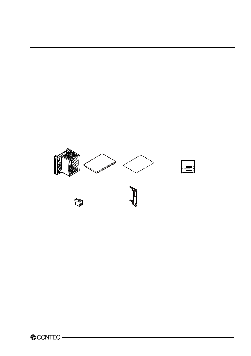
Check Your Package
Thank you for purchasing the CONTEC product. This product consists of the items listed below.
Check, with the following list, that your package is complete. If you discover damaged or missing items,
contact your retailer.
Product Configuration List
- Product [CPSN-MCB271-S1-041]…1
- Product Guide…1
- Warranty Certificate…1
- Serial Number Label…1
- Power Connector …1
- Blank panel…3
*This product is verified in conformity with our recommended power supply. In case you use other power supplies, thus, it may not be
able to fulfil certification requirements. Please see the Contec website regarding power supply recommendation.
CPSN-MCB271-S1-041 Reference Manual (Hardware)
i
Page 3

Copyright
Copyright 2018 CONTEC CO., LTD. ALL RIGHTS RESERVED.
No part of this document may be copied or reproduced in any form by any means without prior written
consent of CONTEC CO., LTD.
CONTEC CO., LTD. makes no commitment to update or keep current the information contained in this
document.
The information in this document is subject to change without notice.
All relevant issues have been considered in the preparation of this document. Should you notice an
omission or any questionable item in this document, please feel free to notify CONTEC CO., LTD.
Regardless of the foregoing statement, CONTEC assumes no responsibility for any errors that may
appear in this document or for results obtained by the user as a result of using this product.
Trademarks
This product is a registered trademark or trademark of CONTEC CO., LTD. Other company and
product names that are referred to in this manual are generally trademarks or registered trade trademark.
CPSN-MCB271-S1-041 Reference Manual (Hardware)
ii
Page 4

Table of Contents
Check Your Package ............................................................................................................................ i
Copyright ............................................................................................................................................ ii
Trademarks .......................................................................................................................................... ii
Table of Contents ............................................................................................................................... iii
1. Before Using the Product 1
About the Unit ..................................................................................................................................... 1
Hardware Features........................................................................................................................ 1
Software Features ......................................................................................................................... 2
How to use.................................................................................................................................... 2
Model details ................................ ................................................................ ................................ 3
Customer Support................................................................................................................................ 4
Limited Two-Year Warranty ............................................................................................................... 4
How to Obtain Service ........................................................................................................................ 4
Liability ............................................................................................................................................... 4
Safety Precautions ............................................................................................................................... 5
Safety Information ....................................................................................................................... 5
Handling Precautions .......................................................................................................................... 6
2. Setup 9
Setup Procedure .................................................................................................................................. 9
Installation ......................................................................................................................................... 10
Mounting on and Removing from the DIN Rail or the wall ...................................................... 10
Installation Conditions ............................................................................................................... 16
Installation and Removal of I/O module and blank panels ........................................................ 19
Inserting and Removing the microSD ........................................................................................ 21
Cable Connection .............................................................................................................................. 25
Cable Connection ....................................................................................................................... 25
Power.......................................................................................................................................... 26
LAN............................................................................................................................................ 26
RS-232C (COM) ........................................................................................................................ 27
Software Setup .................................................................................................................................. 28
3. Nomenclature and Functions 29
Nomenclature of Components ........................................................................................................... 29
Component Functions ....................................................................................................................... 30
Power Connector (12 - 24VDC) ................................................................................................. 30
LED ............................................................................................................................................ 31
RS-232C Interface (COM) ......................................................................................................... 32
CPSN-MCB271-S1-041 Reference Manual (Hardware)
iii
Page 5

Push Switch (SW) ...................................................................................................................... 33
USB Port (USB) ......................................................................................................................... 33
LAN Port (LAN) ........................................................................................................................ 34
Expansion slot ............................................................................................................................ 35
microSD Card Slot ..................................................................................................................... 35
4. System Reference 37
Specifications .................................................................................................................................... 37
Power Requirements................................................................................................................... 38
Physical Dimensions .................................................................................................................. 39
5. List of Optional Products 41
DIN rail fitting power supply ..................................................................................................... 41
I/O module.................................................................................................................................. 41
CPSN-MCB271-S1-041 Reference Manual (Hardware)
iv
Page 6

1 Before Using the Product
1. Before Using the Product
This chapter provides necessary information before using the product.
About the Unit
This product is a remote I/O model CPU unit that has RS-232C and LAN interfaces in addition to four
expansion slots. If necessary, you can freely combine this product with CONPROSYS nano series I/O
modules.
In addition, this product can be controlled from a PC running Windows or Linux and supports Modbus
TCP Slave and Modbus RTU Slave.
Hardware Features
I/O module expansion
With this product, you can freely add I/O modules to match the necessary functions from among the
varied collection of CONPROSYS nano series I/O modules.
Max. 921,600bps RS-232C Serial Communication
The Product has one RS-232C-standard serial port. Baud rates from 110 to 921,600 bps can be set.
Compact Design
Compact design, 110 (W) × 74.8 (D) × 95 (H) mm, features flexibility in installation.
Easy installation and removal of I/O modules
Expansion modules can be installed and removed without any tools.
Adaptable to a wide range of temperature between -20 and +60°C
The product is capable of operating in the temperature between -20 and + 60°C. It can be installed in the
various environments.
Installation easy with a two-piece terminal on DIN or with screws
Regarding the power connector, the terminal connector can be removed without a screwdriver. Even
when a malfunction occurs, this product can be replaced in a short length of time. Furthermore, as the
product is mounted on the DIN rail, removing and replacing are easy as well. This product can also be
installed with screws, so it supports a wide range of installation situations.
Equipped with the LED for an operation check
The product has the LED for an operation check, which helps you visually confirm the communication
status of each interface.
No electrolytic capacitor
The product has the LED for an operation check, which helps you visually confirm the communication
status of each interface.
CPSN-MCB271-S1-041 Reference Manual (Hardware)
1
Page 7
1 Before Using the Product
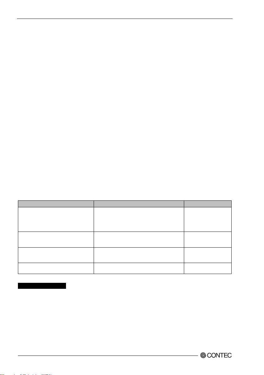
The name of the documents
Contents
How to get
Product Guide
This guide explains how to check the i tems
included with the product and the precautions
before using the product. The warranty is
included with this guide, so store it in a safe
place.
Come with the document.
(Printed matter)
Reference Manual f or I/O Module
(Hardware)
This manual explains items pertaining to the
hardware such as the I/O module's functions and
settings.
Download (PDF)
Reference Manual f or CPU Unit
(Hardware)
This manual explains items pertaining to the
hardware such as the CPU unit's functions and
settings.
Download (PDF)
Reference Manual f or CPU Unit
(Software)
This manual explains the settings of
"CONPROSYS nano WEB Setting".
Download (PDF)
Download
https://www.contec.com/download/
Software Features
Compatible with Modbus TCP Slave and Modbus RTU Slave
Modbus is a communication protocol widely adopted in the industrial sector.
Controlling and collecting data from higher-level devices with Modbus Master function can be
conducted.
Applicable with Windows driver software
The product supplies UDP/IP-based original protocol (F&eIT) and applications can be created with
Windows driver software in the Win32 API function format (DLL).
On top of that, you can check whether software and hardware are operating properly with the diagnostic
program.
Support the virtual COM driver
Software virtual COM driver enables you to operate the product in the same way as PC COM port
(standard COM). Applications can be created with the OS standard Win32 API communication
function.
How to use
Information regarding how to use this product is given in the CPSN-MCB271 Reference Manual
(Software), so check the System Setup Guide from the CONTEC website.
CPSN-MCB271-S1-041 Reference Manual (Hardware)
2
Page 8
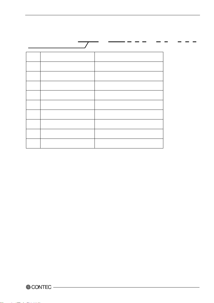
Model details
No
Item
Contents
1
Model
MCB: Standard Backplane Model
2
CPU
2: ARM Cortex M3
3
Memory
7: 16M Byte
4
Version
1: The 1st Model
5
Interface
S: Serial (RS-232C/RS-422/485)
6
Numbering of the Interface
1: The 1st Model
7
OS
0: Non OS
8
ROM
4:4MB
9
Application
1: Original version
CPSN - MCB 2 7 1 - S 1 - 0 4 1
1 2 3 4 6 8 9CONPROSYS nano Series 5 7
1 Before Using the Product
CPSN-MCB271-S1-041 Reference Manual (Hardware)
3
Page 9

1 Before Using the Product
Customer Support
CONTEC provides the following support services for you to use CONTEC products more efficiently
and comfortably.
Web Site
https://www.contec.com/
Latest product information
CONTEC provides up-to-date information on products.
CONTEC also provides product manuals and various technical documents in the PDF.
Free download
You can download updated driver software and differential files as well as sample programs in several
languages.
Note: For product information
Contact your retailer if you have any technical questions regarding a CONTEC product or need its price,
delivery time, or estimate information.
Limited Two-Year Warranty
CONTEC products are warranted by CONTEC CO., LTD. to be free from defects in material and
workmanship for up to two years from the date of purchase by the original purchaser.
Repair will be free of charge only when this device is returned freight prepaid with a copy of the
original invoice and a Return Merchandise Authorization to the distributor or the CONTEC group
office, from which it was purchased.
This warranty is not applicable for scratches or normal wear, but only for the electronic circuitry and
original products. The warranty is not applicable if the device has been tampered with or damaged
through abuse, mistreatment, neglect, or unreasonable use, or if the original invoice is not included, in
which case repairs will be considered beyond the warranty policy.
How to Obtain Service
For replacement or repair, return the device freight prepaid, with a copy of the original invoice. Please
obtain a Return Merchandise Authorization number (RMA) from the CONTEC group office where you
purchased before returning any product.
* No product will be accepted by CONTEC group without the RMA number.
Liability
The obligation of the warrantor is solely to repair or replace the product. In no event will the warrantor
be liable for any incidental or consequential damages due to such defect or consequences that arise from
inexperienced usage, misuse, or malfunction of this device.
CPSN-MCB271-S1-041 Reference Manual (Hardware)
4
Page 10
1 Before Using the Product
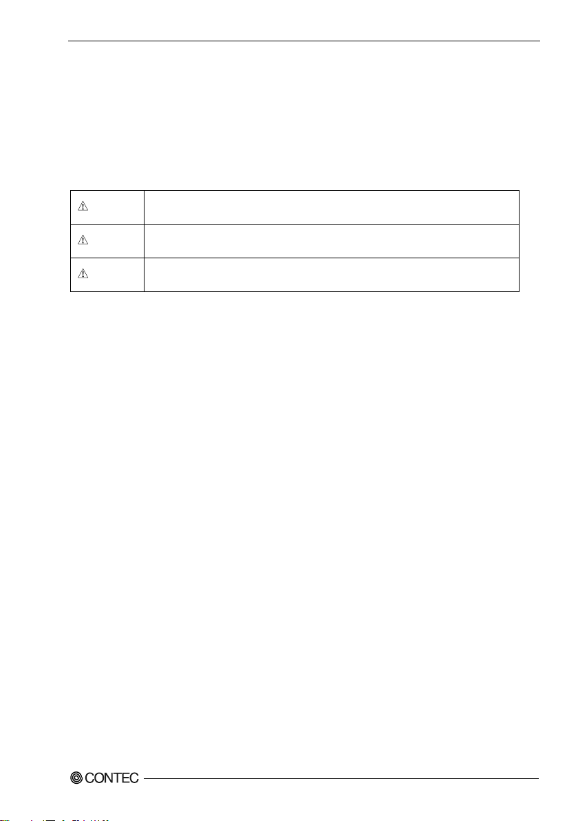
DANGER indicates an imminently hazardous situation which, if not avoided,
will result in death or serious injury.
WARNING indicates a potentially hazardous situation which, if not avoided,
could result in death or serious injury.
CAUTION indicates a potentially hazardous situation which, if not avoided,
may result in minor or moderate injury or in property damage.
DANGER
WARNING
CAUTION
Safety Precautions
Understand the following definitions and precautions to use the product safely.
Safety Information
This document provides safety information using the following symbols to prevent accidents resulting
in injury or death and the destruction of equipment and resources. Understand the meanings of these
labels to operate the equipment safely.
CPSN-MCB271-S1-041 Reference Manual (Hardware)
5
Page 11

1 Before Using the Product
DANGER
CAUTION
Handling Precautions
- Do not use the product in locations exposed to a flammable or corrosive gas. It may cause
explosion, fire, electrical shock, or malfunction.
- Do not allow the device to come into contact with foreign substances (metal particles, flammable
substances, liquids, etc.) Otherwise, it can cause fire or electrical shock.
- Do not place the product in an unstable location or use incomplete mountings. Otherwise, it may
cause the device to fall.
- Be sure to connect the product to the stipulated power supply voltage. Connecting to a different
voltage might cause a fire or electrical shock.
- If the product is used in a manner not specified by the manufacturer, the protection provided by the
equipment may be impaired.
- The product is not intended for use in aerospace, space, nuclear power, medical equipment, or other
applications that require a very high level of reliability. Do not use the product in such applications.
- If using the product in applications where safety is critical such as in railways, automotive, or
disaster prevention or security systems, please contact your retailer.
- Be certain the following requirements are satisfied when using the product.
- Indoor use
- Altitude up to 5000m
- Applicable POLLUTION DEGREE 2
When using the product at high altitudes, refer to the relational expression below to find an
appropriate ambient temperature. The heat dissipation decreases due to air pressure drop and could
lead to damages or a shorter product life.
- Ambient temperature = 60[°C] - 0.005 x altitude [m]
An Example) The product is used at 3000 meters
60°C - (0.005 x 3000m) = 45°C (Ambient temperature)
- Do not use or store the product in a location exposed to extremely high or low temperature that
exceeds range of specification or susceptible to rapid temperature changes.
e.g. - Exposure to direct sun
- In the vicinity of a heat source
- Do not use the product in extremely humid or dusty locations. It is extremely dangerous to use the
product with its interior penetrated by water or any other fluid or conductive dust. If the product
must be used in such an environment, install it on a dust-proof control panel, for example.
- Avoid using or storing the product in locations subject to shock or vibration that exceeds range of
specification.
- When transporting the product, take suitable measures to avoid applying shock or vibration directly
to the product. Impact resistance: 15G (11ms) below.
- Use the product in the specified operating condition (temperature, humidity, vibration and shock).
CPSN-MCB271-S1-041 Reference Manual (Hardware)
6
Page 12

1 Before Using the Product
- Avoid installing in the place where ventilation of the product may compromise. Insufficient
aeration could heat up the product and lead to malfunctions or damages.
- Do not use the product in the vicinity of devices that generate strong magnetic force or noise. Such
products will cause the product to malfunction (stop, reboot).
- Do not use or store the product in the presence of chemicals.
- When removing connectors or cables, always unplug the power cable of CPU unit and confirm the
LEDs are turned off.
- Do not modify the product. CONTEC will bear no responsibility for any problems, etc., resulting
from modifying the product.
- In the event of failure or abnormality (foul smells or excessive heat generation), unplug the power
cable of CPU unit immediately and contact your retailer.
- When using the product in an overly noisy environment, use a grounded, shielded cable to connect
with peripherals.
- To clean the product, wipe it gently with a soft cloth dampened with either water or mild detergent.
Do not use chemicals or a volatile solvent, such as benzene or thinner, to prevent the paint to be
scraped or discolored.
- When connecting cables, first check the shapes of connectors, and then insert them in the correct
orientation. After they are connected, do not put too much load on the connected part. Doing so
may result in poor contact or damage to the product and the connected part.
- Do not touch metal parts or terminals with your hands when the product is in operation. Otherwise,
the product may malfunction, or cause failure.
- Do not touch the front panels with your hands when the product is in operation. Otherwise, the
product may malfunction or cause failure.
- Do not touch the product or connectors with a wet hand to avoid electric shock.
- The specifications of the product are subject to change without notice for enhancement and quality
improvement. Even when using the product continuously, be sure to read the manual in the
CONTEC’s website and understand the contents.
- When the product is used in a place that is affected by overcurrent or overvoltage (lightning surge),
select appropriate surge protection device for all of the route (Signal line, etc.). Consult with the
specialist regarding selecting, purchasing, and setting the surge protection device.
- The product is an open-type device (a device designed to be housed inside other equipment) and
must always be mounted inside a mechanical enclosure having enough strength.
- Do not strike or bend this product. Otherwise, this product may malfunction, overheat, cause a
failure or breakage.
- Do not touch this product's metal plated terminals (edge connector) with your hands. Otherwise,
this product may malfunction, overheat, or cause a failure. If the terminals are touched by
someone's hands, clean the terminals with industrial alcohol.
- Always install the blank panels into vacant slots while power is active.
- Regarding “CE EMC Directive Notice”.
Please connect the Interface Connector with a shielded cable to meet the mentioned standard above.
CPSN-MCB271-S1-041 Reference Manual (Hardware)
7
Page 13
1 Before Using the Product
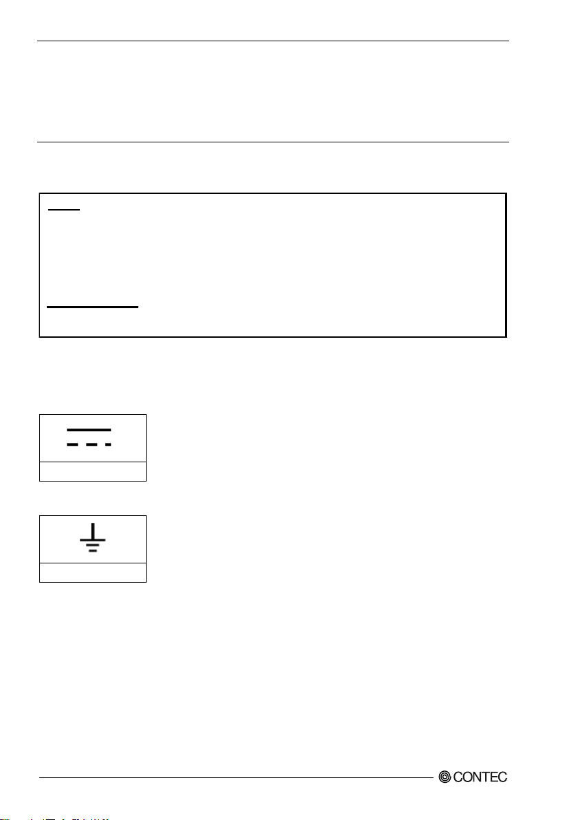
DC power supply
Functional earth terminal
This equipment has been tested and found to comply with the limits for a Class A digital device,
pursuant to part 15 of the FCC Rules. These limits are designed to provide reasonable protection
against harmful interference when the equipment is operated in a commercial environment.
This equipment generates, uses, and can radiate radio frequency energy and, if not installed and
used in accordance with the instruction manual, may cause harmful interference to radio
communications. Operation of this equipment in a residential area is likely to cause harmful
interference in which case the user will be required to correct the interference at his own expense.
NOTE
FCC WARNING
Changes or modifications not expressly approved by the party responsible for compliance could void
the user's authority to operate the equipment.
- When disposing of the product, follow the disposal procedures stipulated under the relevant laws
and municipal ordinances.
- Regardless of the foregoing statements, CONTEC is not liable for any damages whatsoever
(Including damages for loss of business profits) arising out of the use or inability to use this
CONTEC product or the information contained herein.
FCC PART15 Class A Notice
EN55032 Class A Notice
Warning: Operation of this equipment in a residential environment could cause radio interference.
Display of power (Input Rating Label)
Functional earth terminal
CPSN-MCB271-S1-041 Reference Manual (Hardware)
8
Page 14

2. Setup
Setup Procedure
Follow the steps below to set up.
STEP1 Installation procedure
Proceed accordingly with the instruction to set up the product correctly.
STEP2 Cable connection
STEP3 Turning on the power.
Reconfirm that you have correctly followed steps 1and 2. Then, turn on the power.
If you find any errors or abnormalities after turning on the power, turn it off immediately
and check whether the setup has been properly conducted.
2 Setup
CPSN-MCB271-S1-041 Reference Manual (Hardware)
9
Page 15
2 Setup
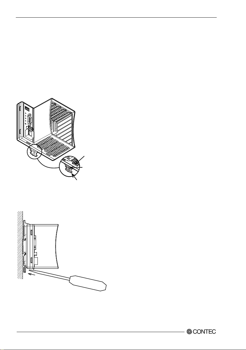
Projection Tip
Screwdriver insertion hole
DIN rail fixed hook
Installation
Mounting on and Removing from the DIN Rail or the wall
Before mounting the product on the DIN rail, you need to unlock the fixed hook of the product.
If you plan to mount the product on the wall, appropriate commercial screws are necessary.
Unlock a fixed hook
(1) Insert a slotted screwdriver (the point should be smaller than 7mm) into a hole.
(see the figure below)
Figure 2.1. Unlocking the fixed hook < 1 / 3 >
Figure 2.2. Unlocking the fixed hook < 2 / 3 >
(2) By using the screwdriver as leverage, move it upward in the direction of the arrow to unlock.
CPSN-MCB271-S1-041 Reference Manual (Hardware)
10
Page 16

Figure 2.3. Unlocking the fixed hook < 3 / 3 >
2 Setup
CPSN-MCB271-S1-041 Reference Manual (Hardware)
11
Page 17

2 Setup
Mount on the DIN Rail
(1) Pull down the fixed hook at the bottom to unlock.
Figure2.4. Mounting on the DIN Rail < 1 / 3 >
(2) Hang the product on the upper part of the DIN rail, and press it to the lower side of the DIN rail.
Figure2.5. Mounting on the DIN Rail < 2 / 3 >
CPSN-MCB271-S1-041 Reference Manual (Hardware)
12
Page 18

(3) Push up the hook to lock.
CAUTION
Figure2.6. Mounting on the DIN Rail < 3 / 3 >
Confirm whether the product has been securely mounted onto the DIN rail.
2 Setup
CPSN-MCB271-S1-041 Reference Manual (Hardware)
13
Page 19

2 Setup
Remove from the DIN Rail
(1) Pull down the fixed hook at the bottom to unlock.
Figure 2.7. Removing from the DIN Rail < 1 / 2 >
(2) Pull the lower part of the product toward you and lift it up.
e
Figure 2.8. Removing from the DIN Rail < 2 / 2 >
CPSN-MCB271-S1-041 Reference Manual (Hardware)
14
Page 20

Mounting on the wall
CAUTION
(1) Use the three M3 screws to mount the product on the wall.
(2) The tightening torque should be within 6 kgf·cm.
The excessive torque could damage the product.
(3) When using the helical spring lock washers, use the ones with the diameter smaller than 8mm.
2 Setup
Figure 2.9. Mounting on the wall
Confirm whether the product has been securely mounted onto the wall.
CPSN-MCB271-S1-041 Reference Manual (Hardware)
15
Page 21

2 Setup
PWR
V+V-
RUN
STS
ERR
SW
LINK/AC T
SPEED
PWR
V+V-
RUN
STS
ERR
SW
LINK/AC T
SPEED
(Top)
(Under)
(Top)
(Bottom)
Installation Conditions
Installation orientation
You can position the product in the orientation shown below.
Other orientations could cause problems such as malfunction due to inadequate heat dissipation.
Vertical installation (Installation angle 0°)
Figure 2.10. Installation orientation (Installation angle 0°)
Vertical installation with an angle of 90° to the right/left (Installation angle: 90° to the right/left;
only installations in which the product is screwed in are supported)
Figure 2.11. Installation orientation (Installation angle: 90° to the right/left; only installations in
which the product is screwed in are supported)
CPSN-MCB271-S1-041 Reference Manual (Hardware)
16
Page 22

2 Setup
CAUTION
Horizontal installation
Figure 2.12. Installation orientation (Horizontal)
Make sure to gain proper space between the product and devices that generate heat or exhaust air so that
the ambient temperature stays in the range specified in the environment requirement.
Also, the temperature range in the environment requirements varies depending on the
installation orientation, so check the operating temperature range in "Chapter 4 System
Reference".
Recommended installation angle
The recommended installation angle for this product is 0°. The temperature specifications of the product
vary between the case when the installation angle is 90° to the left/right and the case when a plane
installation is used, so check the operating temperature range in "Chapter 4 System Reference".
Ambient temperature
The ambient temperature is decided from the multiple measurement points which are a 50mm-distance
from the case. During the operation, adjust the air current to make certain that the temperatures
measured in the points stay within the specified temperature.
- The product is an open-type device (a device designed to be housed inside other equipment) and
must always be mounted inside a mechanical enclosure having enough strength.
- Note that although the ambient temperature is within the specified range, an operational failure may
occur if there is other device generating high heat nearby; the radiation will influence the product to
increase its temperature.
- Do not install the product into the fully-sealed space except the case in which the internal
temperature is adjustable by equipment such as an air conditioner. Long-term usage might increase
the temperature and lead to a malfunction or other troubles.
- When using the product in a high temperature environment, its life time will be shorten. Perform
the forced air cooling to counteract.
CPSN-MCB271-S1-041 Reference Manual (Hardware)
17
Page 23

2 Setup
50 50
50
50
50
[m m]
Measurement points
Spaces between the product and surrounding objects (Exemplar)
Figure 2.13. Distances between the product and its vicinity (Exemplar)
CPSN-MCB271-S1-041 Reference Manual (Hardware)
18
Page 24

Installation and Removal of I/O module and blank panels
CAUTION
The groove is
on the right.
The hook is
on the left.
Always confirm the PWR-LED is turned off before installing or removing the module.
Installation procedure
(1)
Paying attention to the horizontal orientation of the I/O module, insert the resin
groove into the rail of the CPU unit that has been installed on a DIN rail or that has
been screwed into place, and then push the I/O module in until it clicks.
2 Setup
Figure 2.14. Installing the I/O module and blank panels
CPSN-MCB271-S1-041 Reference Manual (Hardware)
19
Page 25

2 Setup
Removal procedure
(1)
Press in the hooks at the top and bottom of the I/O module, and then pull it toward
you and out of the CPU unit that has been installed on a DIN rail or that has been
screwed into place.
Figure 2.15. Removing the I/O module and blank panels
CPSN-MCB271-S1-041 Reference Manual (Hardware)
20
Page 26

Inserting and Removing the microSD
CAUTION
Always confirm the PWR-LED is turned off before inserting or removing the microSD.
- Inserting procedure
(1) Slide down the cover of microSD socket.
2 Setup
Figure 2.16. Inserting the microSD<1/5>
(2) Open the cover up.
Figure 2.17. Inserting the microSD <2/5>
CPSN-MCB271-S1-041 Reference Manual (Hardware)
21
Page 27

2 Setup
(3) Insert the microSD card into the cover.
Figure 2.18. Inserting the microSD <3/5>
(4) Close the cover.
Figure 2.19. Inserting the microSD <4/5>
(5) Slide the cover up to lock it in place.
Figure 2.20. Inserting the microSD <5/5>
CPSN-MCB271-S1-041 Reference Manual (Hardware)
22
Page 28

- Removing procedure
(1) Slide down the cover of microSD socket.
2 Setup
Figure 2.21. Removing the microSD<1/5>
(2) Open the cover up.
Figure 2.22. Removing the microSD<2/5>
(3) Remove the microSD card from the cover.
Figure 2.23. Removing the microSD <3/5>
CPSN-MCB271-S1-041 Reference Manual (Hardware)
23
Page 29

2 Setup
(4) Close the cover.
Figure 2.24. Removing the microSD <4/5>
(5) Slide the cover up to lock it in place.
Figure 2.25. Removing the microSD <5/5>
CPSN-MCB271-S1-041 Reference Manual (Hardware)
24
Page 30

2 Setup
CAUTION
Cable Connection
Cable Connection
Regarding connection
When connecting the product to an external device, use the supplied connector plug.
For wiring connector, strip off the covered part of a wire rod (8mm ± 0.5mm) and insert it to the
opening.
While pressing the orange part in the center of the connector with a precision screwdriver or a similar
tool, insert the cable into the round hole. After that, release the pressed part to fix the cable in place.
Removing the connector plug by grasping the cable can break the wire.
About a caution mark on the product:
Use copper wires that tolerate the temperature of 75 degrees Celsius and higher.
Figure 2.26. Cable connection
CPSN-MCB271-S1-041 Reference Manual (Hardware)
25
Page 31

2 Setup
CAUTION
Power
Power Cable
Use the power cable described below.
- Cable : Twisted pair cable (when using a single wire, twist V+ wire and V- wire)
- Cable Diameter : AWG20-16 (0.5mm2 -1.25mm2)
- Cable Length : within 3 meters
FG Cable
Use the FG cable described below.
- Cable Diameter : AWG18-16 (0.75mm2 -1.25mm2)
Specification of external power supply
This product is designed to operate with 30 watt power supply depending on the number of configurable
modules.
In addition, the power supply must fulfill the following requirements.
- Rising time for up to 24 voltage: 2 milliseconds up till 30 milliseconds
Recommended power supply is CPS-PWD-30AW24-01 (by CONTEC).
- If the maximum output current of the external power supply is smaller than the maximum
consumption current of this product, the abnormal operations might occur due to the inrush current
at the start-up time or the load fluctuation. The aging external power supply could cause a start-up
failure.
- About a caution mark on the product:
Please use copper wires that tolerate the temperature of 75 degrees Celsius and higher.
LAN
Use the LAN cable described below.
- Category : Category 5 or more
- Cable Length : within 100 meters
CPSN-MCB271-S1-041 Reference Manual (Hardware)
26
Page 32

2 Setup
RS-232C (COM)
When using an RS-232C interface, different cables may be required depending on the types of device to
which you are connecting (computer or modem, etc.). Check the requirements of the external device and
select either a straight-through or crossed (null modem) cable as appropriate. If special treatment of the
signal lines in the connector is required, ensure that this is done in accordance with the specifications.
Figure 2.27. Example connection to a modem
Figure 2.28. Example connection to a PC
Figure 2.29. Example connection to a device
CPSN-MCB271-S1-041 Reference Manual (Hardware)
27
Page 33

2 Setup
Baud Rate(bps)
Error(%)
110
0.000%
134.5
0.372%
150
0.000%
300
0.000%
600
0.000%
1200
0.000%
1800
0.000%
2000
0.071%
2400
0.000%
3600
0.000%
4800
0.000%
7200
0.000%
9600
0.000%
14400
0.000%
19200
0.001%
28800
0.006%
38400
0.012%
57600
0.023%
76800
0.016%
115200
0.032%
153600
0.016%
230400
0.059%
460800
0.059%
921600
0.059%
See the table below for baud rate that you can set with this product.
Table 2.1. Baud Rate List
Software Setup
Information on the software setup is given in the CPSN-MCB271 Reference Manual (Software), so
check that manual.
CPSN-MCB271-S1-041 Reference Manual (Hardware)
28
Page 34

3 Nomenclature and Functions
PWR
V+V-
RUN
STS
ERR
SW
LINK/AC T
SPEED
①
②
③
④
⑤
⑥
⑦
⑧
⑨
3. Nomenclature and Functions
Nomenclature of Components
Component names of the products are shown in Figure 3.1 and Figure 3.2.
Figure 3.1. CPSN-MCB271-S1 -041 Nomenclature of components
(1) Power Connector : Use the power connector (3 pin connector), included in this package.
(2) LED : Indicates the status of the product.
(3) RS-232C : It is a RS-232C serial ports (male).
(4) Switch : This is used with the software setup.
(5) USB : It is a USB port.
(6) LAN : It is a connector for LAN.
(7) Expansion slot : These are used to supply power to and communicate with expansion modules.
(8) microSD Card Slot : It is for data storage.
(9) Jumper : Please do not use it.
CPSN-MCB271-S1-041 Reference Manual (Hardware)
29
Page 35

3 Nomenclature and Functions
Pin No
Signal name
Meaning
1
FG
Frame ground
2
V-
Power supply (GND)
3
V+
Power supply (12 - 24VDC)
1 2 3
Component Functions
Power Connector (12 - 24VDC)
Use the 3-pin connector, included in this package.
Connector type : DEGSON 15EDGKD-3.5-03P-13-00A(H) (or equivalent)
Table 3.1. Power connector
CPSN-MCB271-S1-041 Reference Manual (Hardware)
30
Page 36

3 Nomenclature and Functions
LED
Operation
Meaning
PWR(Green)
ON
Initialization is complete.
OFF
No power supplied.
Flashing
Initialization is in progress.
Continuous
flashing
(twice)
An initialization error occurred.
Continuous
flashing
(three times)
A firmware writing error occurred.
RUN(Green)
ON
The firmware is operating.
OFF
The product is operating in recovery mode.
Flashing
The recording media (USB, SD) is being accessed.
STS(Green)
ON
An I/O module is connected.
OFF
No I/O modules are connected.
Flashing
An I/O module is being accessed correctly.
ERR(Red)
ON
This lights when a system error occurs.
- An I/O module cannot be recognized correctly.
- An error occurred while accessing an I/O module.
OFF
This is off when there are no system errors.
PWR(Green)
RUN(Green)
STS(Green)
All flashing
at the same time
Data is being written to the firmware or the setup file.
LED
This product is equipped with LEDs (PWR [power], RUN, STS [status], and ERR [error]) that indicate
the status.
Table 3.2. LED
CPSN-MCB271-S1-041 Reference Manual (Hardware)
31
Page 37

3 Nomenclature and Functions
Pin No.
Signal
name
Direction
Meaning
1
CD
Input
Carrier detection
2
RD
Input
Received data
3
TD
Output
Transmitted data
4
DTR
Output
Data terminal ready
5
GND
-----
Signal ground
6
DSR
Input
Data set ready
7
RTS
Output
Request to send
8
CTS
Input
Clear to send
9
RI
Input
Ring indicate
1
5
6
9
No.4-40UNC
Inch nut
RS-232C Interface (COM)
This product has 1port of RS-232C compliant serial ports of a baud rate 921,600bps (Maximum).
Table 3.3. Serial Ports connector
CPSN-MCB271-S1-041 Reference Manual (Hardware)
32
Page 38

3 Nomenclature and Functions
Pin No.
Signal Name
1
USB_VCC
2
DATA-
3
DATA+
4
USB_GND
41
Push Switch (SW)
This controls the product's power supply.
Start in recovery mode: Use this procedure if you need to recover the product when the firmware is
corrupted.
(Procedure)
(1) While holding down the push switch, turn the power ON.
(2) When PWR (green LED) lights and RUN (green LED) turns off, the product starts operating in
recovery mode.
Setup information initialization: Use this procedure to initialize the setup information.
(Procedure)
(1) When the initialization is finished, press the push switch.
(2) PWR (green LED), RUN (green LED), and STS (green LED) start to flash.
(3) These LEDs will flash for 3 seconds, so release the push switch while the LEDs are flashing.
(4) Wait for PWR (green LED), RUN (green LED), and STS (green LED) to stop flashing.
(5) When PWR (green LED), RUN (green LED), and STS (green LED) return to their original statuses,
the initialization is complete.
USB Port (USB)
The product has 1 port of USB interface of TYPE-A.
Table 3.4. USB connector
CPSN-MCB271-S1-041 Reference Manual (Hardware)
33
Page 39

3 Nomenclature and Functions
Pin No.
Signal Name
Meaning
1
TX+
Transmission data(+)output
2
TX-
Transmission data (-)output
3
RX+
Received data (+)input
4
N.C.
Not connected
5
N.C.
Not connected
6
RX-
Received data (-)input
7
N.C.
Not connected
8
N.C.
Not connected
LED
Operation
Meaning
Link /Act(Green)
ON
Indicates that LAN port is connected.
Flashing
Indicate that LAN port is transmitting and receiving data with the
connected externa l device.
OFF
Indicates that LAN port is not connected.
Speed(Orange)
ON
Indicates that LAN port is connected by 100Mbps.
OFF
Indicates that LAN port is connected by 10Mbps or not connected.
8
1
Link/Act
Speed
LAN Port (LAN)
This product have 1 port of Ethernet.
- Network type : 10BASE-T/100BASE-TX
- Transmission speed : 10M/100M bps
- Maximum network path length : 100m /segment
Table 3.5. LAN port
Table 3.6. LED indicator (Side, LAN ports)
CPSN-MCB271-S1-041 Reference Manual (Hardware)
34
Page 40

3 Nomenclature and Functions
CAUTION
Expansion slot
This product has four I/O slots in which you can install I/O modules.
These slots are used to supply power to and communicate with the I/O modules.
Do not install or remove I/O modules while power is being supplied to this product.
Be sure to check that the LEDs on the main unit are off before installing or removing modules.
microSD Card Slot
The product is equipped with one microSD card slot.
CPSN-MCB271-S1-041 Reference Manual (Hardware)
35
Page 41

3 Nomenclature and Functions
CPSN-MCB271-S1-041 Reference Manual (Hardware)
36
Page 42

4. System Reference
Item
CPSN-MCB271-S1-041
CPU
ARM Cortex-M3 180MHz
Memory
On Board 16MB SDRAM
ROM
On-Board 4MB NOR Flash for OS
FeRAM
On-Board 32kB
LAN
Transmission standard
10BASE-T/100BASE-TX
The number of channels
1ch
Connector
RJ-45 Connector
LED
Speed(Orange), Link / Act(Green)
USB
Transmission standard
USB2.0 standard follow
The number of channels
1ch
Connector
TYPE-A
microSD Card slot
Standard
SD standard follow
Connector
microSD memory card slot
RS-232C
Baud Rate
110 - 921.6kbps
Data length
5, 6, 7, 8 bit 1, 1.5, 2 stopbit
Parity check
Even, Odd, Non-parity
The number of channels
1ch
Isolation
Non-isolated
Connector
9-pin D-SUB Connector (Male)
Expansion slot
Number of slots
4
Maximum power supply
24V 200mA, 5V 250mA, 3.3V 200mA (per slot)
Number of
insertions/removals
50 times (min)
LED
PWR(Green) / RUN( Green) / STS(Green) / ERR(Red)
Switch
Push switch
RTC
Monthly error
±15 seconds or less (25°C)
Backup time
-
Power supply *1
Rated input voltage
12 - 24VDC
Input voltage range
10.8 - 30VDC
Power consumption
24V 0.08A (Typ.)*2, 1.5A (Max.)
12V 0.15A (Typ.)*2, 2.0A (Max.)
Connector
2 pieces 3.5mm pitch 3-pin Terminal (V+, V-, FG)
Applicable wire
AWG20 - 16
Surge protection element
V+ - V-, V- - FG
Interactive TVS Diode
Stand off voltage : ±30V, Peak pulse power : 400W (1ms)
Physical dimensions (mm)
110(W)×74.8(D)×95(H)mm (not include projection)
Weight
250g
Installation method
Quick installation on a 35 mm DIN rail
Vertical installation with screws *3
Specifications
Table 4.1. Function specifications <1/2>
4 System Reference
*1 Use power cable within 3meters.
*2 With no USB load and no expansion slot load
*3 Commercially available screws are required.
CPSN-MCB271-S1-041 Reference Manual (Hardware)
37
Page 43

4 System Reference
Item
CPSN-MCB271-S1-041
Operating ambient temperature
-20 to +60°C *1
Operating ambient humidity
10 to 90%RH (No condensation)
Non-operating ambient temperature
-20 to +60°C *4
Non-operating ambient humidity
10 to 90%RH (No condensation)
Floating dust particles
Not to be excessive
Corrosive gases
None
Line-noise
resistance
Line noise
AC Line/±2kV *2
Signal Line/±1kV (IEC61000-4-4 Level 3, EN61000-4-4 Level 3)
Static electricity resistance
Touch/±4kV (IEC61000-4-2 Level 2, EN61000-4-2 Level 2)
Air/±8kV (IEC61000-4-2 Level 3, EN61000-4-2 Level 3)
Vibration
resistance
Sweep resistance
10 - 57Hz*3 / semi-amplitude vibration 0.15mm, 57 - 150Hz / 2.0G
40 minutes each in X, Y, and Z directions
(JIS C60068-2-6-compliant, IEC60068-2-6-compliant)
Shock resistance
15G half-sine shock for 11ms in X, Y, and Z directions (JIS C60068-227-compliant, IEC60068-2-27-complian t)
Impact resistance
Class D grounding (previous class 3 grounding),
SG-FG/ non-conduction
Standard
VCCI Class A, FCC Class A,
CE Marking (EMC Directive Class A, RoHS Directive)
CAUTION
Table 4.2. Installation Environment Requirements
*1 -20°C to +55°C with a vertical installation at an angle of 90° to the left/right or with a plane installation
*2 When you use the CPS-PWD-30AW24-01 (optional product)
*3 When you use an optional power product: 10-55Hz (See the manual of optional power product for details)
Power Requirements
System requires a clean, steady power source for reliable performance of the high frequency CPU on the
product, the quality of the power supply is even more important.
- If the fluctuation of power supply voltage is beyond the product specifications, connect a constant
voltage transformer.
- If the noise is large, connect an isolation transformer (a noise cut transformer).
- Never bundle, place nearby or in parallel the power supply cable and the input /output signal lines.
- If lightning surge protection is required, connect the surge protective device (SPD).
- Ground this product and the surge protective device (SPD) well away from each other.
- Please select the ones which do not exceed the maximum allowable circuit voltage for the surge
protective device (SPD) at the rise time of the power supply voltage.
- Before you restart the power, give the product for at least one second (or more) of the power OFF
time after PWR-LED is turned off.
- When you use with the CPS-PWD-30AW24-01 (by CONTEC), instantaneous voltage drop allowed
time will be 20 millisecond or less.
CPSN-MCB271-S1-041 Reference Manual (Hardware)
38
Page 44

4 System Reference
Physical Dimensions
Figure 4.1. Physical dimensions
CPSN-MCB271-S1-041 Reference Manual (Hardware)
39
Page 45

4 System Reference
CPSN-MCB271-S1-041 Reference Manual (Hardware)
40
Page 46

5. List of Optional Products
5 List of Optional Products
DIN rail fitting power supply
- CPS-PWD-30AW24-01 : DIN rail fitting power supply 30[w]
I/O module
- CPSN-DI-08L : with digital input (input 8 channels, No built-in power supply)
- CPSN-DI-08BL : with digital input (input 8 channels, built-in power supply)
- CPSN-DI-08L : with digital output (output 8 channels, No built-in power supply)
- CPSN-DI-08BL : with digital output (output 8 channels, built-in power supply)
- CPSN-AI-1208LI : with analog input
- CPSN-COM-1PD : with RS-422A/485 (1channel)
* Visit the Contec website regarding information on the optional products.
(Input: 100 - 240VAC, output: 24VDC 1.3 A)
CPSN-MCB271-S1-041 Reference Manual (Hardware)
41
Page 47

MONTH YEAR
Summary of Changes
January 2018
The First Edition
Revision History
CPSN-MCB271-S1-041
Reference Manual (Hardware)
CONTEC CO., LTD. January 2018 Edition
3-9-31, Himesato, Nishiyodogawa-ku, Osaka 555-0025, Japan
https://www.contec.com/
No part of this document may be copied or reproduced in any form by any means without prior written
consent of CONTEC CO., LTD. [01122018]
[01122018] Management No. NA05978
Parts No. LYVQ151
 Loading...