

Page 1

1COM-2(PCI)H,4(PCI)H,8(PCI)H
www.co ntec.co m
Ver.3.30
RS-232C Serial I/O Board for PCI 2ch
COM-2(PCI)H
RS-232C Serial I/O Board for PCI 4ch
COM-4(PCI)H
RS-232C Serial I/O Board for PCI 8ch
COM-8(PCI)H
Product Configuration List
- Board
[COM-2(PCI)H, COM-4(PCI)H or COM-8(PCI)H]
- First step guide…1
- COM Setup Disk(CD-ROM *1 ) …1
*1: The CD-ROM contains the driver software and User's Guide.
This board is a PCI bus interface board for performing RS-232C
serial communications with external devices.
The <COM-2(PCI)H> has two serial ports per board.
The <COM-4(PCI)H> has four serial ports per board.
The <COM-8(PCI)H> has eight serial ports per board.
You can use the standard COM driver software (COM Setup Disk)
supplied with the board to access the serial ports as standard
Windows or Linux COM ports.
The COM-2/4/8(PCI)H boards are backward compatible with the
CONTEC COM-2/4/8(PCI) boards. The COM-x(PCI)H can
therefore replace the COM-x(PCI) in an existing system.
Features
- Maximum communication speed = 921,600bps.
- The baud rate can be set independently for each channel, by
software.
- Each channel is equipped with separate 128-byte FIFO buffers for
transmit and receive.
- A maximum of 16 boards can be installed as configured in the range
COM1 - COM256.
- Driver software is supplied to allow the serial ports to be used as
standard Windows or Linux COM ports.
- The boards use the same easy-to-use 9-pin D-SUB connectors as
are used on a PC.
Cable & Connector (Option)
RS-232C Straight Cable with D-SUB9P (1.8m) : RSS-9M/F
RS-232C Cross Cable with D-SUB9P (1.8m) : RSC-9F
RS-232C Straight Cable with D-SUB25P (1.8m) : RSS-25M/F
RS-232C Cross Cable with D-SUB25P (1.8m) : RSC-25F
RS-232C Connection Conversion Straight Cable (25M 9F, 1.8m)
: RSS-25M/9F
RS-232C Connection Conversion Straight Cable (25F 9M, 1.8m)
: RSS-25F/9M
RS-232C Connection Conversion Cross Cable (25F 9F, 1.8m)
: RSC-25F/9F
Connection Conversion Cable (37M 9M x 4, 250mm)
: PCE37/9PS
Connection Conversion Cable (37M 25M x 4, 250mm)
: PCE37/25PS
Connection Conversion Cable for RS-232C (37M 25M x 4, 450mm)
: COM-4MCABLE(PC)1
Connection Conversion Cable (78M 9M x 8, 1m)
: PCE78/9PS
Connection Conversion Cable (78M 25M x 8, 1m)
: PCE78/25PS
COM-8ch Board Optional Cable for CCU-78F/25M (2m)
: RSS-78M
COM-4ch Board Optional Cable for CCU-78F/25M (2m)
: RSS-78M/37M
Set of five 9-pin D-SUB (male) connectors : CN5-D9M
Set of five 9-pin D-SUB (female) connectors : CN5-D9F
Set of five 25-pin D-SUB (male) connectors : CN5-D25M
Set of five 25-pin D-SUB (female) connectors : CN5-D25F
Set of five 37-pin D-SUB (male) connectors : CN5-D37M
Set of five 78-pin D-SUB (male) connectors : CN5-D78M
Accessories (Option)
Connection Conversion Unit for RS-232C(78P 25P x 8)
: CCU-78F/25M *1
*1 The option cable RSS-78M or RSS-78M/37M is needed.
The specification, color, and design of a product may be changed without a preliminary announcement.
Page 2
2COM-2(PCI)H,4(PCI)H,8(PCI)H
www.co ntec.co m
Ver.3.30
Specification
COM-2(PCI)H
Item Specification
Number of channels 2 channels
Interface type RS-232C
Transfer method Asynchronous serial transfer
Baud rate 2 - 921,600bps *1 *2
Data length 5, 6, 7, 8 bits
1, 1.5, 2 stop bits *1
Parity check Even, Odd, Non-parity *1
Controller chip 162850 or equivalent
(Each channel has 128-byte receive and 128-byte transmit FIFO buffers.)
Connecting distance 15m(Typ.)
Interrupt requests 1 level use *3
I/O address Any 32-byte boundary
Power consumption 3.3VDC 100mA (Max.) (JP1 pins 1 and 2 connected) *4
5VDC 100mA (Max.) (JP1 pins 2 and 3 connected) *4
Operating
temperature
0 - 50°C, 10 - 90RH (No condensation)
PCI bus specification 32-bit, 33MHz, Universal key shapes supported *4
Dimension (mm) 121.69(L) x 105.68(H) *4
Weight 100g
*1 These items can be set by software.
For the "API Function Library API-PAC(W32)" and the "Standard COM Driver Software
COM Setup Disk" on the supplied CD-ROM, the range is 15 - 921,600 bps.
*2 Data transmission at high speed may not be performed normally depending on the
environment including the type of status of connected material of cable and environment.
*3 The interrupt signals from individual channels are arranged into a single interrupt signal
and connected to the PCI bus.
*4 Boards with different board numbers are different in these specifications. See Table 6.4
"Different in the specification" at the end of this document.
COM-4(PCI)H
Item Specification
Number of channels 4 channels
Interface type RS-232C
Transfer method Asynchronous serial transfer
Baud rate 2 - 921,600bps *1 *2
Data length 5, 6, 7, 8 bits
1, 1.5, 2 stop bits *1
Parity check Even, Odd, Non-parity *1
Controller chip 162850 or equivalent
(Each channel has 128-byte receive and 128-byte transmit FIFO buffers.)
Connecting distance 15m(Typ.)
Interrupt requests 1 level use *3
I/O address Any 32-byte boundary
Power consumption 3.3VDC 150mA (Max.) (JP1 pins 1 and 2 connected) *4
5VDC 150mA (Max.) (JP1 pins 2 and 3 connected) *4
Operating
temperature
0 - 50°C, 10 - 90RH (No condensation)
PCI bus specification 32-bit, 33MHz, Universal key shapes supported *4
Dimension (mm) 121.69(L) x 105.68(H) *4
Weight 130g
*1 These items can be set by software.
For the "API Function Library API-PAC(W32)" and the "Standard COM Driver Software
COM Setup Disk" on the supplied CD-ROM, the range is 15 - 921,600 bps.
*2 Data transmission at high speed may not be performed normally depending on the
environment including the type of status of connected material of cable and environment.
*3 The interrupt signals from individual channels are arranged into a single interrupt signal
and connected to the PCI bus.
*4 Boards with different board numbers are different in these specifications. See Table 6.4 "Different
in the specification" at the end of this documen t.
COM-8(PCI)H
Item Specification
Number of channels 8 channels
Interface type RS-232C
Transfer method Asynchronous serial transfer
Baud rate 2 - 921,600bps *1 *2
Data length 5, 6, 7, 8 bits
1, 1.5, 2 stop bits *1
Parity check Even, Odd, Non-parity *1
Controller chip 162850 or equivalent
(Each channel has 128-byte receive and 128-byte transmit FIFO buffers.)
Connecting distance 15m(Typ.)
Interrupt requests 1 level use *3
I/O address 8 bits x 64 ports boundary
Power consumption 3.3VDC 250mA (Max.) (JP1 pins 1 and 2 connected) *4
5VDC 250mA (Max.) (JP1 pins 2 and 3 connected) *4
Operating
temperature
0 - 50°C, 10 - 90RH (No condensation)
PCI bus specification 32-bit, 33MHz, Universal key shapes supported *4
Dimension (mm) 121.69(L) x 105.68(H) *4
Weight 140g
*1 These items can be set by software.
For the "API Function Library API-PAC(W32)" and the "Standard COM Driver Software
COM Setup Disk" on the supplied CD-ROM, the range is 15 - 921,600 bps.
*2 Data transmission at high speed may not be performed normally depending on the
environment including the type of status of connected material of cable and environment.
*3 The interrupt signals from individual channels are arranged into a single interrupt signal
and connected to the PCI bus.
*4 Boards with different board numbers are different in these specifications. See Table 6.4
"Different in the specification" at the end of this document.
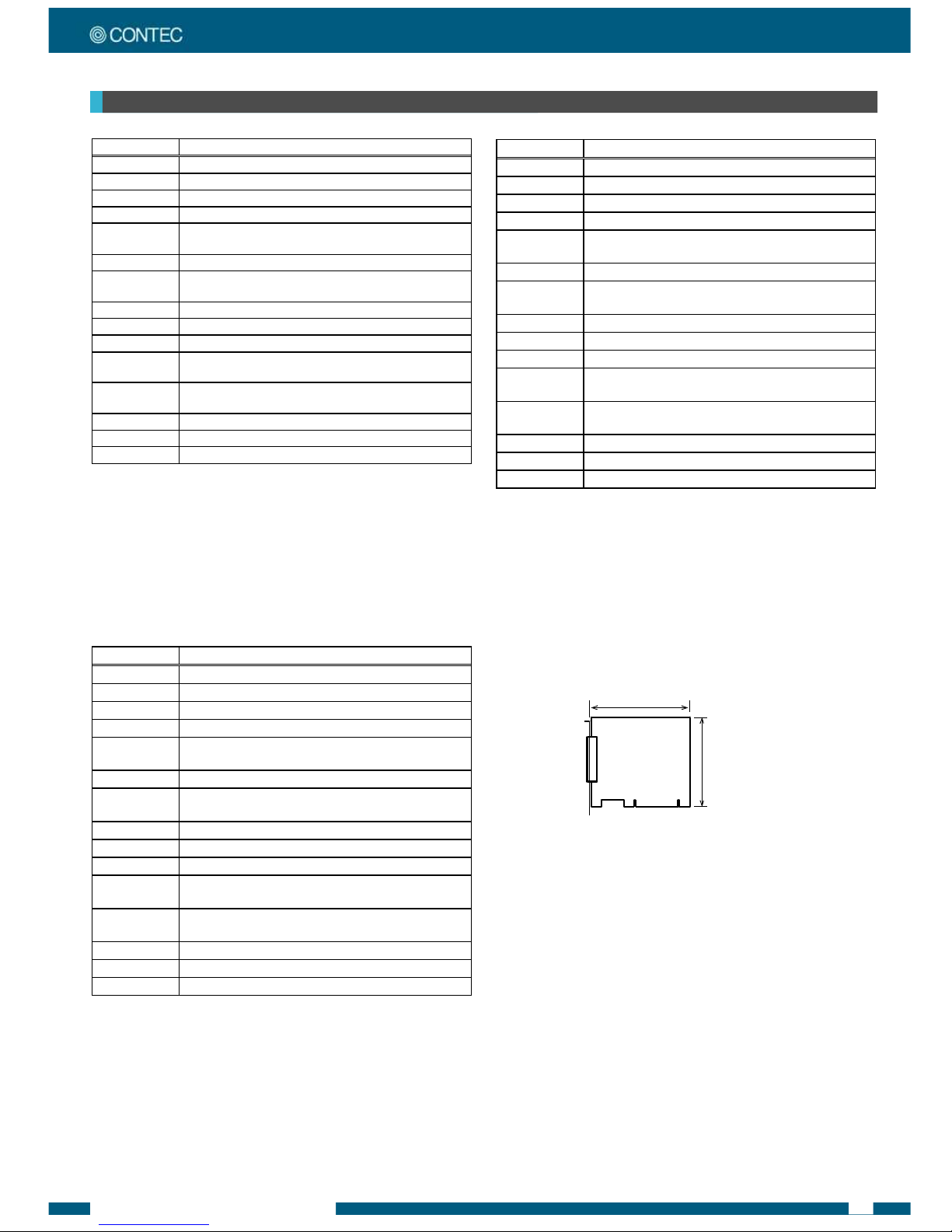
BoardDimensions
[COM-2(PCI)H,COM-4(PCI)H,COM-8(PCI)H]
The standard outside dimension (L) is the distance
from the end of the board to the outer surface of the
slot cover.
The Board No. is described above the board.
121.69(L)
105.68(H)
[mm]
Page 3
3COM-2(PCI)H,4(PCI)H,8(PCI)H
www.co ntec.co m
Ver.3.30
Support Software
You should use CONTEC support software according to your
purpose and development environment.
Standard COM Driver Software COM Setup Disk COM Setup Disk
(Bundled)
The purpose of this software is to allow the CONTEC serial
communication boards to be used under Windows or Linux in the
same way as the standard COM ports on the PC. By installing
additional boards, you can use COM ports in the range COM1 COM256.
The boards can be used for all types of serial communications such
as for remote access service (RAS) and uninterruptible power supply
(UPS) applications.
Under Windows, the serial ports can be accessed using the standard
Win32 API communication routines (CreateFile( ), WriteFile( ),
ReadFile( ), and SetCommState( ), etc.) The serial ports are also
compatible with the Visual Basic communication control
(MSComm).
Under Linux, the serial ports are compatible with the operating
system's standard tty driver. The standard routines including open(
), close( ), read( ), write( ) are supported.
< Operating environment >
OS Windows XP, 2000, NT, Me, 98, etc..
▼ CAUTION
The maximum number of COM ports able to be used depends on
the configuration of your OS.
Driver library API-PAC(W32) (Available for downloading (free of
charge) from the CONTEC web site.)
API-PAC(W32) is the library software that provides the commands
for CONTEC hardware products in the form of Windows standard
Win32 API functions (DLL). It makes it easy to create high-speed
application software taking advantage of the CONTEC hardware
using various programming languages that support Win32 API
functions, such as Visual Basic and Visual C/C++.
It can also be used by the installed diagnosis program to check
hardware operations.
CONTEC provides download services to supply the updated drivers
and differential files.
For details, visit the CONTEC's Web site.
< Operating environment >
OS Windows XP, 2000, NT, Me, 98, etc..
Adaptation language Visual C/C++, Visual Basic, Delphi,
Builder, etc..
Others Each piece of library software
requires 50 megabytes of free hard disk space.
▼ CAUTION
This library provides local routines that are specific to CONTEC
(SioOpen( ), SioWrite( ), SioRead( ), SioStatus( ), etc.). These are
not compatible with the standard Win32 API communication
routines (CreateFile( ) and WriteFile( ), etc.).
External Connection
This chapter describes the interface connectors on the board.
Check the information available here when connecting an external
device.
In addition to connecting directly to the connector on the board, you
can also connect external devices via a connection conversion cable or
connection conversion unit.
- Connecting directly to the port connector.
- Using a connection conversion cable
(COM-4(PCI)H, COM-8(PCI)H)
- Using a connection conversion unit
(COM-4(PCI)H, COM-8(PCI)H)
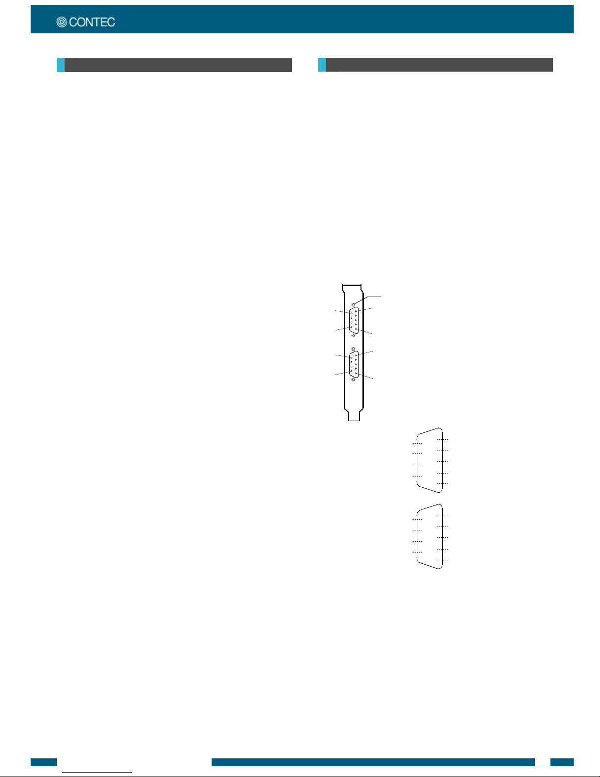
InthecaseofCOM-2(PCI)H
◆Connectingdirectlytotheportconnector
If connecting an external device directly from the connector on the
board, use a cable purchased separately. If making your own cable,
use a CN5-D9F or equivalent connector.
■ PinAssignment
CN1
CN2
1
6
5
9
6
9
1
5
- Connector used
DELC-J9PAF-20L9 (mfd. by JAE, Male)equivalent
- Applicable connector
17JE-13090-02(D8C) (mfd. by DDK, Male)
CN5-D9F (mfd. by CONTEC, Male) (Five connector set)
Screw nut: UNC#4-40(inch screw)
CN1
1
2
3
4
5
6
7
8
9
DCD1 Data Carrier Detect
RxD1 Receive Data
TxD1 Transmit Data
DTR1 Data Terminal Ready
SG1 Signal Ground
Data Set Ready DSR1
Request to Send RTS1
Clear to Send CTS1
Ring Indicator RI1
CN2
1
2
3
4
5
6
7
8
9
DCD2 Data Carrier Detect
RxD2 Receive Data
TxD2 Transmit Data
DTR2 Data Terminal Ready
SG2 Signal Ground
Data Set Ready DSR2
Request to Send RTS2
Clear to Send CTS2
Ring Indicator RI2
Cable (Option)
RS-232C Straight Cable with D-SUB9P (1.8m) RSS-9M/F
RS-232C Cross Cable with D-SUB9P (1.8m) RSC-9F
Page 4

4COM-2(PCI)H,4(PCI)H,8(PCI)H
www.co ntec.co m
Ver.3.30
InthecaseofCOM-4(PCI)H
When using a COM-4(PCI)H, an alternative to connecting an external device directly to the connector on the board is to use a connection
conversion cable or connection conversion unit.
◆ConvertingtheInterfaceConnectorto9-pinD-SUB,MaleConnectors
Use a PCE37/9PS connection conversion cable (purchased separately) to connect to external devices after dividing into four 9-pin D-SUB male
connector channels.
Use separately purchased 9-pin D-SUB or equivalent cables to connect from the four individual connectors.
- Connector used
37-pin D-SUB, male connector
Thumb screw :
UNC #4-40 (inch screw)
- Cable
9-conductor shielded cable
Cable length : 250mm
Conductor size : AWG#28
- Connector used
9-pin D-SUB, male connector
Thumb screw : UNC#4-40(inch screw)
- Applicable connectors
17JE-13090-02(D8C) (mfd. by DDK, Female)
.
.
.
SG 1
DTR 1
TxD 1
RxD 1
DCD 1
9
8
7
6
RI 1
CTS 1
RTS 1
DSR 1
5
4
3
2
1
CH1
SG 4
DTR 4
TxD 4
RxD 4
DCD 4
9
8
7
6
RI 4
CTS 4
RTS 4
DSR 4
5
4
3
2
1
CH4
CH1
CH2
CH3
CH4
■Connectionconversioncable(Option)
Connection Conversion Cable (37M 9M x 4, 250mm) PCE37/9PS
■ Cable(Option)
RS-232C Straight Cable with D-SUB9P (1.8m) RSS-9M/F
RS-232C Cross Cable with D-SUB9P (1.8m) RSC-9F
◆ConvertingtheInterfaceConnectorto25-pinD-SUB,MaleConnectors
Use a PCE37/25PS connection conversion cable (purchased separately) to connect to external devices after dividing into four 25-pin D-SUB male
connector channels.
Use separately purchased 25-pin D-SUB or equivalent cables to connect from the four individual connectors.
- Connector used
25-pin D-SUB, male connector
Thumb screw : UNC#4-40(inch screw)
- Applicable connectors
17JE-13250-02(D8C)
(mfd. by DDK, Female)
- Cable
9-conductor shielded cable
Cable length : 250mm
Conductor size : AWG#28
- Connector used
37-pin D-SUB, male connector
Thumb screw :
UNC #4-40 (inch screw)
CH1
CH2
CH3
CH4
.
.
.
N.C.
N.C.
N.C.
N.C.
N.C.
DCD 4
SG 4
DSR 4
CTS 4
RTS 4
RxD 4
TxD 4
N.C.
25
24
23
22
21
20
19
18
17
16
15
14
N.C.
N.C.
N.C.
RI 4
N.C.
DTR 4
N.C.
N.C.
N.C.
N.C.
N.C.
N.C.
13
12
11
10
9
8
7
6
5
4
3
2
1
CH4
25
24
23
22
21
20
19
18
17
16
15
14
N.C.
N.C.
N.C.
N.C.
N.C.
DCD 1
SG1
DSR 1
CTS 1
RTS 1
RxD 1
TxD 1
N.C.
N.C.
N.C.
N.C.
RI 1
N.C.
DTR 1
N.C.
N.C.
N.C.
N.C.
N.C.
N.C.
13
12
11
10
9
8
7
6
5
4
3
2
1
CH1
■Connectionconversioncable(Option)
Connection Conversion Cable (37M 25M x 4, 250mm) PCE37/25PS
Connection Conversion Cable for RS-232C (37M 25M x 4, 450mm) COM-4M CABLE(PC)1
■ Cable(Option)
RS-232C Straight Cable with D-SUB25P (1.8m) RSS-25M/F
RS-232C Cross Cable with D-SUB25P (1.8m) RSC-25F
RS-232C Connection Conversion Straight Cable (25M 9F, 1.8m) RSS-25M/9F
RS-232C Connection Conversion Straight Cable (25F 9M, 1.8m) RSS-25F/9M
RS-232C Connection Conversion Cross Cable (25F 9F, 1.8m) RSC-25F/9F
Page 5

5COM-2(PCI)H,4(PCI)H,8(PCI)H
www.co ntec.co m
Ver.3.30
◆WhenusingtheCCU-78F/25Mconnectionconversionunit
Use a CCU-78F/25M connection conversion unit (purchased separately) to connect to external devices after dividing into four 25-pin D-SUB male
connector channels.
This method has the following features.
- The unit can be fitted to a DIN rail using a separately purchased ADP-1 DIN rail adapter.
- The unit can be fitted to a wall or similar using screws.
- By connecting an external power supply, the unit can output a power supply from the 25-pin D-SUB connector.
Use a separately purchased 25-pin D-SUB connector cable to connect from the four individual connectors.
RS-232C cables connecting
to external devices
To Board
CCU-78F/25M
Connection conversion unit
for the COM-8ch/4ch board
Option
cable
25-pin D-SUB
connector
Ex ternal
equipment
Ex ternal
equipment
Ex ternal
equipment
.
.
.
1
2
3
4
5
6
7
8
9
10
11
12
13
14
15
16
17
18
19
20
21
22
23
24
25
- Connector used
25-pin D-SUB, male connector
Thumb screw: UNC#4-40(inch screrw)
- Applicable
17JE-13250-02(D8C)(mfd. by DDK, Female)
CN5-D25F (mfd. by CONTEC, Female) (Five connector set)
* A power supply output is referred to.
N.C.
N.C.
N.C.
N.C.
N.C.
N.C.
Data Terminal Ready DTR
N.C.
Ring Indicator RI
N.C.
N.C.
Power supply output *
FG
TxD Transmit Data
RxD Receive Data
RTS Request to Send
CTS Clear to Send
DSR Data Set Ready
SG Signal Ground
DCD Data Carrier Detect
N.C.
N.C.
N.C.
N.C.
N.C.
■ Connectionconversioncable&connectionconversionunit(Option)
Connection Conversion Unit for RS-232C(78P 25P x 8) CCU-78F/25M
COM-4ch Board Optional Cable for CCU-78F/25M (2m) RSS-78M/37M
■Connectioncable(Option)
RS-232C Straight Cable with D-SUB25P (1.8m) RSS-25M/F
RS-232C Cross Cable with D-SUB25P (1.8m) RSC-25F
RS-232C Connection Conversion Straight Cable (25M 9F, 1.8m) RSS-25M/9F
RS-232C Connection Conversion Straight Cable (25F 9M, 1.8m) RSS-25F/9M
RS-232C Connection Conversion Cross Cable (25F 9F, 1.8m) RSC-25F/9F
◆Connectingdirectlytotheportconnector
If connecting an external device directly from the connector on the
board, use a CN5-D9F or equivalent connector.
■ PinAssignment
37
20
19
1
- Connector used
37-pin D-SUB, male connector
DCLC-J37SAF-20L9 (mfd. by JAE)equivalent
- Applicable connector
17JE-23370-02(D8C) (mfd. by DDK, Male)
FDCD-37P (mfd. by HIROSE, Male)
DC-37P-N (mfd. by JAE, Male)
CN5-D37M (mfd. by CONTEC, Male) (Five connector set)
Screw nut: UNC#4-40(inch screw)
19
18
17
16
15
14
13
12
11
10
9
8
7
6
5
4
3
2
1
TxD1 CH1 Transmit Data 1
RTS1 CH1 Request to Send 1
DSR1 CH1 Data Set Ready 1
DTR1 CH1 Data Terminal Ready 1
RI1 CH1 Ring Indicator 1
RxD2 CH2 Receive Data 2
CTS2 CH2 Clear to Send 2
SG2 CH2 Signal Ground 2
DCD2 CH2 Data Carrier Detect 2
TxD4 CH4 Transmit Data 4
RTS4 CH4 Request to Send 4
DSR4 CH4 Data Set Ready 4
DTR4 CH4 Data Terminal Ready 4
RI4 CH4 Ring Indicator 4
RxD3 CH3 Receive Data 3
CTS3 CH3 Clear to Send 3
SG3 CH3 Signal Ground 3
DCD3 CH3 Data Carrier Detect 3
N.C.
37
36
35
34
33
32
31
30
29
28
27
26
25
24
23
22
21
20
CH1 Receive Data 1 RxD1
CH1 Clear to Send 1 CTS1
CH1 Signal Ground 1 SG1
CH1 Data Carrier Detect 1 DCD1
CH2 Transmit Data 2 TxD2
CH2 Request to Send 2 RTS2
CH2 Data Set Ready 2 DSR2
CH2 Data Terminal Ready 2 DTR2
CH2 Ring Indicator 2 RI2
CH4 Receive Data 4 RxD4
CH4 Clear to Send 4 CTS4
CH4 Signal Ground 4 SG4
CH4 Data Carrier Detect 4 DCD4
CH3 Transmit Data 3 TxD3
CH3 Request to Send 3 RTS3
CH3 Data Set Ready 3 DSR3
CH3 Data Terminal Ready 3 DTR3
CH3 Ring Indicator 3 RI3
CN1
Page 6

6COM-2(PCI)H,4(PCI)H,8(PCI)H
www.co ntec.co m
Ver.3.30
InthecaseofCOM-8(PCI)H
When using a COM-8(PCI)H, an alternative to connecting an external device directly to the connector on the board is to use a connection
conversion cable or connection conversion unit.
◆ConvertingtheInterfaceConnectorto9-pinD-SUB,MaleConnectors
Use a PCE78/9PS connection conversion cable (purchased separately) to connect to external devices after dividing into eight 9-pin D-SUB male
connector channels.
Use separately purchased 9-pin D-SUB or equivalent cables to connect from the eight individual connectors.
CH1
CH2
CH3
CH4
CH5
CH6
CH7
CH8
5
4
3
2
1
SG 1
DTR 1
TxD 1
RxD 1
DCD 1
9
8
7
6
RI 1
CTS 1
RTS 1
DSR 1
- Cable
9-conductor shielded cable
Cable length : 1m
Conductor size : AWG#28
- Connector used
9-pin D-SUB, male connector
Thumb screw : UNC#4-40(inch screw)
- Applicable connectors
17JE-13090-02(D8C)
(mfd. by DDK, Female)
- Connector used
78-pin D-SUB, male connector
Thumb screw :
UNC #4-40 (inch screw
.
.
.
.
.
.
.
.
.
CH1
CH8
5
4
3
2
1
SG 8
DTR 8
TxD 8
RxD 8
DCD 8
9
8
7
6
RI 8
CTS 8
RTS 8
DSR 8
■Connectionconversioncable(Option)
Connection Conversion Cable (78P 25P x 8) PCE78/9PS
■Connectioncable(Option)
RS-232C Straight Cable with D-SUB9P (1.8m) RSS-9M/F
RS-232C Cross Cable with D-SUB9P (1.8m) RSC-9F
◆ConvertingtheInterfaceConnectorto25-pinD-SUB,MaleConnectors
Use a PCE78/25PS connection conversion cable (purchased separately) to connect to external devices after dividing into eight 25-pin D-SUB male
connector channels.
Use separately purchased 25-pin D-SUB or equivalent cables to connect from the eight individual connectors.
■Connectionconversioncable(Option)
Connection Conversion Cable (78P 25P x 8) PCE78/25PS
■Connectioncable(Option)
RS-232C Straight Cable with D-SUB25P (1.8m) RSS-25M/F
RS-232C Cross Cable with D-SUB25P (1.8m) RSC-25F
RS-232C Connection Conversion Straight Cable (25M 9F, 1.8m)
RSS-25M/9F
RS-232C Connection Conversion Straight Cable (25F 9M, 1.8m)
RSS-25F/9M
RS-232C Connection Conversion Cross Cable (25F 9F, 1.8m)
RSC-25F/9F
CH1
CH2
CH3
CH4
CH5
CH6
CH7
CH8
N.C.
N.C.
N.C.
N.C.
N.C.
DCD 8
SG 8
DSR 8
CTS 8
RTS 8
RxD 8
TxD 8
N.C.
25
24
23
22
21
20
19
18
17
16
15
14
N.C.
N.C.
N.C.
RI 8
N.C.
DTR 8
N.C.
N.C.
N.C.
N.C.
N.C.
N.C.
13
12
11
10
9
8
7
6
5
4
3
2
1
CH8
N.C.
N.C.
N.C.
N.C.
N.C.
DCD 1
SG1
DSR 1
CTS 1
RTS 1
RxD 1
TxD 1
N.C.
25
24
23
22
21
20
19
18
17
16
15
14
N.C.
N.C.
N.C.
RI 1
N.C.
DTR 1
N.C.
N.C.
N.C.
N.C.
N.C.
N.C.
13
12
11
10
9
8
7
6
5
4
3
2
1
CH1
- Cable
9-conductor shielded cable
Cable length : 1m
Conductor size : AWG#28
.
.
.
.
.
.
.
.
.
- Connector used
78-pin D-SUB, male connector
Thumb screw :
UNC #4-40 (inch screw)
- Connector used
9-pin D-SUB, male connector
Thumb screw : UNC#4-40(inch screw)
- Applicable connectors
17JE-13090-02(D8C)
(mfd. by DDK, Female)
Page 7

7COM-2(PCI)H,4(PCI)H,8(PCI)H
www.co ntec.co m
Ver.3.30
When using the CCU-78F/25M connection conversion unit
Use a CCU-78F/25M connection conversion unit (purchased separately) to connect to external devices after dividing into eight 25-pin D-SUB
male connector channels.
This method has the following features.
- The unit can be fitted to a DIN rail using a separately purchased ADP-1 DIN rail adapter.
- The unit can be fitted to a wall or similar using screws.
- By connecting an external power supply, the unit can output a power supply from the 25-pin D-SUB connector.
Use a separately purchased 25-pin D-SUB connector cable to connect from the eight individual connectors.
◆Connectingdirectlytotheportconnector
If connecting an external device directly from the connector on the board, use a CN5-D78M or equivalent connector.
RS-232C cables connecting
to external devices
To Board
CCU-78F/25M
Connection conversion unit
for the COM-8ch/4ch board
Option
cable
25-pin D-SUB
connector
Ex ternal
equipment
Ex ternal
equipment
Ex ternal
equipment
.
.
.
1
2
3
4
5
6
7
8
9
10
11
12
13
14
15
16
17
18
19
20
21
22
23
24
25
- Connector used
25-pin D-SUB, male connector
Thumb screw: UNC#4-40(inch screrw)
- Applicable
17JE-13250-02(D8C)(mfd. by DDK, Female)
CN5-D25F (mfd. by CONTEC, Female) (Five connector set)
* A power supply output is referred to.
N.C.
N.C.
N.C.
N.C.
N.C.
N.C.
Data Terminal Ready DTR
N.C.
Ring Indicator RI
N.C.
N.C.
Power supply output *
FG
TxD Transmit Data
RxD Receive Data
RTS Request to Send
CTS Clear to Send
DSR Data Set Ready
SG Signal Ground
DCD Data Carrier Detect
N.C.
N.C.
N.C.
N.C.
N.C.
■Connectionconversioncable
&connectionconversionunit(Option)
Connection Conversion Unit for RS-232C(78P 25P x 8) CCU-78F/25M
COM-8ch Board Optional Cable for CCU-78F/25M (2m) RSS-78M
■Connectioncable(Option)
RS-232C Straight Cable with D-SUB25P (1.8m) RSS-25M/F
RS-232C Cross Cable with D-SUB25P (1.8m) RSC-25F
RS-232C Connection Conversion Straight Cable (25M 9F, 1.8m) RSS-25M/9F
RS-232C Connection Conversion Straight Cable (25F 9M, 1.8m) RSS-25F/9M
RS-232C Connection Conversion Cross Cable (25F 9F, 1.8m) RSC-25F/9F
Pin No. Signal
name
Pin No. Signal
name
Pin No. Signal
name
Pin No. Signal
name
78 N.C. 59 DSR 1
39 RTS 1 20 TxD 1
77 SG 1 58 DCD 1
38 CTS 1 19 RxD 1
76 N.C. 57 RI 1
37 DSR 2 18 DTR 1
75 SG 2 56 DCD 2
36 RTS 2 17 TxD 2
74 RI 2 55 DTR 2
35 CTS 2 16 RxD 2
73 N.C. 54 DSR 3
34 RTS 3 15 TxD 3
72 SG 3 53 DCD 3
33 CTS 3 14 RxD 3
71 DSR 4 52 RI 3
32 RTS 4 13 DTR 3
70 SG 4 51 DCD 4
31 CTS 4 12 TxD 4
69 RI 4 50 DTR 4
30 DSR 5 11 RxD 4
68 SG 5 49 DCD 5
29 RTS 5 10 TxD 5
67 RI 5 48 DTR 5
28 CTS 5 9 RxD 5
66 N.C. 47 DSR 6
27 RTS 6 8 TxD 6
65 SG 6 46 DCD 6
26 CTS 6 7 RxD 6
64 N.C. 45 RI 6
25 DSR 7 6 DTR 6
63 SG 7 44 DCD7
24 RTS 7 5 TxD 7
62 RI 7 43 DTR 7
23 CTS 7 4 RxD 7
61 N.C. 42 DSR 8
22 RTS 8 3 TxD 8
60 SG 8 41 DCD 8
21 CTS 8 2 RxD 8
40 RI 8
CN1
1214060
20
395978
1 DTR 8
■ PinAssignment
- Connector used
78-pin D-SUB, female connector
DV11603G4 (mfd. by FOXCONN)equivalent
- Applicable connector
CN5-D78M (mfd. by CONTEC, Male) (Five connector set)
59
39
78
20
60 1
40 21
Screw nut: UNC#4-40(inch screw)
The connector used for COM8-(PCI)H has a wide interpin space and is highly reliable.
In the case of a PC with a narrow slot opening, a gap might be created as wide as the
thickness of the sheet metal of the PC when an external cable is connected, preventing
the connector from being fitted properly. If the thickness of the sheet metal is less than
1.5mm (typically about 1.0mm), simply tighten the adjusting screw located on the side
of the connector to install it properly. The connector should function without a problem.
Thickness of the sheet metal
(about 1.0mm)
PC case
Bracket
Circuit
boards
Thickness of
the bracket (0.8mm)
The slot
opening width
Cable side
connectors
Page 8

8COM-2(PCI)H,4(PCI)H,8(PCI)H
www.co ntec.co m
Ver.3.30
Types of Cable and Example Connections
The connector used for COM8-(PCI)H has a wide interpin space and is highly reliable. In the case of a PC with a narrow slot opening, a gap
might be created as wide as the thickness of the sheet metal of the PC when an external cable is connected, preventing the connector from being
fitted properly. If the thickness of the sheet metal is less than 1.5mm (typically about 1.0mm), simply tighten the adjusting screw located on the
side of the connector to install it properly. The connector should function without a problem.
Differences to the COM-2(PCI), COM-4(PCI), and COM-8(PC)
The COM-2(PCI)H, COM-4(PCI)H, and COM-8(PCI)H boards are an enhancement of the previous COM-2(PCI), COM-4(PCI), and COM8(PCI) board models and are upwardly compatible with the COM-xx(PCI) boards. Accordingly, the boards can generally be used in the same way
as the COM-xx(PCI) boards.
There are some differences in the specifications.
Please refer to the EXAR Corporation data sheet for details about the LSI used on the boards.
COM-2(PCI)H
COM-2(PCI) COM-2(PCI)H
Baud rate 230.4kbps 921.6kbps
FIFO buffer for
transmission and
reception
16-byte 128-byte
Controller chip 16552 or equivalent 162850 or equivalent
COM-4(PCI)H
COM-4(PCI) COM-4(PCI)H
Baud rate 230.4kbps 921.6kbps
FIFO buffer for
transmission and
reception
16-byte 128-byte
Boards in one system
Maximum of 8 boards can be
install in a same system.
Maximum of 16 boards can
be install in a same system.
Controller chip 16552 or equivalent 162850 or equivalent
COM-8(PCI)H
COM-8(PCI) COM-8(PCI)H
Baud rate 230.4kbps 921.6kbps
FIFO buffer for
transmission and
reception
64-byte 128-byte
Controller chip 16554 or equivalent 162850 or equivalent
ExampleConnectiontoaModem(Straightcable)
TxD
RxD
RTS
CTS
DTR
DSR
SG
TxD
RxD
RTS
CTS
DTR
DSR
SG
(Transmit Data)
(Receive Data)
(Request to Send)
(Clear to Send)
(Data Terminal Ready)
(Data Set Ready)
(Signal Ground)
External device
ExampleConnectiontoaPC(Crosscable)
TxD
RxD
RTS
CTS
DTR
DSR
SG
TxD
RxD
RTS
CTS
DTR
DSR
SG
External device
ExampleConnectiontoaDevice
TxD
RxD
RTS
CTS
DTR
DSR
SG
TxD
RxD
RTS
CTS
DTR
DSR
SG
External device
Page 9

9COM-2(PCI)H,4(PCI)H,8(PCI)H
www.co ntec.co m
Ver.3.30
Differences between the COM-2(PCI)H, COM-4(PCI)H and COM-8(PCI)H
The COM-2(PCI)H, COM-4(PCI)H, and COM-8(PCI)H are different in specifications, depending on the board number as listed below.
COM-2(PCI)H
Board No. No.7189 No.7189A No.7189B
PCI bus
specification
32bit, 33MHz, 5V 32bit, 33MHz,
Universal key shapes supported
(5 V is supplied to the 5V pin.)
32bit, 33MHz,
Universal key shapes supported
(Power voltage is set by jumper.)
Power voltage
setting jumper
(JP1)
Absent Absent Present
Power
consumption
5VDC 250mA(Max.)
5VDC 250mA(Max.) 3.3VDC 100mA (Max.)
5VDC 100mA (Max.)
External
dimension
121.69(L) x 106.68(H)
121.69(L) x 105.68(H) 121.69(L) x 105.68(H)
COM-4(PCI)H
Board No. No.7190 No.7190A No.7190B
PCI bus
specification
32bit, 33MHz, 5V 32bit, 33MHz,
Universal key shapes supported
(5 V is supplied to the 5V pin.)
32bit, 33MHz,
Universal key shapes supported
(Power voltage is set by jumper.)
Power voltage
setting jumper
(JP1)
Absent Absent Present
Power
consumption
5VDC 500mA(Max.)
5VDC 500mA(Max.) 3.3VDC 150mA (Max.)
5VDC 150mA (Max.)
External
dimension
121.69(L) x 106.68(H)
121.69(L) x 105.68(H) 121.69(L) x 105.68(H)
COM-8(PCI)H
Board No. No.7191A No.7191B No.7191C
PCI bus
specification
32bit, 33MHz, 5V 32bit, 33MHz,
Universal key shapes supported
(5 V is supplied to the 5V pin.)
32bit, 33MHz,
Universal key shapes supported
(Power voltage is set by jumper.)
Power voltage
setting jumper
(JP1)
Absent Absent Present
Power
consumption
5VDC 600mA(Max.)
5VDC 600mA(Max.) 3.3VDC 250mA (Max.)
5VDC 250mA (Max.)
External
dimension
121.69(L) x 106.68(H)
121.69(L) x 105.68(H) 121.69(L) x 105.68(H)
 Loading...