

Page 1
CMS800G
FETAL MONITOR
CONTEC MEDICAL SYSTEMS CO., LTD
Page 2

TABLE OF CONTENTS
1 Safety Guidance ………………………………………………………………………………….2
1.1 Introduction For The Safe Operation ……………………………………………………2
1.2 Ultrasound Safety Guide ……………………………………………………………………2
1.3 Safety Precautions ………………………………………………………………………...3
2 Introduction………………………………………………………………………………………5
2.1 Intended Use and Application………………………………………………………………5
2.2 Features………………………………………………………………………………………5
3 Monitor and Setup………………………………………………………………………………..6
3.1 The Monitor…………………………………………………………………………………..6
3.2 Setup………………………………………………………………………………………….11
4 Installation………………………………………………………………………………………..16
4.1 Open the Package and Check………………………………………………………………16
4.2 Connect the Power Cable…………………………………………………………………...16
4.3 Connect with Network………………………………………………………………………17
4.4 Feeding Paper and Removing Paper Jam…………………………………………………17
4.5 Power On the Monitor………………………………………………………………………17
4.6 Connect Transducers………………………………………………………………………..17
5 Monitoring………………………………………………………………………………………..17
5.1 Operation Procedure ……………………………………………………………………….17
5.2 Print Operation……………………………………………………………………………...20
5.3 Operation After Monitoring ………………………………………………………………..21
6 Maintenance, Care and Cleaning……………………………………………………………….21
6.1 Preventive Maintenance…………………………………………………………………….21
6.2 Care and Cleaning of Monitor……………………………………………………………...22
6.3 Care and Cleaning of Transducer…………………………………………………………..22
6.4 Care of Recorder and Paper………………………………………………………………...23
6.5 Cleaning of Belt………………………………………………………………………………23
6.6 Sterilization…………………………………………………………………………………...24
6.7 Disinfection…………………………………………………………………………………...24
7 Warranties…………………………………………………………………………………...........24
Attachment 1 Product Specification……………………………………………………………….25
A 1.1 Monitor……………………………………………………………………………………..25
A 1.2 Transducers………………………………………………………………………………...26
Attachment 2 Troubleshooting……………………………………………………………………..27
Attachment 3 Monitoring Figure…………………………………………………………………..28
Page 3

Copyright
Copyright: Contec Medical System CO., LTD.2007
Attention
This document contains proprietary information protected by copyright law. No part of this
document may be photocopied, reproduced or translated to another language without prior written
consent of CONTEC.
CONTEC assumes no responsibility for any errors that may appear in this document, or for
incidental or consequential damage in connection with the furnishing, performance or use of this
material. The information contained in this document is subject to change without notice.
Responsibility of the Manufacturer
CONTEC only considers itself responsible for any effects on safety, reliability and performance of
the equipment if:
Assembly operations, extensions, re-adjustments, modifications or repairs are carried out by
persons authorized by CONTEC, and the electrical installation of the relevant room complies with
national standards, and the instrument is used in accordance with the instructions for use.
Note: This device is not intended for home use.
WARNING : This device is not intended for treatment.
If there is doubt as to fetal well-being after using the unit, further investigations should be
undertaken immediately using alternative techniques.
The accuracy of FHR is controlled by the equipment and can not be adjusted by user.
If the FHR result is distrustful, please use other method such as stethoscope to verify
or contact the local distributor or manufacture to get help.
Using This Label Guide
This guide is designed to give key concepts on safety precautions.
WARNING
A WARNING label advises against certain actions or situations that could result in personal injury
or death.
CAUTION
A CAUTION label advises against actions or situations that could damage equipment, produce
inaccurate data, or invalidate a procedure.
Note: A NOTE provides useful information regarding a function or procedure.
Page 4

1 Safety Guidance
1.1 Introduction For the Safe Operation
The CMS800G Ultrasonic Fetal Doppler Monitor (Monitor) is Class I equipment and
designed to comply with IEC 60601-1.
Switching within 1 minute, at ambient temperatures between 5℃ and 40℃ . Ambient
temperatures that exceed these limits could affect the accuracy of the instrument and cause
damage to the modules and circuits. Allow at least 2 inches (5cm) clearance around the
instrument for proper air circulation.
The user must check the equipment, cables and transducers do not have visible evidence of
damage that may affect patient safety or monitoring capability before use. The recommended
inspection interval is once per week or less. If damage is evidence, replacement is
recommended before use.
The user must be serviced only by authorized and qualified personnel, The manufacturer can
not accept responsibility for safety compliance, reliability and performance if modifications
or repairs are carried out by unauthorized personnel. Identical replacement parts must be
used.
Perform period safety testing to insure proper patient safety. This should include leakage
current measurement and insulation testing. The recommended testing interval is once per
year.
The protection categories against electric shock of the patient connections are:
①FHR1 ②FHR2 ③TOCO MARK④
This symbol indicates that the instrument is IEC 60601-1 Type B equipment. Type B protection
means that these patient connections will comply with permitted leakage currents, dielectric
strengths and protective earthing limits of IEC 60601-1.
The monitor described in this user manual is not protected against:
A) The effect of defibrillator shocks
B) The effects of defibrillator discharge
C) The interference of high frequency currents
D) The interference of electrosurgery equipment
E) The interference of mobile phone
1.2 Ultrasound Safety Guide
Fetal Use
The Monitor is designed for continuous fetal heart rate monitoring during pregnancy and
labor . Clinical interpretation of fetal heart rate patterns can diagnose fetal and/or maternal
problems and complications.
Instructions for Use in Minimizing Patient Exposure
The acoustic output of the Monitor is internally controlled and can not be varied by the
operator in the course of the examination. The duration of exposure is, however, fully under
the control of the operator. Mastery of the examination techniques described in the User
Manual will facilitate obtaining the maximum amount of diagnostic information with the
minimum amount of exposure.
Page 5

1.3 Safety Precautions
WARNING and CAUTION messages must be observed. To avoid the possibility of injury,
observe the following precautions during the operation of the instrument.
WARNING : EXPLOSION HAZARD-Do not use the in a flammable atmosphere where
concentrations of flammable anesthetics or other materials may occur.
WARNING : SHOCK HAZARD-the power receptacle must be a three-wire grounded
outlet. A hospital grade outlet is required. Never adapt the three-prong
plug from the monitor to fit a two-slot outlet. If the outlet has only two
slots, make sure that it is replaced with a three-slot grounded outlet before
attempting to operate the monitor.
WARNING : SHOCK HAZARD-Do not attempt to connect or disconnect a power cord
with wet hands. Make certain that your hands are clean and dry before
touching a power cord.
WARNING : The monitor should be installed by an authorized and qualified service
engineer.
WARNING : SHOCK HAZARD-Do not remove the top panel covers during operation or
while power is connected.
WARNING : Only connect the device to Contec supplied or recommended accessories, to
avoid the injury of the doctors and patient.
WARNING : Do not switch on device power until all cables have been properly connected
and verified.
WARNING : Don’t touch signal input or output connector and the patient simultaneously.
WARNING : Accessory equipment connected to the analog and digital interfaces must be
certified according to the respective IEC standards (e.g. IEC 950 for data
processing equipment and IEC 60601-1 for medical equipment). Furthermore
all configurations shall comply with the valid version of the system standard
Page 6

IEC 60601-1-1. Everybody who connects additional equipment to the signal
input connector or signal output connector configures a medical system, and is
therefore responsible that the system complies with the requirements of the
valid version of the system standard IEC 60601-1-1. If in doubt, consult our
technical service department or your local distributor.
CAUTION : The device is designed for continuous and is “ordinary” (i.e. not drip or
splash-proof).
CAUTION : Keep the environment clean. Avoid vibration. Keep it far from corrosive
medicine, dust area, high-temperature and humid environment.
CAUTION : Do not operate the unit if it is damp or wet because of condensation or spills.
Avoid using the equipment immediately after moving it from a cold
environment to a warm, humid location.
CAUTION : Do not immerse transducers in liquid. When using solutions, use sterile wipes
to avoid pouring fluids directly on the transducers.
CAUTION
CAUTION
CAUTION : The temperature should not exceed 6
CAUTION : Electromagnetic Interference-Ensure that the environment in which the
CAUTION : The monitor must serviced by proper training and knowledge, practical
Do not use high temperature heating or gas to disinfect the monitor and its
④
accessories.
Turn off the power supply before clean the machine.
④
when clean the belt.
0℃
fetal monitor is installed is not subject to any sources of strong
electromagnetic interference, such as radio transmitters, mobile telephones,
etc.
personnel. The recommended testing interval is once twice year or under the
leakage current measurement and insulation testing.
Page 7

CAUTION : The device and reusable accessories could be sent back to the manufacturer
for recycling or proper disposal after their useful lives.
2 Introduction
The Fetal Monitor can provide different configurations according to different user requirements:
FHR1 (Ultrasonic Channel ), FHR2 (Ultrasonic Channel ),TOCO, FMOV (Fetal MovementⅠ Ⅱ
Marker). Monitoring results can be recorded by built-in recorder for continuous or intermittent
records.
The monitor can be used individually or connected with PC through RJ45 Interface for the
purpose of central monitoring.
2.1 Intended Use and Application
Fetal Monitor can acquire fetal heart rate, maternal uterine contraction when pregnancies over 28
weeks to provide reference data for clinical use.
Dual Heart Rate Monitoring allows simultaneous monitoring of two heart rates for twins. This is
achieved by using the facilities of two ultrasound transducers and an external contractions
(TOCO) transducer with a recorder.
The monitor can display FHR, TOCO, MARK (remote) sinuously, by analyzing their mutual
relations, to judge fetal physiology, pathology and maternity status, and so on, for medical
professionals reference.
It is only suitable for the equipment in hospitals, clinics, doctors offices and patients at home by
trained medical personnel.
2.2 Features
Light dexterous appearance, tops horizontally and walls can be hoisted
8.4screen color LCD display, rotatable screen to 60°
Display of the patient data and curve clearly
Print paper fetal heart rate 120-160bpm normal range label
Manual records fetal movement
Sound and color alarm for high and low fetal heart rate
Continuous 24-hour real-time monitoring function
Continuous 12-hour patient curve and data storage and playback
With picture freeze function
Optional English interface
Page 8

Single, Twins Monitoring optional
9 chip pulse width beam probe
Extra-long life, high-resolution built-in thermal printer matrix, the output waveform, text, and
other information
Built-in communication port, can be connected with central monitoring system.
3 Monitor and Setup
3.1 The Monitor
Figure 3.1 Appearance (Twins configuration, only for reference)
3.1.1 Transducer Introduction
Ultrasound TransducerⅠ④TOCO Transducer④Remote Marker④Ultrasound TransducerⅡ
Ultrasound TransducerⅠ
④1④
The multi-crystal, broad beam ultrasound transducer is used for monitoring fetal heart
rate(FHR1).The ultrasound transducer operates at a frequency of 1.0MHz. Put the ultrasound
transducer on maternal abdomen to transmit lower energy ultrasound wave to fetal heart, then
receive the echo signal from it.
TOCO Transducer
④2④
This transducer is a toco tonometer whose central section is depressed by the forward
displacement of the abdominal muscles during a contraction. It is used for assessment of
frequency and duration of uterine contractions. It gives a subjective indication of contractions
pressure.
Remote Marker
④3④
The remote marker is a hand-held switch operated by patient. The mother is normally instructed
Page 9
to push down the switch when feeling fetal movement.
Ultrasound TransducerⅠ④TOCO Transducer④Remote Marker are three in one transducers, their
sockets are marked FHR1/TOCO/MARK on the monitor panel.
Ultrasound TransducerⅡ is the transducer for FHR 2(Twins Configuration), it’s socket is
④4④
marked FHR2 on the monitor panel.
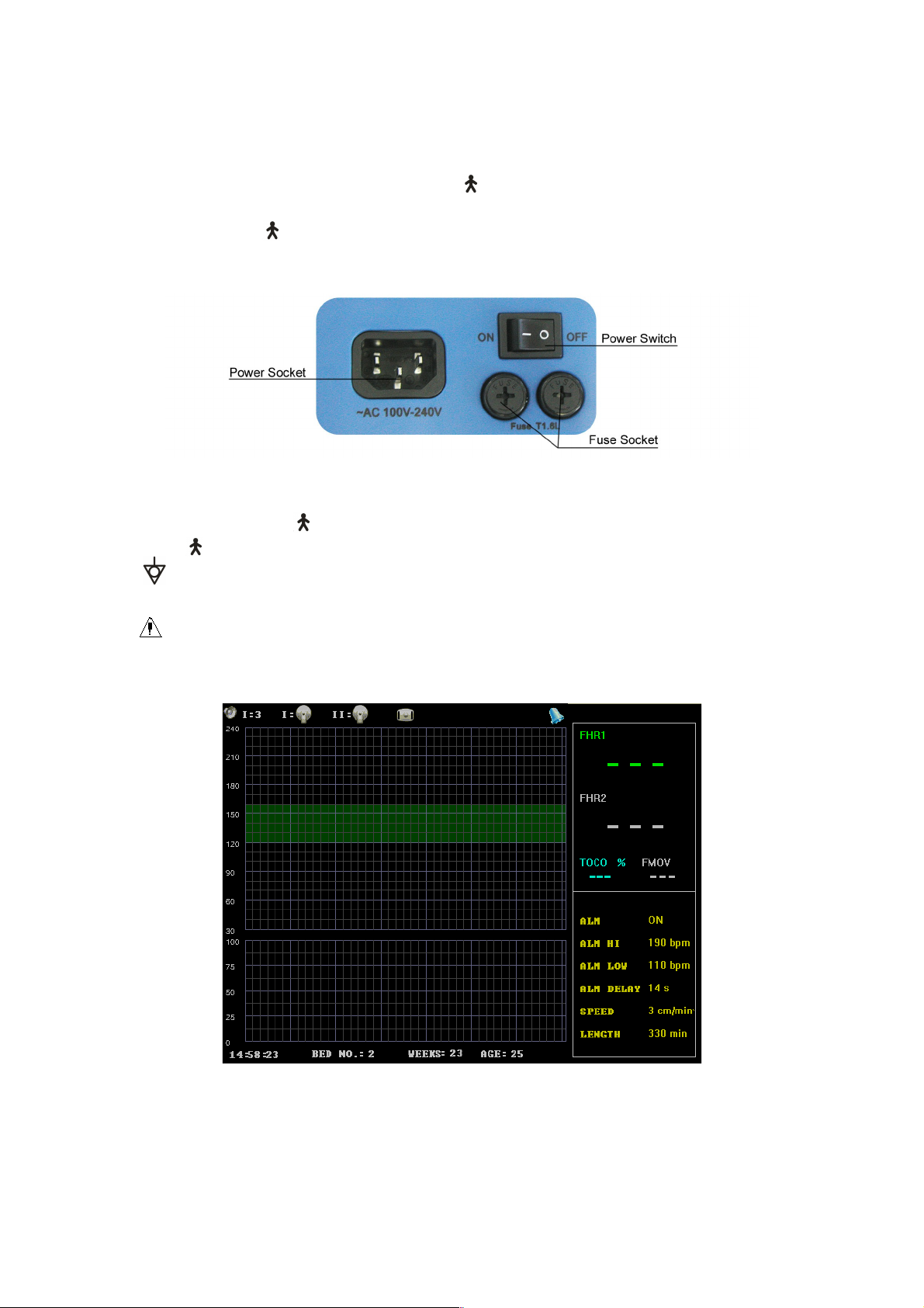
3.1.2 Left Side Sockets
Figure 3.2 Left Side Sockets
3.1.3 Interfaces and Symbols
FHR1/TOCO/MARK socket: Socket for FHR1/TOCO transducer and remote Marker
FHR2 socket: Socket for FHR2 Transducer
: Socket for Grounding Cable
NET.: Socket for network
: Warning Symbol
Push: LCD Screen rotation lock
3.1.4 Main Interface
Figure 3.3 Twins Monitoring interface
The main monitoring interface(Twins Monitoring) is divided into 5 parts according to display
content, they are status bar ④data section④parameter section④indicate bar and wave display section.
It displays in status bar that sound channel and volume④connection status of ultrasound Transducer
I④ultrasound Transducer II(twins monitoring) and TOCO transducer, Freeze status④print
Page 10
status④alarm on /off; It displays FHR 1 from Ultrasound Transducer I④FHR 2 from Ultrasound
Transducer II (Twins monitoring) and TOCO④Fetal Movement data; parameter section displays the
important parameter of current settings; time④bed number④time of pregnancy and age of pregnant
woman are displayed in indicate bar; waves from ultrasound transducer I channel④ultrasound
transducer II channel(Twins Monitoring) and TOCO transducer are displayed in wave display
section. Detail instruction as followed.
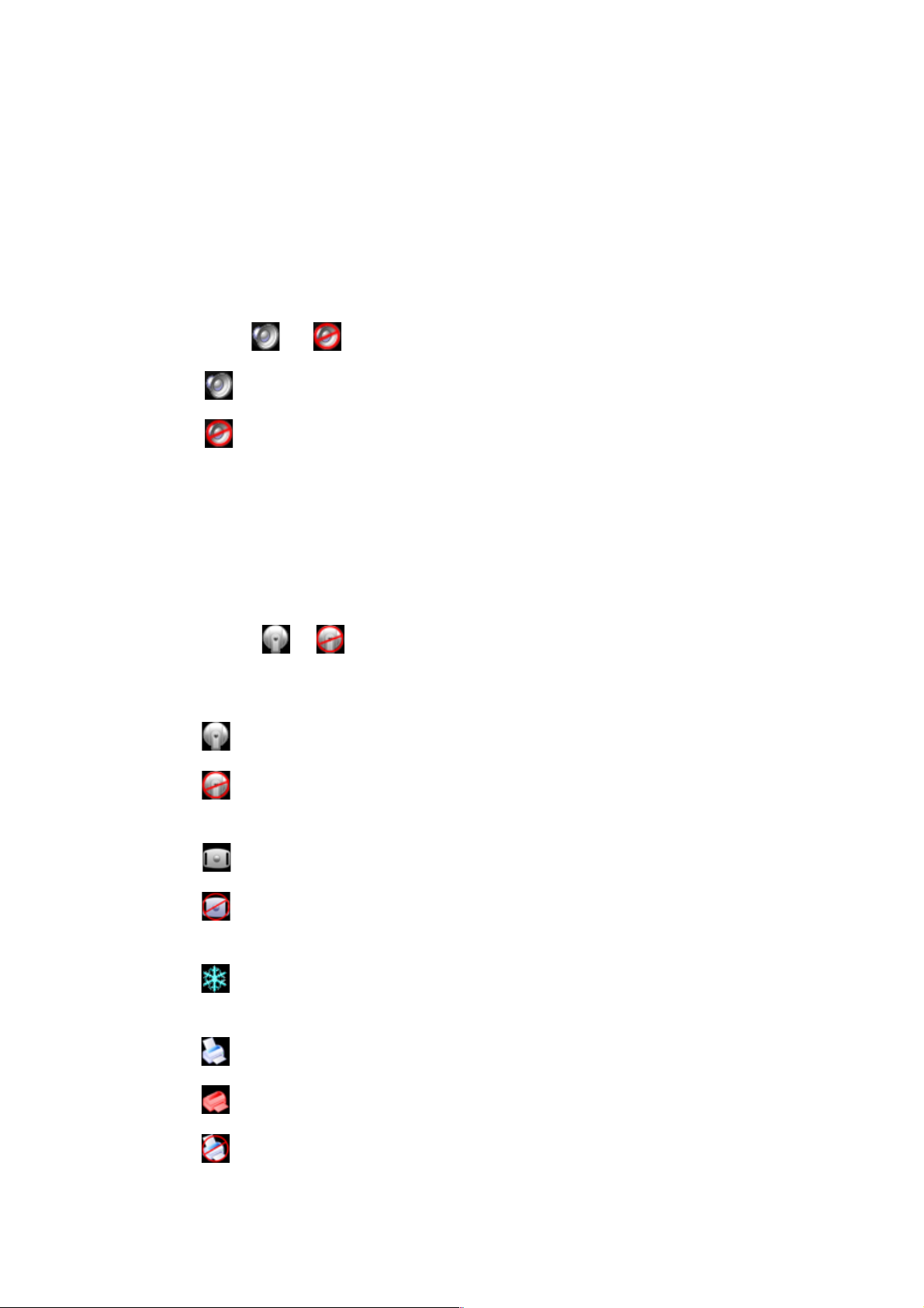
Status Bar
(1(
Sound channel and volume
④A④
Icon
④Sound Icon
④Sound off Icon
I④The No. of FHR sound channel, it is I under single fetal monitoring mode which is
default; I④II selectable under twins monitoring mode, it can be changed through
the main menu.
3④Volume level, ranging from 0-7, 0 stands for sound off. It can be changed through the
buttons on the panel or set in the main menu.
Connection status of ultrasound transducer
④B④
IconⅠ④: : Ⅱ
I④Channel No. of ultrasound transducer, there is only I under single monitoring mode,
there are I and II under twins monitoring mode
④Normal connection of ultrasound transducer
④Error connection of ultrasound transducer
④ Ⅰ
:3 Ⅰ:0
Connection Status of TOCO transducer
④C④
④Normal connection of TOCO transducer
④Error connection of TOCO transducer
Freeze status
④D④
④Shows current screen is frozen; icon will disappear when unfrozen.
Recorder status
④E④
④Printing
④out of paper
④Failed to print
Page 11

Alarm on/off status
④F④
④Alarm on
④Alarm off
Data Section
(2(
FHR 1 Data of Ultrasound Transducer I④3-digit data, it is in green color under normal
status, it will be in red when alarm occurs; it displays “―――” when there is no data.
FHR 2 Data of Ultrasound Transducer II: this data will show in twins monitoring mode, the
display format is the same with the FHR 1.
TOCO data④Display the relative contraction data, ranging from 0-100, it will be 10 after
Auto Zero.
Fetal Movement Data ④Display Fetal movement numbers, it will be “―――” after Auto
Zero.
Parameter Bar
(3(
This section displays important setting parameters: it contains alarm on/off status④alarm
upper limit④lower limit④alarm postpone time④print speed and print time.
Indicate Bar
(4(
In this item, it includes system time④bed No.④gestational age and patient age.
Wavefom Display Section
(5(
This section also be divided into 2 sections, FHR trend graph is displayed in the upper
section, TOCO waveform is displayed in lower section. FHR1 Trend is in green④FHR2 trend
is in Yellow(only displayed in twins monitoring)④the normal range of the fetal heart rate is
120-160bpm④which be showed in green on the screen.
Fetal movement mark “↑”④alarm mark ④event mark “↓” will also be showed in this section.
3.1.5 Buttons
There are several buttons of different functions on the front panel of fetal monitor. The diagram is
showed as Figure 3.4.
Page 12

Figure 3.4 Buttons
Menu Button
(1(
Push Menu Button to enter setup menu, push it again to return monitor screen. When operating in
other menu, push this button to return this menu. Only turning knob button can exit wave review
mode.
Detailed operation please refer Figure 3.2
(2(
Function: Enable/Stop audio alarm when FHR is in alarm range.
When symbol appears, the alarm indicator status is shut off.
Press the button to enable audio alarm, the alarm indicator becomes , when FHR is in alarm
situation, the alarm sound will be given out.
(3(
Function: Clear the screen, TOCO value back to 10 unit,
Press this button to clear the screen and adjust the present TOCO contractions trace/value to
reference point 10 when in the status of monitoring, after pressing the AUTO ZERO button, the
symbol “ ” will be recorded at the trace.
Alarm Button
Auto Zero Button
Page 13

(4(
Function: Enable/Disable printing.
Press PRINT button in normal situation, if it not works, it begins real-time printing
Press PRINT button in frozen situation, it prints the waveform on the screen.
Print Button
(5(
: Volume down :Volume up
Function: adjust the audio volume of the Fetal heart Sound.
④6④
Function: Press this button to print an event symbol on the screen trend figure at the corresponding
time. If user want to mark an event on the trend figure, he/she could achieve this by pushing this
button.
④7④
Function: Freezing the screen. Press the button to stop drawing and the screen becomes in frozen
status, press the button again to continue drawing. This operation will clear the screen.
④8④
Volume Control Button
Event Button
Freeze Button
Knob Key
1 Press the button to activate the selected button, press it again to accept the configuration.
2 To choose and adjust the parameters by revolving the knob key.
Paper Cabinet Open Button
(9 (
Push this button for opening the paper cabinet.
(10(“
Function: Push this button to unlock the screen for rotation purpose.
Note: Please lock the LCD Screen during transportation to avoid any damage of the monitor.
3.2 Setup
Under Main monitoring interface, Press the Menu button or knob key to enter setup mode, the
diagram is showed as Figure 3.5
Push” – LCD Screen Rotation Lock
Page 14

Figure 3.5 Setup
Revolving knob key to select different function. The Corresponding function and the adjustable
ranges are showed in table3.1.
Table 3.1 The setup function and adjustable ranges
No Function Adjustable Ranges
1 ALM SET(Alarm Setup) Enter Alarm Setup
2 PAT SET(Patient Setup) Enter Patient Setup
3 SYSTEM SET(System Setup) Enter System Setup
4 REVIEW(Waveform Review) Enter Waveform Review
5 PRINT SET(Print Setup) Enter Print Setup
6 MONI TYPE(Monitor Mode) Optional: single, twins the default is
single fetus
7 LANGUAGE(Language Selection) Optional: Chinese (CH), English (EN),
the default is EN.
8 CHANNEL I(Audio Channel I
Setup)
9 CHANNEL II(Audio Channel II
Setup)
10 CHANNEL(Audio Channel) Optional: I, II, fetal heart audio come
11 EXIT Exit main menu, back to main interface
Adjustable:1④7 and mute,
the default is 3
Adjustable:1④7 and mute,
the default is 3
from the selected channel.
Alarm Setup
(1(
Revolving the knob key to enter alarm setup, the diagram is showed as Figure 3.6:
Page 15

Figure 3.6 Alarm Setup
Revolving the knob key to setup alarm function. The Corresponding function and the adjustable
ranges are showed in the table3.2:
Table 3.2 The alarm setup function and adjustable ranges
No Function Adjustable Range
1 FHR ALM(FHR Alarm) Optional: Turn on, shut off The default situation
is alarm on.
Note:
1
2
Patient Setup
(2(
2 ALM HIGH(FHR Upper Limit of
Alarm)
3 ALM LOW(FHR Lower Limit of
Alarm)
4 ALM DELAY(FHR Alarm Delay)
When FHR is in alarm situation, alarm indicator becomes red
When FHR exceeds the alarm limit and time exceed the set alarm delay time
continuously, alarm will occur and an alarm symbol will appear on the screen.
Optional: lower limit of alarm-310, the unit is
BPM, and the default is 190
Optional: high limit of alarm 0 ④FHR, the unit is
BPM, and the default is 110
Optional:0④60,the unit is second, and the default
is 30 seconds
Revolving the knob key to enter patient setup, the diagram is showed as Figure 3.7:
Figure 3.7 Patient Setup
Revolving the knob key to setup patient function. The Corresponding function and the adjustable
ranges are showed in the table3.3:
Table 3.3 the patient setup function and adjustable ranges
No Function Adjustable Ranges
1 NAME(Name) Optional: 12 letter or numeral. The default is blank
2 AGE(Age) Optional: numeral from 1-100. The default is 25
3 BED NO.(Bed No.) Optional: numeral from 1-100. The default is 1
4 PAT NO.(Case History No.) Optional: 12 letter or numeral. The default is blank
Page 16

5 ROOM(Ward No.) Optional: 5 letter or numeral. The default is blank
6 LENGTH(Time of Pregnancy) Optional: 1-100.The unit is week. The default is 0
7 BLOOD(Blood Type) Optional: A, B, AB, O, and N(unknown). The default is N.
8 PARTUS NUM(Times of Giving Birth Optional: 0-20, the default is 0
9 FETAL NUM.(Quantity of Fetus) Optional: 0-20, the default is 1
10 PREGNANT NUM(Times of
Pregnancy)
11 WEIGHT(Patient’s Weight)
12 HEIGHT(Patient’s Height)
13 DELETE(Delete Information) Delete related patient information
14 SAVE(Save Information) Save related patient information, return to previous menu
15 Exit Return to previous menu
Note: ① When adjustable range is letter or number, numeral and letter key will turn on
automatically after entering the setup, in which:
SP: Space bar
CAPS: Capital letters lock
OK: Setup finished, exit keyboard output mode
DEL: Delete, delete one selected letter or number after each push.
The main interface prompt box will show the patient’s data renewal after save the
②
patient’s data.
Optional: 0-20, the default is 1
2-250, interval④0.5Kg,unit: Kg or Pound; the default value
is 65Kg
20-300, interval ④ 0.5cm(inch) ④ unit: cm or inch; the
default value is 165cm
System Setup
(3(
Revolving the knob key to enter system setup, the diagram is showed as Figure 3.8:
Figure 3.8 System Setup
Time Setup
①
Revolving the knob key to enter time setup, the diagram is showed as Figure 3.9:
Figure 3.9 Time Setup
Revolving the knob key to enter time setup function. The Corresponding function and the
Page 17

adjustable ranges are showed in the table3.4:
Table 3.4 The time setup function
No Function Adjustable Ranges
1 YEAR
2 MONTH
3 DAY
4 HOUR
5 MINUTE
6 SECOND
7 SAVE SET(Save) Save setup and return to previous menu
8 EXIT(Exit) Exit to previous menu
NOTE: The main interface prompt box will show the time renewal after save the time setting.
NET NO.(
Be used for connecting with
System Update(
This device supports system update service. In system setup menu, revolving the knob key to enter
System update.
Note: Please enter password under the item “USR KEY” before click “CONFIRM”. This
password is provided by manufacturer or distributor when Contec add new function to upgrade the
system.
④Version
Revolving the knob key to enter System setup, choose version item and push the knob key to see
the equipment version
Wave review
(4(
Choose the WAVE REVIEW in the setup menu to enter wave review, and press WAVE REVIEW
in this item to review the history wave, which is showed as Figure 3.10
central monitoring system.
Optional:2005④2036
Optional:1④12
Optional:1④31
Optional:0④23
Optional:0④59
Optional:0④59
→
Figure 3.10 Review
Select lright (left or right), or revolve the knob key to view monitoring wave in different time, the
end time for the current monitoring wave is showed at the down right corner in the show area. The
wave form could be reviewed for twelve hours as the longest.
Print Setup
(5(
Revolving the knob key to enter print setup, the diagram is showed as Figure 3.11:
Page 18

Figure 3.11Print Setup
Revolving the knob key to setup print function. The Corresponding function and the adjustable
ranges are showed in the table3.5:
Table 3.5 The print setup function and adjustable ranges
No Function Adjustable Range
1 SPEED(Print
Speed)
2 LENGTH(Print
Length)
73 BASELINE(Baselin
e offset)
4 BASELINE PRINT Print the ladder-from testing wave.
5 PAPER(Selection of
printing paper type)
6 EXIT Return to the upper menu.
4 Installation
Note: To ensure that the monitor works properly, please read this chapter and Chapter 1 Safety
Guidance. And follow the steps before using the monitor.
4.1 Open the Package and Check
Open the package and take out the monitor and accessories carefully. Put the monitor at safe and
reliable place. Check the components according to the packing list.
Check for any mechanical damage.
Check all the cable, and accessories.
If there is any problem, contact us for your local distributor immediately.
1cm/min, 2cm/min, and 3cm/min. The default value is 3cm/min.
0④24(hours) ,the interval is 10 minutes.
The default value is 30 minutes.
Adjustable:-10~+10, the interval is 1, the default value is0.
Please select it between American standard printing paper and
Europe standard printing paper.
4.2 Connect the Power Cable
Make sure the AC power supply of the monitor complies with the following specification:
100V-240AV, 50/60Hz.
Consider the local power supply range, if the power supply of the monitor exceeds the range,
please add regulator equipment.
Apply the power socket of the monitor. Plug one end of the power cable to the power socket
of the monitor. Connect the other end of the power cable to a grounded 3-phase power output
special for hospital usage.
Connect the ground wire if necessary.
Page 19

Connect with Network
4.3
If the network has been ready, insert the network cable into the RJ45 interface of the monitor.
4.4 Feeding Paper and Removing Paper Jam
If the paper is used up or paper jam happens, you have to feed paper into the recorder, the
operation procedure is as follows:
Open the paper cabinet
1
Take out the “Z” type thermal sensitive paper from the wrapper. Put the green safety band to
2
the left and the face of the paper downward. Please refer to “paper installation note” on the
bottom of the cabinet.
Feed the record paper into the slot of the recorder and push out form the middle of the notch.
3
Close the paper cabinet properly.
4
Removing Paper Jam
When the recorder sounds or the output of the paper improper, open the paper cabinet to check for
a paper jam, then feed the paper again.
Note: Only use the manufacturer approved paper to avoid poor printing quality, deflection,
or paper jam.
4.5 Power on the Monitor
WARNING: If any sign of damage is detected, do not use it on any patient. Contact
biomedical engineer in the hospital or our service engineer immediately.
Turn on the power, and the power indicator lights, the monitoring screen lights.
NOTE: There will be initialization time for some seconds after turn on the monitor to the
monitoring screen shows data, and the system will enter normal monitoring after self-test.
4.6 Connect Transducers
Connect all the necessary transducers, and cables between the monitor and the patient.
Note: please pay attention to the direction when connecting transducer(s), the
arrow mark in the
connector should head upward.
5. Monitoring
5.1 Operation Procedure
Ultrasound Transducer and TOCO Transducer Positioning showed as Figure 5.1
Page 20

Figure 5.1 Ultrasound Transducer & TOCO Transducer Positioning
5.1.1 Ultrasound Monitoring of FHR
Ultrasound monitoring can be used for antepartum monitoring; it is a method to obtain FHR
through maternal abdominal wall. Put the FHR transducer on maternal abdomen to transmit lower
energy ultrasound wave to fetal heart, then receive the echo signal from it.
Operation Procedure:
Preparing the Monitor
1
Turn the monitor on and verify that the normal monitoring screen appears on the display.
Check the ultrasound transducer to verify proper attachment to the monitor. For twins monitoring,
make sure the second ultrasound transducer if properly connected.
Set the current heart rate channel to channel US1, and adjust FHR1 volume well.
Attach the buckle of the ultrasound transducer to the belt. Apply aquasonic coupling gel to the
face of the transducer.
2 Acquiring the Fetal Heart Signal
Determine the location of the fetal heart using palpation or a fetoscope.
Place the ultrasound transducer on the abdomen over fetal site and move it slowly until the
characteristic hoof-beat sound of the fetal heart is heard. And then fix up the ultrasound transducer.
The elasticity of belt can be adjusted, which make the patient monitored in the comfortable
situation, and the fetal heart rate value will be shown on the screen. At the same time, the
ultrasound wave will be drawn in green color on the screen.
3 Acquiring Twins’ Heart Rates Signal
CMS800G is able to monitoring twins’ heart rates through two ultrasound transducers during the
whole pregnant time.
Follow the step②mentioned above to acquire the heart rate for the first fetus.
Set the current heart rate channel to US2, and adjust FHR2 volume well so that the second heart
sounds can be heard
Page 21

Determine the location of the second fetal signal using palpation or a fetoscope.
Attach the buckle of the ultrasound transducer to the belt. Apply aquasonic coupling gel to the face
of the transducer. Place the second ultrasound transducer on the abdomen over fetal site and move
it slowly until the characteristic hoof-beat sound of the fetal heart is heard.
The fetal heart rate value FHR2 will be shown on the screen. At the same time, the ultrasound
wave will be drawn in yellow color on the screen.
CAUTION: Do not mistake the higher maternal heart rate for fetal heart rate.
4 Monitor Adjustments:
Adjust the position of ultrasound scanner according to the need.
There is only one fetal heart sound can be heard from the speaker, change it by selecting different
channel of fetal heart sound (the first sound channel for FHR1, and the second sound channel for
FHR2)
Readjust the volume setting for the desired loudness.
Note:
The ultrasound transducer measures the FHR; the misuse of it will be result in wrong
measurement or misunderstanding of it. So it requires the doctor pay attention to it:
The best quality records will only be obtained if the transducer is placed in the optimum
①
position.
Positions with strong placental sounds (swishing) or fetal cord pulse (indistinct pulse at
②
fetal rate) should be avoided.
If the fetus is in the cephalic position and the mother is supine, the clearest heart sound
③
will normally be found on the midline below the umbilicus. During monitoring prolonged
lying in the supine position should be avoided owing to the possibility of supine hypotension.
Sitting up or lateral positions are preferable and may be more comfortable to the mother.
It is not possible to FHR unless an audible fetal heart signal is present. The fetal pulse can
④
be distinguished from the maternal pulse by feeling the mother’s pulse during the
examination.
During the monitoring, the doctor should observe the monitor screen, if the screen break
⑤
off frequently, the position of the ultrasound transducer may had out of proper position due
to the moving of the fetus.
During the monitoring, if the FHR can be heard without steadily sound of the fetal heart,
⑥
it may not proper positions. So move it slowly until the proper position is found. But if it is
not found, the doctor should do other examination, to observe if the fetus is normal.
5.1.2 Monitoring Contractions
Operation Procedure:
1 Preparing the Monitor
Turn the monitor on and verify that the normal monitoring screen appears on the display.
Insert the TOCO Transducer into the socket.
Page 22

Acquiring Uterine Contraction Data
2
Fix the transducer. The transducer is retained on the midline half-way between the mother’s
fundus and the umbilicus. The position is shown as figure5.1
The display of external pressure is shown as a percentage % of full scale. The uterine activity
reading at this point should be greater than 30 units and less than 90 units. If the reading falls
outside this range, the belt may be too tight or too loose.
Zero can be set more quickly by pressing the AUTO ZERO button on the front panel, provided
③
the mother is not experiencing a contraction. The default contraction data will be 10% after press
the AUTO ZERO button.
Caution: Under no circumstances are transducers to be used to monitor patients under water.
Note: ① Do not use coupling gel on the TOCO transducer or transducer contact area.
Check the function by TOCO transducer, and observe the change of relevant value.
②
5.1.3 Event Marker Recording of Fetal Movement
The event marker is a hand-held switch the mother takes. When FHR is monitored, she operates
the hand-held event marker press-switch when sensing fetal movement. At the moment, the mark
“↑” will show in the correspond position of trend wave. The count of fetal movement will add 1
after each push of the button. Push the button and hold for one second then release for counting
one fetal movement, the fetal movement will be only counted once if the button is pushed more
than one time during 5 seconds. And the mark will show in the bottom area of FHR wave display
section.
5.2 Print Operation
Baseline Adjustment
(1(
When start the monitor, recorder will print the baseline automatically, please check if the base
line snap to grid of the paper. If the baseline wave has some warp with the paper grid, operator
can adjust the baseline by the baseline adjustment in main menu. Recorder will standby after
printing baseline.
Operator could choose baseline test function in the print setup menu to test baseline at any time.
Real Time Print
(2(
Push print button under monitoring and recorder standby status to print real time wave, the print
icon is ④push th e print button to stop the printing process when recorder is printing.
Recall Print
(3(
Use know key to select wave to print in wave review status, and then push print button to print
the selected wave.
Freeze Print
(4(
Push print button in freeze status to print the wave displayed in screen.
Print Content
(5(
Page 23

The print output content contains: BED NO.④NAME④WEEKS④PATIENT NO.④FHR1
trend④FHR2 trend④Twins Monitoring④④TOCO wave④print speed④date④time.
It also contains other icons like④auto zero mark ④alarm mark ④FMOV mark “↑”④event mark
“↓” etc.
Note
when
5.3 Operation After Monitoring
Remove transducers from patient. Wipe transducer with a soft cloth to remove remaining
①
Tear the paper at the folding place.
②
Switch off the power of monitor.
③
when paper is used out, printing will stop, and the data will be saved in memory,
(①
paper reloaded, operator can use wave review function to print the saved data.
the monitor has the function of 12-hour wave storage, review and print. Record
②
will not saved when monitor is turned off.
To ensure print precisely, recommend to print and adjust the baseline when paper
③
is loaded .
if the paper coming out from the notch in deflection way when printing, the data
④
may be not precise or paper jam will occur, operator should stop printing and
reload paper.
Please set all print parameters well before printing, and do not try to change the(
setup in the process of printing.
ultrasound coupling gel.
Maintenance, Care and Cleaning
6
To ensure that the monitor works properly, please read the manual and operation procedure as well
as the maintenance before using the monitor, and operate it as requested.
6.1 Preventive Maintenance
(1) Visual Inspection
The user must check that the equipment, cables and transducers do not have visible evidence of
damage that may affect patient safety or monitoring capability before use. The recommended
inspection interval is once per week or less. If damage is evident, replacement is recommended
before use.
(2) Routine Inspection
The equipment should undergo periodic safety testing to insure proper patient isolation from
leakage currents. This should include leakage current measurement and insulation testing. The
recommended testing interval is once a year or as specified in the institution’s test and inspection
protocol.
Page 24

(3) Mechanical Inspection
Make sure all exposed screws are tight.
Make sure all models and connector are in proper positions.
Check the external cables for splits; cracks or signs of twisting replace any cable that shows
serious damage.
WARNING: Failure on the part of the responsible individual hospital or institution
employing the use of this equipment to implement a satisfactory maintenance schedule may
cause undue equipment failure and possible health hazards.
6.2 Care and Cleaning of Monitor
Keep the exterior surface of the monitor clean and free of dirt.
Regular cleaning of the monitor casing and the screen is strongly recommended. Use only non-
caustic detergents such as soap and water to clean the monitor casing.
Take extra care when cleaning the display surface. These are more sensitive to rough handling,
scratches and breakage than the other external surface of the monitor. Use dry, and soft cloth to
wipe.
WARNING: Unplug the monitor from the AC power source and detach all accessories before
cleaning. Do not immerse the unit in water or allow liquids to enter the casing.
CAUTION:
Many cleaners must be diluted before use. Follow the manufacturer’s direction carefully to
1
avoid damaging the monitor.
Do not use strong solvent, for example, acetone.
2
Do not remain any cleaning solution on the surface of the monitor.
3
The monitor surface can be cleaned with hospital-grade ethanol and dried in air or with crisp
4
and clean cloth.
The manufacturer has no responsibility for the effectiveness of controlling infectious disease
5
using these chemical agents. Please contact infectious disease experts in your hospital for
details.
6.3 Care and Cleaning of Transducer
Maintenance
(1 (
Usually, the transducer should keep clean and maintain in dry environment, where the temperature
should be lower than 45 degrees. Gel must be wiped from the ultrasound transducer after use.
These precautions will prolong the life of the transducer.
Page 25

Although transducers are designed for durability, they should be handled with care. Rough
handling could damage the cover, piezoelectric crystals and mechanical movement. The cover is
made of a soft plastic, and contact with hard or sharp objects should be avoided. Do not
excessively flex the cables.
WARNING: Under no circumstance are transducers to be used to monitor patients under
water.
CAUTION: Be sure that the cleaning solution and transducers do not exceed a temperature
of 45 degrees.
Cleaning of Ultrasound Transducer, TOCO Transducer and Remote Marker.
(2(
Wipe the transducer with a cloth.
1
Clean the transducer with a cloth soaked in a solution of soap and water, or a cleaning
2
solution.
Do not immerse the transducer in the solution. Or a cloth soaked in a solution of 70%
ethanol to clean the transducer. When using a cleaning solution, follow the manufacturer’s
directions carefully to avoid damaging the transducer.
Wipe the transducer with a cloth soaked in water.
3
Wipe the remained humidity with clean and dried cloth.
4
6.4 Care of Recorder and Paper
Note: Please do not use paper not recommended by CONTEC or we will not warrant to
repair if any damage occurs.
When storing recorder paper (including used paper with traces):
Do not store in plastic envelopes.
Do not leave exposed to direct sunlight or ultraviolet light.
Do not exceed a storage temperature of 400C.
Do not exceed a humidity of 80%.
Storage conditions outside these limits may distort the paper and adversely affect the accuracy of
grid lines or make the trace unreadable.
6.5 Cleaning of Belt
Wash soiled belts with soap and water. The water temperature must not exceed 60 0C.
6.6 Sterilization
To avoid extended damage to the equipment, sterilization is only recommended when stipulated as
necessary in the hospital maintenance schedule. Sterilization facilities should be cleaned first.
Page 26

The sterilization the manufacturer recommended to cleaning the monitor and accessories are
ethanol and Acetaldehyde.
CAUTION: To avoid damaging the monitor:
Follow the manufacturer’s instruction to dilute the solution, or adopt the lowest possible
1
density.
Do not let liquid enter the monitor.
2
No part of this monitor can be subjected to immersion in liquid.
3
Do not pour liquid onto the monitor during sterilization.
4
Wipe the device with a clean moistened cloth to remove any remaining sterilant.
5
6.7 Disinfection
To avoid extended damage to the equipment, disinfect ion is only recommended when stipulated
as necessary in the hospital maintenance schedule. Disinfections facilities should be cleaned first.
CAUTION:
Follow the manufacturer’s instruction to dilute the solution.
①
Do not use bleaching powder containing chloros on any parts of the monitor.
②
Do not disinfect the monitor and it’s accessories with autoclave④gassing④formaldehyde process
③
or radiation.
Check carefully after cleaning, sterilization, or disinfect ion of monitor and accessories. If
④
aging and damage are found, please do not use them to monitor.
Note: The manufacturer has no responsibility for the effectiveness of controlling infectious
disease using these chemical agents. Please contact infectious disease experts in your
hospital for details.
7 Warranties
The manufacturer warrants that the Fetal Monitor we sell is free from defects in material and
workmanship. In the status of normal operation and maintenance, if the manufacturer receives
notice of such defects during the warranty period that begins on the date of shipment, the
manufacturer shall, at its options, either repair or replace hardware products that prove to be
defective. The unit is guaranteed for periods of 12 months, valid from the date of purchase. The
manufacturer also provides long-term repair service for our clients.
The manufacturer’s obligations or liability under this warranty does not include any transportation
or other charges or liability for direct, indirect or consequential damages or delay resulting from
the following conditions.
The following conditions are not included in the warranty:
1 Assembly operation, extensions, re-adjustments are carried out by the importer.
2 Application of the products or repaired by anyone other than the manufacturer authorized
representative.
3 This warranty shall not extend to any instrument that has been damaged subjected to misuse,
Page 27

negligence or accident.
4 This warranty shall not extend to any instrument from which the manufacturer’s original serial
number tag or product identification marking have been altered or removed.
5 The product were operated and used not properly.
Attachment 1 Product Specification
A1.1 Monitor
Physical Characteristics
Size: 320 (length) × 260 (width) × 80 (height) mm
Weight: about 3.2 Kg
Security: The Monitor obey the following norms and standards: IEC 60601-1-4④IEC 60601-1-2
Anti-shock types: Facilities I, no internal power supply
Anti-electric Shock Degree: B
Degree of protection against Harmful Ingress of Water: Moderate equipment and do not have the
ability to waterproof immersion
Degree of Safety in Presence of Flammable Gases: not suitable for use in presence of flammable
gases
Electromagnetic Compatibility: Group Ⅰ Class A
Mode: continuous work
Power Supply
Working Voltage: AC 100V ~ 240V
Frequency: 50Hz/60Hz
P④60VA
Fuse: T1.6AL
Environment
Transport and storage
Temperature: -10 °C ~55 °C
Relative Humidity: ≤ 93%
Atmospheric pressure: 70kPa ~ 106kPa
Working environment
Temperature: 5 °C~ 40 °C
Relative Humidity: ≤ 80%
Atmospheric pressure: 70kPa ~ 106kPa
Display
Dimensions: 8.4 "color LCD display, folding 60 degree
Display Content: bed No. , pregnancy age, age, single/twins type, paper speed, date,
time , volume, alarm status, transducer connection status, recorder status, FHR data
and wave, Contraction data and wave, Fetal move times and mark etc.
Print: Record Paper two-double type Z
Print Width: 112mm
Valid Print Width: 104mm
Paper output speed: 1cm/min④2cm/min④3cm/min(optional)
Data Precision: 5④④X Roll④④±1④④Y Roll
④
Page 28

Record Content: bed No. ,name, pregnancy age, single/twins type, case No., paper speed,
date, time , FHR data and wave, Contraction data and wave, Fetal move times and mark
etc.
Signal Interface: RJ 45
Ultrasound probe: Nominal Frequency: 1.0MHz
Work Frequency: 1.0MHz±10
④
Negative peak sound pressure : P_④1MPa
2④
Output beam intensity : Iob④20mW/cm
The peak time space peak intensity: Ispta④100mW/cm
The average time space peak intensity: Ispta④10mW/cm
④
2④
④
2④
④
FHR Rang: 65BPM④210BPM④Allow error: within ±2bpm
Resolution: 1BPM
Accuracy : ±2
④
TOCO
TOCO range: 0④100
Resolution: 1
Nonlinear error: ④±10
④
④
④
RZ way: Manually
Fetal Marking
For the manual button (the operation of pregnant women), there will be a mark display
in the bottom area of FHR wave display section.
FHR Alarm:
Alarm for high and low FHR, which exceeds appointed limit.
A 1.2 Transducers
(1) Ultrasonic Transducer
System: Pulsed Doppler
Dimension: 90mm × 65mm
(2) TOCO Transducer
System: Passive Straingauge
Dimension: 102mm × 50mm
(3) Remote Marker
Length: 3.2m
Attachment 2 Troubleshooting
Note: If trouble occurs during operation, examine the product by the following ways. If it
not works, please contact the local distributor or manufacturer; do not open the machine by
the user.
1 The screen not display
Shut off the power; pull out the power cord, to check the electrical current goes through the socket,
and the power cord connects with the equipment properly. To check the fuse, if it is melt down,
change the fuse.
Page 29

2 Noises
Symptom Possible Cause Solution
Noise Too high volume sets Adjust the volume down
Interfered by handset or other
interfering source
3 Recorder Errors
Symptom Possible Cause Solution
Paper jam Wrong feeding paper or paper is
affected with damp
Recorder does not work PRINT button is disabled Press the PRINT button again
Out of paper Feed paper
Just push print button, the printing of
last line not finished.
4 Ultrasound Monitoring of FHR
Keep the handset or other
interfering source far away
Feed paper correctly and keep
paper from moist
Waiting until it is finished.
Symptom Possible Cause Solution
Inconstant trace
Inconstant display
Doubtful FHR Record Fetal heart rate wrongly Change the position of
Feint trace or no trace Improper paper Use the paper recommended
Wrong FHR No
The pregnant woman is too fat No
Improper ultrasound transducer
position
Loose abdomen belt Tighten abdomen belt
Superfluous coupling gel Wipe off superfluous coupling
Fetal movement Wait for a moment then monitor
Maternal movement Relax patient’s spirit
Inadequate coupling gel Use recommended coupling gel
The ultrasound transducer is not
placed well on the abdomen, and
the mixed noise has been
recorded
Change the position of
ultrasound transducer
gel
quantity
ultrasound transducer
Change the position of
ultrasound transducer
by manufacturer
Page 30

5 Monitoring Contractions (External)
Symptom Possible Cause Solution
Worse trace quality or
fluctuant TOCO baseline
Too high TOCO sensitivity
(higher than 100 unit)
Attachment 3 Monitoring Figure
Too tight or too loose
abdomen belt or no
elasticity
Maternal Movement Relax patient’s spirit
Fetal Movement Wait for a moment then monitor
The body pressure from
uterus to TOCO
transducer is far higher
than the average value.
Ensure the abdomen belt has been
used accurately and neither too
tight, nor too loose
Insure favorable contact for patient
skin with TOCO transducer. Change
the position of TOCO transducer, if
necessary.
Page 31

CONTEC MEDICAL SYSTEMS CO., LTD
Address:#2-1 Hengshan Road, Qinhuangdao Economic &Technical Development Zone,
Hebei Province, PRC
Tel: +86-335-8015433
Fax: +86-335-8015432
E-mail: cms@contecmed.com.cn
Website: http://www.contecmed.com.cn
EC REPRESENTATIVE
Shanghai International Holding Corp. GmbH (Europe)
Address: Eiffestrasse 80, D-20537, Hamburg, Germany
Tel: &49-40-2513175
Fax: &49-40-255726
E-mail: shholding@hotmail.com
File No.: CMS2.782.029ESS/1.0
File Ver.: 1.0
Release Date: July .2007
 Loading...