

Page 1

IPC Series
BOX-PC
for BX-320 Series
User’s Manual
CONTEC CO., LTD.
Page 2

BX-320-DCxxxxxx*1
Model]
Name
Pcs.
Pcs.
The main body 1 1
DIN rail attachment fittings set
1*2
1*2
F&eIT module mettal fittings
2
2
Rubber foot 4 4
Washer assembled screw (M3 x 7)
6
6
Countersunk screw (M3 x5)
3
3
Connector cover
1*2
1*2
CFast card removal preventi on fitting
1
1
CFast card removal preventi on fitting
(bott om face side)
Cable clamp 1 1
Power connector 1 1
Product guide (this sheet)
1
1
IPC Precaution List
1
1
Warranty Certificate
1
1
Serial number label
1
1
Royalty consent contract (OS)
-*3
1
Setup Pr ocedure Document
-*3
1
Recovery Media
-*3
1
Check Your Package
Thank you f or purc hasing the CO N TEC pr o duct.
The product consists of the items listed below.
Check, with the following list, that your package is complete. If you discover damaged or missing items,
contact your retailer.
Product Config uration List
BX-320-DCx00000
[Base Model]
1*2 1*2
[OS Pre -installed
*1 Except for base model.
*2 It is at tached the main body.
*3 It is not packed to the Base model.
* The User’s Guide of this product is offered as the PDF file in our web page. With it, since information such as a
setup of hardware, each component function and BIOS setup is indicated, please refer to it if needed.
* User’s ma nual or driver library for using F&eIT Serie s device module is not attached to this product. Downl oading
them from the CONTEC Website is needed.
BX-320 User’s manu a l
i
Page 3
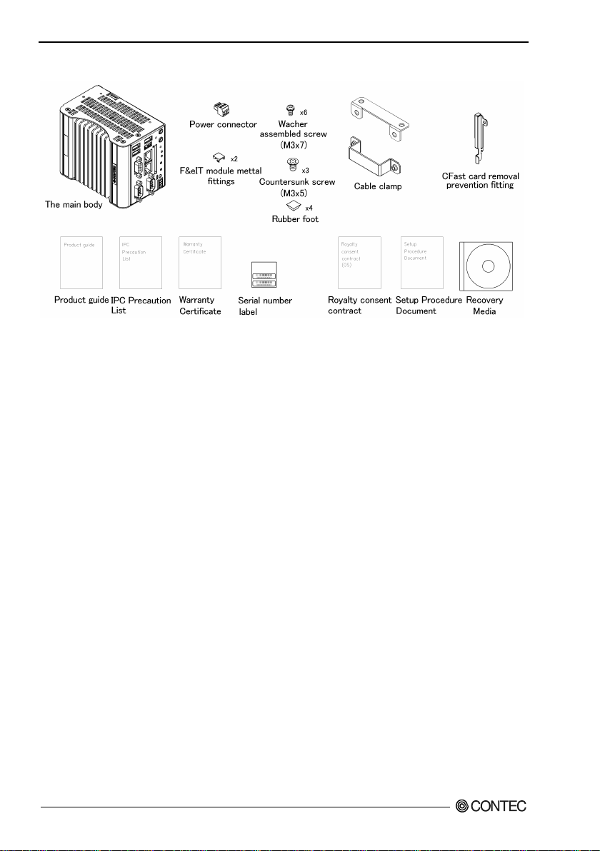
Product Config uration Image
* See the Product Configuration List to check if all the c omponents are incl uded for the specified n umber of units.
Copyright
Copyright 2016 CONTEC CO., LTD. ALL RIGHTS RESERVED.
No par t of thi s d o cument may be co pied or reproduc e d i n a ny for m by a ny mean s wi thout prior writt e n
consent of CONTEC CO., LTD.
CONTEC CO., LTD. makes no commitment to update or keep current the information contained in this
document.
The information in this document is subject to change without notice.
All relevant issues have been considered in the preparation of this document. Should you notice an
omission or any questionable item in this docume nt, please feel fre e to notify CONTEC CO., LTD.
Regardless of the foregoing statement, CONTEC assumes no responsibility for any errors that may
appear in this document or for results obtained by the user as a result of using this product.
Trademarks
Intel, Intel Atom, Intel Core and Celeron are registered trademarks of Intel Corporation. MS, Microsoft
and Windows are tradema rks of Microsoft Corporation. Other brand and product names are trademarks
of their respective holder.
BX-320 User’s manu a l
ii
Page 4

Table of Contents
Check your packa g e ..................................................................................................................................... i
Copyright ..................................................................................................................................................... ii
Trademarks .................................................................................................................................................. ii
Table of Contents ....................................................................................................................................... iii
1. INTRODUCTION 1
About the Product........................................................................................................................................ 1
Features ................................................................................................................................................. 2
Supported OS ....................................................................................................................................... 3
Support Software.................................................................................................................................. 3
Customer Support ........................................................................................................................................ 4
Web Site................................................................................................................................................ 4
Limite d O n e -Yea r Warranty ...................................................................................................................... 4
How to Obtain Service ................................................................................................................................ 4
Liability ........................................................................................................................................................ 4
Safety Precautions ....................................................................................................................................... 5
Safety Information ............................................................................................................................... 5
Caution on the BX-320 Series ............................................................................................................ 5
Security Warning ......................................................................................................................................... 8
2. SYSTEM REFERENCE 9
Specifications............................................................................................................................................... 9
Power Management Features ................................................................................................................... 11
Power Requirements ................................................................................................................................. 12
Power Consumption........................................................................................................................... 12
Physical Dimensions ................................................................................................................................. 13
3. HARDWARE SETUP 15
Before Using the Product for the First Time .......................................................................................... 15
Hardware Setup ......................................................................................................................................... 16
Inserting an Embedded CFast Card .................................................................................................. 16
Installing a CFast card in slot C Fast1 .............................................................................................. 17
Mounting the Device Module ........................................................................................................... 18
Removing the Module ....................................................................................................................... 18
Removing a DIN Rail Installation Metal Fittings ........................................................................... 19
Mounting on a DIN rail insta l la ti o n metal fitting s .......................................................................... 20
Removing from a DIN Rail ............................................................................................................... 21
Securing the expansion connector cable and attaching the cover .................................................. 22
Installation Requirements.................................................................................................................. 23
BX-320 User’s manu a l
iii
Page 5

4. BIOS SETUP 27
Introduction................................................................................................................................................ 27
Starting Setup ............................................................................................................................................ 27
Using Setup ................................................................................................................................................ 28
An attention when using Windows 10 ............................................................................................. 28
Getting Help ....................................................................................................................................... 28
In Case of Problems ........................................................................................................................... 28
A Final Note About Setup ................................................................................................................. 28
Mai n Menu ................................................................................................................................................. 29
Setup Ite ms ......................................................................................................................................... 29
Main............................................................................................................................................................ 30
Advanced ................................................................................................................................................... 31
ACPI Settin gs ..................................................................................................................................... 32
Super IO Configuration ..................................................................................................................... 33
H/W Mo nitor ...................................................................................................................................... 35
CPU Configuration ............................................................................................................................ 36
PPM Configuration ............................................................................................................................ 37
SATA Configuration ......................................................................................................................... 38
CSM Configuration ........................................................................................................................... 39
Chipset........................................................................................................................................................ 40
Nort h B ridge ....................................................................................................................................... 41
Intel IGD Configuration .................................................................................................................... 42
South Bridge Configuratio n .............................................................................................................. 44
Azalia HD Audio Configuration....................................................................................................... 45
Security ...................................................................................................................................................... 48
Secu re Bo o t menu .............................................................................................................................. 50
Boot Configuration ................................................................................................................................... 51
Save & Exit ................................................................................................................................................ 53
5. EACH COMPONENT F UNCTION 55
Component Name ...................................................................................................................................... 55
Front View .......................................................................................................................................... 55
System Configuration ............................................................................................................................... 56
Component Function ................................................................................................................................. 57
LED: PO W ER, ACCESS , L1 , L2 .................................................................................................... 57
DC Power Input Connector: DC-IN ................................................................................................. 57
POWER SW: POWER-SW .............................................................................................................. 58
User Programmable Switch: uSW .................................................................................................... 58
User Programmable Switch: uSW .................................................................................................... 58
Line out Interface: LINE OUT ......................................................................................................... 58
Microphone input Interface: MIC .................................................................................................... 58
Analog RGB Interface: A-RGB ....................................................................................................... 59
BX-320 User’s manu a l
iv
Page 6

USB3. 0 P ort: USB3.0 ........................................................................................................................ 60
USB2. 0 P ort: USB2.0 ........................................................................................................................ 60
Giga bi t-Ethernet: LAN A, B ............................................................................................................ 61
CFast Card Conne ct or : CFast1 ......................................................................................................... 62
Serial Po rt Interface : SERIAL A, B .............................................................................................. 63
BUS EXPANDER (PCIe) ................................................................................................................. 64
F&IT I/F.............................................................................................................................................. 65
6. APPENDIX 71
POST Codes ............................................................................................................................................... 71
Interrupt L eve l List ................................................................................................................................... 74
SERIAL I/O Address and Regist er Func tion .......................................................................................... 75
Watch-Dog-Timer ..................................................................................................................................... 81
Battery ........................................................................................................................................................ 86
Life of CF ................................................................................................................................................... 87
7. LIST OF OPTIONS 89
BX-320 User’s manu a l
v
Page 7

BX-320 User’s manu a l
vi
Page 8

1. Introduction
1. Introduction
About the Product
This pr o du ct is a small, fa nless PC for e m beddin g wit h a palm-siz e body tha t can be mou nt e d on a 35mm
DIN rail.
This product is the successor to the previous BX-300 microcontr oller prod ucts and it meets the needs of
replacing the B X-300 in systems. The exterior of this product has the same dimensions. The functionality
of this product can also be expanded in ways such as adding digital I/O by connecting F&eIT Series
devic e m o du l e s . * This product utilizes the Intel
equipped with an external expansion connector that can be connected by cable to an expansion chassis for
PCI/PCI Express expansion boards.
* Windows Embedded Stand a rd 7 32bit only
This product is available in the following 3 models:
- Base m odel with Intel Atom Processor E3845 1.91GHz
BX-320-DC700000 (Memory 4GB, ECC, without O S, with out C Fast)
- OS-installed model with Intel Atom Processor E3845 1.91GHz
BX-320-DC731314 (Memory 4GB, ECC, Windows Embedded Standard 7 32bit (Japanese, English,
Chinese, Korean), CFa st Card (S LC) 16 GB)
BX-320-DC781724 (Memory 4GB, ECC, Windows 10 IoT Enterprise LTSB 2016 64bit (Japanese,
English, Chinese, Korean), CFast Card (Q-MLC) 32GB)
®
Atom™ Processor E3845 fo r the CPU. This product is
BX-320 User’s manu a l
1
Page 9

1. Introduction
Features
- Contributes to reducing running costs and energy efficiency
While inh eriting the basic fu n ctionality of the pr e vi ous BX-300 Series, this product achieves further
decreases in power usage and increases in speed while maintaining sufficient performance by employing
a low power platform featuring the Intel® Atom™ Processor E3845 for the CPU
- Contribute s to e qu i p m e nt mi niaturi za tion. PC functionality and expandability c oncentrate d into a
small form (94.0 (W) x 120.0 (D) x 74.7 (H ))
The small chassis (94.0 (W) x 120.0 (D) x 74.7 (H)) is equipped with a variety of interfaces including
VGA, USB3.0 x 1, USB 2.0 x 3, RS-232C x 2, LAN x 2 (1000BASE-T, 100BASE-TX), Audio, and the
F&eIT I /F (for F&eIT Ser ies device mod ules). This pr oduct is also equipped with a PC Ie connector that
can be connected to an external expansion chassis. This product has the same dimensions as the previous
BX-300 Series products, so it ca n b e s wapped into existi ng syste m s.
- Fanless design reduces maintenance and inspection work
This product features a completely spindle-free design that eliminates the CPU fan and uses a CFast card
for storage. Th e u s e o f com ponent s tha t deteriorate with age has been held down as much as possible,
which greatly reduc es the burden of m aintenance and inspection work.
- Remote power management functions that save operational labor
This product supports Wake On LAN to externally start the PC via the network and Power On by Ring to
start the PC by the modem receiving a call. This makes it capable of providing large operational labor
savings.
- Freely expandable peripherals. Twin CFast card slots and other abundant interfaces
This product is equipped with expandable interfaces including 1000BASE-T x 2, USB 3.0 x 1, USB 2.0 x
3, and serial in terfaces (RS-232C) x 2. It is also equipped with two CFast card slots (one slot is internal)
so the dat a an d o pe r a t i ng s ystem ca n be s epa rated. This is ver y co n venient f or f orms of operation such as
using one slot to run the s ystem and one slot for maintenance, or us ing one slot to take home system logs
and sam pled data .
- Usable as a controller for F&eIT Series measurement, control, and communication devices *1
This product can be used as a controller for F&eIT Series measurement, control, and communication
devices. Device modules includin g di gital I/O, analog I/ O, and serial communic ation can be used as
meas urement, control, and comm unication dev ices.
- Up to eight F&eIT Ser ies device mo dules ca n b e c o n nected t o t he F&eIT I/F *1
The F &eI T I/F ca n accom m od a te up to eight F & eI T Series devic e modul e s ( ma ximum t o t a l current of
each module is 3A or less).
*1 Windows Embedded Standard 7 32bit only
- Expan da b l e with PCI boa rds and/or PC I Ex press boards
With a si n gle separately sol d cable, thi s pr o du c t ca n co nnect to a PCI Expres s Ca ble expan sion chas si s
which enables expansion by PCI/PC I E xpress boa r d s .
- Possibly installed in 35mmDIN rail
A detachable metal insta lla ti o n part for attaching the main unit to a 35mm DIN rail is bundled by default,
which can be used according to the installation conditions. The system features a unique configuration for
its con ne ction to a mo du le on the si de i n a stacking ma n ner, whic h allows you to configure the system
simply and elegantly without using backplanes and other connecting devices.
BX-320 U s er ’s manual
2
Page 10

1. Introduction
CA
UTION
- Safety design required for embedded applications
For Window s Embedded Standard installed model or Windows 10 IoT Enterprise LTSB 2016 64bit
installed m o de l, it is poss ible to use the WF *2 function of OS. It is designed for safety required for
embedding purpose, for example, prohibiting unwanted writing to the CFast card with EWF function will
relieve the concern about the writing limits to the CFast ca rd an d prevent an unintentiona l system
alteration.
*2 EWF (Enhanced Write Filter) is a func tion of Window s Embedded Standard.
UWF(Unified Write Filter) is a function of Window s 10 IoT Enter prise LTSB 2016.
They protect the disk from being actually writ ten by redirecting the writing to RAM.
- A wide range of power supplies (10.8 - 31.2VDC) supported
As the product supports a wide range of power (10.8 - 31.2VDC), it can be used in a variety of power
environments.
Supported OS
- Windows Embedded Standard 7 32bit (Japanes e, E ng l i s h, C hinese, K orean)
- Windows 10 IoT Enterprise LTSB 2016 64b it (Japa n e s e, English, Chines e , K orean)
2.10 or mor e than it of a mai n -frame BIOS version is an operating conditions of Windows 10.
Support Software
You should use CONTEC support software according to your purpose and development environment.
Driver library
(Avai l able fo r downl oading ( free of cha rge) fr om the CO N TEC web si te.)
It is the Windows version driver library software that provides stack-connected comma nds to F&eI T
series measurement/control/ communication device module in the form of Win32 API functions (DLL).
Various programming languages s uc h as Visual Basic and Visual C++ can be used to cr eate high-speed
appl icatio n s oftwar e which maximizes the featu res of the F&eIT modul e. In addi t ion, a diagnostic
program, which is useful for operation verification, is also provided.
< Operating environment >
OS Windows Embedded Standard 2009
Adaptation languag e Visual C ++, Visual Basic , etc.
You can download the updated version from the CONTEC’s Web site (https://www.contec.com/). For
more details on the supported OS, applicable language and new inf ormation, please visit the CONTEC’s
Web site.
* API-SBP(W32) and API-PAC(98/PC) cannot be used at the same time. Use the WDM driver of
API-PAC.
API-SBP(W32)
BX-320 User’s manu a l
3
Page 11

1. Introduction
Customer Support
CONT EC pr o vides the f ollowing su p port services for you to use CO NTEC products more effici ently and
comfortably.
Web Site
Japanese http: //www.contec.co.jp/
English http: //www.contec.com/
Chinese http: //www.contec.com.cn/
Latest product information
CONTEC provides up-to-date information on products.
CONTEC also provides product manuals and various technical documents in the PDF.
Free download
You can d ownload update d driver software an d differe nti a l files as wel l a s s a mp le pr o gr ams avai la ble in
several languages.
Note! For product information
Contact your retailer if you have any technical question about a CONTEC product or need its price,
del ivery time, or estimate information.
Limited One-Year Warranty
CONTEC products are warranted by C ON TEC CO., LTD. to be free from defects in ma terial and
workmanship for up to one year from the date of purchase by the original purchaser.
Repair wi l l b e fr e e of charge o nly when t his device is returned freig ht prepai d with a copy of t h e original
invoice and a Return Merchandise Authorization to the distributor or the CONTEC group office, from
which it was purchased.
This wa rr a nty is not ap plicabl e f or s cr a t ches or nor ma l wear, bu t only for the electr onic circu i try and
origi na l pro ducts. T h e wa r ra nty is not a p pl icabl e if t h e de vice has be e n ta mpered with or dama g e d
throu g h abuse, mi streatm en t, n eg l e ct , or u nr easona bl e use, or if th e or i ginal invoice is no t include d, i n
which case repairs will be considered beyond the warranty policy.
How to Obtain Service
For replacement or repair, return the device freight prepaid, with a copy of the original invoice. Please
obtain a Return Merchandise Authorization number (RMA) from the CONTEC group office where you
purchased before re turning any product.
* No pro duct will b e a c ce pted by CONTEC group withou t the RM A num ber.
15B
Liability
The obligation of the warrantor is solely to repair or replace the product. In no event will the warrantor be
liabl e for any inci dental or consequ e nt ia l damage s due t o su c h d e f e ct or consequences that arise from
inexperienced usage, misuse, or malfunction of this device.
BX-320 U s er ’s manual
4
Page 12

1. Introduction
DANGER
WARNING
CAUTION
WA
RNING
Safety Precautio ns
Understand the following definitions and precautions to use the product safely.
Safety Information
This do cu m e nt provide s safety in formation using the following s ym bols to preve nt accidents resulting in
injury or death and the destruction of equipment and resources. Unders tand the meanings of these l a bels
to operate the equipment safely.
DAN GER indicates an immin ently hazardous situation which, if not avoided, will
result i n dea th or serious injury.
WARNING indicates a potentially ha zardous situation which, if not avoid ed, could
result i n dea th or serious injury.
CAUTION indicates a potentially hazardous situation which, if not avoided, may
result in min or or moder a te injur y or i n property damage.
Caution on the BX-320 Series
Handling Precautions
- Always che ck that the power supply is turned off before connecting or disconnecting power ca bles.
- Do not modify the product.
- Always turn off the po w er be fore inserting or rem oving circuit boards or ca bles.
- This product is not intended for use in aerospace, space, nuclear power, medical equipment, or other
applications that require a very high level of reliability. Do not use the product in such applications.
- If using this product in applications where safety is critical such as in railways, automotive, or
disa ster pr ev e n tion or s e curit y s y stems, please contact y o u r r etailer.
- Do not attempt to replace the battery as inappropriate battery replacement pose s a r isk of explosi on.
- For battery rep lacement, contact your re tailer as it must be perfo rme d as a proces s of repair.
- When disposing of a used battery, follow the disp osal procedur e s stipulat e d under the relevant laws
and municipal ordinances. For details on replacing the battery, refer to the appendix.
BX-320 User’s manu a l
5
Page 13

1. Introduction
CAUTION
- Do not use or store this produc t in a location exp os e d to high or low temperature that exceeds range
of spec i fi ca t i on or susce pt ible to rapid temp er a tu r e changes.
Example: - Exposure to direct sun
- In the vicinity of a heat source
- Do not use this product in extremely humid or dusty locations. It is extremely dangerous to use this
product with its interior penetrated by water or any other fluid or conductive dust. If this product
must be used in such an env ironment, install it on a dust-proof control panel, for example.
- Avoid using or storing this product in locations subject to shock or vibration that exceeds range of
specification.
- Do not use this product in the vicinity of devices that generate strong magnetic force or noise. Such
products will cause this product to malfunc tion.
- Do not use or store this product in the presence of chemicals.
- To clean this product, wipe i t ge ntly with a s o ft cl o th dampen ed with eit h er wat er or m i ld deter gent.
Do not use chemicals or a volatile solvent, such as benzene or thinner, to prevent pealing or
disco lor a t i o n of the paint .
- This product’s case may bec o m e h o t . To avoid being burned, do not touch that section while this
produ ct is in operation or imme di a t ely after tur ning off th e p ower. Avoid installation in a location
where people may come into contact with that section.
- CONT E C does not pro vide any gua r a ntee for the i nt egrity o f data on CFast.
- Always remove the power cable from the power outlet before mounting or removing an expansion
board and before connecting or disconnecting a connector.
- Always remove the power cable from the power outlet before connecting or disconnecting a
connector.
- To prevent corruption of files, always sh utdown the OS before turning of f this product.
- CONTEC reserves the right to refuse to service a p rod uct modified by the user.
- In the event of failure or abn ormali ty ( fou l s me l l s or excessi v e h ea t g en er a tion), un plug the po wer
cord immediately and contact your retailer.
- To connect with peripherals, use a grounded, shielded cable.
- The CFast card connector doesn't support hot plug. The pulling out opening of the CFast card cannot
be done in the state of power supply ON. Please neither pulling out opening of CFast in th e stat e of
power supply ON of this product nor come in contact with CFast. This product may malfunction or
cause a failure.
- If you use any other CFast than our CFast, we can not guarantee this product’s specification. When
you ne wl y s el e ct CFast for this product, you should read “Chapter 7” at first. If you sel ect
unpreferable CFast, the system m ay wo rk out of orde r.
- Component Life:
(1) Battery---The internal calendar clock and CMOS RAM are backed by a Lithium primary battery.
(2) CFast --- Window installed model uses a CFast card in the OS storage area.
* Replacement of expendables is handled as a repair (there will be a charge).
* The service life for consumable parts are reference values and are not guaranteed values.
* This product's specifications allow the device to be rebooted from the BIOS screen during startup.
This has no effect on operation after the OS boots
BX-320 U s er ’s manual
6
The backup time at a temperature of 25°C with the power disconnected is 10 years or
more.
The estimated failure rate is 1 every 60,000 rewrites for SLC models and 1 every 2000
rewrites for MLC models and 1 every 20,000 rewri tes for Q-MLC m odel s.
Page 14

1. Introduction
This equipment has been tested and found to comply with the limits for a Class A digital device,
pursuant to part 15 of the FCC Rules. These limits are designed to provide reasonable protection
against harmful interference when the equipment is operated in a commercial environment.
This equipment generates, uses, and can radiate radio frequency energy and, if not installed and
used in accordance with the instruction manual, may cause harmful interference to radio
communications. Operation of this equipment in a residential area is likely to cause harmful
interference in which case the user will be required to correct the interference at his own expense.
NOTE
FCC WARNING
Changes or modifications not expressly approved by the party responsible for compliance could void
the user's authority to operate the equipment.
FCC PART15 Class A Notice
BX-320 User’s manu a l
7
Page 15

1. Introduction
Security Warning
When connecting to the netwo r k, be aware of sec urity-related problems. See the examples of Security
meas ures below and set up the product properly along with the network devices.
[Information security risks]
- Unauthorize d a c ce s s fro m the outs id e t hrough a network cou ld cause the s ystem halt , dat a damage, or
exposur e to malware
- Invaded an d us e d as a steppi ng stone, a device might attack the others through networks.
(a victim becomes an assailant)
- Information might leak without realizing due to the connection to the network.
- Secondary damages such as harmful rumors, liability in damages, social credibility fall, and opportunity
loss are expected led by the troubles described above.
*1… Malware (Malicious Software) i s s oftwar e that bri ngs harm to a computer system and performs uni nt ended operati ons .
[Security measures - e.g.]
- Do not keep us ing the default passwo rd. (Refer to the product manual for the password setting).
- Set a strong password.
⇒Combined with upper and lowercase letters, and numbers so that it cannot be easily analogized
by othe rs.
- Change the password periodically.
- Disable unnecessary network serv ices and functions.
- Restrict access to the network with network devices.
- Restrict ports to be released on the network with network devices.
- Create a closed network connection using such as dedicated network or VPN
*2…Inquire for setting procedur e to manuf acturers.
*3…VPN (Virtual Private Network): a secured network that wards off unaut hori zed acce s s by protecting the communication path with
authentication and encr yption.
*1
.
*2
*3
.
Unfortun ately, there are no perfect ways to avert unauthorized access or close a security hole that are
endlessly found day and night. Please understand that ris ks are a lways in volve d with th e Internet
connection, and we st rongly recomm end a user sho uld constantly update inf ormation s e curity measures.
BX-320 U s er ’s manual
8
Page 16

2. System Reference
Model
BX-320-DC7xxxxx
BIOS
BIOS (mfd. by AMI)
Memory
4GB, 204pin SO-DIMM s ocket x 1, PC3-10600(DDR3L 1333) ECC
Audio
HD Audio compliant, LINE OUT x 1, MIC IN x 1
2 slot, CFast CARD Type I x 2 bootable
1000BASE-T/100BASE-TX/10BASE-T 2 port (Wake On LAN support)
USB 2.0 compliant 3 port
Baud rate : 50 - 115,200bps
Watchdog timer
Software programmable, 255 level (1sec - 255 sec) Causes a reset upon time-out.
(However, one out put can be switched to WDT external output.)
Hardware monitoring
Monitoring CPU temperature, power voltage
The real-time clock is accurate within ±3 minutes (at 25°C) pe r month
Supports PC98/PC99 ACPI Power management
F&eIT I/F *3
It can be accommodated up to 8 F&eIT series device modules.(Max.3A)
BUS EXPANDER(PCIe)
PCI Express 1.0a (x1) compliant PCI Express cable port
Syste m Reference
2.
Specifications
Table 2.1. Func tio n al Specif ications < 1 / 2 >
CPU Intel® Atom™ Processor E3845 1.91GHz
Graphic Intel® H D Graphics (built-in CPU)
System
resolution
Analog RGB
640x480, 800x600, 1,024x768, 1,152x864, 1,280x600, 1,280x720, 1,280x768,
1,280x800, 1,280x960, 1,280x1,024, 1,360x768, 1,366x768, 1,400x1,050, 1,440x900,
1,600x900, 1,680x1,050, 1,920x1,080, 1,920x1,200 (16,770,000 colors)
CFast card slot
LAN *2
USB
Serial I/F
General-purpose I/O
RTC/CMOS
Power Management
*1: The capacity of CFast is a value when 1GB is calculated by 1 billion bytes. The capacity that can be recognized from
OS might be displayed fewer than an actual value.
BX-320-DC73131x: Built-in CFast card slot (SLC) (16GB, 1 partition) *1
BX-320-DC781724: Built-in CFast card slot (Q-MLC) (32GB, 1 partition) *1
Other models: none
Intel I210IT Controller
USB 3.0 compliant 1 port
RS-232C (general-purpose) : 2port (SERIAL PORTA, B), 9pin D-SUB connector (male)
Photocoupler insulation inputs /outputs (3 of each)
Lithium backup battery life: 10 years or more.
Power management setup via BIOS, Power On by Rin g / Wake On LAN,
BX-320 User’s manu a l
9
Page 17

2. System Reference
Model
BX-320-DC7xxxxx
Display
Analog RGB x 1 (15pin D-SUB connector)
MIC IN : 3.5φ Stereo mini jack, Full-scale input level 1.4Vrms(Typ.)
USB2.0 compliant 3port (TYPE-A connector x3)
RS-232C
2 port (9pin D-SUB connector [male])
Power supply
Rated input voltage
12 - 24VDC *4
External device power
F&eIT I/F: +5V: 3A
(mm)
Table 2.1. Func tio n al Specif ications < 2 / 2 >
Interface
Audio
CFast card slot
LAN *2 2 port (RJ-45 connector)
USB
F&eIT *3 1 port
PCI Express cable 1 port (18pin PCI Express External Cabling connector)
Range of input
voltage
Power consumption
supply capacity
Physical dimensions
Weight About 1.0kg (Excluding attachment fittings)
*2: If you use the 1000BASE-T, be careful of the operating temperature.
For more details on this, refer to chapter3, Installation Re quirements.
*3: Windows Embedded Standard 7 32bit only
*4: Use a power cable shorter than 3m.
LINE OUT : 3.5φ Stereo mini jack, Full-scale output level 1.4Vrms(Typ.)
2 slot, CFast CARD Type I x 2, bootable
BX-320-DC700000:-
BX-320-DC73131x:Built-in CFast card slot contains a CFast card (SLC) .
(16GB, 1 partition)*1
BX-320-DC781724:Built-in CFast card slot contains a CFast card (Q-MLC) .
(32GB, 1 partition)*1
USB3.0 compliant 1port (TYPE-A connector x1)
10.8 - 31.2VDC
12V 1.5A, 24V 0.9A (When no using USB-powered or F&eIT-powered peripherals)
12V 4.2A, 24V 2.2A (When using USB-powered or F&eIT-powered peripherals)
CFast card slot: +3.3V: 1A(500mAx2)
USB3.0 I/F: +5V: 0.9A (900mAx1)
USB2.0 I/F: +5V: 1.5A (500mAx3)
94 (W) x 120(D) x 74.7(H) (No prot rusions)
BX-320 User’s manu a l
10
Page 18

2. System Reference
Model
BX-320-DC7xxxxx
Operating temperature
-10 - 60°C
Humidity
10 - 90%RH (No condens ation)
Floating dust particles
Not to be excessive
Corrosive gases
None
resistance
Class D groundin g, SG-FG / continuity
CE Marking (EMC Directive Class A, RoHS Directive)
Table 2.2. Installation Environment Requirements
*5
Storage temperature
Line noise
Line-noise
Ambient
specifications
*5: For more details on this, please refer to chapter 3, “Installation Requirements”.
*6: When AC-DC power supply unit “DLP75-24-1(manufactured by TDK-Lambda)” is used.
resistance
Vibration
resistance
Impact resistance
Grounding
Standard
Static
electricity
Sweep
resistance
0 - 50°C (When using 1000BASE-T: 0 - 45°C)*5
AC line / ±2kV (IEC61000-4-4 Level 3, EN61000-4-4 Level 3)*6,
Signal line / ±1kV (IEC61000-4-4 Level 3, EN61000-4-4 Level 3)
Contact discharge / ±4kV (IEC61000-4-2 Level 2, EN61000-4-2 Level 2)
Atmospheric discharge / ±8kV (IEC61000-4-2 Level 3, EN61000-4-2 Level 3)
10 - 57Hz/semi-amplitude 0.15 mm 57 - 150Hz/2.0G
40 min. each in x, y, and z directions
(JIS C60068-2-6-compliant, IEC60068-2-6-compliant)
15G, half-sine shock for 11 ms in x, y, and z directions
(JIS C60068-2-6-compliant, IEC60068-2-6-compliant)
VCCI Class A, FCC Class A,
Power Management Features
- Support both ACPI (Advanced Configuration and Power Interface).
- ACPI v2 .0 complia nt
- Hardware automatic wake-up
BX-320 User’s manu a l
11
Page 19

2. System Reference
DC Voltage
Acceptable Tolerance
+ 12V - 24V
+ 10.8V - 31.2V
Power Requirements
Your sy st e m r equ ires a clea n, stead y po w er sourc e for reliable p erforma n c e o f th e high frequency CP U o n
the product, the quality of the power supply is even more important. For the be s t pe rformance ma kes sur e
your power supply provides a range of 10.8 V minimum to 31.2 V maximum DC power source.
Power Consumption
For typical configur ations, the CPU card is designed to op erate with a t least a 60W power supp ly. The
power supply must meet the following requirements:
- Rise time for power supply: 2 ms - 30 ms
The fol lowing table lists the power s upply’s tolerances for DC voltages:
Table 2.3. DC voltage tol er ance
BX-320 User’s manu a l
12
Page 20
2. System Reference
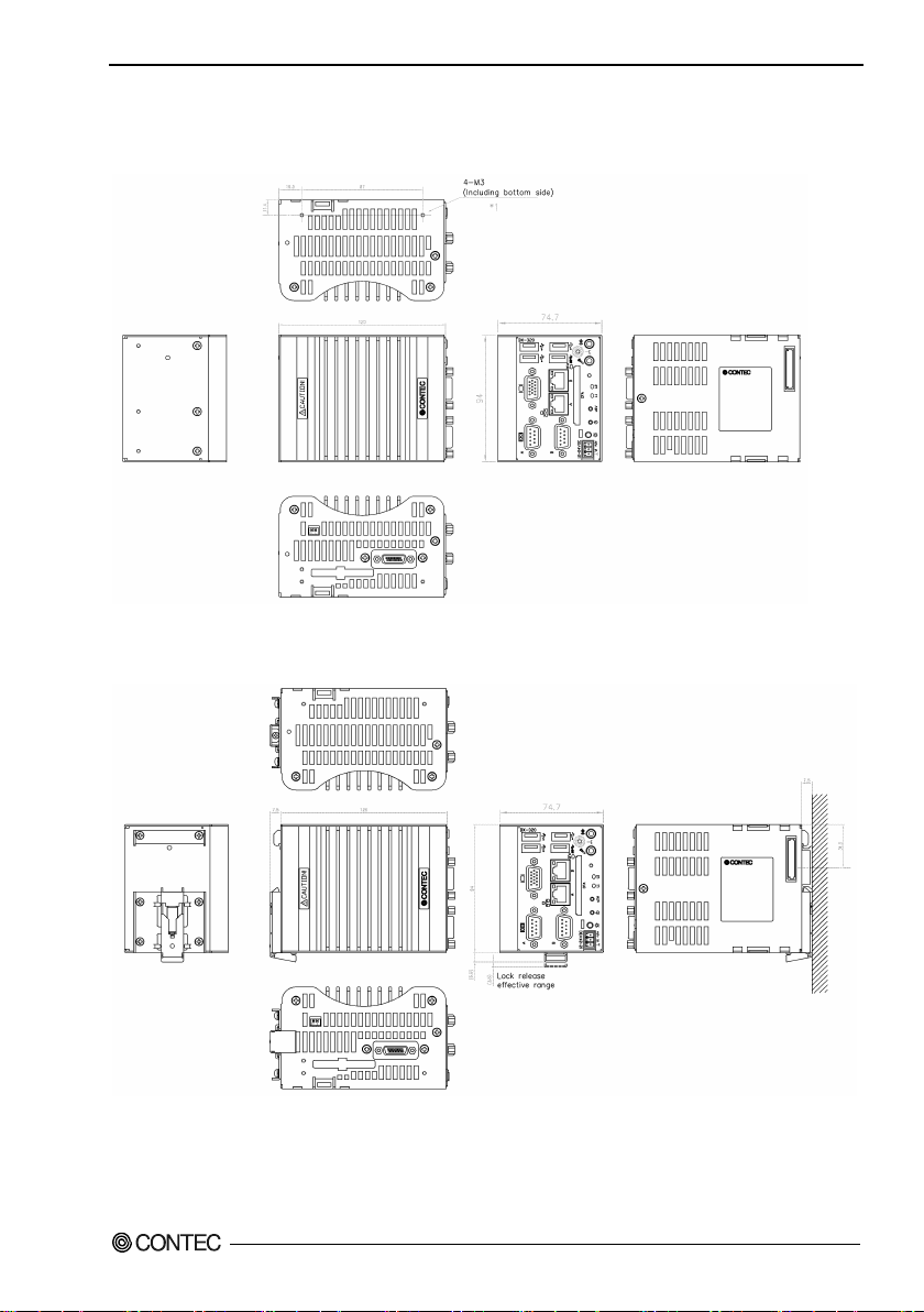
Physical Dimensions
BX-320-DCxxxxxx
*1: Ensure that the penetration depth (L) from the chassis surface to the screw tip is 3 mm or lower for the top and
bottom and 4 mm or lower for the back.
Figure 2.1. BX-320-DCxxxxxx (Including screw hole dimensions *1)
*2: To secure this product with the included fittings, use the included screws (M3x7). In other situations, use screws
with a penetration depth (L) from the chassis surface to the screw tip of 3 mm or lower.
Figure 2.2. BX-320-DCxxxxxx (When mounting the DIN rail installation metal fittings *2)
BX-320 User’s manu a l
13
Page 21

2. System Reference
BX-320 User’s manu a l
14
Page 22

3. Hardware Setup
CAUTION
3. Hardware Setup
Before Using t he Product for the First Time
Follow the next steps to set up this produ ct:
STEP1 By referr ing to the i n formati o n in t h is chapter , install, connect and set this product.
STEP2 Conn e ct cable s.
Connect the cable o f necessary external devices, such as keyboard and a display, to this
product using appropriate cables.
STEP3 Turn on th e pow er.
After verifying that you have correctly fol lowed steps 1 and 2, turn on the power.
If you find any abnorm a lity after t urning on the powe r, turn it off and check to see if the
setup has been perfo rmed properly.
STEP4 Set up BIOS.
By referring to Chapter 4, set up BIOS. This setup req ui res a keyboard and a display.
* Before using this product, be sure to execute "Restore Defaults" to initialize the BIOS
settings to their default values.
(See Chapter 4, "Save & Exit.")
- Be sur e t o c onnect the keyboard and mouse to it before turning the power on for t he first time .
- Be sure to connect the display before turning the power on. Connecting the display after turning the
power on may prevent it from being displayed properly.
BX-320 User’s manu a l
15
Page 23

3. Hardware Setup
CAUTION
Hardware Setup
- Before you start, be sure that the power is turned off.
- Remove only those screws that are expl ained . Do n ot m ov e any othe r s crew.
Inserting an Embedded CFast Card
CFast one card (Type1) can be attached. BX-320-DC7xxxxx come with CFast cards with the OS alre a dy
installed.
(1) Unscrew the single chassis securing countersunk screw in the figure below.
(2) Ins ert a C Fast card al l t he wa y into slot CFast2 on th e bottom of t his produ ct .
(3) Secure the CFast card re mo val preve ntion fitt i ng on the bottom of this product with the countersunk
screw.
*1 Attached screw (M3 x 6)
Figure 3.1. Installing a CFast card in slot CFast2
- Screw holes may be damaged if screws are tightened with a torque greater than the specified torque.
The specified tighteni ng torque is 5 - 6kgf⋅cm.
- If you use a CF a s t card other than the optio nal card, we cannot guaran tee the specifications of this
product. To use the product within its specifications, be sure to use the optional CFast card.
- To prevent potential damage caused by static elec tricity, take appr opriate anti-static measures (for
example, wearing an anti-static wr i stband) wh e n i n s ert i ng or removing the C Fast card.
- Insert the CFast Card face up.
- Do not tou c h t h e te r m i na l s on t h e CF ast card. Doing so may dama g e the card.
- Be careful not to mistake the orientation of the CFast card when inserting it. Also, do not use
exces si ve force w he n inserting the CFa st ca rd. Doing so may da mage the co nn e ctor.
- Do not dro p or other wi s e subject t h e CF ast card to strong im pacts bef ore insertion. Doi n g s o ma y
damage the card.
BX-320 User’s manu a l
16
Page 24
3. Hardware Setup
CAUTION
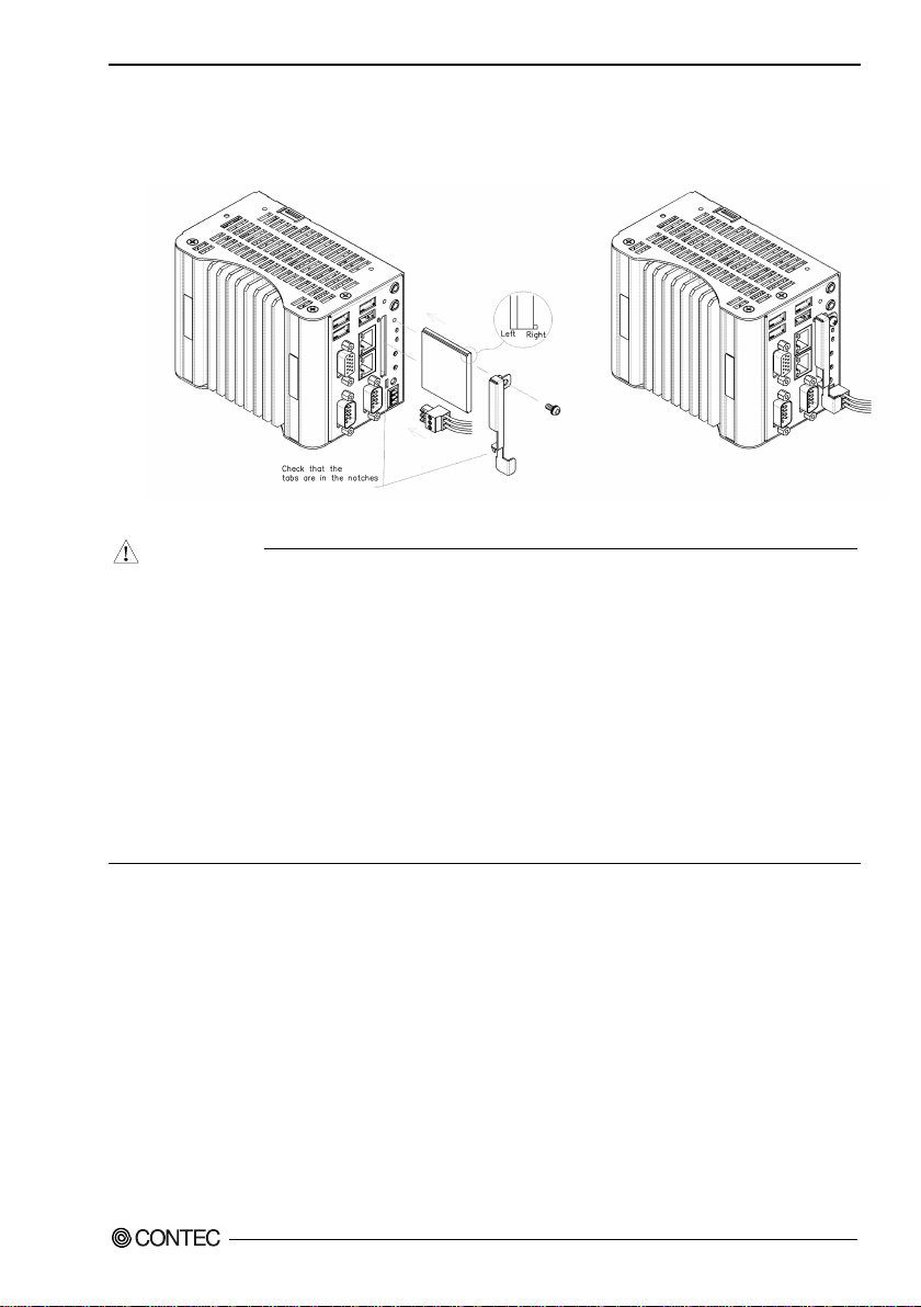
Installing a CFast card in slot CFast1
One CFast c ard (Type 1) c an be e quipped in slo t CFast1 on the f ront of this product.
(1) After inserting a CFas t Card, fasten the bundled CFast attachment fittings with a screw.
Figure 3.2. Attaching the CFast Attachment Fittings
- Screw holes may be damaged if screws are tightened with a torque greater than the specified torque.
The specified tightening torque is 5 - 6kgf⋅cm.
- If you use a CF a s t card other than the optional card, we cannot guaran tee the specifications of this
product. To use the product within its specifications, be sure to use the optional CFast card.
- To prevent poten tial damage caused by s tatic electricity, take appropriate anti-static measures (for
example, wearing an anti-static wr i stband) wh e n i n s ert i ng or removing the C Fast card.
- Insert the CFast Card face up.
- Do not tou c h t h e te r m i na l s on t h e CF ast card. Doing so may dama g e th e ca rd.
- Be careful not to mistak e the ori enta ti o n of the CFa st car d when inserting it. Also, do not use
exces si ve force w he n inserting the CFa st ca rd. Doing so may da mage the co nn e ctor.
- Do not dro p or other wi s e subject t h e CF ast card to strong im pacts bef ore insertion. Doi n g s o ma y
damage the card.
BX-320 User’s manu a l
17
Page 25
3. Hardware Setup
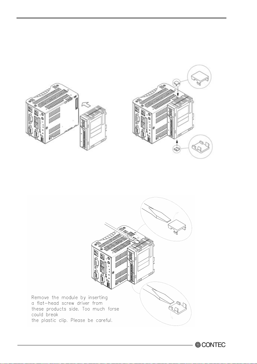
Mounting the Device Module
(1) Insert the stack hook by aligning it w ith the hook ins ertion inle t for the other device.
(2) Mount the module onto this product, using the bundled F&eIT module fixing parts.
(If a stac k connector protective cover is attac he d, the connection ope r ation should be per for med after
the cover is removed.)
Figure 3.3. Mounting the module
Removing the Module
(1) Remove the F&eIT module fixing parts f rom the top and bottom to detach the joined mod ules.
Figure 3.4. Removing the Module
BX-320 User’s manu a l
18
Page 26
3. Hardware Setup
CAUTION
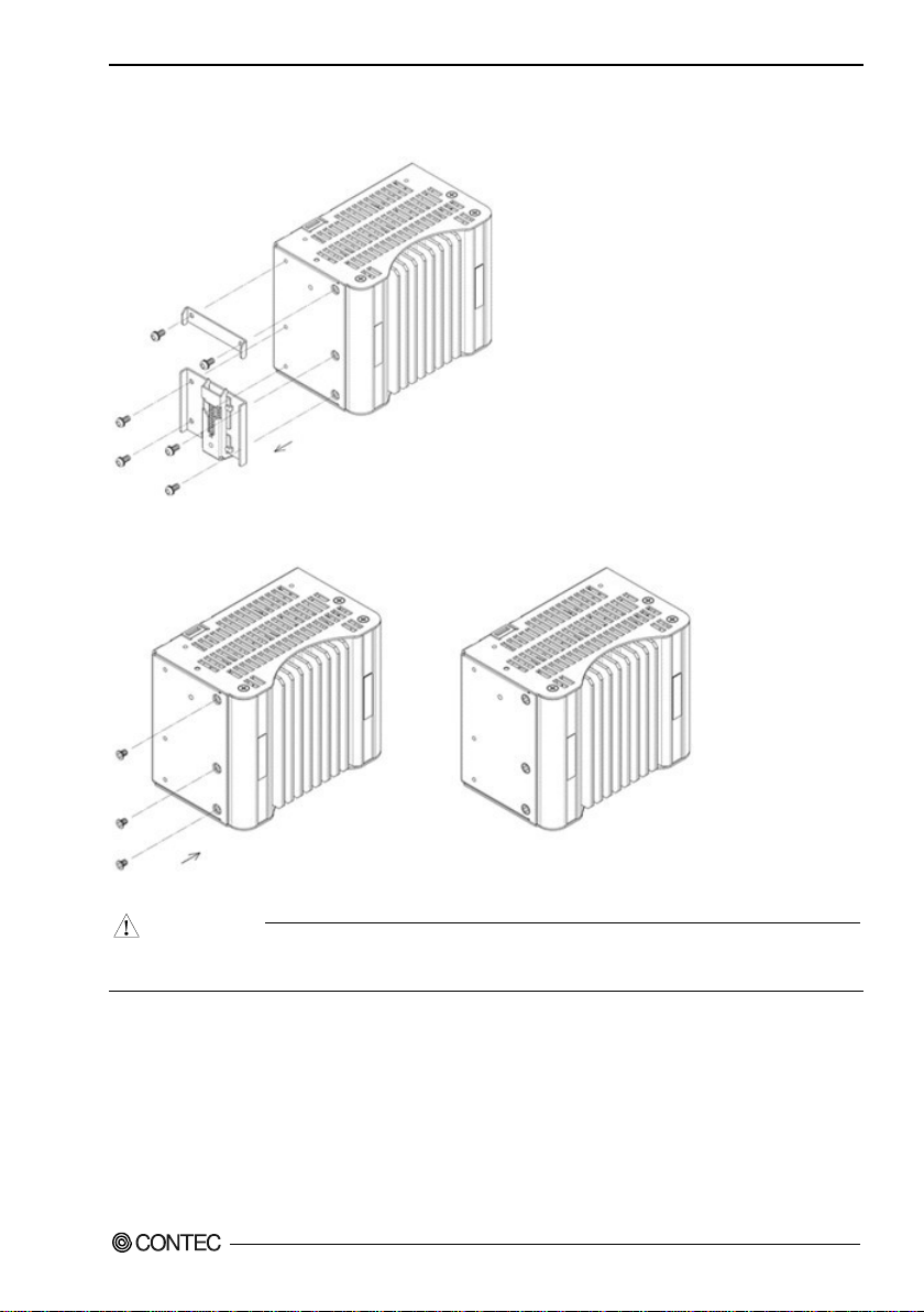
Removing a DIN Rail Installation Metal Fittings
(1) Remove the 6 screws f ound at t h e back of the main unit.
Figure 3.5. Removing a DIN Rail Installation Metal Fittings < 1 / 2 >
(2) Remove the bundled countersunk screws.
Figure 3.6. Removing a DIN Rail Installation Metal Fittings < 2 / 2 >
- Screw holes may be damaged if screws are tightened with a torque greater than the specified
BX-320 User’s manu a l
torque.The specified tightening torque is 5 - 6 kgf·cm.
19
Page 27
3. Hardware Setup
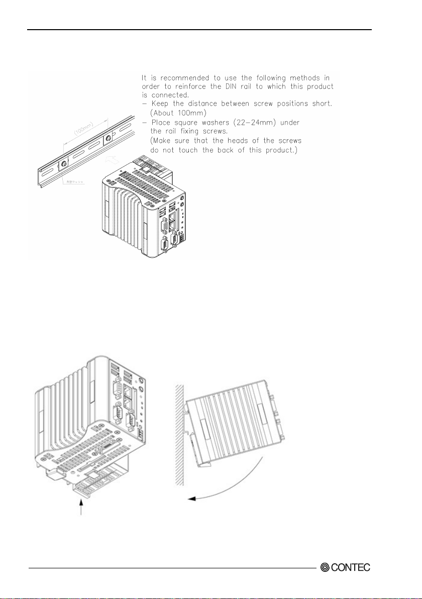
Mounting on a DIN rail installation metal fittings
(1) Check the DIN rail mounting location.
Figure 3.7. Mounting on a DIN rail < 1 / 2 >
(2) Remove the lock for connected device mo dules. When a device module is connected, if you lift up
the fixing hook with a flat-head screw driver, the fi xing hook ca n be locked. (This should be done on
all connected device modules.)
(3) Hook the unit (an object co ns isting of a controller and a module) from the upper part of the DIN rail,
and press the lower part of the unit onto the DIN rail.
If a devi c e m odu le is conne cted, the fixing hook w ill be locked automatically; the ref ore, the device
modul e can be atta ch e d with a sing le motion.
Figure 3.7. Mounting on a DIN rail < 2 / 2 >
BX-320 User’s manu a l
20
Page 28
3. Hardware Setup
C
AUTION
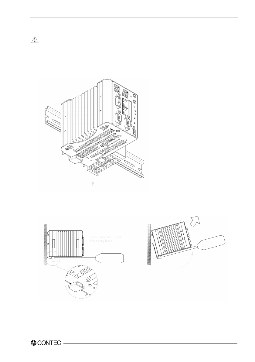
Removing from a DIN Rail
To disco nnect any conne cted device from the other modules, remove all the device modules which
are con n ec ted to thi s pr oduct, fr om the DIN rail beforeha nd.
(1) If a device module is connected, pul l down the fixing hook of the device module to unlock it.
(This should be done on all connecte d device modules.)
Figure 3.8. Removing the module from the DIN rail < 1 / 2 >
(2) With the fixing hook unlocked, if you insert a screw driver into the fitting in the position on the
figure and lift up this product, it c an be easily removed from the DIN rail.
Figure 3.8. Removing the module from the DIN rail < 2 / 2 >
BX-320 User’s manu a l
21
Page 29
3. Hardware Setup
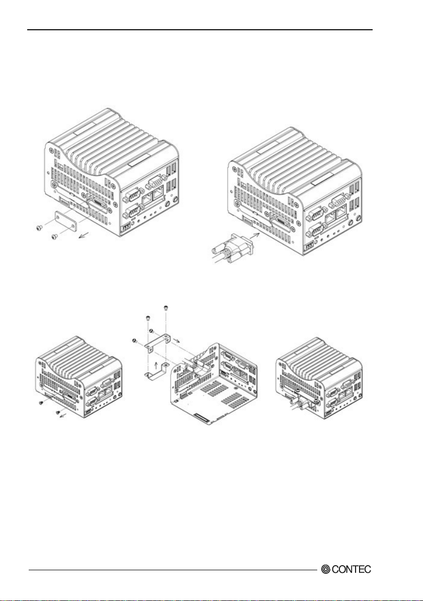
Securing the expansion connector cable and attaching the cover
You can conne ct this product to a CONTEC external exp ansion unit us ing the connector on the bot tom.
When the ca ble may be exposed to loads such as those from vibrations and impacts, secure the cable to
the con n ec tor with th e in cl uded ca bl e clamp as s ho w n in t he fi gu r e below (use the four incl ude d M3x7
screws).
Figure 3.9. Attaching the cable clamp
When not using the expansion connector, or when you need to preve nt worker s fr om accide nt a l l y
inserting objec ts into the conne ctor, att ach the included c onnector cover as shown in th e figure below.
Figure 3.10. Attaching t he connector cover
BX-320 User’s manu a l
22
Page 30
3. Hardware Setup
CAUTION
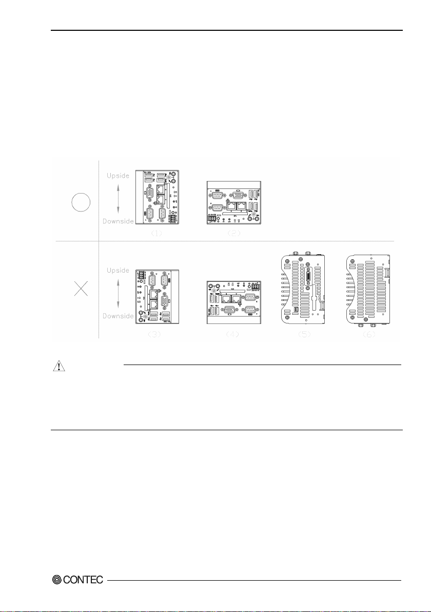
Installation Requirements
There are limits to the ambient temperature range depending on the inst allation orientation.
Be sure that the operating temperature is within the range specified in the installation environment
requiremen t by making space between the pr oduct and device that generates heat or exhaust air.
Installabl e dire ctio n s at opera tin g temp era ture 0 - +50°C: (1)
(When using 1000BAS E-T: 0 - +45°C)
Installabl e dire ctio n s at opera tin g temp era ture 0 - +35°C: (2)
(When using 1000BAS E-T: 0 - +30°C)
Installable directions that is unusable: (3), (4), ( 5), (6)
Figure 3.11. Installation Orientation
- Note that even though the ambient temperature is within the specified range, an operational
- When the installation orientation is (1) and the ventilation holes on the bottom may become blocked,
BX-320 User’s manu a l
malfunction may occur if there is other device generating high heat; the radiation will influence the
product to increase its temperature.
use the included rubber feet.
23
Page 31

3. Hardware Setup
Distances between this product and its vicinity
Figure 3.12. Distances between this product and its vicinity
BX-320 User’s manu a l
24
Page 32

3. Hardware Setup
CAUTION
- Wall temperatures should be within the guaranteed operating temperature range of the product.
- Adjust the air flow so as not to allow waste heat from the product to accumulate around the product.
- Do not install this product in completely sealed spaces, except when it is possible to adjust the
internal temperature using an ai r conditioner or simil ar eq uip ment. Temperature increase caused by
long-te r m usage may r e su l t in operational ma l fu n ction or ot he r problem s.
BX-320 User’s manu a l
25
Page 33

3. Hardware Setup
Operating temperature
In this product, the operating temperature is decided from the multiple measurement points as shown
below. When making us e o f th e product, t he air cu rrent shou ld be adju s te d to preve nt tha t all the
temperatures measured at the measurement points exceed the specified temperature.
Figure 3.13. Operating temperature
BX-320 User’s manu a l
26
Page 34

4. BIOS Setup
4. BIOS Set up
Introduction
This chapter discusses American Megatr ends’s (AMI) Setup program built into the FLASH ROM BIOS.
The Setup program allows users to modify the basic system configuration. This special information is
then stored in FLASH ROM so that it retains the Setup inf ormation when the power is turned off.
The rest of this chapter is intended to guide you through the process of configuring your system using
Setup.
Starting Se tup
The AMI BIOS is immed iately act ivated when you first power on the computer . The BIOS reads the
system information contained in the FLASH ROM and begins the proc es s of chec king out the system and
configuring it. When it finishes , the BIOS wil l se ek an operating system on one of the disks and then
launch an d turn contro l over to the operating sys tem.
While the BIOS is in cont rol, th e Se tu p progra m can be acti va te d i n on e of two wa y s:
1 By pre ssing <Del> or <ESC> immediately after switching the system on, or
2 By pressing the <Del> or <ESC> key when the fo llowing message appears briefly at t he bottom of
the screen during the POST (Power On Self-Test).
Press <DEL> ot <ESC> to enter SETUP.
If the message disappears before you respond and you still wish to enter Setup, restart the system to try
again by turning it OFF then ON on the system case. You may also restart by simult ane ously pressing
<Ctrl>, <Alt>, and <Delete> keys.
BX-320 User’s manu a l
27
Page 35

4. BIOS Setup
Key
Function
Up Arrow
Move to the previous item
Down Arrow
Move to the next item
Left Arrow
Move to the item on the left (menu bar)
Right Arrow
Move to the item on the right (menu bar)
Esc
Move Enter
Move to the item you desired
+ key
Increase the numeric value or make changes
- key
Decrease the numeric value or make changes
F1 key
F2 key
F3 key
F4 key
Using Setup
In general, you use the a rrow keys to highlight items, press <Enter> to select, use the Page U p and
PageDow n keys to change e ntries, press <F1> for he lp and press <Esc> to quit. The following table
provides more detail about how to navigate in the Setup program using the keyboard.
Table 4.1. Using Se tup
Main Menu: Quit without saving changes
Submenus: Exit Current page to the next higher level menu
General help on Setup navigation keys
Load the previous settings.
Load the optimal defaults from the BIOS default table.
Save all the changed settings to the FLASH ROM and exit
An attention when using Windows 10
The attention at the time of making default configuration by BIOS other than making OS reinstallation
(recovery). Please be sure to use t he CSM Support set in an Advanced set for [Dis a bled] after Restore
Defaults (Load Optimize Defaults), setting it up.
Getting Help
Press F 1 to pop up a small help window th at des cribes the appropri ate keys to use and the possibl e
selections for the highlighted item. To exit the Help Window press <Esc> or the F1 key again.
In Case of Problems
If you cannot boot the computer after using Setup to change and save system se tt ings, the computer will
have to be repaired. I t is safest not to c hange system settings you do not fully understand. Therefore, it is
strongly recommended that you do not change any of the default settings for the chipset. These defaults
have been selected with sufficient consideration by the AMI and system manufacturers to ensure
maximum performance and reliability. Even changing the chipset settings sli ghtly can result in an
unavo idable nee d f or repair s .
A Final Note About Setup
The information in this chapter is subject to change without notice.
BX-320 User’s manu a l
28
Page 36

4. BIOS Setup
Aptio Setup Utility
- Copyright (C) 2016 American Megatrends, Inc.
Main
Advanced
Chipset
Security
Boot
Save & Exit
BIOS Information
BIOS Vendor American Megatrends
Core Version 5.010
Compliency UEFI 2.4; PI 1.3
Project Version B320C 0.01 x64
Build Data and Time 03/31/2016 11:31:22
CPU Configuration
Microcode Pat ch 905
BayTrail SoC D0 Stepping
Memory Information
Total Memory 4096 MB (DDR3U)
GOP Information
Intel(R) GOP Dri ver [N/A]
TXE Information
Sec RC Version 00.05.00.00
TXE FW Version 01.01.00.1089
System Language [English]
System Date [Week Day MM/DD/YYYY]
System Time [HH:MM:SS]
Access Level Administrator
→←:Select Screen
↑↓:Select Item
Enter:Select
+/-:Change Opt.
F1:General Help
F2:Previous Values
F3:Optimized Defaults
F4:Save & Exit
ESC:Exit
Version x.xx.xxxx. Copyright (C) 20xx American Megatrends, Inc.
Main Menu
When the setup program (Aptio Startup Utility) is started, the main me nu wi ll be di spla yed . Na viga te
through the various tabs by pressing the right and left arrow keys.
Figure 4.1. Main Manu
Setup Items
The selectable tabs are as follows.
Main
View the basic system structure , and configure the languag e s ettings and the date and time settings.
Advanced
Specify the detailed functions that can be set on the system used.
Chipset
Specify the detailed functions that can be set on the system used.
Security
Set the password to be used to protect the security of the system.
Boot
Configure the settings relate d to how the system w ill boot.
Save & Exit
Load/save setu p item s and exit the setup menu.
BX-320 User’s manu a l
29
Page 37

4. BIOS Setup
Item
Indication example
Explanation
BIOS Vendor
American Megatrends
Displays the BIOS manufacturer.
Core Ve rsion
5.010
Displays the BIOS core version.
Compliency
UEFI 2.4; PI 1.3
Displays the UEFI version.
Project Version
B320C 0.01 x64
Displays the BIOS version.
Build Data and Time
03/31/2016 11:31:22
Displays the BIOS creation date and time.
Access Level
Administrator
Displays the access rights level.
date
Sys te m Ti me
Hour : Minute : Second
Set the system time
Main
View the basic sys tem structure. The following items are displayed.
Table 4. 2. Indication item of the main menu
This table shows the selections that you can make on the Main Menu.
Table 4. 3. Main Menu Selections
Item Options Description
System Date Week Da y Month / Day / Year
Set the system date. Note that the ‘Day’
automatically changes when you set the
BX-320 User’s manu a l
30
Page 38

4. BIOS Setup
Aptio Setup Utility - Copyright (C) 20xx American Megatrends, Inc.
Main
Advanced
Chipset
Security
Boot
Save & Exit
▶ ACPI Settings
▶ Super IO Configuration
▶ H/W Monitor
▶ CPU Configuration
▶ PPM
Configuration
▶ SATA Configuration
▶ CSM Configuration
→←:Select Screen
↑↓:Select Item
Enter:Select
+/-:Change Opt.
F1:General Help
F2:Previous Values
F3:Optimized Defaults
F4:Save & Exit
ESC:Exit
Version x.xx.xxxx. Copyright (C) 20xx American Megatrends, Inc.
Advanced
Specify the detailed system functions. The fol lowing items are avail able.
Figure 4.2. Advanced Manu
ACPI Setting s
Configure the ACPI settings.
Super I O Conf iguration
Configure the Supe r IO settings.
H/W Monitor
View such inform ation as the CPU temper ature.
CPU Configuration
Configure the CPU settings.
PPM Configuration
Configure the power saving function settings.
SATA Confi guration
Configure the SATA controller setting s.
CSM Configuration
Configure such settings as the boot options .
BX-320 User’s manu a l
31
Page 39

4. BIOS Setup
Aptio Setup Utility - Copyright (C) 20xx American Megatrends, Inc.
Advanced
ACPI Settings
Enable Hibernation [Enabled]
ACPI Sleep State [S3 (Suspend to RAM)]
Wake On LAN/RI Control on S5 [Disabled]
Resume On RTC Alarm [Disabled]
→←:Select Screen
↑↓:Select Item
Enter:Select
+/-:Change Opt.
F1:General Help
F2:Previous Values
F3:Optimized Defaults
F4:Save & Exit
ESC:Exit
Version x.xx.xxxx. Copyright (C) 20xx American Megatrends, Inc.
Item
Option
Description
Disabled
Enabled
S3 (Suspend to RAM)
separately.
on.
Item
Option
Description
RTC Wake up Day
1-31
Sets the day the system will automatically turn on.
RTC Wake up Hour
0-23
Sets the time the system will automatically turn on.
RTC Wake up Minute
0-59
Sets the minute the system will automatically turn on.
RTC Wake up Second
0-59
Sets the second the system will automatically turn on.
ACPI Settings
Configure the settings for ACPI power management.
Figure 4.3. ACPI Settings
Table 4.4. ACPI Settings
Enable Hibernation
ACPI Sleep State
Wake On LAN/RI Control on
S5
Resume on RTC Alarm
Table 4.5. Resume On RTC Alarm (Only Available When "Enabl ed" I s Selected)
BX-320 User’s manu a l
32
Suspend Disabled
Disabled
Enabled
Disabled
Enabled
Configure the Hibernation settings.
Configure the Sleep State settings.
Set the Wake on LAN/Resume on Ring
functions. These functions cannot be set
Enable or disable the function for
automatically turning on the system at the
specified date and time. When enabled,
use the following items to set the date and
time the system will automatically turn
Page 40

4. BIOS Setup
Aptio Setup Utility - Copyright (C) 20xx American Megatrends, Inc.
Advanced
Super IO Configuration
Super IO Chip NCT6102D
▶ Serial Port A Configuration
▶ Serial Port B Configuration
→←:Select Screen
↑↓:Select Item
Enter:Select
+/-:Change Opt.
F1:General Help
F2:Previous Values
F3:Optimized Defaults
F4:Save & Exit
ESC:Exit
Version x.xx.xxxx. Copyright (C) 20xx American Megatrends, Inc.
Item
Option
Description
Configuration
Configuration
Disabled
Enabled
Configure the operation settings for serial
port A.
IO=3F8h; IRQ=4;
IO=2D0-2F8h; IRQ=3,4,5,6;
Super IO Configuration
Configure the operation settings for Super IO.
Figure 4.4. Super IO Configuration
Table 4.6. Super IO Configuration
Serial Port A
Serial Port B
Table 4.7. Serial Port A Configuration
Item Option Description
Serial Port
Change Settings
BX-320 User’s manu a l
Refer to Table 4.7. -
Refer to Table 4.8. -
IO=2A0h; IRQ=3,4,5,6;
IO=2E8h; IRQ=3,4,5,6;
IO=2F8h; IRQ=3,4,5,6;
IO=3E8h; IRQ=3,4,5,6;
IO=3F8h; IRQ=3,4,5,6;
Do not change this setting.
33
Page 41

4. BIOS Setup
Item
Option
Description
Disabled
Enabled
Configure the operation settings for serial
port B.
IO=2F8h; IRQ=3;
IO=2F8h; IRQ=3,4,5,6,7,9,10,11,12;
Table4.8. Serial Port B Configuration
Serial Port
Change Settings
IO=3F8h; IRQ=3,4,5,6,7,9,10,11,12;
IO=2F8h; IRQ=3,4,5,6,7,9,10,11,12;
IO=3E8h; IRQ=3,4,5,6,7,9,10,11,12;
Do not change this setting.
BX-320 User’s manu a l
34
Page 42

4. BIOS Setup
Aptio Setup Utility - Copyright (C) 20xx American Megatrends, Inc.
Advanced
Pc Health Status
System temperature : +35 C
CPU temperature : +42 C
VCORE : +0.888 V
+1.8V : +1.760 V
+5V : +5.024 V
+5VSB : +5.056 V
+3.3 VSB : +3.312 V
+3.3 VCC : +3.296 V
VBAT : +3.216 V
→←:Select Screen
↑↓:Select Item
Enter:Select
+/-:Change Opt.
F1:General Help
F2:Previous Values
F3:Optimized Defaults
F4:Save & Exit
ESC:Exit
Version x.xx.xxxx. Copyright (C) 20xx American Megatrends, Inc.
H/W Monitor
View hardware monitor information such as the CPU temperature.
Figure 4.5. H/W Monitor (Actual Display May Vary.)
BX-320 User’s manu a l
35
Page 43

4. BIOS Setup
Aptio Setup Utility - Copyright (C) 20xx American Megatrends, Inc.
Advanced
CPU Configuration
▶
Socket 0 CPU Information
CPU Speed 1918MHz
64-bit Supported
Execute Disable Bit [Enabled]
Intel Virtualization Technology [Disabled]
→←
:Select Screen
↑↓:Select Item
Enter:Select
+/
-:Change Opt.
F1:General Help
F2:Previous Values
F3:Optimized Defaults
F4:Save & Exit
ESC:Exit
Version x.xx.xxxx. Copyright (C) 20xx American Megatrends, Inc.
Item
Option
Description
Enabled
Technol ogy
Disabled
Enabled
CPU Configuration
Configure the operation settings for CPU.
Figure 4.6. CPU Configuration
Table 4.9. CPU Configuration
Execute Disable Bit
Intel Virtualization
BX-320 User’s manu a l
36
Disabled
Do not change this setting.
Do not change this setting.
Page 44

4. BIOS Setup
Aptio Setup Utility - Copyright (C) 20xx American Megatrends, Inc.
Advanced
PPM Configuration
EIST [Disabled]
CPU C-State Report [Disabled]
S0ix [Disabled]
→←:Select Screen
↑↓:Select Item
Enter:Select
+/-:Change Opt.
F1:General Help
F2:Previous Values
F3:Optimized Defaults
F4:Save & Exit
ESC:Exit
Version x.xx.xxxx. Copyright (C) 20xx American Megatrends, Inc.
Item
Option
Description
Disabled
Enabled
Enabled
Enabled
PPM Configuration
Configure the power saving function settings.
Figure 4.7. PPM Configuration
Table 4.10. PPM Configuration
EIST
CPU C-State Report
SOix
BX-320 User’s manu a l
Disabled
Disabled
Do not change this setting.
Do not change this setting.
Do not change this setting.
37
Page 45

4. BIOS Setup
Aptio Setup Utility - Copyright (C) 20xx American Megatrends, Inc.
Advanced
SATA Configration
Serial-ATA (SATA) [Enabled]
SATA Test Mode [Disabled]
SATA Speed Support
[Gen2]
SATA ODD Port [No ODD]
SATA Mode [AHCI Mode]
Serial-ATA Port 0 [Enabled]
Serial-ATA Port 1 [Enabled]
SATA Port 0
xxxx
SATA Port 1
xxxx
→←:Select Screen
↑↓:Select Item
Enter:Select
+/-:Change Opt.
F1:General Help
F2:Previous Values
F3:Optimized Defaults
F4:Save & Exit
ESC:Exit
Version x.xx.xxxx. Copyright (C) 20xx American Megatrends, Inc.
Item
Option
Description
CFast drive to become unrecognized.
Disabled
Gen1
Gen2
Port0 ODD
No ODD
be reinstalled.
Enabled
Disabled
port0.
Enabled
Disabled
Configure the operation settings for SATA
port1.
SATA Configuration
Configure the SATA controller settings.
Figure 4.8. SATA Configuration
Table 4.11. SATA Configuration
Serial-ATA (SATA)
SATA Test Mode
SATA Spe ed Support
SATA ODD Port
SATA Mode
Serial-ATA Port 0
Serial-ATA Port 1
BX-320 User’s manu a l
38
Enabled
Disabled
Enabled
Port1 ODD
IDE Mode
AHCI Mode
Configure the SATA controller operation
settings. Changing this setting will cause the
Do not change this setting.
Do not change this setting.
Do not change this setting.
Specify the SATA device mode.
Changing this setting will re quire the OS to
Configure the operation settings for SATA
Page 46

4. BIOS Setup
Aptio Setup Utility
- Copyright (C) 20xx American Megatrends, Inc.
Advanced
Compatibility Support Module Configuration
CSM Support [Enabled]
CSM16 Module Version xx.xx
GateA20 Active [Upon Request]
Option ROM Messages [Force BIOS]
Boot Option filter [UEFI and Legacy]
Option ROM execution
Storage [UEFI]
Video [Legacy]
Other PCI devices [UEFI]
→←:Select Screen
↑↓:Select Item
Enter:Select
+/-:Change Opt.
F1:General Help
F2:Previous Values
F3:Optimized Defaults
F4:Save & Exit
ESC:Exit
Version x.xx.xxxx. Copyright (C) 20xx American Megatrends, Inc.
Item
Option
Description
Enabled
Upon Request
Always
Force BIOS
Keep Current
UEFI and Le gacy
UEFI only
Legacy
Legacy
Legacy
CSM Configuration
Configure settings a s s ociated wit h the CSM (Compatibility Support Module), such as Option ROM
execution. For Windows 10 64bit model, set CSM Support to [Disabled].
Figure 4.9. CSM Configuration
Table 4.12. SM Configuration
CSM Support
GateA20 Active
Option ROM Message
Boot option filte r
Storage
Video
Other PCI devices
BX-320 User’s manu a l
Disabled
Legacy only
Do not la unch
UEFI
Do not la unch
UEFI
Do not la unch
UEFI
Do not change this setting.
Do not change this setting.
Do not change this setting.
Do not cha nge this setting.
Do not change this setting.
Do not change this setting.
Do not change this setting.
39
Page 47

4. BIOS Setup
Aptio Setup Utility - Copyright (C) 20
xx American Megatrends, Inc.
Main
Advanced
Chipset
Boot
Security
Save & Exit
▶
North Bridge
▶
South Bridge
→←:Select Screen
↑↓:Select Item
Enter:Select
+/-:Change Opt.
F1:General Help
F2:Previous Values
F3:Optimized Defaults
F4:Save & Exit
ESC:Exit
Version x.xx.xxxx. Copyright (C) 20xx American Megatrends, Inc.
Chipset
Specify the detailed chipset functions.
Figure 4.10. Chipset
The following items are available.
North Bridge
Configure the operation settings for North Bridge.
South B ri dge
Configure the operation settings for South Bridge.
BX-320 User’s manu a l
40
Page 48

4. BIOS Setup
Aptio Setup Utility - Copyright (C) 20xx American Megatrends, Inc.
Chipset
▶
Intel IGD Configuration
▶
LCD Control
Memory Information
Total Memory 4096 MB (DDR3U)
Memory Slot 0 4096 MB (DDR3U)
Max TOLUD [3 GB]
Bypass SPD Detect [Disable]
→←:Select Screen
↑↓:Select Item
Enter:Select
+/-:Change Opt.
F1:General Help
F2:Previous Values
F3:Optimized Defaults
F4:Save & Exit
ESC:Exit
Version x.xx.xxxx. Copyright (C) 20xx American Megatrends, Inc.
Item
Option
Description
Intel IGD Configuration
Refer to Table 4.14.
-
3GB
Disable
Enabled
North Bridge
Configure the operatio n s e ttings for No rth Bridge.
Figure 4.11. North Bridge
Table 4.13. North Br idg e
2 GB
Max TOLUD
Bypass SPD Detect
2.25 GB
2.5 GB
2.75 GB
BX-320 User’s manu a l
Do not change this setting.
Do not change this setting.
41
Page 49

4. BIOS Setup
Aptio Setup Utility - Copyright (C) 20xx American Megatrends, Inc.
Chipset
GOP Configuration
GOP Driver [Enabled]
Intel IGD Configuration
PAVC [LITE Mode]
DVMT Pre-Allocated [64M]
DVMT Total Gfx Mem [256M]
Aperture Size [256M]
GTT Size [2MB]
→←:Select Screen
↑↓:Select Item
Enter:Select
+/-:Change Opt.
F1:General Help
F2:Previous Values
F3:Optimized Defaults
F4:Save & Exit
ESC:Exit
Version x.xx.xxxx. Copyright (C) 20xx American Megatrends, Inc.
Item
Option
Description
Disalbed
SERPENT Mode
512MB
256MB
Intel IGD Configuration
Configure how memory will be used when using the graphic function.
Leave these settings as configured before shipment.
Figure 4.12. In t e l GO P Configuration
Table 4.14. Intel GOP Configuration
GOP Driver
PAVC
DVMT Pre-Allocated
DVMT Total Gfx Mem
BX-320 User’s manu a l
42
Enabled
Disabled
LITE Mode
64MB
96MB
128MB
160MB
192MB
224MB
256MB
288MB
320MB
352MB
416MB
448MB
128MB
Do not change this setting.
Do not change this setting.
Do not change this setting.
Do not change this setting.
Page 50

4. BIOS Setup
Item
Option
Description
MAX
512MB
2MB
128MB
Aperture Size
256MB
Do not change this setting.
GTT Size
1MB
Do not change this setting.
BX-320 User’s manu a l
43
Page 51

4. BIOS Setup
Aptio Setup Utility - Copyright (C) 20xx American Megatrends, Inc.
Chipset
▶ Azalia HD Audio
▶ USB Configuration
▶ LAN Configuration
High Precision Timer [Enabled]
Restore AC Power Loss [Power On]
Serial IRQ Mode [Continuous]
→←:Select Screen
↑↓:Select Item
Enter:Select
+/-:Change Opt.
F1:General Help
F2:Previous Values
F3:Optimized Defaults
F4:Save & Exit
ESC:Exit
Version x.xx.xxxx. Copyright (C) 20xx American Megatrends, Inc.
Item
Option
Description
Refer to
Table 4.16.
Table 4.17.
Refer to
Table 4.18.
Enabled
Disabled
start the next time the power supply starts.
Continuous
South Bridge Configuration
Configure the South B ridge settings.
Figure 4.13. PCH-IO Configuration
Table 4.15. PCH-IO Configuration
Azalia HD Audio
USB Confi guration
LAN Configuration
High Precision Timer
Restore AC Powe r Loss
Serial IRQ Mode
BX-320 User’s manu a l
44
Refer to
Power Off
Power On
Last State
Quiet
Configure the high-precision event timer settings.
Set whether to start the system at the same time the power supply
starts.
Power OFF:
Press the power button to start the system. The system does not
start at the same time the power supply starts.
Power ON:
The system will start at the same time the power supply starts.
Last State:
If the power is turned off while the system is on, the system will
Do not change this setting.
-
-
-
Page 52

4. BIOS Setup
Aptio Setup Utility - Copyright (C) 20xx American Megatrends, Inc.
Chipset
Audio Configuration
Audio Controller [Enabled]
→←:Select Screen
↑↓:Select Item
Enter:Select
+/-:Change Opt.
F1:General Help
F2:Previous Values
F3:Optimized Defaults
F4:Save & Exit
ESC:Exit
Version x.xx.xxxx. Copyright (C) 20xx American Megatrends, Inc.
Item
Option
Description
Azalia HD Audio Configuration
Configure the Azalia HD Audio settings.
Figure 4.14. Azalia HD Audio Configuration
Table 4.16. Azalia HD Audio Configuration
Display Port Audio C odec
Disabled
Enabled
BX-320 User’s manu a l
Configure the Audio Controller settings.
45
Page 53

4. BIOS Setup
Aptio Setup Utility - Copyright (C) 20xx American Megatrends, Inc.
Chipset
USB Configuration
USB Module Version 10
USB Devices:
1 Keyboard, 1 Mouse, 1 Hub
Legacy USB Support [Enable]
XHCI Hand-off
[Enable]
EHCI Hand-off [Disabled]
USB Mass Storege Driver Support [Enable]
USB hardware delays and time-outs:
Device power-up delay [Auto]
USB Overcurrent [Disabled]
OS Selection [Windows 7]
USB 3.0 (XHCI) Support [Enabled]
USB2 Link Power Management [Disabled]
USB 2.0 (EHCI) Support [Disabled]
→←:Select Screen
↑↓:Select Item
Enter:Select
+/-:Change Opt.
F1:General Help
F2:Previous Values
F3:Optimized Defaults
F4:Save & Exit
ESC:Exit
Version x.xx.xxxx. Copyright (C) 20xx American Megatrends, Inc.
Item
Option
Description
Enabled
Auto
Configure whet her USB keyboards and similar
systems (such as MS-DOS).
Enabled
Disabled
Disabled
Enabled
Disabled
Enabled
Configure the USB storage s upport settings with
BIOS.
Device power-up de lay
Auto
Manual
Disabled
Windows 8.X
Windows 7
Configure the USB 3.0 settings.
Windows 7.
Enabled
Disabled
will prevent all USB ports from operating.
USB Configuration
Configure the USB settings.
Figure 4.15. USB Configuration
Table 4.17. USB Configuration
Legacy USB Support
XHCI Hand-off
EHCI Hand-off
USB Mass Storage Driver Support
USB Overcurrent
OS Selection
USB3.0 (XHCI) Support
USB2 Link Power Management
USB2.0 (EHCI) Support
BX-320 User’s manu a l
46
Disabled
Enabled
Android
Enabled
Disabled
Smart Auto
Disabled
Enabled
devices will be usable with legacy operating
Do not change this setting.
Do not change this setting.
Do not change this setting.
Do not change this setting.
Do not change this setting.
This should normally be set to Enabled.
Set to Smart Auto to set up a USB 3.0 driver in
Do not change this setting.
Do not change this setting. Setting to Disabled
Page 54

4. BIOS Setup
Aptio Setup Utility - Copyright (C) 20xx American Megatrends, Inc.
Chipset
LAN Configuration
Onboard LAN A Controller [Enabled]
Onboard LAN B Controller [Enabled]
PXE Boot [UEFI]
→←:Select Screen
↑↓:Select Item
Enter:Select
+/-:Change Opt.
F1:General Help
F2:Previous Values
F3:Optimized Defaults
F4:Save & Exit
ESC:Exit
Version x.xx.xxxx. Copyright (C) 20xx American Megatrends, Inc.
Item
Option
Description
Controller
Controller
Enabled
Disabled
Do not launch
Legacy
LAN Configuration
Configure the LAN settings.
Figure 4.16. LAN Configuration
Table 4.18. LAN Configuration
Onboard LAN A
Onboard LAN B
PXE Boot
30B
BX-320 User’s manu a l
Enabled
UEFI
Can not change this setting.
Configure the LAN B Controller settings.
Configure the PXE boot settings.
47
Page 55

4. BIOS Setup
Aptio Setup Utility - Copyright (C) 20
xx American Megatrends, Inc.
Main
Advanced
Chipset
Security
Boot
Save & Exit
Password Description
If ONLY the Administrator’s password is set ,
then this only limits access to Setup and is
only asked for when entering Setup.
If ONLY the user’s password is set , then this
is a power on password and must be entered to
boot or enter Setup. In Setup the User will
have Administrator rights.
The password length must be
In the following range:
Minimum length 3
Maximum length 20
Administrator Password
User Password
▶
Secure Boot menu
→←:Select Screen
↑↓:Select Item
Enter:Select
+/-:Change Opt.
F1:General Help
F2:Previous Values
F3:Optimized Defaults
F4:Save & Exit
ESC:Exit
Version x.xx.xxxx. Copyright (C) 20xx American Megatrends, Inc.
Administrator Password
Create New Password
[**** ]
Confirm Ne w Password
[**** ]
User Password
Create New Password
[**** ]
Confirm Ne w Password
[**** ]
Security
Configure the security of the system settings.
Figure 4.17. Security
Admi ni str a tor Pas s wor d
Set the A d ministrator Pas s word.
Press Enter to display the following screen for entering the password.
Enter a password at le ast 3 characters long twice.
To disable the password, enter the Administrator Password entry screen again.
User Password
Set the user password.
Press Enter to display the following screen for entering the password.
Enter a password at le ast 3 characters long twice.
To disable the password, enter the Administrator Password entry screen again.
BX-320 User’s manu a l
48
Page 56

4. BIOS Setup
CAUTION
Secure Boot menu
It is displ ayed wh e n CS M Support i s set as Disabl e d.
Leave these settings as configured before shipment.
Be care fu l t o n ot forget the passwor d . If y ou fo r g et t he pa s s w ord, the pr oduct will ha v e t o b e re paired
at an extra cost.
BX-320 User’s manu a l
49
Page 57

4. BIOS Setup
Aptio Setup Utility - Copyright (C) 20xx American Megatrends, Inc.
Main
Advanced
Chipset
Security
Boot
Save & Exit
System Mode Setup
Secure Boot Not Active
Vendor Keys Not Active
Secure Boot [Enabled]
Secure Boot Mode [Standard]
▶
Key Management
→←:Select Screen
↑↓:Select Item
Enter:Select
+/-:Change Opt.
F1:General Help
F2:Previous Values
F3:Optimized Defaults
F4:Save & Exit
ESC:Exit
Version x.xx.xxxx. Copyright (C) 20xx American Megatrends, Inc.
Item
Option
Description
Custom
Secure Boot menu
Configure the Secure Boot settings.
Leave these settings as configured before shipment.
Figure 4.18. Secure Boot
Table 4.19. Secure Boot
Secure Boot
Secure Boot Mode
Disabled
Enabled
Standard
Do not cha nge this setting.
Do not change this setting.
BX-320 User’s manu a l
50
Page 58

4. BIOS Setup
Aptio Setup Utility - Copyright (C) 20xx American Megatrends, Inc.
Main
Advanced
Chipset
Security
Boot
Save & Exit
Boot Configuration
Setup Prompt Timeout 1
Bootup NumLock State [On]
Quiet Boot [Disabled]
Fast Boot [Disabled]
Boot Option Priorities
Boot Option #1 [xxxxxxxx]
Boot Option #2 [xxxxxxxx]
Boot Option #3 [xxxxxxxx]
CD/DVD ROM Drive BBS Priorities
Hard Drive BBS Priorities
Floppy Drive BBS Priorities
→←:Select Screen
↑↓:Select Item
Enter:Select
+/-:Change Opt.
F1:General Help
F2:Previous Values
F3:Optimized Defaults
F4:Save & Exit
ESC:Exit
Version x.xx.xxxx. Copyright (C) 20xx American Megatrends, Inc.
Item
Option
Description
Set the standby time for BIOS Setup <DEL>
Unit : [second]
State
On
Off
starts.
Disabled
Enabled
Disabled
Enabled
XXXXXXXX
(Specify any device)
Set the start order of the connected USB
floppy dri ves.*1
CD/DVD ROM Drive
BBS Priorities
XXXXXXXX
(Specify any device)
Set the start order of the connected CD/DVD
drives. *1
Priorities
(Specify any device)
HDD/CFast/USB removable drives. *1
Floppy Drive BBS
Priorities
XXXXXXXX
(Specify any device)
Set the start order of the connected USB
floppy dri ves. *1
Boot Configuration
Configure the settings boot devices and other devices.
Figure 4.19. Boot Configuration
Table 4.20. Boot Configuration
Setup Prompt Timeout
Bootup NumLock
Quiet Boot
Fast Boot
Boot Option #x
Hard Drive BBS
*1: Appears when the device is connected.
BX-320 User’s manu a l
1
XXXXXXXX
or <F2> input.
Set the NumLock status when the system
Do not change this setting.
Do not change this setting.
Set the start order of the connected
51
Page 59

4. BIOS Setup
C
A
UT
IO
N
In the Boot Option #x device list, the same device may be displayed as follows.
(1) USB Disk
(2) UEFI: USB Disk
In such cases, if (1) is selected, a legacy boot is performed under the assumption the disk is
MBR-formatted. If (2) is selected, a UEFI boot is performed under the assumption the disk is
GPT-formatted. Make sure to specify (1) as the boot setting. Booting with (2) will result in
non-support. Only devices set as the highest in individual settings like CD/DVD ROM Drive BBS
Priorities are listed as selec table under Boot Option #x.
BX-320 User’s manu a l
52
Page 60

4. BIOS Setup
Aptio Setup Utility - Copyright (C) 20xx American Megatrends, Inc.
Main
Advanced
Chipset
Security
Boot
Save & Exit
Save Changes and Exit
Discard Changes and Exit
Save Changes and Reset
Discard Changes and Reset
Save Option
Save Changes
Discard Changes
Restore Defaults
Save as User Defaults
Restore User Defaults
Boot Override
XXXX
XXXX
XXXX
XXXX
Launch EFI Shell from filesystem device
▶
Reset System with ME disable ModeMEUD000
→←:Select Screen
↑↓:Select Item
Enter:Select
+/-:Change Opt.
F1:General Help
F2:Previous Values
F3:Optimized Defaults
F4:Save & Exit
ESC:Exit
Version x.xx.xxxx. Copyright (C) 20xx American Megat rends, Inc.
Save & Exit
Load/save setu p item s and exit the setup menu.
Figure 4.20. Save & Exit
Saving Changes and Exit
Save the changed settings and exit.
Discard Change and Exit
Exit without saving the changed settings.
Save Changes and Reset
Save the changed settings and rest ar t.
Discard Change and Reset
Restart without saving the changed settings.
Save Changes
Save the changed settings.
Discard Changes
Discard the cha n ge d s ettings .
Restore Def aults
Return the settings to their def ault values.
Save as User Defaults
Save the settings as the user default values.
Restore User Defaults
Return the settings to the user default values.
Boot Override
Confi gu r e the setti ng s fo r te m por a ry booti n g fr o m a co nnecte d de vi ce other tha n that set in Boot
Confi gu r a t io n. The bootable de vi c e s wi l l b e display e d in place of XXXX.
BX-320 User’s manu a l
53
Page 61

4. BIOS Setup
BX-320 User’s manu a l
54
Page 62

5. Each Component Function
5. Each Component Function
Component Name
Fro nt View
BX-320-DCxxxxxx
Figure 5.1. Component Name
BX-320 User’s manu a l
55
Page 63

5. Each Component Function
Name
Function
POWER LED
Power ON display LED
ACCESS LED
CFast disk acce ss display LED
L1, L2
User Programmable LED x 2
DC-IN
DC power input connector
POWER-SW
Power switch
uSW
User Programmable Switch
MIC IN
Mic in (φ3.5 PHONE JACK)
LINE OUT
Line out (φ3.5 PHONE JACK)
A-RGB
Display (15pin D-SUB, female)
USB3.0
USB3.0 port TYPE-A connector x 1
USB2.0
USB2.0 port TYPE-A connector x 3
LAN A
Ethernet 1000BASE-T/100BASE-TX/10BASE-T RJ-45 connector
LAN B
Ethernet 1000BASE-T/100BASE-TX/10BASE-T RJ-45 connector
CFast1
CFast card slot (SATA connection)
CFast2
CFast card slot (SATA connection)
SERIAL A
Serial port 1 conne ctor (9pin D-SUB, male)
SERIAL B
Serial port 2 conne ctor (9pin D-SUB, male)
BUS EXPANDER(PCIe)
PCI Express Cable port (18-pin PCI Expre ss External Cabling connector x 1)
F&eIT I/F
Max. 8 units of F&eIT series device module is connectable
Table 5.1. Component Function
System Configuration
BX-320-DCxxxxxx
Figure 5.2. System Configurat ion
BX-320 User’s manu a l
56
Page 64

5. Each Component Function
LED name
State
Display content s
ON (Gree n)
Indicates that this product is switched on.
ACCESS LED
ON (Red)
Indicates that the SATA device is being accessed.
L1(USER LED)
OFF
When I/O port 8800H bit 0 is set to "0", the LED turns off. When set to "1",
L2(USER LED)
OFF
When I/O port 8801H bit 0 is set to "0", the LED turns off. When set to "1",
ON (Gree n)
Connector type
MC1,5/3-G-3,5(PHOENIX CONTACT)
Pin No.
Signal name
Meaning
1
Vi+
Power supply (12-24VDC)
2
Vi-
Power supply (GND)
3
FG
Frame ground
CAUTION
Component Function
LED: POWER, ACCESS, L1, L2
There are 4 LED in front of th is product.
Table 5.2. Display Contents of LED
POWER LED OFF Indicates that this product is switched off.
ON(Red)
the LED turns on. Readable.
the LED turns on. Readable.
DC Power Input Connector: DC-IN
To supply the power, always use the pow er supply listed below.
Rated input voltage : 12 - 24VDC
Range of input voltage : 10.8 - 31.2VDC
Power capaci ty : 12V 4.2A or more, 24V 2.2A or more
Table 5.3. DC Power Connect or
Applicable connector on the connector side (provided with module)
Contact: MC1,5/3-ST-3,5 (mfd. by Phoenix Contact) [For AWG28 - 16 cable]
- Use the AWG24 - 16 cable.
- When conn e cting, remove approxim a tely 7mm of insulation from the end of the c able.
- Apply a conductor tightening torque of 0.22 - 0.25 Nm.
- FG terminal of th i s pr o du c t is co nducted with the DC power connector ( D C -IN) GND signal.
- The con du c t i ng state cannot be separated.
BX-320 User’s manu a l
57
Page 65

5. Each Component Function
Time
12V
Voltage
2 - 30mS
Rise time of power supply
Figure 5.3. Graph of Ris e Time of Power Supply
POWER SW: POWER-SW
POWER SW is provided.
User Programmable Switch: uSW
Reading bit 0 of IO port 8802H indica tes the switch s tate.
A value of "1" indicates the switch is pressed and "0" indicates no pressed. This IO port bit is read-only.
User Programmable Switch: uSW
Reading bit 0 of IO port 8802H indica tes the switch s tate.
A valu e o f "1" i n dicate s th e s wi tc h is presse d and "0" ind icates no pressed . This IO por t bit is read-only.
Line out Interface: LINE OUT
A line output connector is provided. You can plug a headphone or amplifier-integrated sp eakers into this
connector.
Microphone input Interface: MIC
A MIC input connector is provided. You can plug a microphone to this conn e ct or for s ou nd input.
BX-320 User’s manu a l
58
Page 66

5. Each Component Function
GREEN
10
GND 3 BLUE
11
N.C. 4 N.C.
12
DDCDATA
DETECT *1
13
HSYNC
GND
15
DDCCLK
GND
CAUTION
Analog RGB Interface: A-RGB
Has a con n e ctor for con n e ct i ng a displa y. T h e co n nector is named A-RGB ( HD-SUB 15P).
Table 5.4. A-RGB Connector
Connector type
15 pin HD-SUB (FEMALE)
Pin No. Signal name Pi n No.
1
2
5
6
7
8
*1: Display de tect
RED 9 +5V
GND 14 VSYNC
Signal name
- If the OS is bo oted with ou t c on n ecting the displa y cable to th e Analog RGB interface , and then the
displa y i s connect ed after the OS bo ots, the display ma y not be show n properl y.
- When the analog display is used, Window s MS-DOS may not be properly di spl a y e d i n full-screen
mode.
This is be cause the frequency and resolution of Windows and MS-DOS (full-screen display) are the
same due to the sc reen se ttings while the display parameters are different.
For display, as only one parameter can be stored for one frequency or resolution, only either of
Windows or MS-DOS scree n ca n b e displa ye d properly.
In this case, change th e re s olution or display frequenc y of Windo w s so t ha t it is not th e same as for
the MS -DOS display.
BX-320 User’s manu a l
59
Page 67

5. Each Component Function
1
USB_VCC
3
DATA+
4
USB_GND
Signal name
USB2.0
4
1
5
9
4
1
USB3.0 Port: USB3.0
This product is equipped with 1 channel for USB 3.0 TYPE-A interface.
Table 5.5. USB3.0 Connector
Pin No.
Signal name
USB3.0
2 DATA-
5 SSRX-
6 SSRX+
7 USB_GND
8 SSTX-
9 SSTX+
USB2.0 Port: USB2.0
This product is equipped with 3 channel for USB 2.0 TYPE-A interface.
Table 5.6. USB2.0 Connector
Pin No.
1 USB_VCC
2 DATA-
3 DATA+
4 USB_GND
BX-320 User’s manu a l
60
Page 68

5. Each Component Function
LAN
Function
100BASE-TX
1000BASE-T
1
TX+
TRD+(0) 2 TX-
TRD-(0) 3 RX+
TRD+(1) 4 N.C.
TRD+(2)
5
N.C.
TRD-(2)
6
RX-
TRD-(1) 7 N.C.
TRD+(3) 8 N.C.
TRD-(3)
LED name
State
Display content s
Link
ON (Green)
Indicates that the Normal connection.
Transmit
OFF
Indicates that the 10BASE-T.
ON(Green)
Indicates that the 100MBASE-TX.
ON(Orange)
Indicates that the 1000BASE-T.
Tr
ansmit
LED
Link
LED
8 1
CAUTION
Giga bit-Ethernet: LAN A, B
This product is equipped with 2 ports for giga bit.
- Network type : 10BASE-T/100BASE-TX/1000BASE-T
- Trans mission s pe e d
- Max. network path length : 100m/segment
- Controller : Inte l I210IT controller
*2 Use a category 5e cable fo r 1000 Mbps operatio n.
Table 5.7. Giga bit-Ethernet Connector
Table 5.8. Giga bit-Ethernet Connector
: 10M/100M/1000M bps
*2
Pin No.
LED(Right)
LED(Left)
- If you are using an operating system other than the operating system of the preinstalled model, LAN1 and LAN-2 may not be assigne d to the silkscreen-printe d "LAN-A" and "LAN-B."
- Atten ti on should to be paid to the guar a nteed operating range of temperat ure i n using 1000BASE-T.
For more deta ils on th is, refer t o ch apter3, Installatio n Re quirements.
BX-320 User’s manu a l
Blinking (Green) Indicates that the Operation.
61
Page 69

5. Each Component Function
Connector type
CFast Card Connector
PC1
CDI
S1
GND
PC4
N.C.
S4
GND
PC5
N.C.
S5
RX-
PC8
LED
PC9
N.C.
PC12
N.C.
PC13
+3.3V
PC14
+3.3V
PC16
GND
PC17
CDO
CAUTION
CFast Card Connector: CFast1
The CFast Card (Type I: dedicated to the me mory card) can b e connected.
Table 5.9. CFast Card Connector
Pin No. Signal name Pin No. Signal name
PC2 GND S2 TX+
PC3 N.C. S3 TX-
PC6 N.C. S6 RX+
PC7 GND S7 GND
PC10 N.C.
PC11 N.C.
PC15 GND
The CFast card is not hotpluggable.While this product is turned on, do not i n se rt or r e m ov e t h e CFast
card or t ou c h t h e CF ast card co n nector on the produ ct.Doin g s o may lead to a malfunction or failure.
BX-320 User’s manu a l
62
Page 70

5. Each Component Function
9-pin D-SUB (MALE)
1 5
96
No.4-40UNC
Inch screw threads
Serial P ort Interface: SERIAL A, B
The product ha s 2 channels of RS-232C compliant se rial ports supporting up to a baud rate of 115,200bps
with a 16-byte transmission-dedicated data buffer and a 16-byte reception-dedicated data buffer. You can
use “Chapter 4 BIOS Setup” to configure an I/ O address, in terrupt and un used state for e ac h of the ports
independently. (The same I/O address and IRQ cannot be shared with any other device.)
Table 5.10. SERIAL A, B, I/O Addresse s an d Interrupts
SERIAL
A 3F8h - 3FFh
B 2F8h - 2FFh IRQ 3
Table 5.11. Serial Port Connector
Connector type
I/O address Interrupt
IRQ 4
Pin No. Signal name
1 CD Carrier detect Input
2 RD Received data Input
3 TD Transmitted data Output
4 DTR Data terminal ready Output
5 GND Signal ground -----
6 DSR Data set ready Input
7 RTS Request to send Output
8 CTS Clear to send Input
9 RI Ring indicator Input
BX-320 User’s manu a l
Meaning Direction
63
Page 71

5. Each Component Function
PCI Express transmitting
10
GND
11
Reset signal
N.C.
None
PCI Express clock
GND
GND
Reserved
None
N.C.
None
N.C.
None
PCI Express receiving
GND
GND
RX-
CAUTION
BUS EXPANDER (PCIe)
This product is equipped with the PCI Expre ss cable por t.
You can u s e CON TEC's abu n dant mea su r e m e nt c on tr o l boa rds by connectin g wi t h our PC I Expres s
Cable-based e xpansion chassis and CB-CE-1 or CB-CE-3, the cable for Cable Express at extra cost.
Table 5.12. PCI Express cable Connector
Connector type 18 pin (FEMALE)
Pin No. Signal name
1 Tx+
2 Tx-
Reserved None
3
4
5
6
Reserved None
7
8
9
Function Pin No. Signal name Funct ion
line
12
13 CLK+
14 CLK-
15
16
17 RX+
18
GND
CPERST#
N.C. None
N.C. None
line
PCI Express cable is 32-bit spec. We have no t verified ope ration on boards for both 64b it and 32bit,
such as ADA PTEC's 39160SCSI board and Intel's Pro1000/MT network board.
PCI Express bus is x1 s pe c. Buses r equ iring bau d rate mor e than x1 (x1 6 , etc.) cann ot be used.
Leave "Res erved" pins unconnected. Connec ti ng these pins ma y cause a fault in this produc t.
BX-320 User’s manu a l
64
Page 72

5. Each Component Function
CAUTION
F&IT I/F
This is an F&eIT I/F connector fo r the F&eIT series connection.
It can connect up to eigh t device modules. The maximum power to be s upplied to the F&eIT I/F is 3A.
Theref ore, make sure that the tot al current consumption of connected modules does not exceed 3A.
Table 5.13. F&eIT I/F connector
Connector type
Available connector: FX8C-80P-SV (HIROSE)
- IRQ 9 is al ready used by ano ther device on this product, so it cannot be used on an F&eI T device.
Use IRQ 10 as a substitute.
FX8C-80S-SV(HIROSE)
BX-320 User’s manu a l
65
Page 73

5. Each Component Function
Signal
Signal
x86
x86
A01
FG Frame ground
B01
FG Frame ground
A02
N.C. Not conne cted
B02
N.C. Not conne cted
A03
SA15
OUT
Address bus 15
B03
SA14
OUT
Address bus 14
A04
SA13
OUT
Address bus 13
B04
SA12
OUT
Address bus 12
A05
SA11
OUT
Address bus 11
B05
SA10
OUT
Address bus 10
A06
SA09
OUT
Address bus 09
B06
SA08
OUT
Address bus 08
A07
SA07
OUT
Address bus 07
B07
SA06
OUT
Address bus 06
A08
SA05
OUT
Address bus 05
B08
SA04
OUT
Address bus 04
A09
SA03
OUT
Address bus 03
B09
SA02
OUT
Address bus 02
A10
SA01
OUT
Address bus 01
B10
SA00
OUT
Address bus 00
A11
RESERVED
Reserved
B11
RESERVED
Reserved
A12
RESERVED
Reserved
B12
RST_x86#
IN
CPU reset signal
A13
SD00
IN/OUT
Data bus 00
B13
SD01
IN/OUT
Data bus 01
A14
SD02
IN/OUT
Data bus 02
B14
SD03
IN/OUT
Data bus 03
A15
SD04
IN/OUT
Data bus 04
B15
SD05
IN/OUT
Data bus 05
A16
SD06
IN/OUT
Data bus 06
B16
SD07
IN/OUT
Data bus 07
A17
SD08
IN/OUT
Data bus 08
B17
SD09
IN/OUT
Data bus 09
A18
SD10
IN/OUT
Data bus 10
B18
SD11
IN/OUT
Data bus 11
A19
SD12
IN/OUT
Data bus 12
B19
SD13
IN/OUT
Data bus 13
A20
SD14
IN/OUT
Data bus 14
B20
SD15
IN/OUT
Data bus 15
A21
GND Ground
B21
GND Ground
A22
AEN
OUT
Address enable signal
B22
IOCHCK#
IN
NMI signal
A23
IOR#
OUT
Read signal
B23
IRQ7
IN
Interrupt signal
A24
IOW#
OUT
Write signal
B24
IRQ5
IN
Interrupt signal
A25
GND Ground
B25
GND Ground
A26
CLK8MHz
OUT
Bus clock
B26
IO_RST#
OUT
Reset signal
A27
GND Ground
B27
CPUSEN
OUT
CPU ID
A28
IOCHRDY#
IN/OUT
Wait signal
B28
GND Ground
A29
GND Ground
B29
GND Ground
A30
RESETDRV
ISA RESETDRV signal
B30
RESERVED
Reserved
A31
IRQ9
IN
Interrupt signal
B31
RESERVED
Reserved
A33
SBHE
IN/OUT
ISA SBHE signal
B33
IOCS16#
IN
ISA IOCS16 signal
A34
RESERVED
Reserved
B34
RESERVED
Reserved
A35
RESERVED
Reserved
B35
RESERVED
Reserved
A36
RESERVED
Reserved
B36
RESERVED
Reserved
A37
VCC +5.0V power s upply
B37
VCC +5.0V power s upply
A38
VCC +5.0V power s upply
B38
VCC +5.0V power s upply
A39
VCC +5.0V power s upply
B39
VCC +5.0V power s upply
A40
VCC +5.0V power s upply
B40
VCC +5.0V power s upply
Table 5.14. F&eIT I/F pin assignments
No.
Dir Description No.
Dir Description
A32 RESERVED Reserved B32 RESERVED
Remarks)
The symbol "#" at the end of an item represents negative logic. In an I/O module, normal ly a pin is reset by using pin B26
IO_RST#. The signal B27 CPUSEN indicates a Low level output. The IRQx signal represents a signal for which the rise
edge is enabled. Total power ratings for the power supply pins: 5.0VDC, 3.0A.
Reserved
BX-320 User’s manu a l
66
Page 74

5. Each Component Function
Item
Code
Min.
Max.
AEN delay time 1
tAEN2
30
-
IOW# delay time 2
tIOW2
100
-
IOW# delay time 1
tIOW1
100
-
IOW# puls e width
tIOW
16bit-225
-
8bit-360
IOCHRDY# pulse widt h
tRDY
125
15600
Data delay time
tWSD1
16bit-123
8bit-140
-
Data hold time
tWSD2
45
-
[ns]
Address delay time tSA2 0 -
8bit-520
IOCHRDY# delay time tRDY1 - 16bit-75
Figure 5.4. F&eIT I/F I/O write cycle
BX-320 User’s manu a l
67
Page 75

5. Each Component Function
Item
Code
Min.
Max.
Address delay time
t
2
0
-
AEN delay time 1
t
1
30
-
IOW# delay time 2
t
2
100
-
IOW# delay time 1
t
1
100
-
IOW# puls e width
t
16bit-160
-
IOCHRDY# delay time
t
1
-
16bit-75
IOCHRDY# pulse widt h
t
125
15600
Data setup time
t
1
24
-
Data hold time
t
2
45
-
Item
Code
Min.
Max.
Recovery time
tIRQ2
125
-
Data hold time
tIRQ2
*1
*1
SA
AEN
IOR
IOR
IOR
8bit-520
RDY
RDY
RSD
RSD
Figure 5.5. F&eIT I/F I/O read cycle
[ns]
8bit-360
*1 High level must be maintaine d until the comple tion of interrupt processing.
Figure 5.6. F&eIT I/F interrupt cycl e
BX-320 User’s manu a l
68
Page 76

5. Each Component Function
CH0
CH1
I/O Address (h)
Interrupt Level
I/O Address (h)
Interrupt Level
0
03E8 - 03EF
IRQ5
02E8 - 02EF
IRQ7
1
03E8 - 03EF
IRQ5
02E8 - 02EF
Not in use
2
03E8 - 03EF
Not in use
02E8 - 02EF
IRQ7
3
03E8 - 03EF
Not in use
02E8 - 02EF
Not in use
4
01C0 - 01C7
IRQ5
01C8 - 01CF
IRQ5
5
01C0 - 01C7
IRQ7
01C8 - 01CF
IRQ7
6
02C0 - 02C7
IRQ5
02C8 - 02CF
IRQ5
7
02C0 - 02C7
IRQ7
02C8 - 02CF
IRQ7
8
9800 - 9807
IRQ10
9808 - 980F
IRQ10
9
9820 - 9827
IRQ5
9828 - 982F
IRQ7
A
9840 - 9847
IRQ7
9848 - 984F
IRQ10
B
9860 - 9867
Not in use
9868 - 986F
Not in use
C
0700 - 0707
IRQ10
0708 - 070F
IRQ10
D
0720 - 0727
IRQ7
0728 - 072F
IRQ7
E
Reserved
Reserved
Reserved
Reserved
F
Reserved
Reserved
Reserved
Reserved
CH0
I/O Address (h)
Interrupt Level
0
03E8 - 03EF
IRQ5
1
03E8 - 03EF
Not in use
2
02E8 - 02EF
IRQ7
3
02E8 - 02EF
Not in use
4
01C0 - 01C7
IRQ5
5
01C0 - 01C7
IRQ7
6
02C0 - 02C7
IRQ5
7
02C0 - 02C7
IRQ7
8
9800 - 9807
IRQ10
9
9820 - 9827
IRQ5
A
9840 - 9847
IRQ7
B
9860 - 9867
Not in use
C*
0700 - 0707
IRQ10
D*
0720 - 0727
IRQ7 E Reserved
Reserved
F
Reserved
Reserved
Table 5.15. Device IDs and I/O addresses/IRQs when the COM-2(FIT)GY is connected
ID No.
Table 5.16. Device IDs and I/O addresses/IRQs when the COM-1PD(FIT)GY is connected
ID No.
* Support f or COM-1PD(FIT)GY model label [Rev.D] and later.
BX-320 User’s manu a l
69
Page 77

5. Each Component Function
BX-320 User’s manu a l
70
Page 78

6. Appendix
POST
< Security (SEC) phase >
1h
Power ON. The detection of the reset kind (Hard/Soft)
2h
Initialize the microcode load previous AP
3h
Initialize the microcode load previous North Bridge
4h
Initialize the microcode load previous South Bridge
5h
Initialize the microcode load previous OEM
6h
Microcode load
7h
Initialize the microcode load previous AP
8h
Initialize the microcode load previous North Bridge
9h
Initialize the microcode load previous South
Ah
Initialize the microcode load previous OEM
Bh
Cache initialization
< Pre-EFI Initialization (PEI) phase >
10h
Start of the PEIcore
11h
PRI memory CPU initialization starts
12h - 14h
PRI memory CPU initialization (Specific CPU module)
15h
PRI memory, Nouth Bridge initialization starts
16h - 18h
PRI memory, Nouth Bridge initialization (Specific Nouth Bridge)
19h
PRI memory, South Bridge initialization starts
1Ah - 1Ch
PRI memory, South Bridge initialization (Specific South Bridge)
1Dh - 2Ah
OEM, PRI memory initialization code
2Bh
Memory initialization : Serial Presence Detect(SPD) Data loading
2Ch
Memory initialization : Memory detection
2Dh
Memory initialization : Programming of the memory timing information
2Eh
Memory initialization : Memory configurat ion
2Fh
Memory initialization : Others
30h
ASL for reserved (Refer to ACPI/ASL Checkpoints)
31h
Memory installed
32h
CPU post memory initialization starts
33h
CPU post memory initialization : Cache initialization
34h
CPU post memory initialization : Application Processor(s)(AP) initialization
35h
CPU post memory initialization : Boot st rap proces sor(BSP ) sele ction
37h
CPU post memory initialization : System Management Mode(SMM) initialization
38h
Post memory, North Bridge initialization starts
39h - 3Ah
Post memory, North Bridge initialization (Specific Nouth Bridge module)
3Bh
Post memory, South Bridge initialization starts
3Ch - 3Eh
Post memory, South Bridge initialization (Specific South Bridge module)
3Fh - 4Eh
OEM post memory initialization code
4Fh
DXE IPL startup
< Driver Execution Environment (DXE) phase >
60h
DXE core startup
61h
NVRAM initialization
62h
South Bridge runtime services installation
6. Appendix
POST Codes
Table 6.1. POST Codes < 1 / 3 >
(hex)
Description
BX-320 User’s manu a l
71
Page 79

6. Appendix
POST
63h
CPU DXE installation start
64h - 67h
CPU DXE installation start (Specific CPU module)
68h
PCI host bridge installation
69h
North Bridge DXE initialization starts
6Ah
North Bridge DXE SMM initialization starts
6Bh - 6Fh
North Bridge DXE initialization (Specific North Bridge module)
70h
South Bridge DXE initialization starts
71h
South Bridge DXE SMM initialization starts
72h
South Bridge device initialization
73h - 77h
South Bridge DXE initialization (Specific South Bridge module)
78h
ACPI module initialization
79h
CSM initialization
7Ah - 7Fh
For future AMI DXE codes rese rved
80h - 8Fh
OEM DXE initialization code
90h
Boot Device Selection(BDS) Phase
91h
Driver connection start
92h
PCI bus initialization starts
93h
PCI bus hot plug controller initialization
94h
Enumerate PCI bus number
95h
PCI bus resource requests
96h
PCI bus resource allocation
97h
Console output device connection
98h
Console input device connection
99h
Super IO initialization
9Ah
USB installation start
9Bh
USB res et
9Ch
USB detection
9Dh
USB enabling
9Eh - 9Fh
For future AMI codes reserved
A0h
IDE initialization starts
A1h
IDE reset
A2h
IDE detection
A3h
IDE enabling
A4h
SCSI initialization starts
A5h
SCSI reset
A6h
SCSI detection
A7h
SCSI enabling
A8h
Confirm Password Setup
A9h
Starting of a setup
AAh
ASL for reserved (Refer to ACPI/ASL Checkpoints)
ABh
Setup input wait
ACh
ASL for reserved (Refer to ACPI/ASL Checkpoints)
ADh
Boot preparation e vents
AEh
Legacy boot event
AFh
Boot Service event ends
B0h
Virtual address maps run-time settings begin.
B1h
Virtual address maps of runtime configuration exit
B2h
Legacy option ROM initialization
B3h
System reset
Table 6.1. POST Codes < 2 / 3 >
(hex)
Description
BX-320 User’s manu a l
72
Page 80

6. Appendix
POST
B4h
USB hotplug
B5h
PCI bus hot plug
B6h
NVRAM cleanup
B7h
Configuration re set (Reset the NVRAM settings)
B8h - BFh
For future AMI codes reserved
C0h - CFh
OEM BDS initialization code
ACPI/ASL Checkpoints
01h
S1 sleep system during migration.
02h
S2 sleep system during migration.
03h
S3 sleep system during migration.
04h
S4 sleep system during migration.
05h
S5 sleep system during migration.
10h
From S1 sleep st ate during system restoration
20h
From S2 sleep st ate during system restoration
30h
From S3 sleep state during system restoration
40h
From S4 sleep st ate during system restoration
ACh
Move to s ystem ACPI mode. The interrupt controller PIC mode.
AAh
Move to s ystem ACPI mode. The interrupt controller APIC mode.
Table 6.1. POST code < 3 / 3 >
(hex)
Description
BX-320 User’s manu a l
73
Page 81

6. Appendix
IRQ0
MASTER
High
Timer 0
08H
IRQ1 ” ↑
System reserved
09H
IRQ2
”
Interrupt controller 2 (slave)
0AH
IRQ8
SLAVE
Real-time clock
70H
IRQ9
”
System reserved
71H
IRQ10
”
F&eIT device
72H
IRQ7 ” Low
F&eIT device
0FH
Interrupt Lev e l List
Table 6.2. Hardware Interrupt Levels (Fa ctory Settings)
Type 8259 Priority Description Vector
IRQ11 ”
IRQ12 ”
IRQ13 ”
IRQ14 ”
IRQ15 ”
IRQ3 MASTER
IRQ4 ”
IRQ5 ”
IRQ6 ” ↓ System reserved 0EH
* Interrupt is a list of states that do not use the APIC. As Windows uses the APIC, PCI device interrupts are allocated
after IRQ16.
System reserved 73H
F&eIT device 74H
Co-processor 75H
IDE 76H
System reserved 77H
Serial port 2 (COM2) 0BH
Serial port 1 (COM1) 0CH
F&eIT device 0DH
BX-320 User’s manu a l
74
Page 82

6. Appendix
R
Receive buffer register
RBR 1 W
Divisor latch register (LSB)
DLL
03FAH X R
Interrupt ID register
IIR
03FBH X W
Line control register
LCR
03FDH X R
Line status register
LSR
03FEH X R
Modem status register
MSR
SERIAL I/O Address and Register Function
The followin g table lists the I/O add re sses in case of SER IAL A.
Table 6.3. I/O Port Addresses
I/O address DLAB Read/Write Register
03F8H 0 W Transmitter holding register THR
03F9H 1 W Divisor latch register (MSB) DLM
0 W Interrupt enable register IER
03FCH X W Modem control register MCR
03FFH X R/W Scratch register SCR
DLAB (Divisor Latch Access Bit) : The value in bit 7 of the line control register.
BX-320 User’s manu a l
75
Page 83

6. Appendix
T
HR
:
T
ra
n
sm
i
tt
er
Ho
ld
i
ng
R
e
gi
s
te
r
[DLAB=0]
D7 D6 D5 D4 D3 D2 D1 D0
bit7
MSB
bit0
L
SB
Register dedicated to write transmitted data to
0
3F8H
I/O address Description
RBR: Reciever Buffer Register [DLAB=O]
D7 D6 D5 D4 D3 D2 D1 D0
bit7
MSB
bit0
LSB
Register dedicated to read received data from
03F8H
DLL: Divisor Latch (LSB) [DLAB=1]
D7 D6 D5 D4 D3 D2 D1 D0
bit7
MSB
bit0
LSB
Baud rate setting register (LSB)
03F8H
D7 D6 D5 D4 D3 D2 D1 D0
bit7
MSB
bit0
LSB
Baud rate setting register (MSB)
03F9H
IER: Interrupt Enable Register [DLAB=0]
D7 D6 D5 D4 D3 D2 D1 D0
0
03F9H
DLH: Divisor Latch (MSB) [DLAB=1]
0 0 0 EMS ELSI
ETHREI
ERDAI
Received data
Interrupt enable
Received data register empty
Interrupt enable
Receiver line status
Interrupt enable
Modem status interrupt enable
[Always used at 0.]
1: Enable interrupt
0: Disable interrupt
Table 6.4. Function of Each Register < 1 / 4 >
BX-320 User’s manu a l
76
Page 84

6. Appendix
II
R
:
I
n
te
r
ru
pt
Id
en
t
if
ic
a
ti
o
n Register
D7 D
6 D5
D4 D
3 D2 D
1 D0
I
nte
rrup
t d
eta
ils
0
3F
A
H
I/
O
a
d
dr
es
s
Description
LCR : Line Contror Regester
03
FBH
1: Do not generate interrupts
0: Generate interrupts
0 0 0 0 0
bit20bit10bit01Priority Description
Interrupts are not generated.
Generated by overrun, parity, framing error or break
interrupt.
Cleared when the line status register is read.
Generated when the receive buffer register is ready.
Cleared when the receiving buffer is read.
Generated when the transmitter holding register is
empty. Cleared when the IIR is read or when
transmitted data is written to THR.
Modem
status interrupt is generated.
(CTS, DSR, RI, CD)
Cleared when the modem status register is read.
1 1 0
1 0 0
0 1 0
0 0 0
1 (high)
2
3
4 (low)
D7 D6 D5 D4 D3 D2 D1 D0
0 : 1 STOP bit
1 : 1.5 STOP bits at 5-bit length
2 STOP bits at 6-, 7-, or 8-bit length
0 : Disable parity
1 : Enable parity
0 : Odd parity
1 : Even parity
0 : Disable stick parity
1 : Enable stick parity
0 : Break signal off
1 : Send break signal
DLAB (Divisor Latch Access Bit)
In order to access the divisor latch register, you need to set the bit
to 1. To access another register, set the bit to 0.
D1
0
0
1
1
D0
0
1
0
1
Bit table
5
6
7
8
Table 6.4. Function of Each R e gister < 2 / 4 >
BX-320 User’s manu a l
77
Page 85

6. Appendix
MCR: Modem Control Register
D7 D6 D5 D4 D3 D2 D1 D0
03FCH
I/O address Description
0 : Inactive
[HIGH]
1 : Active
[LOW]
0 0 0 Loop
IRQ X RTS DTR
DTR
RTS
0 : Inactive
[HIGH]
1 : Active
[LOW]
Interrupt control bit
0 : Disable
1 : Enable
Diagnostic local loop-back test
0 : Disable
1 : Enable
LSR: Line Status Regester
03FDH
D7 D6 D5 D4 D3 D2 D1 D0
0
TEMT
THRE
BI FE PE OE DR
Data ready
(1 for existence of received data)
Overrun error
(1 for occurrence of an error)
Parity error (1 for occurrence of an error)
Framing error (1 for occurrence of an error)
Break interrupt (1 for detection of break state)
Transmitter holding register empty
(1 for transmission buffer being empty)
Transmitter empty
(Set to 1 when both transmitter holding register and
transmitter shift register are empty.)
Table 6.4. Function of Each Register < 3 / 4 >
BX-320 User’s manu a l
78
Page 86

6. Appendix
MSR : Modem Status Register
D7 D6 D5 D4 D3 D2 D1 D0
03FEH
I/O address Description
SCR : Scratchpad Register
03FFH
DCD RI DSR CTS
DDCD
TERI
DDSR
DCTS
Delta CTS
Delta DSR
Trailing edge RI
Delta data carrier detect
CTS
DSR
RI
DCD
This is an 8-bit, readable/writable register which is available to the user to
allow data to be saved temporarily.
Table 6.4. Function of Each Register < 4 / 4 >
BX-320 User’s manu a l
79
Page 87

6. Appendix
Clock input (1.8432MHz)
(Decimal)
75
1536
---
110
1047
0.026
300
384
---
600
192
---
1800
64
---
2000
58
0.69
2400
48
---
7200
16
---
9600
12
---
28800
4
---
38400
3
---
115200
1
---
153600
---
---
Baud Rate Sett ing s
A baud rate is set by software by dividin g the clock input (1.8432MH z). The baud rat e in terms of
hardware can be set to a maximum of 115,200 bps for SERIAL A, B. The baud rates available in practice
depend on the ope ra t ing envir onment (cable, so ftware, et c.) . The tabl e be l o w lists typi ca l ba u d ra t es and
their respective values to be written to the divisor latch register (LSB, MSB).
Table 6.5. Baud Rate Set tings
SERIAL A, B
Baud rate to be set
50 2304 ---
134.5 857 0.058
150 768 ---
1200 96 ---
3600 32 ---
4800 24 ---
14400 8 ---
19200 6 ---
57600 2 ---
76800 --- ---
Value to be set
in the divisor register
Setting error (%)
230400 --- ---
Example: To set 9,600 bps, write "00" to the (MSB) divisor latch register and "12 (decimal)" to the (LSB) divisor latch
register.
BX-320 User’s manu a l
80
Page 88

6. Appendix
W
DT
Restar
t?
END
ST
ART
No
WDT
Stop
W
DT
Initial
WDT
Start
Y
es
If [W
DT Stop
] is n
ot perf
ormed withi
n the l
imit t
ime set
up
by [WDT
Start
], syst
em r
eset
occurs.
}
W
hen pe
rforming the re-start of WDT,
it repeats [WDT Start] an
d [WDT Stop].
Watch-Dog-Timer
The watchdog timer serves as a safeguard against possible system lock-up in your in dustrial com puter
system. In most industrial environments, there are heavy equipment, generators, high-voltage pow er lines,
or power drops that have adverse effects on your computer system. For instance, when a power drop
occurs, it could cause the CPU to come to a halt state or enter into an infinite loop, resulting in a system
lock-up.
The application software created by user with the watchdog timer enabled, a RESET automatically
generated unless the software periodicall y trig g er s the ti mer withi n the setting time-out interval. That is,
while the system gets hung up, the running program can’t t rigger the t imer periodically. The timer will
generate a reset signal to re boot the system.
With this function, running programs can be restarted in the usual way even if an abnormal state occurs.
The software can be configured us ing 255 levels (1 to 255 seconds) of timeout intervals for the watchdog
timer. There is also a 2-second tolerance for timeout intervals. To mainta in normal system operation,
trigge r the watchdog timer again using a user-written pr ogram wit h t h e toleranc e in mind.
Ex.) If the time-out interval is set to 30 seconds , the user-create d p rogra m must ret r igger the watc h d og
timer before 28 secon ds w ill have elapsed in consideration of the tolerance. If the program failed to
retrigger the timer (if 28 - 32 seconds have elapsed), the system will automatically re boot.
The I/O port is defined at address 2e/2fH. You can trigger/enable disable the timer by writing address
2e/2fH.
Here is an example for flow chart and programming how to use the watch-dog-timer.
(1) Example flow chart
* It is also possible not to perform [WDT Stop] ins tead of performin g [WDT Stop] to [WDT Start], but to perform [WDT
Start] continuously at the time of a re-start.
BX-320 User’s manu a l
81
Page 89

6. Appendix
(2) Example programming
The foll owing exa m ple is writ ten in Intel 8 0 86 assembly langu a ge.
;===============
;<WDT Initial>
;===============
;------------------------------------------;Enter the extended function mode
;------------------------------------------MOV DX, 2EH
MOV A L , 87H
OUT DX, AL
OUT DX, AL
;----------------------------------------------; Select logical device WDT(number 8)
;----------------------------------------------MOV DX, 2EH
MOV A L , 07H
OUT DX, AL
MOV DX, 2FH
MOV A L , 08H
OUT DX, AL
;--------------------------------------------------;Activa te logical device WDT(number 8)
;--------------------------------------------------MOV DX, 2EH
MOV A L , 30H
OUT DX, AL
MOV DX, 2FH
MOV A L , 0AH
OUT DX, AL
;----------------------------------;Set timer unit : second
;----------------------------------MOV DX, 2EH
MOV A L , F0H
OUT DX, AL
MOV DX, 2FH
MOV A L , 00H
OUT DX, AL
BX-320 User’s manu a l
82
Page 90

6. Appendix
;-----------------------------------------;Exit the extended function mode
;-----------------------------------------MOV DX, 2EH
MOV A L , AAH
OUT DX, AL
;================================
;<WDT STA RT : counter set and a start >
;================================
;--------------------------------------------;Enter the extended function mode
;--------------------------------------------MOV DX, 2EH
MOV A L , 87H
OUT DX, AL
OUT DX, AL
;-----------------------------------------------;Select logical device WDT(number 8)
;-----------------------------------------------MOV DX, 2EH
MOV A L , 07H
OUT DX, AL
MOV DX, 2FH
MOV A L , 08H
OUT DX, AL
;-------------------------------------------------;Set time of WDT and start to count down
;-------------------------------------------------MOV DX, 2EH
MOV A L , F1H
OUT DX, AL
MOV DX, 2FH
;---------------------------------------------------------------------------------;The data of an example is 15 seconds.(01H=1sec.- FFH=255sec.)
MOV A L , 0FH ; 0FH = 15Sec.
;----------------------------------------------------------------------------------OUT DX, AL
;----------------------------------------
BX-320 User’s manu a l
83
Page 91

6. Appendix
;Exit the extended function mode
;---------------------------------------MOV DX, 2EH
MOV A L , AAH
OUT DX, AL
;==============
;<WDT STOP>
;==============
;----------------------------------------;Enter the extended function mode
;----------------------------------------MOV DX, 2EH
MOV A L , 87H
OUT DX, AL
OUT DX, AL
;---------------------------------------------;Select logical device WDT(number 8)
;---------------------------------------------MOV DX, 2EH
MOV A L , 07H
OUT DX, AL
MOV DX, 2FH
MOV A L , 08H
OUT DX, AL
;----------------------------------;Stop count down of WDT
;----------------------------------MOV DX, 2EH
MOV A L , F6H
OUT DX, AL
MOV DX, 2FH
;----------------------------------;The data of 00H is stop WD T
MOV A L , 00H
;----------------------------------OUT DX, AL
;----------------------------------;Exit the extended function mode
BX-320 User’s manu a l
84
Page 92

6. Appendix
CAUTION
;----------------------------------MOV DX, 2EH
MOV A L , AAH
OUT DX, AL
The timer’s intervals have a tolerance of ±2 seconds.
BX-320 User’s manu a l
85
Page 93

6. Appendix
Battery
Battery Spe cifica t ion
This product uses the following battery.
- Type : L ithium pr i ma ry batt er y
- Model : BR-1/2AA
- Maker : Panasonic
- Nominal voltage : 3V
- Nomina l ca p acity : 1000mAh
- Lithium co nt ent : 1 g or l e s s
Removing the battery
Remo v e t h e ba ttery ac cording to t h e f ol l o w ing figur e.
(1) Remove the battery according to the foll owing figure.As shown in the figure, unscrew the 18 screws
for the c ha s s i s an d the four se cu r ing scre ws for the boar d.
(2) Cut the band securing the battery and remove the b atter y.
Disposing the battery
Dispose the removed battery properly as inst ructed by loc al government .
BX-320 User’s manu a l
86
Page 94

6. Appendix
Life of CF
About write endurance
CFast c ont ained in product has a writ e e ndu r a n c e w hich limits the nu mb er of times eac h m e m or y ma y b e
written, due t o th e characteristic of the memory that is used. Wri te endurance can be calculated by the
following fo rm ula as a reference value:
CFast (SLC)
Write e ndu r ance (da ys) =
((Total capacity (MB) / Management block size (MB)) × NAND Flash memory life span (cycles))
/ The number of management block to be rewrited per 1 cycle
Example1 (SLC):
When the file of 4MB is made for CFS-16GB-A, and it rewrites it once per 10 minutes.
Write endurance = ((14,595 / 4) × 60,000) /1 = 218,925, 000 (cycl e s)
Life = 218, 925,000 / ((60 / 10) × 60 × 24 × 365)
CFast (MLC / Q-MLC)
Write e ndu r ance (da ys) =
((Total capacity (KB) / Management page size (KB)) × NAND Flash memory life span (cycles)
/ The number of management page to be rewritten per 1 cycle
Example2 (MLC):
When the file of 4MB is made for CFS-32GBM-A, and it rewrites it once per 10 minutes.
Write endurance = ((30,144,000 / 16) × 20, 000) /250 = 15 0,720,000 (cycles)
Life = 150, 720,000 / ((60 / 10) × 60 × 24 × 365)
Example3 (Q-MLC):
When the file of 4MB is made for CFS-16GBQ-A, and it rewrite s it once per 10 m inutes.
Write endurance = ((150,072,000 / 16) × 20,000)/25 0 = 75,360,000 (cycles)
Life = 75, 360,000 / ((60 / 10) × 60 × 24 × 365)
Example4 (Q-MLC):
When the file of 4MB is made for CFS-32GBQ-B, a nd it rewrites it once per 10 min utes.
Write endurance = ((30,144,000 / 16) × 20, 000)/250 = 1 50,720,000 (cycles)
Life = 150, 720,000 / ((60 / 10) × 60 × 24 × 365)
After all these are reference values , confirm its life sp an by the LiveMonitor
The details refer to the manual of the CFast card of the option product.
About LiveMonitor
* For mor e information, visit the CONTEC's Web site.
≈
69.4 (years)
≈
47.7 (years)
≈
24 (ye ars)
≈
47.7 (years)
BX-320 User’s manu a l
87
Page 95

6. Appendix
BX-320 User’s manu a l
88
Page 96

7. List of Options
CAUTION
List of Options
7.
CFast Card (SLC)
- CFS-4GB-A 4GB CFast Card
- CFS-8GB-A 8GB CFast Card
- CFS-16GB-A 16GB CFast Card
CFast Card (MLC)
- CFS-32GBM-A 32GB CFast Card
CFast Card (Q-MLC)
- CFS-16GBQ-A 16GB CFast Card
- CFS-32GBQ-A 32GB CFast Card
- CFS-32GBQ-B 32GB CFast Card (Higher environment a l resistance type)
PCI Bus Expansion Chassis
- ECH-PCI-CE-H4D Short size x 4, DIN rail attachment is possible.
Precautions when using products other than our options
- If a product other than our option is use d, the normal operation ma y be impaired or the fun ct ions ma y
be l imited.
*Visit Contec website regading information on the optional products.
BX-320 User’s manu a l
89
Page 97

BX-320 Series
User’s Manual
BX-320-DCxxxxxx
CONTEC CO., LTD. July 2017 Edition
3-9-31, Himesato, Nishiyodogawa-ku, Osaka 555-0025, Japan
Japanese http: //www.contec.co.jp/
English http: //www.contec.com/
Chinese http: //www.contec.com.cn/
No part of this document may be copied or reproduced in any form by any means without prior written
consent of CONTEC CO., LTD. [06302017]
[06302016] Management No. NA04957
[06302017_rev4] Parts No. LYTW724
 Loading...