

Page 1
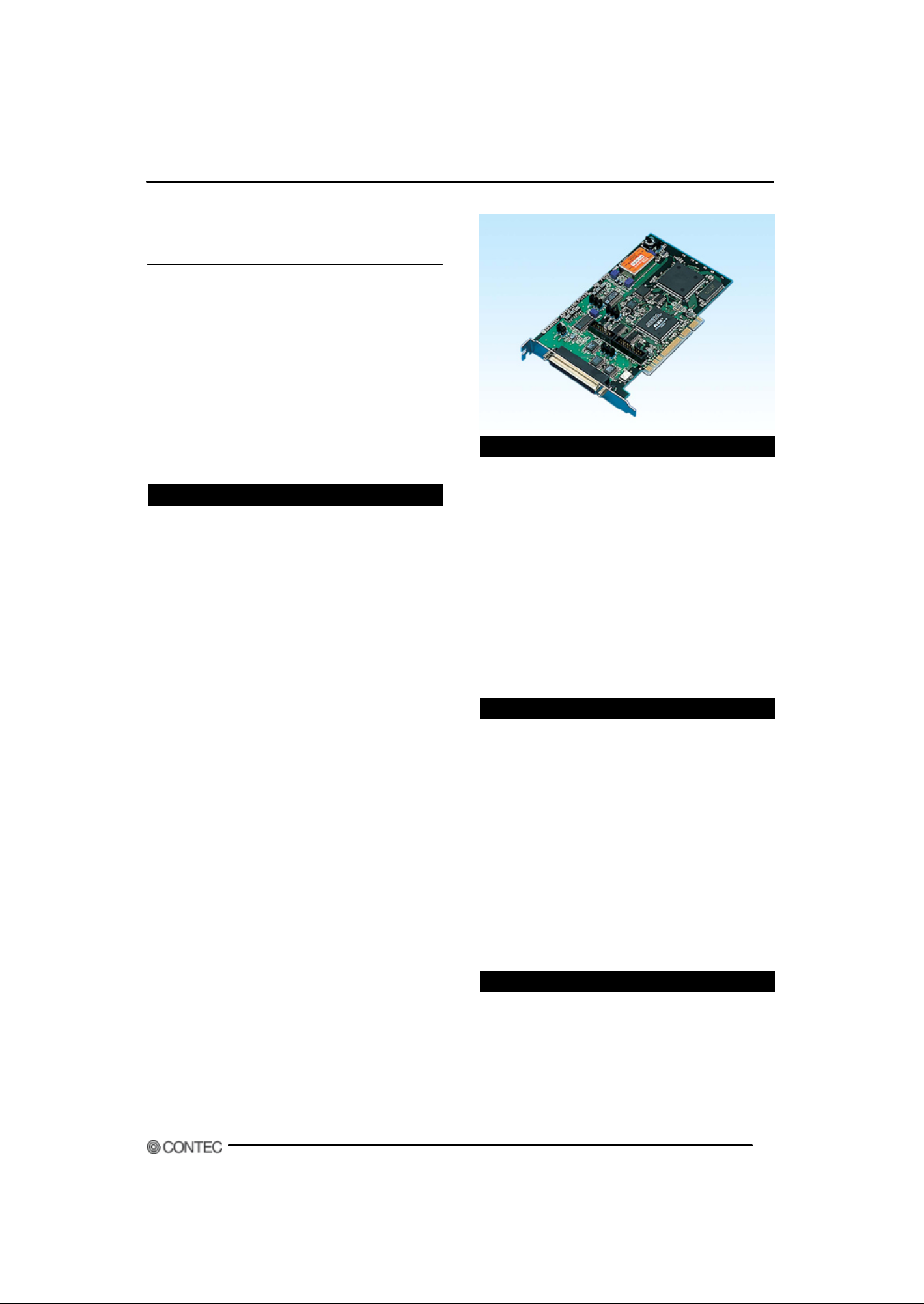
PCI-bus Analog Input Multi-Function Board
AD12-16(PCI )E
T his b oard is int erface board of t he PCI bus conformit y
which input s ana log signal and perform s conversi on (AD
t ranslat ion) t o a digit al signal.
A gene ral-purpose type is Conversion spee d: 10µsec/ ch,
resol ut ion: A/D conversion is performed by 12 bits.
By using at t ached API funct i on library API-PAC(W32 ), t he
applic at ion soft ware for Wi ndows can b e creat ed by t he
various p rogram ming languages which are supporting
Win32A PI funct ions, such as Visual Basic, and Visual C/
C++.
Features
- Single end 16ch, 8ch different ial(Analo g input funct ion)
Selection of a sin gle, and input and dif ferent ial input is
p ossible at t he jumper on board. The t urn of t he channel t o
change can be beforehand set as an exclusive register
arbitrarily . Moreover, ext ension ( a maximum of 32
channe ls) of t he number of input channels and a
simultaneous sampling are r ealiz able by using optional
unit.
- Buffer memory loading(Analo g inp ut fun ct ion)
T he buffer memor y for 256K dat a whic h can be used in
FIFO o r ring form is carrie d on board. T he sampl ing as
backgr ound proces sing independent of t h e t hroughp u t of a
personal computer is p ossible.
- Colorf ul sampling cont rol funct ion(Analo g input funct ion)
A st ar t /st op of a sampling ca n det ect and cont rol t h e siz e
of not only t he command of so ft ware but analog signa l, and
t he s ignal of T T L level. Moreover, select ion of t he internal
sampli ng clock w hich uses t he clock generat or of board
loadin g, and t he ext ernal sa mpling clo ck which uses t he
digital signal input t ed f rom t he outside is possible fo r t he
sampli ng clock whi ch det ermin es sampling sp eed.
- Analog output funct ion
Analo g output f unct ion of one chan nel is car ried.
- Digital I/O function
It has four digit al inp ut s of T T L level, and four digit al
output s, and t he monit or of e xt ernal apparat us and c ont rol
can be performed.
- Abundant Option
Furt h ermore, t h e op t ion apparat us which ext e nds a
function can be used.
By using opt ion apparat u s, a funct ional ris e and
connection can be performed easily.
Pleas e refer t o "cable connect or" a nd "accessories" about an
option.
AD12-16(PCI)EVer.3.10
Accessories (Option)
Accessories (Option)
Termi nal unit f or solderl ess t ermi nal : DT P- 3(PC)
Termina l unit for l eads : DT P-4 (PC)
BNC connector relay terminal unit : ATP -16 *2
Solderless terminal relay terminal s tand : FTP-15 *3
Solderless relay terminal unit : EPD -37 *2
Simul t aneous sa mpling fun ct ional ext ension bo ard :
ATSS-16 *2
Insulated functional extension board : ATII-8A *2
Low path filter extension board : ATLF-8 *2
Channel extens ion board : ATCH-16(PCI)
*2 Option cable of PCB37P S-*P is required (0.5m is
recommended).
*3 Option cable of DT/E2 and PCB15P-1.5 are required.
Cable & Connector (Option)
Cable (Option)
37p in D-SUB 37-pin flat ca ble : PCA3 7P-1.5
37p in D-SUB 37-pi n shield c able :
PCA37P S-*P (0.5m, 1.5m)
37p in D-SUB 37 pin D-SUB shield ca ble :
PCB37P S-*P (0.5m, 1.5m)
15p in D-SUB 15pi n flat cab le : PCA15 P-1.5
15p in D-SUB bot h- ends connector flat c able :
PCB15P-1.5 *1
Coaxia l cable fo r single end input (1 6ch) :
PCC16PS-* (1.5m, 3m)
2pin s hield cable for 16ch (8ch) : PCD8PS-* (1.5m, 3m)
16pin flat cable(1.5m) : DT/E1
15p in D-SUB conversion cable : DT /E2
*1 FT P -15 is required only at t he t ime o f use.
Packing List
- Board [AD12-16(PCI)E] - 1
- User's Guide - 1
- CD-ROM [API-PAC(W32)] - 1
1
Page 2
Ver.3.10AD12-16(PCI)E
Specification
Digital I/O
Counter
Interrupt
Interface Connectors
I/O Address
Warm Up Time
Operation Environment
Analog Input
Number of Channels
Input Range
Absolute Max. Input Voltage ±20V
Input Impedance More than 1M Ohm
Resolution
Conversion Speed
Conversion Accuracy
Non-linearity error (Note 1)
Buffer Memory
Conversion Start Trigger
Conversion Stop Trigger
Analog Output
Number of Channel
Output Range
Output Current Ability
Resolution
Non-Linea rity Error (Note 1) ±1/2LSB
Conversion Speed
Power consumption (Note 2) +5VDC, 1100mA Max.
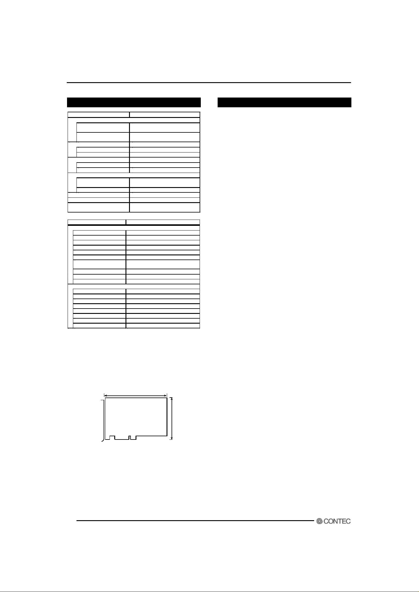
Dimensions (inch)
Note 1:
Note 2:
Board size
Item Specification
Number of Output Channels
Number of Input Channels
Counter Devi ce
Counter Clock
Interrupt Request Level
Interrupt Request Causes Up to 15 causes
CN1
CN2
Item Specification
When the environment temperature is near 0ºC or 50ºC, the
non-linearity error may become larger. A maximum ±0.1% FSR
non-linearity error is possible.
We suppose you to calibrate the board under the work environment
that will give you a better accuracy.
If an external device requires this AD12 -16 (PCI)E board to supply
+5VDC from the CN1 or CN2 connectors, the power consumption of
this board will be bigger than what this specification has defined.
TTL Level 4 channels
(One is shared by counter output)
TTL Level 4 Channels (Two of these are
also used as counter control signals)
i8254 compatible
Internal 4MHz or external signal
One of IRQ resources
D-Type 37 -Pin female connector
#4 -40UNC
16-Pin Pin-header connector
8 bits, 16 ports
15 minutes
Temperature = 0~50°C
Humidity : 20~90% (No-condensing)
16 single-ended channels or 8 differential
Un-isolated ± 10V, or 0~10V
12 bits
10µsec/ch. Max.
±2LSB (Gain= x 1 and x 2)
±4LSB (Gain= x 4 and x 8)
256K Words FIFO or 256K Words Ring
Software command, analog input signal
Software command, storage data number
1 single-ended channel
Un-isolated ±10V, ±5V or 0~10V
±5mA Max.
12 bits
6µsec Max.
6.9 x 4.2 (176.4mm x 107mm)
176.4
[mm]
Support Software
Attached support software
API Function Library API-PAC(W32)
It is the library software which offers the command to the
hardware of our company in standard Win32API function (DLL)
form for Windows.
By the various programming languages which are supporting
Win32API functions, such as Visual Basic, and Visual C/C++,
the high-speed application software which harnessed the special feature of the hardware of our company can be created.
Moreover, it can use also for the check of hardware of operation by the installed diagnostic program.
For details, please refer to Help or the homepage of our company in appending CD-ROM.
Main correspondences OS Windows XP, 2000, NT, Me, 98,
etc.
Main adaptation languages Visual C/C++, Borland C++, Visual
Basic, etc.
Others The hard disk which has 20MB empty domain for every library software is required.
The newest driver and download service (http://www.contec.
co.jp/apipac/) of difference file are also offered.
Optional Support Software
Collection for measurement systems development of ActiveX
components
ACX-PAC(W32)BP
It is convenient measurement systems development tool for
Windows in which collection of examples which can be used
immediately, and collection (collection of software parts) of
components which can program easily only by combining were
mentioned.
Component for control of the input-and-output board (card) of
our company is made the one package. Analog I/O, digital I/O,
control of each interface of GPIB communication and X-Y graph
display, and file preservation are possible.
Collection for measurement systems development of ActiveX
components
ACX-PAC(W32)AP
It is convenient measurement systems development tool for
Windows in which collection of examples which can be used
immediately, and collection (collection of software parts) of
components which can program easily only by combining were
mentioned.
In addition to the function of ACX-PAC(W32)BP, components,
such as display systems, such as various graph, switch, and
107.0
lamp, and operation / analysis, serve as a package.
DDE server DDE SERVER(W32)
It is the software which transmits to DDE client by the cycle
which specified the data from the hardware of our company, or
setup. Data collection / analysis system can be easily created
combining DDE client software, such as Excel97, and
Wonderware InTouch, Visual Basic.
MS-DOS correspondence driver SUPPORT-PAC(PC)306
It is a driver dealing with MS-DOS which supports the hardware of our company. Much high-class language is supported
and the function to provide is supplied per command (function).
2
Page 3
AD12-16(PCI)EVer.3.10
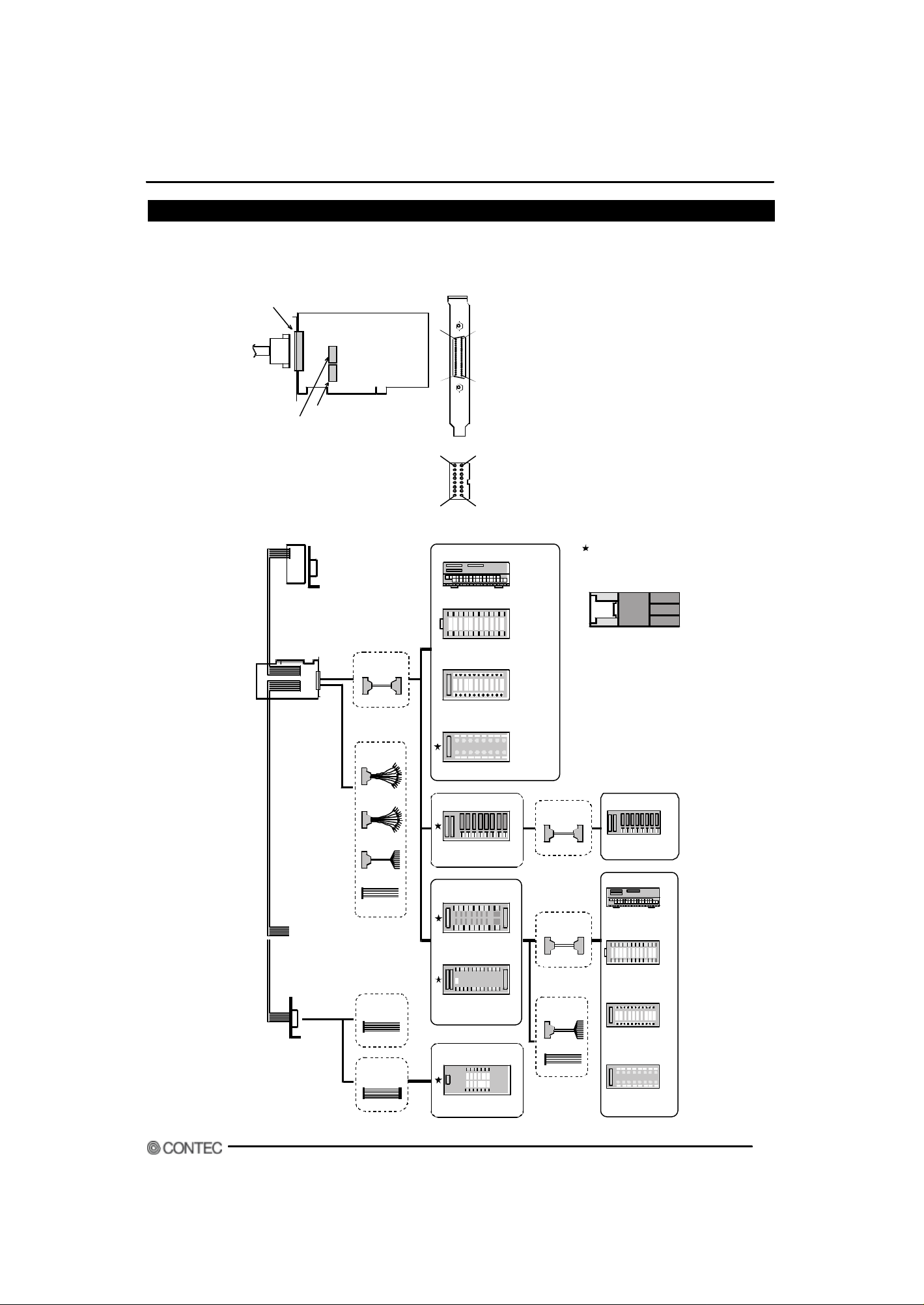
External Connection
Connection method with a connector
Connec t ion bet we en t his board and ext ernal apparat us is made by t h e int erfac e connect or on board (CN1 and CN2).
Int erf ace connec t or has two, t he obje ct for ana log I/O (C N1: D-SUB 3 7p in Femal e), and t h e object fo r cont rol signals, s uch as
digital I/O and counter control, (CN2: 16pin Pin-header).
I nter face connector(CN1)
Interface connector (CN 3)
Interface connector (CN 2)
It is the connector (CN 3) f or ATUH -16(PCI )
Examples of Connecting Options
1 6CH Multiplexer Sub-Board
ATU H-16 (PCI )
* A n external power supply is
required to use a combination of
channel expansion and extension
boar ds.
Analog E Series
Option
Cable
PCB37PS * 1
37
20
19
- Connector used
A 37pin D type connector [F (female)type]
DCLC-J37SAF-20L9 [mfd.by JAE ] equivalent
1
- Applicable connector
17JE-23370-02(D8C) [mfd by DDK, M(male)type]
CN 1
A8B8
- Applicable connector
PS-16SEN-D4P1-1C [mfd.by JAE]
CN2
A1B1
Rel ay t er min a l st a nd
Ter minal unit
EPD-37
For Solder Terminal
D TP-3(PC)
* 1 -m shielded cable bundled
For leads
D TP-4(PC)
* 1 -m shielded cable bundled
The accessory with this
mark ca n be mounted on
a DI N ra il by u sin g
DIN -ADP 1.
* 1 : PCB 37PS-0.5 P is
recommended .
Digital I/O Cable
DT/E1
Digital I/O
Cable
DT/E2
Opt ion
Cabl e
PCC16PS
PCD8PS
PCA37PS
PCA37P
Option
Cable
PCA15P
Option
Cable
PCB15P
For BNC connector
ATP-16
Extended functional
board
Isolated functional
extension
ATII-8A
Extended functional
boar d
1 6 Ch a nnel
Simultaneous Sample
A TSS-16
Low path filter
extension board
ATL F-8
Relay terminal stand
Multi-function board
FTP-15
Option
Cable
PCB37PS *1
Opti on
Cabl e
PCB37PS *1
Opti on
Cable
PCA37PS
PCA37P
Extended functional
boar d
Isolated functional
extension
ATII-8A
Relay terminal sta nd
Terminal unit
EPD-37
For Solder Terminal
DTP-3(PC)
* 1-m shielded
cable bundled
For leads
DTP-4(PC)
* 1 -m shielded
cable bundled
For BNC connect or
ATP-16
3
Page 4

Connector Pin Assignment
Digital ground common to "Simultaneous Hold Output" and "+5V DC from
< Single-Ended Input > < Differential Input >
D igi t al Gr ou n d
Analog Ground
Analog Ground
Analog Ground
Analog Ground
Analog Ground
Analog Ground
Analog Ground
Analog Ground
Analog Ground
Analog Ground
Analog Ground
Analog Ground
Analog Ground
Analog Ground
Analog Ground
Analog Ground
Analog Ground
CN1
19
+5V DC fr om PC
37
18
Simultaneous Hold Output
36
17
Anal og Ou t p u t
35
16
Anal og I n p u t 15
34
15
Anal og I n p u t 7
33
14
Anal og I n p u t 14
32
13
Anal og I n p u t 6
31
12
Anal og I n p u t 13
30
11
Anal og I n p u t 5
29
10
Anal og I n p u t 12
28
9
Anal og I n p u t 4
27
8
Anal og I n p u t 11
26
7
Anal og I n p u t 3
25
6
Anal og I n p u t 10
24
5
Anal og I n p u t 2
23
4
Anal og I n p u t 9
22
3
Anal og I n p u t 1
21
2
Anal og I n p u t 8
20
1
Anal og I n p u t 0
Di git al Grou n d
Analog Gr ound
Analog Gr ound
Analog Gr ound
Analog Gr ound
Analog Gr ound
Analog Gr ound
Analog Gr ound
Analog Gr ound
Analog Gr ound
Analog Gr ound
Analog Gr ound
Analog Gr ound
Analog Gr ound
Analog Gr ound
Analog Gr ound
Analog Gr ound
Analog Gr ound
CN 1
19
+5V DC from PC
37
18
Simul t an eou s Hol d Ou t p ut
36
17
Analog Output
35
16
Analog Input 7 [-]
34
15
Analog Input 7 [+]
33
14
Analog Input 6 [-]
32
13
Analog Input 6 [+]
31
12
Analog Input 5 [-]
30
11
Analog Input 5 [+]
29
10
Analog Input 4 [-]
28
9
Analog Input 4 [+]
27
8
Analog Input 3 [-]
26
7
Analog Input 3 [+]
25
6
Analog Input 2 [-]
24
5
Analog Input 2 [+]
23
4
Analog Input 1 [-]
22
3
Analog Input 1 [+]
21
2
Analog Input 0 [-]
20
1
Analog Input 0 [+]
Ver.3.10AD12-16(PCI)E
Analog Input 0
to Analog Input 15
Analog Input 0[+]
to Analog Input 15[+]
Analog Input 0[-]
to Analog Input 15[-]
Analog input signals in single-ended input mode.
The numbers correspond to channel numbers.
Analog input signals in differential input mode.
The numbers correspond to channel numbers.
Analog input signals in differential input mode.
The numbers correspond to channel numbers.
Analog Output Analog output signal
Analog Ground Analog ground common to analog I/O signals.
Simultaneous Hold
Output
Control signal for simultaneous sampling unit ATSS-16 available as an
option.
+5V DC from PC Supplies 3 amperes of current at +5 volts.
Digital Ground
PC".
Notes!
- Please connect each output and power s upply output neither with analog ground nor digital ground too hastily.
- Moreover, please do not connect output and output. It becomes the cause of failure.
CN2
A8
B8
N . C.
Exter nal Sampling Clock Input
External St ar t Trigger Input
Digital I nput 2 / CN T Cl ock
D igi t al Ou t p u t 3 / CN T Ou t p u t
Digital Input 0 Digital input signal.
Digital Input 1
/CNT Gate
Digital Input 2
/CNT Clock
Digital Input 3
/INT Trigger
Digital Out 0
to Digital Out 2
Digital Out 3
to CNT Output
External Start Trigger Input External trigger input signal for sampling start conditions
External Stop Trigger Input External trigger input signal for sampling stop conditions
External Sampling Clock
Input
Sampling Clock Output Sampling clock output signal
+5V DC from PC Supplies 1 ampere of current at +5 volts.
Digital Ground Digital ground common to the signals and “+5V DC from PC”.
N.C. No connection to this pin.
Di gi t al Gr oun d
Digital Input 0
Digital Output 1
Digital input signal.
Also serving as the counter gate control input signal.
Digital input signal.
Also serving as the clock input signal
Digital input signal.
Also serving as the interrupt input signal.
Digital output signal.
Digital output signal.
Capable of being jumper-switched to serve as the counter output
signal.
External sampling clock input signal
B7
B6
B5
B4
B3
B2
B1
+5V D C fr om P C
A7
Sampl in g Clock Ou t pu t
A6
Exter nal Stop Trigger I nput
A5
Di gi t al I n p u t 3 / I N T Tr ig ger
A4
Di gi t al I n p u t 1 / CNT Ga t e
A3
Di gi t al Gr ou n d
A2
Di gi t al Ou t p u t 2
A1
Di gi t al Ou t p u t 0
Notes!
- Please connect each output and power s upply output neither with analog ground nor digital ground too hastily.
- Moreover, please do not connect output and output. It becomes the cause of failure.
4
Page 5

AD12-16(PCI)EVer.3.10
Analog Input Connection
T he input form o f analog si gnal has a single and input , and different ial input , and t he co nnect ion met hods wit h a signal differ,
respect ively . He re, t he example in t h e case of connect ing using a f lat cable o r a shield cable is shown.
Single-ended Input
It is examp le of connect io n when usin g cables, such as opt ional flat cable (PC A37P).
T he source of a signal and a ground a re connect ed t o 1 t o 1 t o each a nalog input channel o f CN1.
BOARD CN 1 Cab le Signal Source
Analog Input 0 ..1 5
Analog Ground
It is t he exampl e of connect ion which used shiel d cables, such as an opt ional c oaxial cabl e (PCC16PS). When t he dist ance of t he
source of a sign al and a b oard is long, please use it t o enlarge noise-p roof nat ure. T o each analo g input channel of C N1, wire l ine is
connected to signal line and the group edited by the shield is connected to a ground.
BOARD CN1 Signal Source
Analog Input 0 ..1 5
Analog Ground
Notes!
- When a frequency ingredient 1MHz or more is contained in the source of signal, the cross talk between channels may occur.
- When a board and the source of a signal are influenced of a noise, or when the distance of a board and the source of a signal is
long, it may be unable to input in exact data by the connection method.
- Analog signal to input must not exceed the maxim um input voltage on the basis of the analog ground of a board. It may
damage, when it exceeds.
- Conver sion data is unknown when input terminal is not connected. Please connect with analog ground too hastily the input
terminal of a channel which is not connected to the sour ce of a signal.
Shield cable
Differential Input
It is example of connectio n when usin g cables, such as opt ional flat cable (PC A37P).
[+] input of each analog input channel of CN1 is connect ed t o a signal, and [-] input is connect ed t o t he ground o f t he sourc e of a
signal. Furthermore, the analog ground of a board and the ground of the source of a signal are connected.
BOARD
Analog Input 0[ +] ..7 [+]
Analog Input 0[ -]. .7[ -]
Analog Ground
CN 1
It is t he examp le of connec t ion which used shield cables, su ch as optional 2 hear t shield ca ble (PCD8PS). When t h e dist ance of t he
source of a signal and a b oard is long, please use it t o enlarge no ise-p roof nat ure. [+ ] input of each anal og input c hannel of CN1 is
connected t o a s ignal, and [-] input is connec t ed t o t he ground of t he sourc e of a signal. Furt h ermore, t h e analog ground of a board
and the ground of the source of a signal are connected in the group edited by the s hield.
BOARD
Analog Input 0[ +] ..7 [+]
Analog Input 0[ -]. .7[ -]
Analog Ground
CN 1 Shield cable
Notes!
- When a frequency ingredient 1MHz or more is contained in the source of signal, the cross talk between channels may occur.
- Conver sion data becomes unfixed when analog ground is not connected.
- When a board and the sour ce of a signal are influenced of a noise, or when the distance of a board and the source of a
signal is long, it may be unable to input in exact data by the connection method.
- Analog signal inputted into [+] input and [-] input must not exceed the maximum input voltage on the basis of the analog
ground of a board. It may damage, when it exceeds.
- Conver sion data when having not connected terminal of [+] input or [-] input is unfixed. Both should connect with an analog
ground too hastily the term inal of [+] input of the channel which does not connect with the source of a signal, and [-] input.
Cable Signal Source
Signal Source
5
Page 6

Ver.3.10AD12-16(PCI)E
Analog Output Connection
T he example in t h e case of connect ing an analog o utput signal using a flat cable or a shiel d cable is shown.
It is example of connection when usin g cables, such as opt ional flat cable (PC A37P).
T he an alog out put and anal og ground of CN1 are connect ed t o t he input and ground of external apparat us.
BOARD CN 1 Cabl e Target
Analog Output
Analog Ground
It is t he exampl e of connect ion which used t he s hield cable . Please use it t o enlarge t he case where t he dist anc e of a boa rd and
ext ernal apparat us is long, and noise- proof nature. T o t he analog output of CN1, wire line is connected t o a signal line a nd t he
group edited by the shield is connected to a ground.
BOARD CN 1
Analog Output
Analog Ground
Shield cable
Notes!
- When a board and a target are influenced of noise, or when the dis tance of a board and a target is long, exact data may be
unable to be outputted depending on the connection m ethod.
- The ma ximum outp ut current capacity o f analog ou tput signa l is +/-5mA . Please co nnect with a board af ter check i ng the
specification for connection.
- Please connect analog output signal neither with analog gr ound nor digital ground too hastily. It becomes the cause of failure.
Target
Digital I/O Connection
T he example in t he case of connect in g a digit a l I/O sign al and cont rol signa ls (ext ern al t rigger input signal, sampl ing clock out put
signal , et c.) using a flat cable is shown.
CN2 an d external apparat us are connec t ed using opt ional fl at cable ( DT /E1), 15p in D-SUB connect or ( DT /E2) wit h a bracket , et c.
All of t hese digit al I/O s ignals and a control signal are t he signa ls of T T L level.
Digital Input Connection
CN2 Cable Target
BOARD
Digital Output Connection
BOARD
Note!
- Please connect each output neither with analog gr ound nor a digital ground too hastily. It becomes the cause of failure.
10k Ohm
Digital Ground
Output
I OL=24mA
Digital Ground
Input
CN2 Cable Target
6
Page 7

Block Diagram
AD12-16(PCI)EVer.3.10
16 single-ended /
8 differentia l
A nalog Inputs
8/16 channel
multiplexer
with over voltage
pr otection
Instrument
amplifier
Sample & Hold
amplifier
A/D
converter
DC/D C
converter
Analog Outputs Counter
CN 1 CN2
D/A
convert er
Simultaneous
Hold
On board
memory
PCI Bus
ASIC
4 Digital Input /
4 Digital Output /
control signals
1 6-bi t counter 2
1 6-bi t counter 1
1 6-bi t counter 0
PCI Bus interface
signals
Counter 8254
All data subject to change without notice.
7
 Loading...