

Page 1
V7 / V15 / V15a
Hearing Loop Drivers
Installation &
User Guide
November 2019
1
Page 2

Contents
Product Overview
Components
Connections
Suitable Cable Lengths
Start-Up Tests
Controls
Hearing Loop Setup
Troubleshooting
Technical Specications
Standards
3
4-5
6-7
8-10
12
13-21
22-27
28
29-31
32
Contacta has a policy of continuous product development, therefore small specication changes
may not be reected in this manual. Images, labels, packaging, accessories and product colours
are subject to change without notice.
2
Page 3

Product Overview
Our highly eicient and compact V7, V15 and V15a hearing loop drivers
are suitable for smaller facilities and venues.
The V7 and V15 are constant current hearing loop drivers which power
hearing loops utilising a single output. The V15a is a constant current
dual output hearing loop driver with integral phase shifter for phased
array conguration.
These hearing loop drivers have Class-D amplier output stages and
an audio subsystem built around an advanced DSP core. Combined
with a powerful CPU that ensures peak performance, they use cutting
edge technology proven in the pro audio world to achieve life-like
speech and rst-class music reproduction.
Note: For large area hearing loop installation instructions, consult the
Large Area Hearing Loop Installation Guide.
3
Page 4
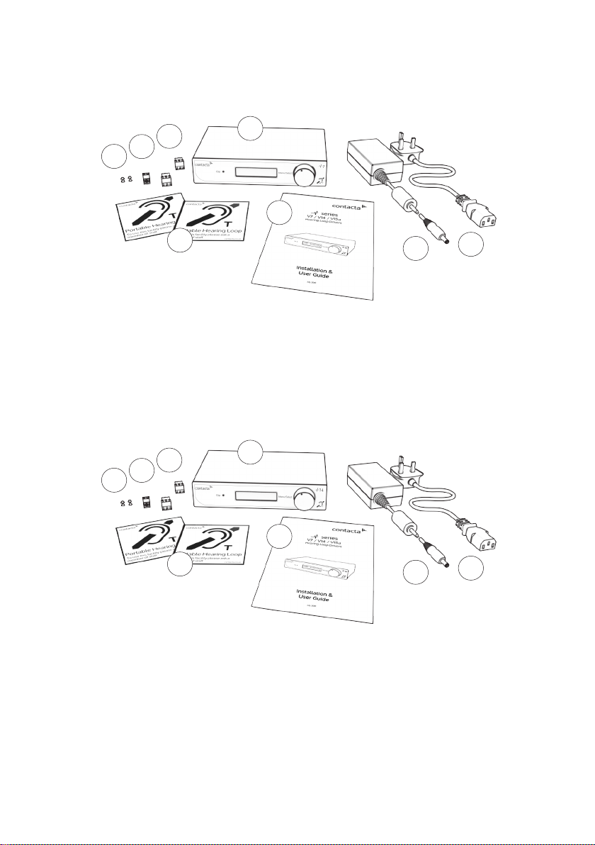
V7
Components
3
2
1
5
6
4
1. Rubber Feet x4
2. 5.08mm Euro-Block Connector
3. 3.81mm Euro-Block Connector x2
4. Signage
V15
3
2
1
4
1. Rubber Feet x4
2. 5.08mm Euro-Block Connector
3. 3.81mm Euro-Block Connector x2
4. Signage
5
6
7
5. V7 Hearing Loop Driver
6. Installation & User Guide
7. Power Supply [PS-55]
8. IEC Power Lead
7
5. V15 Hearing Loop Driver
6. Installation & User Guide
7. Power Supply [PS-60]
8. IEC Power Lead
8
*
8
*
*
Plug type varies by country.
4
Page 5
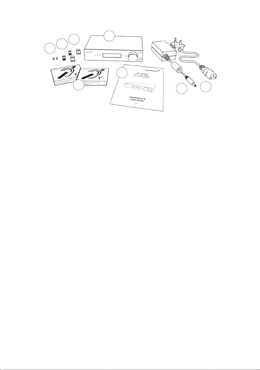
V15a
3
2
1
5
6
4
1. Rubber Feet x4
2. 5.08mm Euro-Block Connector x2
3. 3.81mm Euro-Block Connector x2
4. Signage
7
8
5. V15a Hearing Loop Driver
6. Installation & User Guide
7. Power Supply [PS-60]
8. IEC Power Lead
*
*
Plug type varies by country.
Cable & Equipment: A length of loop cable determined by the loop
design is also required. Hearing loop drivers also require ancillary
equipment for audio feeds, such as a microphone or sound system.
5
Page 6
Connections
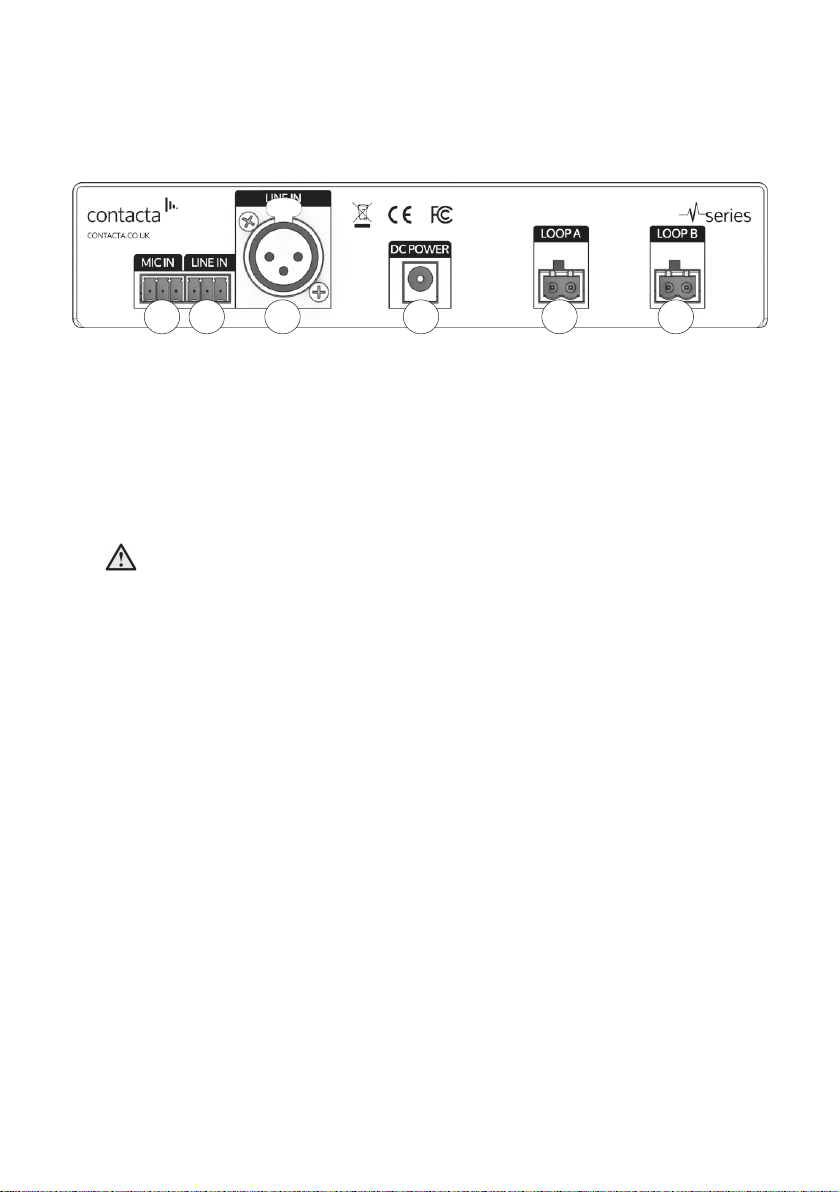
Rear Panel Connections
1 2
1. Microphone Input - 3.81mm Euro-block balanced microphone
input (12V phantom power via 680Ω).
2. Line Input 1* - 3.81mm Euro-block balanced line input/feedthrough.
3. Line Input 2* - XLR balanced line input/feedthrough.
4. Power Supply Input - *V7 DC Power Input, 2.1mm 14Vdc 2.14A
***V15 DC Power Input, 2.1mm 24Vdc 4.17A
**V15a DC Power Input, 2.1mm 24Vdc 4.17A
Caution: Use only the provided Power Supply.
5. Loop A Output - 5.08mm Euro-block.
6. Loop B Output - 5.08mm Euro-block [V15a only].
*
Note: Only connect to one Line Input at a time.
3
4
5
6
6
Page 7
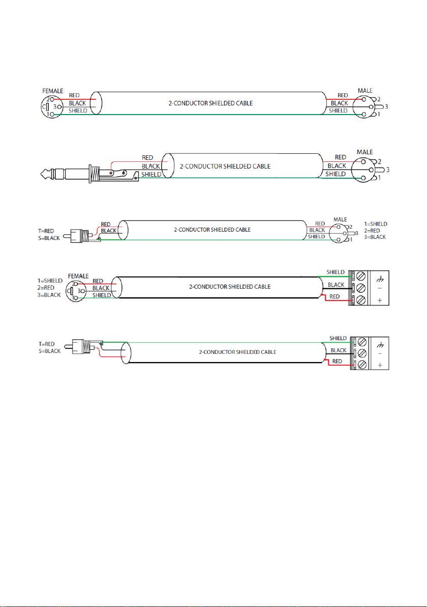
Connection Examples
XLR to XLR (line)
TRS to XLR (line)
Unbalanced to XLR
XLR to Euroblock (balanced)
Unbalanced to Euroblock
7
Page 8
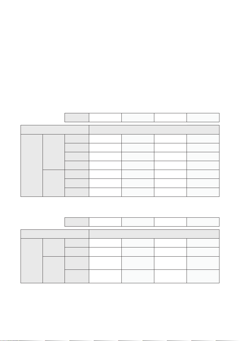
Suitable Cable Lengths
The tables in this section show the approximate maximum cable
lengths for diering maximum required currents.
Loop impedance (at 1.6kHz) should be less than the voltage capability
of the driver (V7: 7.5Vrms, V15: 15Vrms, V15a: 15Vrms) divided by the
required current.
This achieves 400mA/m eld strength at 1kHz.
V7 Single-Turn Hearing Loop (Metric)
Current 2.0A 3.0A 4.0A 5.0A
Cable Type Cable Length
Maximum
Cable
Length
Round
Cable
(CSA)
Flat Cable
(Width)
0.5mm 85m 56m 42m 34m
1mm 133m 89m 66m 53m
1.5mm 155m 103m 77m 62m
2.5mm 173m 115m 86m 69m
10mm 101m 67m 50m 40m
12.5mm 192m 128m 96m 77m
25mm 255m 170m 127m 102m
V7 Single-Turn Hearing Loop (Imperial)
Current 2.0A 3.0A 4.0A 5.0A
Cable Type Cable Length
Maximum
Cable
Length
Round
Cable
(AWG)
Flat Cable
(Width)
18AWG 438ft 292ft 219ft 175ft
14AWG 593ft 395ft 296ft 237ft
18AWG
(equivalent)
14AWG
(equivalent)
505ft 336ft 252ft 202ft
711ft 474ft 355ft 284ft
8
Page 9
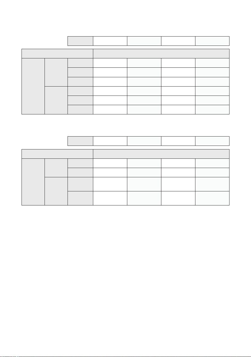
V15 Single-Turn Hearing Loop (Metric)
Current 2.0A 3.0A 4.0A 5.0A
Cable Type Cable Length
Maximum
Cable
Length
Round
Cable
(CSA)
Flat Cable
(Width)
1mm 242m 161m 121m 97m
1.5mm 284m 189m 142m 114m
2.5mm 319m 213m 160m 128m
10mm 180m 120m 90m 72m
12.5mm 340m 226m 170m 136m
25mm 450m 300m 225m 180m
V15 Single-Turn Hearing Loop (Imperial)
Current 2.0A 3.0A 4.0A 5.0A
Cable Type Cable Length
Maximum
Cable
Length
Round
Cable
(AWG)
Flat Cable
(Width)
18AWG 746ft 498ft 373ft 299ft
14AWG 997ft 664ft 498ft 399ft
18AWG
(equivalent)
14AWG
(equivalent)
840ft 560ft 420ft 336ft
1327ft 885ft 663ft 531ft
9
Page 10
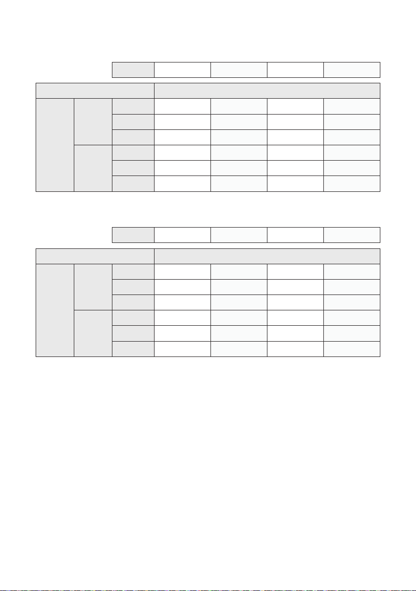
V15a Single-Turn Hearing Loop (Metric)
Current 2.0A 3.0A 4.0A 5.0A
Cable Type Cable Length
Maximum
Cable
Length
Round
Cable
(CSA)
Flat Cable
(Width)
1mm 266m 177m 133m 106m
1.5mm 311m 208m 156m 125m
2.5mm 350m 233m 175m 140m
10mm 197m 131m 99m 79m
12.5mm 373m 249m 186m 149m
25mm 493m 329m 247m 197m
V15a Double-Turn Hearing Loop (Metric)
Current 2.0A 3.0A 4.0A 5.0A
Cable Type Cable Length
Maximum
Cable
Length
Round
Cable
(CSA)
Flat Cable
(Width)
1mm 193m 129m 97m 77m
1.5mm 209m 139m 104m 83m
2.5mm 219m 146m 110m 88m
10mm 172m 115m 86m 69m
12.5mm 267m 178m 133m 107m
25mm 316m 211m 158m 126m
10
Page 11
V15a Single-Turn Hearing Loop (Imperial)
Current 2.0A 3.0A 4.0A 5.0A
Cable Type Cable Length
Maximum
Cable
Length
Round
Cable
(AWG)
Flat Cable
(Width)
18AWG 819ft 546ft 409ft 328ft
14AWG 1093ft 729ft 547ft 437ft
18AWG
(equivalent)
14AWG
(equivalent)
921ft 614ft 461ft 369ft
1456ft 971ft 728ft 582ft
V15a Double-Turn Hearing Loop (Imperial)
Current 2.0A 3.0A 4.0A 5.0A
Cable Type Cable Length
Maximum
Cable
Length
Round
Cable
(AWG)
Flat Cable
(Width)
18AWG 598ft 399ft 299ft 239ft
14AWG 684ft 456ft 342ft 273ft
18AWG
(equivalent)
14AWG
(equivalent)
723ft 482ft 362ft 289ft
949ft 633ft 475ft 380ft
11
Page 12
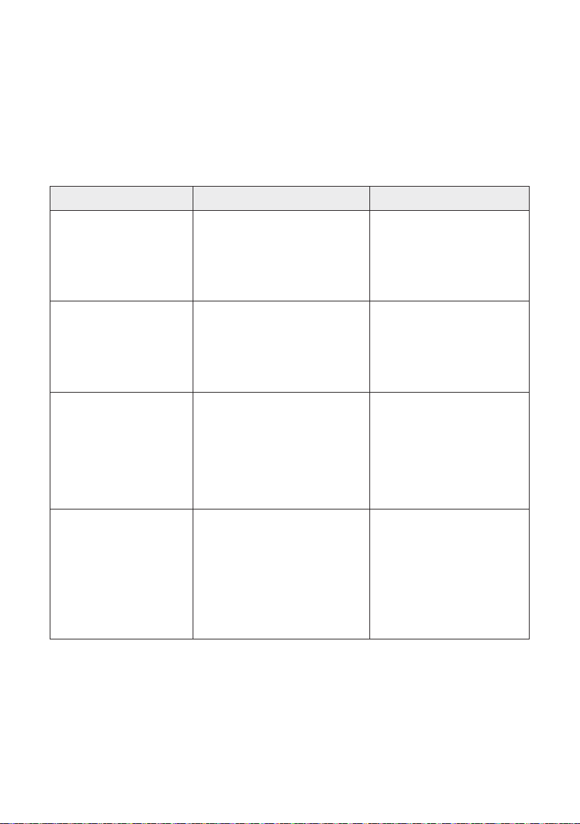
Start-Up Tests
V Series drivers perform a series of tests when powered on, causing a
number of indications to appear on the display screen during start-up.
The meanings of these indications are as follows:
Indicator Meaning Remedy
V7 and V15:
Loop Good
V15a:
Loop A Good
Loop B Good
V7 and V15:
Loop Open Fault
V15a:
Loop A Open Fault
Loop B Open Fault
V7 and V15:
Loop Ground Fault
V15a:
Loop A Ground Fault
Loop B Ground Fault
Incorrect Power The power input supply voltage
Hearing loop(s) is/are correctly
connected to the driver.
Hearing loop(s) is/are improperly
connected to the driver.
An open-circuit loop will not
damage the driver, and start-up
will continue to the main menu.
A ground fault with the hearing
loop(s) has been found.
The driver will halt operation
with this message displayed on
screen, as such a fault would
cause stress to the driver were
normal operation to continue.
from the mains power supply is
incorrect.
The driver will halt operation
with this message displayed on
screen, as such a fault would
cause stress to the driver were it
to continue to normal operation.
None required.
Ensure that the loop(s) is
properly connected to the
driver. The loop current
indication in normal
operation may be used to
conrm the connections.
Switch o the driver and
carefully check the loop(s) for
shorts to ground. Rectify the
faults and re-apply power to
the driver.
Switch o the driver and
connect the power supply
which was provided with the
driver. If this is not available,
contact your distributor to
order a new power supply.
Please note if using V15a: If connecting only one loop to a V15a, whichever loop connection has
not been used (either Loop A or Loop B) will show as an “Open Fault” as default. This is the correct display for operation with only one loop; continue as normal.
12
Page 13
Controls
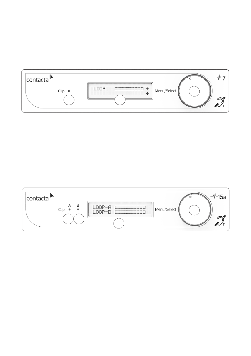
Front Panel Overview
V7 and V15
3
1
1. Clip Status Light - When lit, this status LED indicates the signal on
the hearing loop output is clipping (see Troubleshooting on page
28 for appropriate solutions).
2. Display Screen - Indicates the status of the Loop Output, displays
menu and adjustment options.
3. Control Dial - Used for unlocking and making adjustments.
V15a
2
4
1 2
1. Clip Status Light - When lit, this status LED indicates the signal on
Hearing Loop A is clipping (see Troubleshooting on page 28 for
appropriate solutions).
2. Clip Status Light - When lit, this status LED indicates the signal on
Hearing Loop B is clipping (see Troubleshooting on page 28 for
appropriate solutions).
3. Display Screen - Indicates the status of the Loop Output, displays
menu and adjustment options.
4. Control Dial - Used for unlocking and making adjustments.
3
13
Page 14
Locking/Unlocking the Hearing Loop Driver
The hearing loop driver will power up in Output Current Display Mode
and will be locked from entering Adjustment Mode.
Unlock the Driver
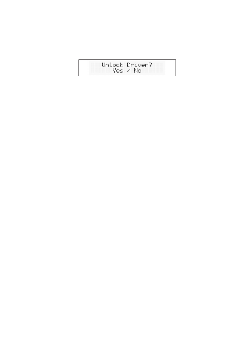
1. To unlock the hearing loop driver, press the control dial, and when
prompted “Unlock driver?” click “Yes.”
2. Enter the passcode 2239:
a. Rotate the control clockwise to select the rst required digit.
b. Press the control dial in to select the digit.
c. Repeat steps (a) and (b) until all the digits have been selected.
Note: Entering the wrong code returns the hearing loop driver to the
lock screen.
Additional Functions and Codes
1. To access one of the additional functions available, press the
control dial, and when prompted “Unlock driver?” click “Yes.”
2. Enter one of the following passcodes:
• 1010: Disable the display backlight 10 minute auto switch-o.
This setting is remembered through power cycles.
• 1011: Enable the display backlight 10 minute auto switch-o.
This setting is remembered through power cycles.
• 9999: Disable the auto re-lock (timeout). This is not
remembered through power cycles.
• 8888: Restore all factory defaults and restart the driver.
14
Page 15
Modes
Main Menu
After being unlocked, the hearing loop driver will display the main
menu. This is indicated by up and down arrows on the display screen.
When in this mode, rotating the hearing loop driver’s control dial
clockwise will move the screen to the next menu item and rotating the
dial anti-clockwise will move it to the previous menu item.
The menu options are as follows:
V7 and V15
1. Loop Output
2. Line Input
3. Phantom Power
4. Microphone Input
5. Current Output (no adjustment)
6. High-Frequency Compensation
Adjustment Mode
Press the control dial in to enter Adjustment Mode; the arrows on the
display screen will move to a left and right position.
Rotate the dial clockwise or anti-clockwise to make the adjustment.
Press the control dial in to conrm the selection and return to the main
menu.
If the control dial is not used for 120 seconds when in Adjustment
Mode the hearing loop driver will revert to the main menu, with Loop
Output as the default screen.
V15a
1. Loop Output
2. Line Input
3. Phantom Power
4. Microphone Input
5. Loop B Trim Adjustment
6. High-Frequency Compensation
15
Page 16
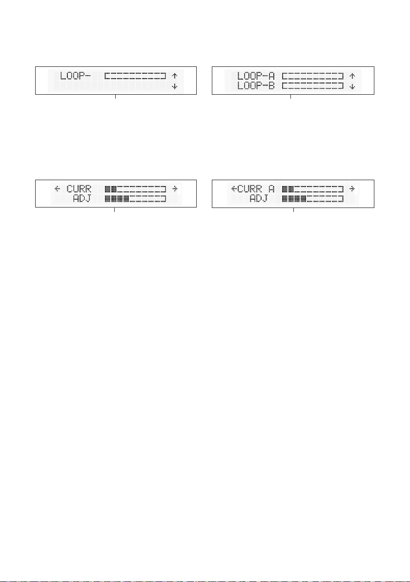
Loop Output
V7 and V15 Loop Output V15a Loop Output
The hearing loop driver’s Loop Output section displays the real-time
output current in 0.5A steps.
Adjustments
V7 and V15 Loop Output: Adjustment Mode V15a Loop Output: Adjustment Mode
In Adjustment Mode, the real-time output current is displayed on the
top line in 0.5A steps. The bottom line indicates the strength of the
loop output level adjustment.
To alter the loop output level, enter Adjustment Mode:
• To increase the loop output level, rotate the control dial clockwise.
• To decrease the loop output level, rotate the control dial
anti-clockwise.
• Press the control dial once to conrm the selection and return to
the main menu.
16
Page 17
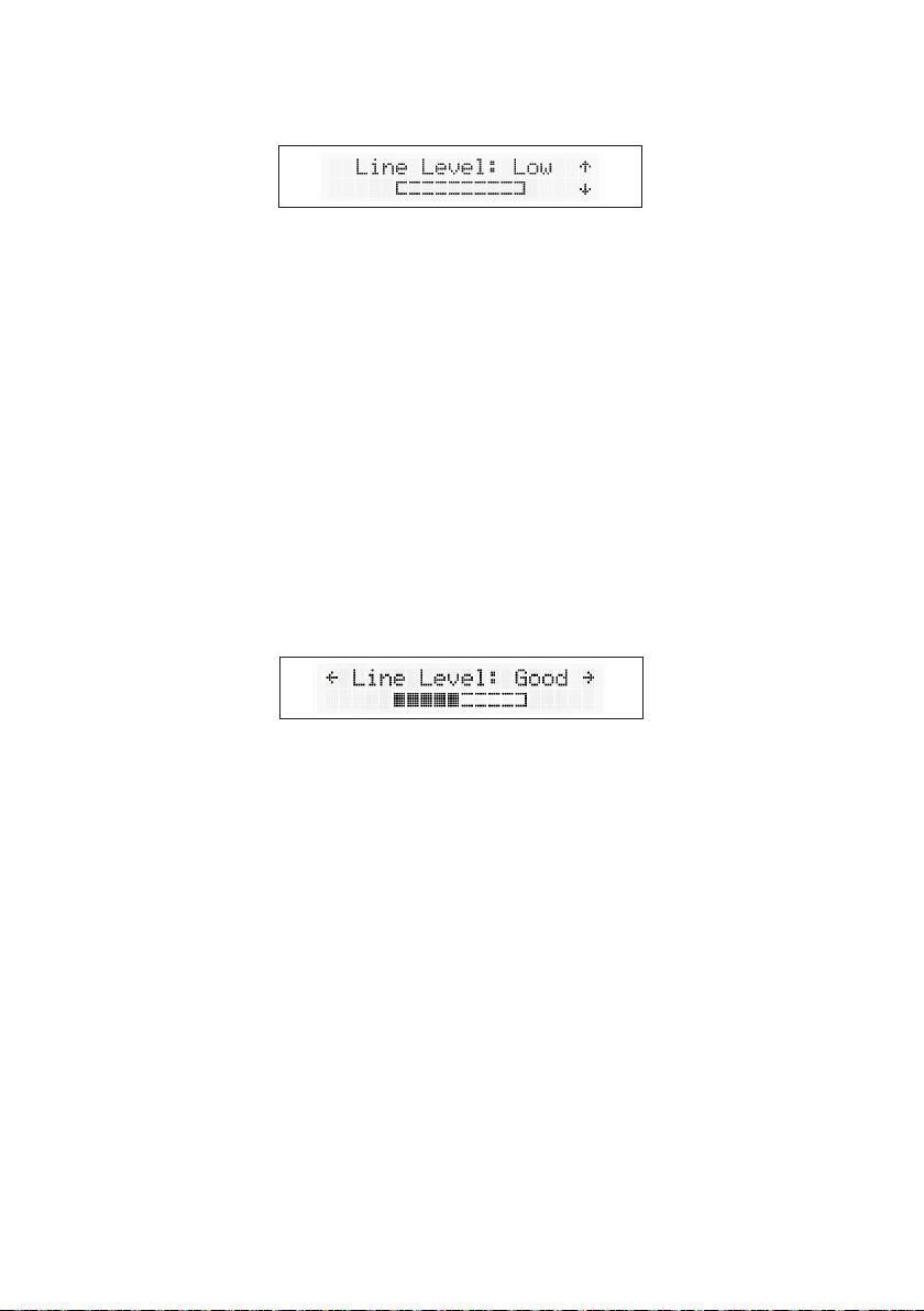
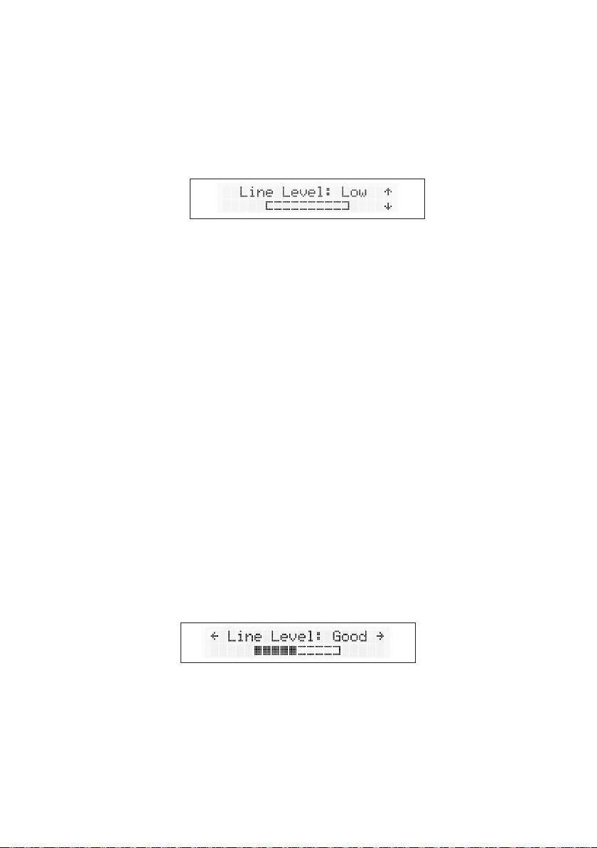
Line Input
The hearing loop driver’s Line Input section displays the line input
level within a range of 47dB.
The text on the display indicates if the correct line level has been
achieved:
• “Low” indicates the line level is too low for the automatic gain
control to operate.
• “Good” indicates the line level is at an optimum level for the
automatic gain control to operate.
• “High” indicates the line level is too high and signal clipping may
occur. Signal clipping will also be shown by the LED.
Adjustments
It is recommended that at least 5 blocks in the adjustment block are
lled (see the above image for an example).
Enter Adjustment Mode, and alter the line input level displayed on the
bar until the text displays ‘Good’:
• To increase the line input level, rotate the control dial clockwise.
• To decrease the line input level, rotate the control dial
anti-clockwise.
• Press the control dial once to conrm the selection and return to
the main menu.
17
Page 18
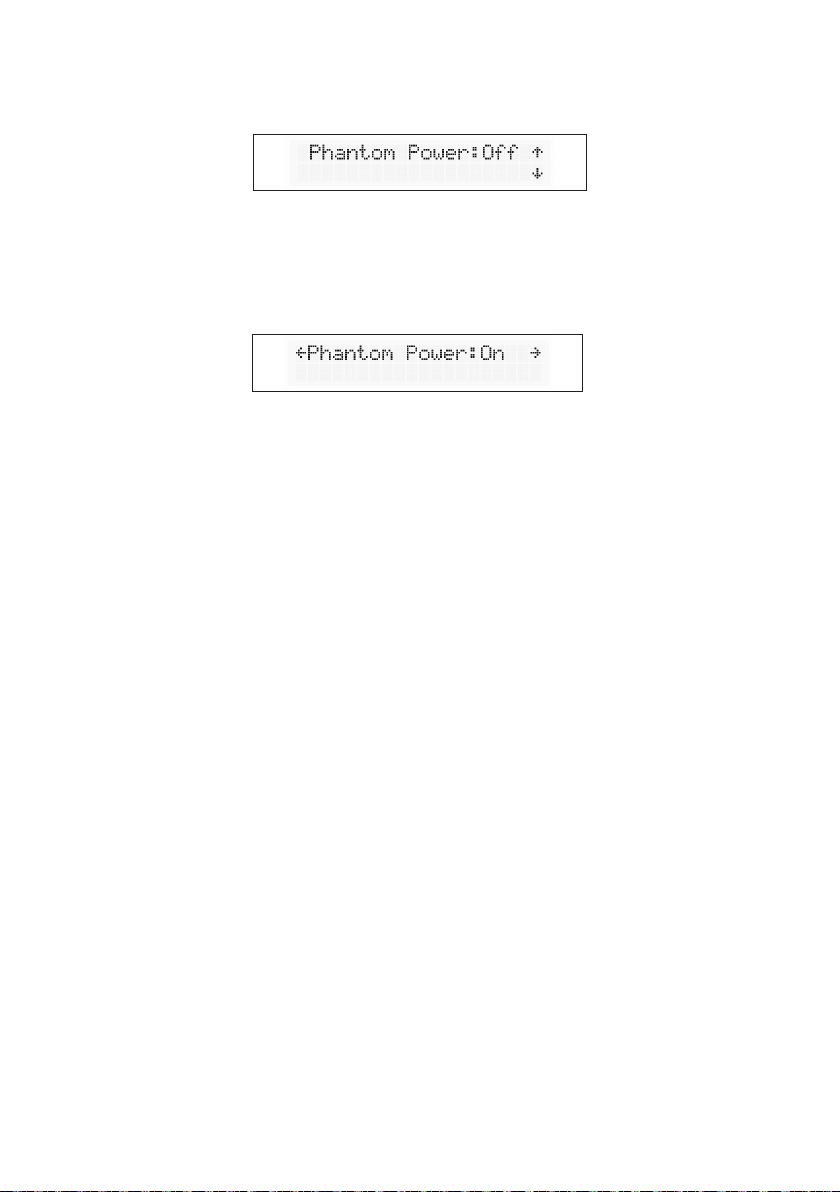
Phantom Power
Phantom power for a connected microphone is set o as the default
setting.
Adjustments
Rotating the control dial clockwise or anti-clockwise in Adjustment
Mode will toggle the phantom power on or o. Press the control dial
once to conrm the selection and return to the main menu.
18
Page 19
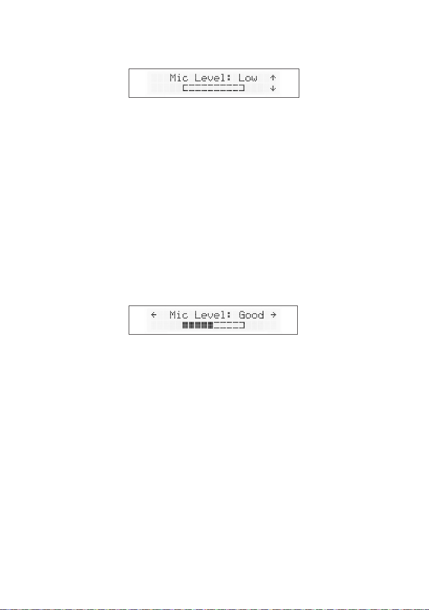
Microphone Input
The hearing loop driver’s Microphone Input section displays the
microphone input level within a range of 47dB.
The top line of the display indicates if the correct microphone input
level has been achieved:
• “Low” indicates the microphone level is too low for the automatic
gain control to operate.
• “Good” indicates the microphone level is at an optimum level for
the automatic gain control to operate.
• “High” indicates the microphone level is too high and signal
clipping may occur. Signal clipping will also be shown by the LED.
Adjustments
It is recommended that at least 5 blocks in the adjustment block are
lled (see the above image for an example).
Enter Adjustment Mode and alter the microphone input level
displayed on the bar until the text displays ‘Good’:
• To increase the microphone input level, rotate the control dial
clockwise.
• To decrease the microphone input level, rotate the control dial
anti-clockwise.
• Press the control dial once to conrm the selection and return to
the main menu.
19
Page 20
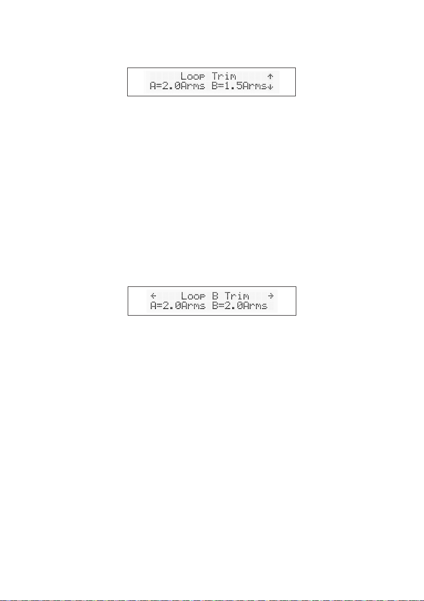
V15a Only: Loop Trim
When using a V15a, the hearing loop driver’s Loop Trim function
allows Loop B’s output to be adjusted relative to Loop A’s output.
Please note: This section is only available on the V15a. The equivalent
V7 and V15 menu displays Current Output, to which adjustments can
be made using the Loop Output section (see page 16).
-
When in the Loop Trim section, adjustments are made in 1dB steps.
The measured loop output current is displayed in amps RMS (accurate
for sine signals).
Adjustments
Enter Adjustment Mode to alter “Loop B Trim” relative to “Loop A”.
• To increase the Loop B Trim level, rotate the control dial clockwise.
• To decrease the Loop B Trim level, rotate the control dial
anti-clockwise.
• Press the control dial once to conrm the selection and return to
the main menu.
20
Page 21
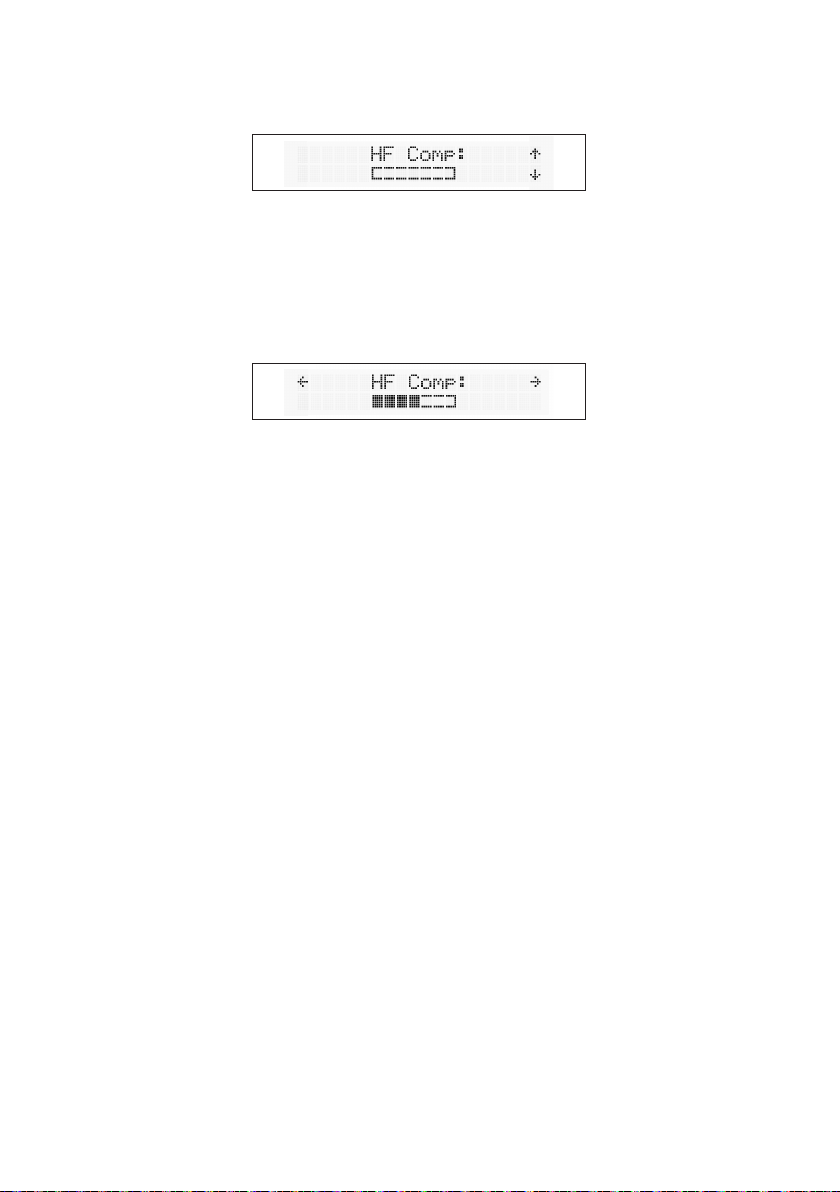
High-Frequency Compensation
There are 7 levels of high-frequency compensation available to adjust
for metal loss. Your hearing loop driver will have high-frequency
compensation turned to the lowest setting as its default.
Adjustments
To alter the high frequency compensation level, enter Adjustment
Mode:
• To increase the high-frequency compensation level, rotate the
control dial clockwise.
• To decrease the high-frequency compensation level, rotate the
control dial anti-clockwise.
• Press the control dial once to conrm the selection and return to
the main menu.
To calculate the correct high-frequency compensation level, refer to
Set-Up on page 22.
21
Page 22

Set-Up
To ensure optimal performance of a V7, V15 or V15a hearing loop
driver, set-up should be performed in following order:
Step 1: Background Noise Level (see page 23)
Step 2: Metal Loss (see pages 24-25)
Step 3: Output Level and Clipping (see page 24-25)
Step 4: Field Uniformity (see page 25-26)
Step 5: Final Output Level Adjustment (see page 26)
Step 6: Input Signal Level Adjustment (see page 26)
Required for Set-Up
• TSG - Contacta Test Signal Generator (TSG1)
• FSM - Contacta Field Strength Meter (IL-CONTACTA-FSM)
• Tripod or similar for mounting the FSM is recommended
• ‘Compliance Certicate’ document
Note:
Throughout set-up, record values on the provided Compliance
Certicate document whenever you see the following icon:
The Compliance Certicate document conrms compliance with
IEC-60118:4 if your values are within acceptable levels.
It is highly recommended that you retain a copy of the completed
Compliance Certicate document for your records and provide a copy
to the relevant facilities manager.
22
Page 23
Step 1: Background Noise Level
This test should be performed prior to loop installation.
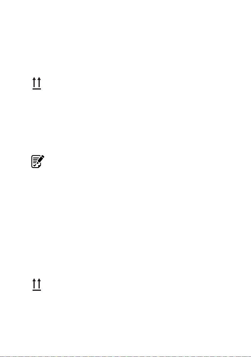
1. Set up the FSM, ensuring that the two vertical arrows in the
top-right corner of the device are placed at the correct height:
• 1.2 metres (3’ 9”) for seated user.
• 1.7 metres (5’ 6”) for standing users.
A tripod or similar for mounting the FSM is recommended.
2. Any lights or equipment normally active in the surrounding area
should be turned on to ensure an accurate testing environment.
3. Set the FSM to the Background Noise mode – “A-weighted”.
4. Measure and note the background noise level throughout the
looped area on the Compliance Certicate document.
5. Listen to the loop through the FSM (A-weighted) or a loop listener
(A-weighted). Note and demonstrate any interference to the
customer which may not be heard through a hearing instrument.
6. Background magnetic noise must be between -32dB and -60dB. If
the readings noted pass the Compliance Certicate document’s
requirements, move on to Step 2: Metal Loss.
Step 2: Metal Loss
1. Set up the FSM, ensuring that the two vertical arrows in the
top-right corner of the device are placed at the correct height:
• 1.2 metres (3’ 9”) for seated user.
• 1.7 metres (5’ 6”) for standing users.
A tripod or similar for mounting the FSM is recommended.
2. Connect the TSG to the line input of the hearing loop driver.
23
Page 24
3. Set the TSG to the 1kHz setting.
4. Set the FSM to the Third Octave F= 1000Hz setting.
5. Adjust the line level until “Good” is displayed.
6. Adjust the drive level to achieve 2 amps of output current.
7. Set the TSG to the pink noise setting and record the value
measured by the FSM.
8. Set the FSM to the Third Octave F= 100Hz setting and record
the value measured.
9. Set the FSM to the Third Octave F= 5000Hz setting and
record the value measured.
10. If the dierence between the values measured at 1000Hz and
5000Hz is less than 3dB, record the results and move on to
Step 3: Output Level and Clipping. If the dierence is higher than
3dB, move on to step 11.
11. Increase the HF comp and repeat steps 3 to 10.
Step 3: Output Level and Clipping
Note: This test should be performed as briey as possible.
1. Set the TSG to the 1kHz setting.
2. Set the FSM to the RMS/Peak A-Weighted mode.
3. Adjust the drive level to achieve 2 amps of output current.
4. Measure the eld strength. Achieve 0dB by using the FSM’s
indicated eld strength to work out the extra current required. For
example: if the measured eld strength on the FSM is (A-RMS)
-6dB then 6dB (2X) extra current will be required to achieve 0dB
(see Note 1 on page 27).
Note: If more than 7.9dB is required to achieve 0dB, a dierent
24
Page 25
loop design or more powerful driver is required. This is potentially
due to metal loss.
5. Briey alter the current to the desired level. For instance, the
example in step 4 requires 4 amps of current.
6. The eld strength will now be 0dB +/- 1dB.
7. Quickly record the current required to achieve 0dB eld
strength. Now switch the TSG to 1.6kHz.
8. Conrm that the Loop A and Loop B Clip LEDs remain unlit.
10. If the driver’s front panel Clip LEDs remain unlit, return the TSG to
1kHz and reduce output current to 2 amps move on to Step 4: Field
Uniformity.
If the driver’s front panel Clip LEDs are lit, the driver is clipping.
This means the loop connected is too long, and therefore:
1. The system is not IEC60118-4 compliant.
2. The sound will be distorted.
3. The driver may be susceptible to damage and warranty voided.
Perform one of the following solutions and repeat until there is no
clipping:
1. Reduce the loop current,
2. Reduce the length of the loop,
3. Use a higher diameter of at cable,
4. Try a two-turn loop,
5. Use a higher voltage driver.
Step 4: Field Uniformity
1. Set up the FSM. Ensure that the two vertical arrows in the top-right
corner of the FSM are placed at the correct height:
• 1.2 metres (3’ 9”) for seated user.
• 1.7 metres (5’ 6”) for standing users.
A tripod or similar for mounting the FSM is recommended.
25
Page 26

2. Reduce the loop output current to 2 amps.
3. Set the FSM to the RMS/Peak A-Weighted mode and record
the value measured by the FSM in the centre of the loop.
4. Move the FSM to other user positions within the looped area
and record the values measured by the FSM.
5. The dierences measured in other positions should not be greater
than +/- 3dB of that measured in the rst position.
6. Repeat steps 3 to 5 to create a suitable map of the area looped.
Step 5: Final Output Level Adjustment
1. Set the TSG to 1kHz.
2. Adjust the output current to the level recorded in Step 3: Output
Level and Clipping (7) on page 25. Once the current is set,
disconnect the TSG.
Step 6: Input Signal Level Adjustment
1. Connect the system signal source.
2. Adjust the input level (line/mic) level until “Good” is displayed on
audio peaks.
3. The system is now set up.
26
Page 27
Note 1:
When adjusting the output current, if a level of 2.5 amps is reached
and yet the field strength is still below -6dB, the correct eld
strength will not be achieved.
This is caused by either an incorrect loop design or installation, more
metal loss than expected or an incorrectly specied driver.
There is no need to go higher than +0dB ARMS.
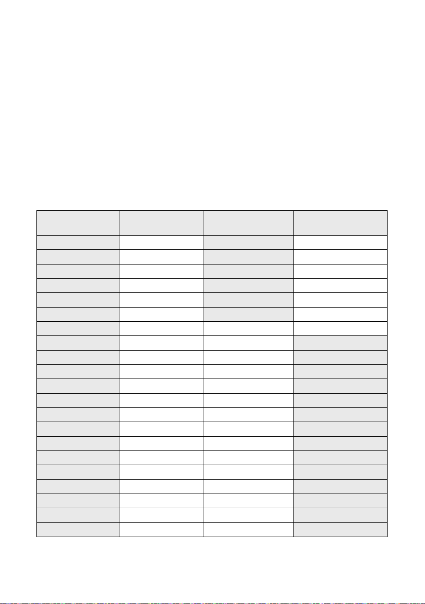
Adjustment to drive current/level required based on the measured
field strength:
Measured Field
Strength
6.00dB 1.00A 6
5.00dB 1.12A 5
4.00dB 1.26A 4
3.00dB 1.42A 3
2.00dB 1.59A 2
1.00dB 1.78A 1
.00dB 2.00A 0 0
-1.00dB 2.24A 1
-2.00dB 2.52A 2
-3.00dB 2.83A 3
-4.00dB 3.17A 4
-5.00dB 3.56A 5
-6.00dB 3.99A 6
-7.00dB 4.48A 7
-8.00dB 5.02A 8
-9.00dB 5.64A 9
-10.00dB 6.32A 10
-11.00dB 7.10A 11
-12.00dB 7.96A 12
-13.00dB 8.93A 13
-14.00dB 10.02A 14
Output current that
will achieve 0dB
Steps to
increase Drive
Steps to
decrease Drive
27
Page 28
Troubleshooting
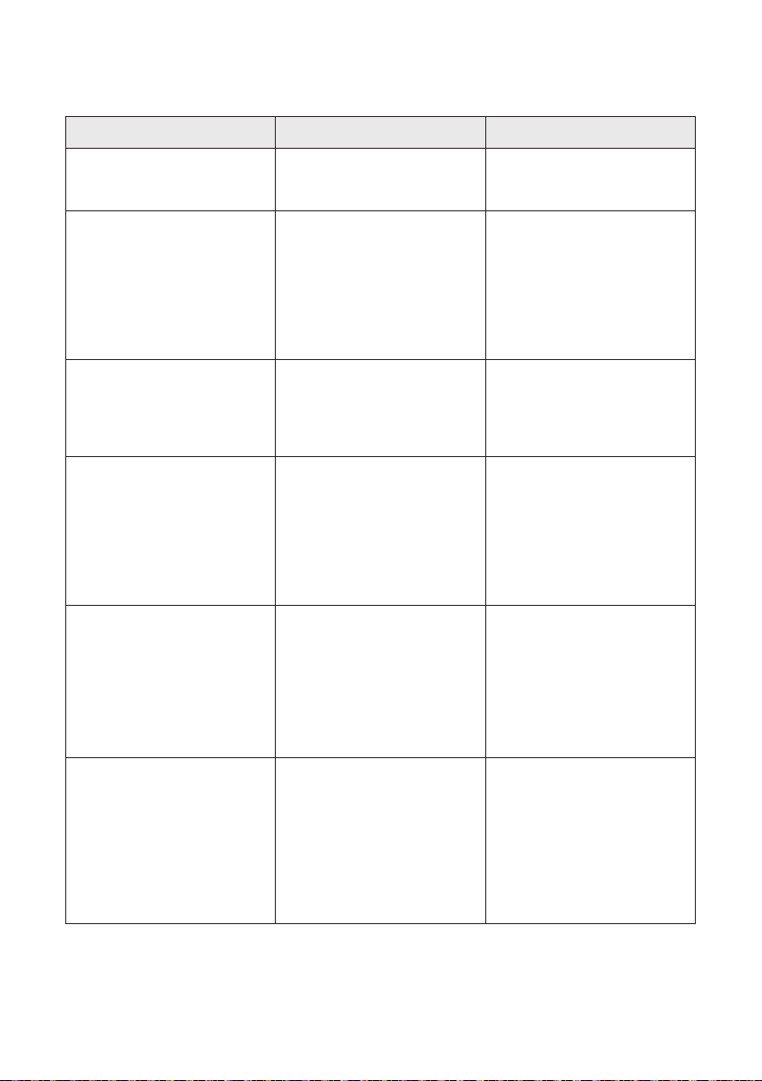
Symptom Possible Fault Action
The driver does not turn on. 1) Mains power is absent.
2) Internal failure.
Interference (buzzing/
whistling/hissing) is heard
through induction loop.
The driver is excessively hot
to touch.
The loop output level
indicates current is owing
but I hear nothing in the loop.
The sound is distorted. 1) Input level has been turned
1) Bad input signals.
2) Internal failure.
1) Large amount of mains hum
present on input.
2) Internal failure.
1) Shorted feeder cable.
2) Loop listener is not
working or being used too far
from loop.
up too high for signal level at
input.
1) Check mains power.
2) Seek assistance.
1) Power o the hearing
loop driver and conrm
that interference isn’t from
external origin.
2) Disconnect input signals.
If sound disappears, check
inputs.
1) Check input signal source.
2) Incorrect hearing loop
driver being used.
1) Check feeder cable,
although the hearing loop
driver will usually refuse to
tune to shorted feeder.
2) Check listener and location.
1) Reduce input level setting.
2) Input signal is distorted.
3) Output signal is clipping.
The Clipping Status Lights
are lit.
Please contact your distributor (or Contacta if appropriate) if you are experiencing technical
diiculties with the product.
The connected hearing loop is
too long.
2) Check signal source.
3) Refer to “The Clipping
Status Lights are lit” below.
1) Reduce the length of the
loop.
2) Use a larger diameter
cable.
3) Create a two-turn loop.
4) Use a higher voltage driver.
28
Page 29

Technical Specication
V7:
Power
2.1mm 30W 14Vdc 2.14A via External PSU (PS-55)
Class 6 External PSU (100V -240V AC 50Hz-60Hz)
Inputs
1 X Line XLR or 3.81mm Euro-block [optimised for -10dBV to 0dBv]
1 X Microphone (12V phantom power via 680Ω) [optimised for levels above -45dBv]
Output Characteristics
Output Voltage: 7.5Vrms (21.21Vpk-pk) @ 5Arms (14.14Apk-pk)
Output Current: 5Arms (14.14Apk-pk) up to 300 seconds
Loop Connector: 5.08mm Euro-block
Audio system
Frequency Response: 80Hz to 6.5kHz
Distortion: THD+N <1% (-40dB)
AGC: Peak detecting
HF Comp: 7 optimised stages
Note 1: Z=1.4Ω (133uH +0.685Ω @ 1.6kHz) Note 2: < 1% (-40dB) distortion
Display & Control
Display: LED Backlit LCD display
Control: Single rotary control
Fault Monitoring and Protection
Main Display: Open circuit loop (DCR measurement)
Loop ground fault
Front Panel LED: Output voltage clipping
Cooling: Internal heatsinks with thermal protection
Physical
Height: 42mm (1.65”)
Depth: 132mm (5.20”) [150mm (5.90”) including XLR and control knob]
Width: 198mm (7.80”)
Weight: 938g (2.06lbs)
see notes 1 and 2
29
Page 30

Technical Specication
V15:
Power
2.1mm 100W 24Vdc 4.17A via External PSU (PS-60)
Class 6 External PSU (100V -240V AC 50Hz-60Hz)
Inputs
1 X Line XLR or 3.81mm Euro-block [optimised for -10dBV to 0dBv]
1 X Microphone (12V phantom power via 680Ω) [optimised for levels above -45dBv]
Output Characteristics
Output Voltage: 15Vrms (42.3Vpk-pk) @ 5Arms (14.14Apk-pk)
Output Current: 5Arms (14.14Apk-pk) up to 300 seconds
Loop Connector: 5.08mm Euro-block
Audio system
Frequency Response: 80Hz to 6.5kHz
Distortion: THD+N <1% (-40dB)
AGC: Peak detecting
HF Comp: 7 optimised stages
Note 1: Z=3Ω (265.4uH + 1.37Ω @ 1.6KHz), Note 2: 1% (-40dB) distortion
Display & Control
Display: LED Backlit LCD display
Control: Single rotary control
Fault Monitoring and Protection
Main Display: Open circuit loop (DCR measurement)
Loop ground fault
Front Panel LED: Output voltage clipping
Cooling: Internal heatsinks with thermal protection
Physical
Height: 42mm (1.65”)
Depth: 132mm (5.20”) [150mm (5.90”) including XLR and control knob]
Width: 198mm (7.80”)
Weight: 938g (2.06lbs)
see notes 1 and 2
30
Page 31

Technical Specication
V15a:
Power
2.1mm 100W 24Vdc 4.17A via External PSU (PS-60)
Class 6 External PSU (100V -240V AC 50Hz-60Hz)
Inputs
1 X Line XLR or 3.81mm Euro-block [optimised for -10dBV to 0dBv]
1 X Microphone (12V phantom power via 680Ω) [optimised for levels above -45dBv]
Output Characteristics
Output Voltage: 15Vrms (42.3Vpk-pk) @ 5Arms (14.14Apk-pk)
Output Current: 5Arms (14.14Apk-pk) up to 300 seconds
Loop Connector: 5.08mm Euro-block
Audio system
Frequency Response: 80Hz to 6.5kHz
Distortion: THD+N <0.3% (-50.5dB) Full current both outputs driven
AGC: Peak detecting
HF Comp: 7 optimised stages
Note 1: Z=3Ω (265.4uH + 1.37Ω @ 1.6KHz), Note 2: 1% (-40dB) distortion
Display & Control
Display: LED Backlit LCD display
Control: Single rotary control
Fault Monitoring and Protection
Main Display: Open circuit loop (DCR measurement)
Loop ground fault
Front Panel LED: Output voltage clipping
Cooling: Internal heatsinks with thermal protection
Physical
Height: 42mm (1.65”)
Depth: 132mm (5.20”) [150mm (5.90”) including XLR and control knob]
Width: 198mm (7.80”)
Weight: 978g (2.15lbs)
see notes 1 and 2
31
Page 32
Standards
EMC
• BS EN 55103-1: 2009 (EMC emissions)
• BS EN 55103-2: 2009 (EMC immunity)
This product has been designed and tested to comply with the following North American and
Canadian standards:
• FCC class “B” EMC (emissions)
• ICES-003
This device complies with Part 15 of the FCC Rules. Operation is subject to the following two
conditions: (1) this device may not cause harmful interference, and (2) this device must accept any
interference received, including interference that may cause undesired operation.
CAUTION: Changes or modications not expressly approved by Contacta Systems LTD or an
authorised partner could void the user’s authority to operate the equipment.
Correct disposal of this product
This marking indicates that this product should not be disposed with other household waste
throughout the EU. To prevent possible harm to the environment or human health from
uncontrolled waste disposal and to conserve material resources, this product should be recycled
responsibly. To dispose of your product, please use your local return and collection systems or
contact the retailer where the product was purchased.
32
Page 33

333435
Page 34

Page 35

Page 36
Local dealer:
UK & ROW
+44 (0) 1732 223900
Contacta Systems Ltd.
Oice 13, Dana Trading Estate
Transfesa Road
Paddock Wood, Tonbridge
TN12 6UT
www.contacta.co.uk
US & Canada
+1 616 392 3400
36
 Loading...