

Page 1
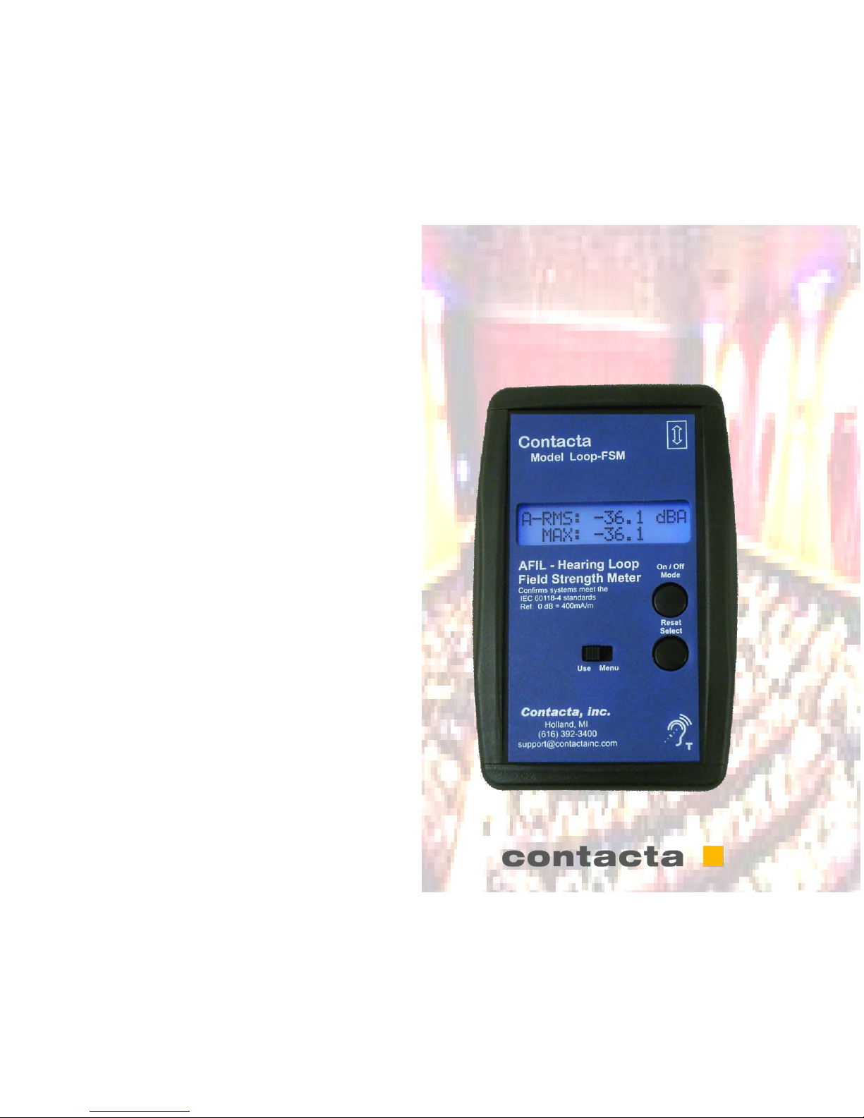
Model - LOOP - FSM
User Manual
Audio Frequency Induction Loop Field Strength Meter
Page 2

2
CONTENTS
Meter Design goals 2
Meter Operation Basics 3
Background Noise Tests 4
Program RMS/Peak Levels 5
Evaluating Frequency Response 6
Headphone/Flat spectrum output 7
Line In Flat Response 8
Meter Specifications / Calibration 9
Thank you for choosing our Field Strength Meter. It has been designed
to ensure that Hearing Loop (Induction Loop) Systems be installed and certified
to the new IEC 60118-4 standard. When these standards are met the user experience will be of equal quality wherever they have the opportunity to use their Tcoils. Our design team interviewed many installers throughout the industry which
resulted in the following design goals:
1. Very accurate and easy to read
2. Simple/straightforward operation
3. Based on the IEC 60118-4 specification
4. Headphone output
5. Flat spectrum output
6. Built to last and be reliable
As you follow through this manual, we will review how the meter should be used
to certify that the requirements of the IEC specification have been met.
Again, Thank you
Contacta Design and Engineering Team
Meter Design Goals
9
Meter Specifications:
Measurement Range: -62dB to +9dB (0dB = 400mA/m)
True-RMS Crest Factor: <3
Resolution: <0.1dB resolution for levels
over –32dB
Displayed resolution: 0.1 dB
Detection Type: True RMS on all features
Sensor: Pickup Coil
Direction of Sensitivity: Length-wise of meter ’s longer dimension
and Parallel to meter face (Position noted
on Product)
Calibration: Calibrated at 1,000 Hz (sine) to read 0
dB at 5.03 mG
Frequency Response: Flat ±1dB from 50 Hz to 10,000 Hz
A-Weighted: Class 2 meter specified in IEC 61672-1
Power Source: Single 9v Battery & External Power
Jack
Headphone Jack: Output A-Weighted or Flat selectable
Display: 16x2 LCD Character Display
Backlight: Variable brightness blue LED
Calibration and Warranty:
This meter has been calibrated with equipment that is traceable back to the National Bureau
of Standards. Under general use this meter should not require regular calibration, however if
you return the unit to Contacta, the calibration can be checked and supplied with a calibration
curve. Please call to get a service number and check the costs involved.
Contacta, Inc. 332 E. Lakewood Blvd #400, Holland, MI 49424 Phone: (616) 392-3400
Email: [email protected].
This meter is warranted to be free of component, design and manufacturing defects for a
period of one year. Contacta accepts no responsibility for system designs or installations
where this meter was used for test and calibration purposes. Please contact us if you have
any questions. Thank you.
Page 3
8
Line In Flat Response Mode:
On the top of the unit is a new feature, audio dBV
level. The readings and the display help determine
what level of signal is Coming from the house feed.
Levels between -10dBV and +4dBV are considered
to be line level signals. Often a poor loop system
Sound comes from a very low level facility feed.
This input uses the last mode on the FSM and displays an accurate level which can then be demonstrated to the facility. We prefer a level between 10dBV and 0dBV.
To use this feature cycle through the various mode
until you see Line In Flat Response on the display.
Now connect up the XLR adapter which has an
XLR female on one end and an 1/8” TRS connector
on the other end. If you wish to make up your own
adapter use the following information.
1/8 in TRS connector XLR female connector
Tip --------------------------------------------- Pin 2
Ring ------------------------------------------ Pin 3
Sleeve ---------------------------------------- Pin 1
3
Meter Operation Basics
Turning the meter ON and Off
On - Press and hold button A until the screen lights
Off - Press and continue to hold button “A” until the Powering
Down process is finished and the screen goes dark
Selecting the meter mode
When you press Button “A” it first displays the current mode
and the next press advances to the next meter mode:
1. Background Noise Test with Max indication
2. Signal Strength “A weighted” RMS / Peak
3. Field Strength “Flat” RMS / Max
4. Third Octave Levels 100, 200, 500, 1K, 2.5K, 5KHz
“B” Button functions
In modes 1 - 3 pressing the “B” button reset the
MAX or PEAK readings
In mode 4 pressing the “B” button advances the
center frequency of the third octave filters
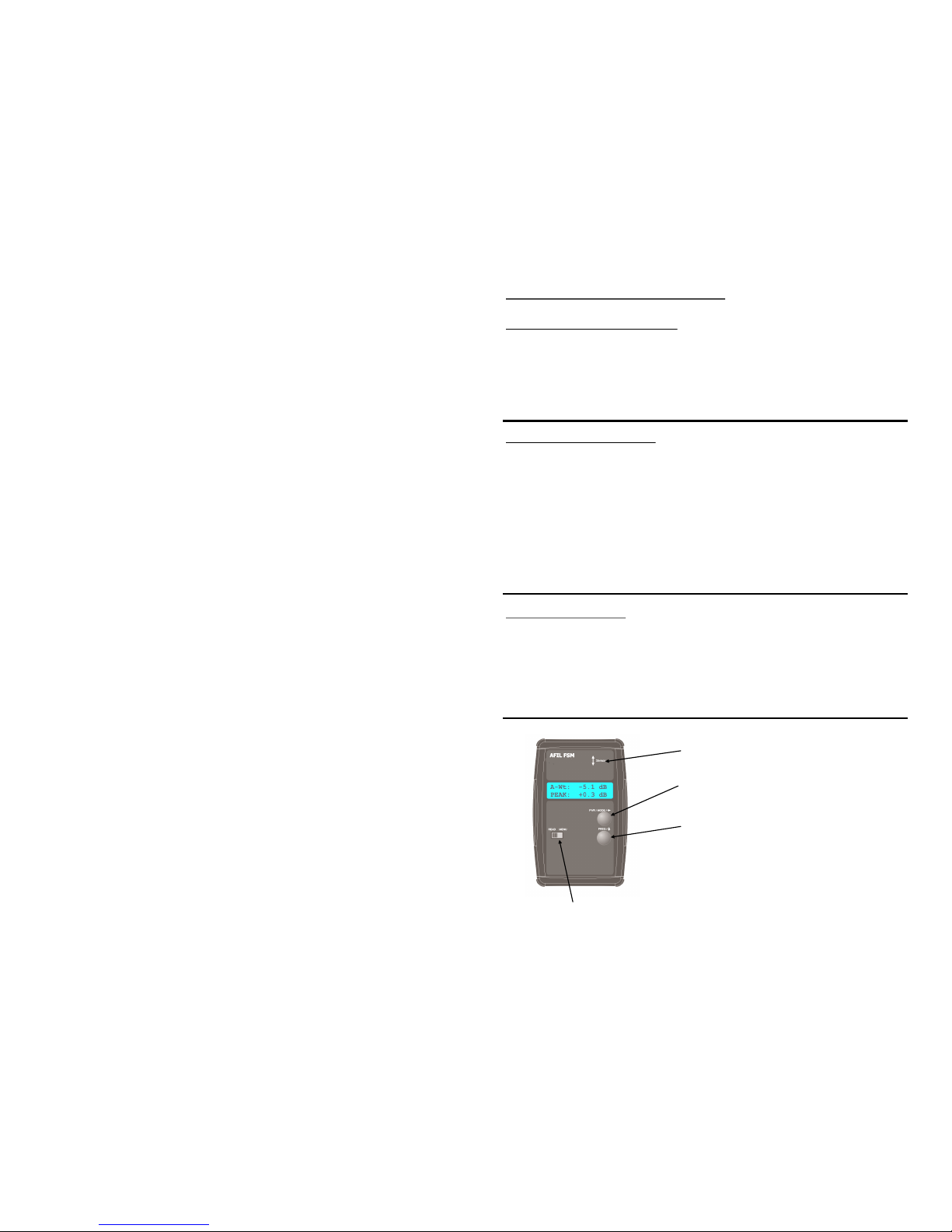
Sensor Location
Button “A” On/Off and Mode con-
trol
Button “B” Reset/Select and Fre-
quency advance
Use / Menu
Switch
Page 4
4
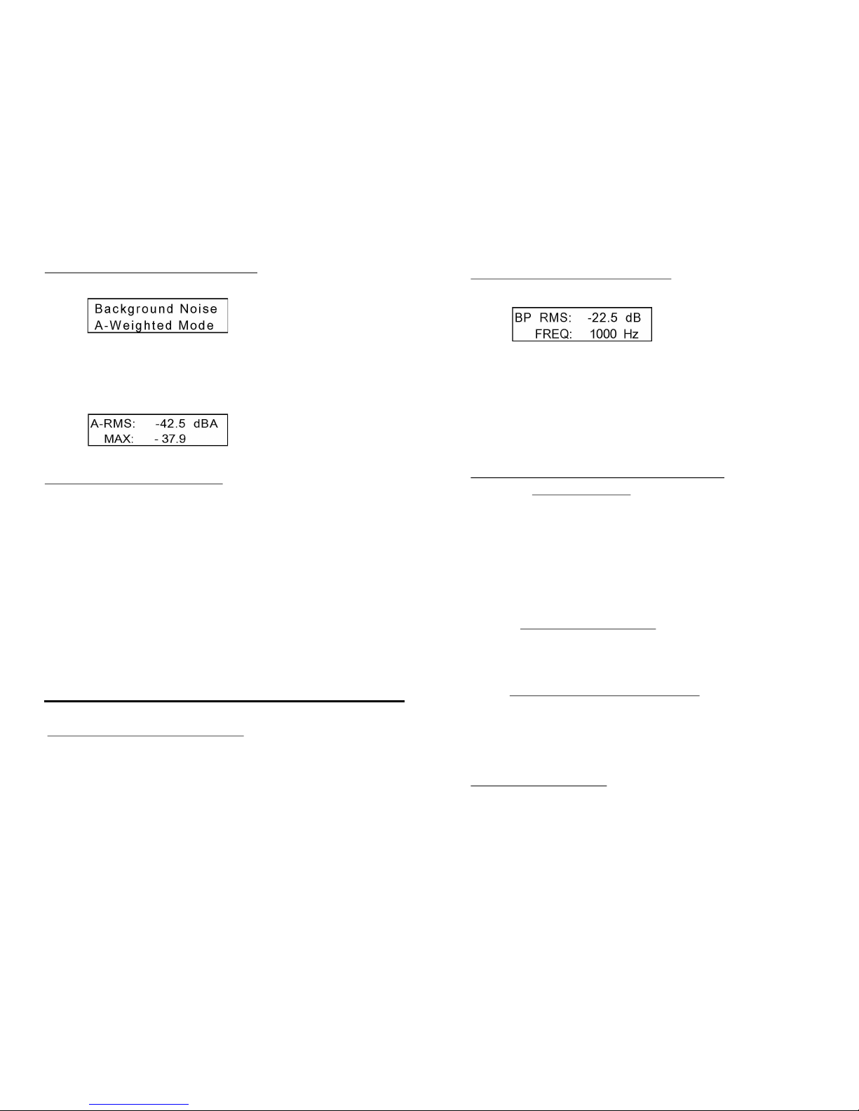
Background Noise Level Test
After turning the meter on it comes up in the Background
Noise “A weighted” measurement mode. The display will indicate
the RMS reading on the first line and the MAX reading on the second
line. Pressing button “B” resets the MAX reading.
How to test for background noise:
When testing a new facility for background noise first turn on
all lights, fans, sound system and other electrical equipment which
is normally on when the facility is in use. Usually the loop system has
not been installed yet, however if you are certifying an installation
this test is done without the hearing loop system turned on.
Walk throughout the seating area where the loop system will
be used, holding the meter in a vertical position at the listening
plane height. The important reading will be the MAX reading, However it is important to watch the RMS reading. If the MAX reading exceeds –32dBA (readings above –32dBA will have a lower negative
number ex. –30dBA means there is more background noise than
–35dBA), you will need to document the areas where those higher
noise levels are found.
IEC 60118-4 Notes and Requirements
The standard as revised in 2004 notes that any background
noise level lower than –47dBA will result in a excellent signal to
noise ratio, however levels below –32dBA are acceptable and do
meet the requirements of the standard. If the background noise level is above –32dBA, then the facility management should be notified
and the source of the interference found and repaired.
7
Method II - Pink noise signal Cont.
Record the RMS level readings for each of the frequencies`.
As in method I if the level does not vary by more than ±3dB the system as installed will meet the IEC specification. This method was
requested by the field engineer so they could run the test with one
instrument without continually adjusting the frequency source. It
also makes it easy to conduct the test in more than one location.
Headphone / Full Spectrum Output
The headphone output jack serves two purposes: First it can
be used to monitor the loop program and gives you an “A Weighted”
output signal that can be listened to with standard 1/8” stereo head-
phones. To change the headphone volume slide the Use/Menu
switch to Menu and use the Mode button to advance to Headphone
Volume. Pressing the Select button advances to the volume adjust
screen where the top button raises the volume and the bottom button lowers it. Once adjusted sliding the switch back to Use will save
the setting.
A full (flat) spectrum output can be sent from this same connector which could then feed a spectrum analyzer. This would show
the signal level at the various frequencies and help to both confirm
proper operation and asses the frequency and level of any interferences.
To switch from “A-Weighted” to Flat: With the meter turned
on slide the Use/Menu switch over to Menu. Press the Mode button
“A” once and you will advance to the Headphone Jack setup screen.
Then pressing the Select button “B” you can choose either A -
Weighted or Flat Spectrum.
Menu Adjustments
In the Menu mode, selected by the slide switch, the following items
can be adjusted: Backlight level, Headphone output type, Headphone volume, Display units (dB, mG, uT) and Power timeout (5 to
30, or none.
Page 5
6
Measuring Frequency Response
Detailed below are two processes that can be used to con-
firm the system properly reproduces all of the required frequencies
equally in the bandwidth of 100 to 5KHz. A test signal generator
such as the Contacta Loop-TSG will be required to perform these
tests and both methods will yield very accurate results.
Method I - Sine wave signal
Send at a minimum the following sine wave signals through
the hearing loop system without adjusting any of the audio or loop
level controls: 100Hz, 250 Hz, 500 Hz, 1000 Hz, 2500 Hz, and 5000
Hz. Using the Flat Spectrum mode record the RMS level generated
by each of these. To meet the IEC specification the levels should not
vary by any more than ±3dB.
Method II - Pink noise signal
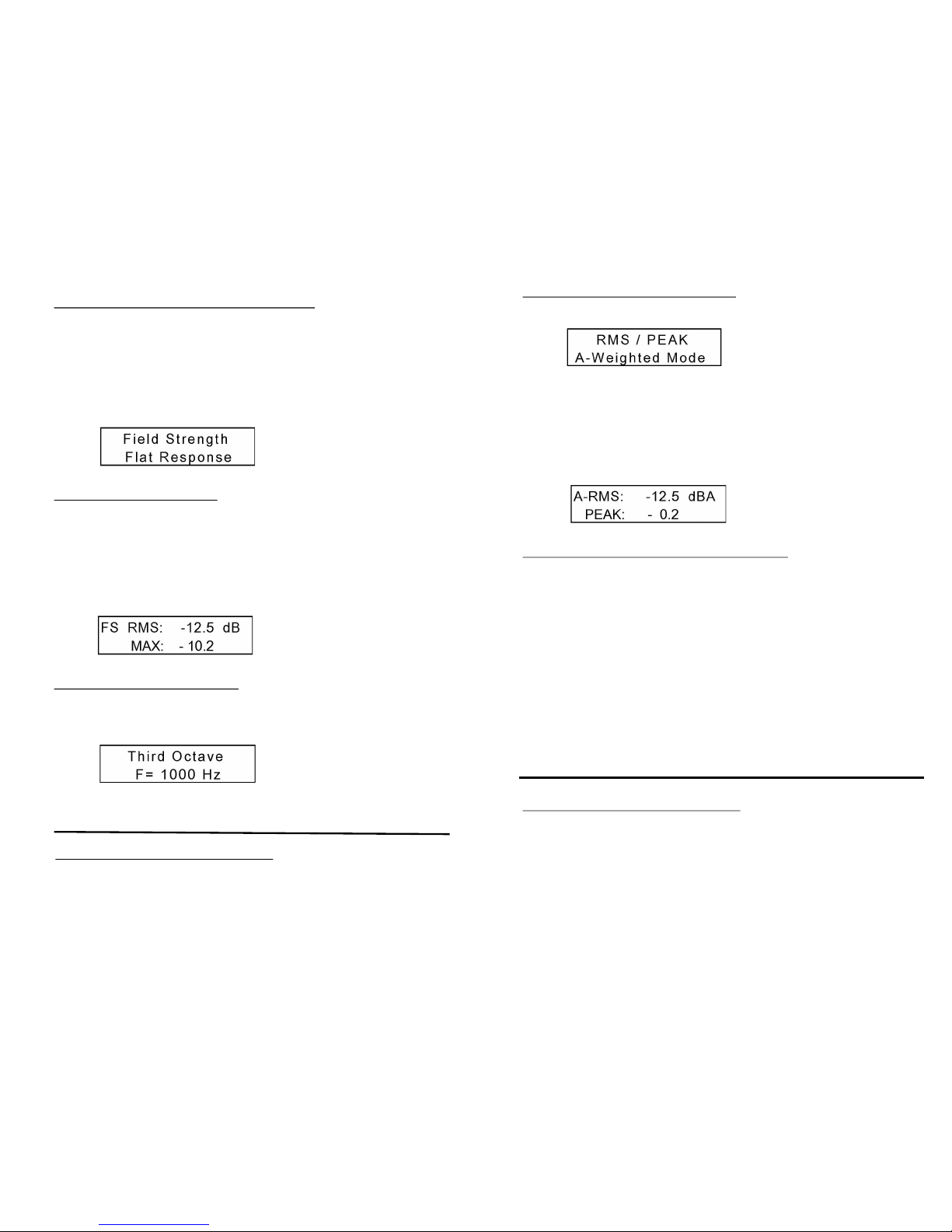
Send a pink noise signal into the hearing loop system and
select the Third Octave mode on the meter. It will initially start at a
1000Hz center frequency.
Pressing button “B” will cycle through the frequencies of
100Hz, 200Hz, 500Hz, 1000Hz, 2500Hz and 5000Hz.
IEC 60118-4 Notes and Requirements
The standard as revised notes that within the frequencies of
100Hz to 5000Hz the hearing loop system should equally reproduce
all signals. At a minimum the systems is to be tested at 100Hz, 1KHz
and 5KHz.
5
Program RMS/Peak Levels
The second mode is used to set up the hearing loop signal
level using an A-Weighted filter. It is very difficult to set the field
strength to an average of –12dBA as it will constantly vary based on
the program used to set up the system. We will use the PEAK read-
ing to confirm that both our design and equipment meet the IEC
specification. Pressing button “B” resets the PEAK reading.
How to test then adjust the loop system level:
Once the hearing loop system has been installed, play some
bandwidth limited (100Hz to 5KHz) pink noise or 1KHz sine (use the
driver manufacturers recommendation) though the loop system.
Walk throughout the audience area holding your meter vertically.
Note the readings and confirm that the A-RMS level does not vary by
more than ± 3dBA. This lets you know that the perceived signal level
in the hearing aids will be the same, no matter where the person is
sitting.
Next: using program audio similar to what is normally used in
the facility, adjust the audio program level to a level just above
“normal”. Now turn on the hearing loop system and adjust the drive
level until a –3dBA to 0dBA PEAK level is obtained in the center of
the loop. Reset the PEAK level and confirm this level averages 0
dBA across the audience listening plane.
IEC 60118-4 Notes and Requirements
The revised standard states that the signal level across the
loop area should not vary by more than ±3dB. Once that is confirmed
the signal level based on the facility’s normal program should peak
at 0 dB as referenced to a 400mA/m. This will confirm there is adequate loop current to produce both the peak and average (Avg. is
-12dB or 100ma/m) signal levels that work well with T-coil equipped
hearing aids.
 Loading...