

Page 1
1
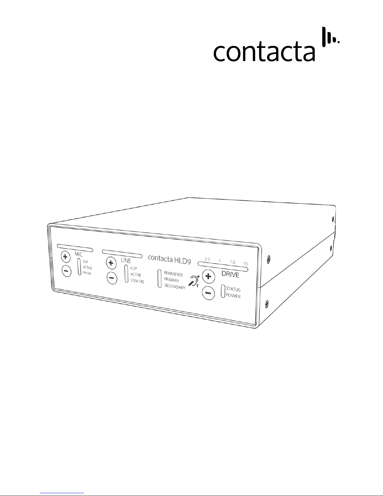
HLD9
User Guide
October 2016
Hearing Loop Driver
Page 2

2
Page 3

3
Contents
Product Overview
Components
Connections
Setting up the Driver
Loop Congurations / Set Up
Troubleshooting
Technical Specication
Warranty
Standards
4
4
5-6
7-9
10-13
14-15
16
17
18
Contacta has a policy of continuous product development, therefore small specication changes
may not be reected in this manual. Images, labels, packaging, accessories and product colours
are subject to change without notice.
Page 4
4
Product Overview
Components
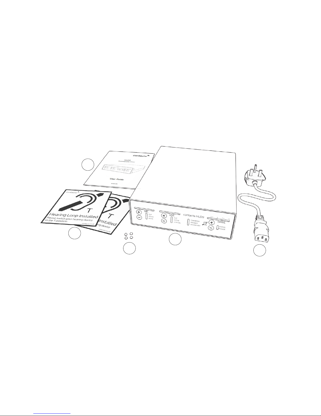
Our HLD9 is a pioneering modular hearing loop driver for perimeter
or phased array congurations, suitable for large area applications
such as theatres, conference facilities, sports arenas, concert halls and
auditoria.
The HLD9 uses cutting edge switching converter technology to deliver
high eicacy and high performance with low noise.
1
2
3
4
5
1. User Guide
2. Hearing Loop Stickers x 2
3. Rubber Feet x 4
4. Hearing Loop Driver (HLD)
5. IEC Power Lead
You will also need: loop cable or at copper tape of a length and
type, which will be determined by the loop design. The driver requires
ancillary equipment for audio feeds, such as a microphone or sound
system. Loop test equipment is also required as detailed on page 8.
Page 5
5
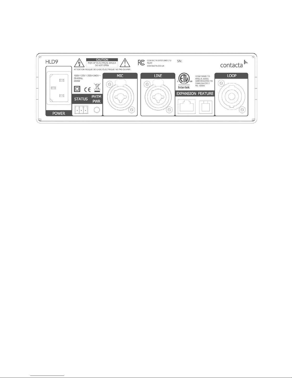
1. Power Supply Input.
Power Sources - This product should be operated only from the type
of power source indicated on the marking label. If you are not sure of
the type of power supply to your home, consult your product dealer or
local power company. The primary method of isolating the amplier
from the mains supply is to disconnect the mains plug. Ensure that the
mains plug remains accessible at all times. Unplug the AC power cord
from the AC outlet if the unit will not be used for several months or
more.
Rear Panel Connections
*
:
Connections
1
2
3
4
5
6
7
8
*HLD9-ETL rear panel text shown. All connections
are the same on the standard HLD9.
2. External Port - Status Indicator (Volt-free relay contacts).
3. Phantom power indication for microphone.
4. Input 1 (Microphone) - Balanced XLR with switchable 12VDC
phantom power or ¼” unbalanced TRS jack for electret microphone
with 5VDC power via 680Ω load.
5. Input 2 (Line) - Balanced XLR or ¼” TRS jack to ohmically isolated
input.
6. Expansion.
CAUTION: For connection to other Contacta systems only.
7. Feature - External monitor & control, Contacta communications
processor.
CAUTION: This is not a telecommunications port.
8. NL4 Loop Output Connection.
Page 6
6
Audio Connections:
2 1
3
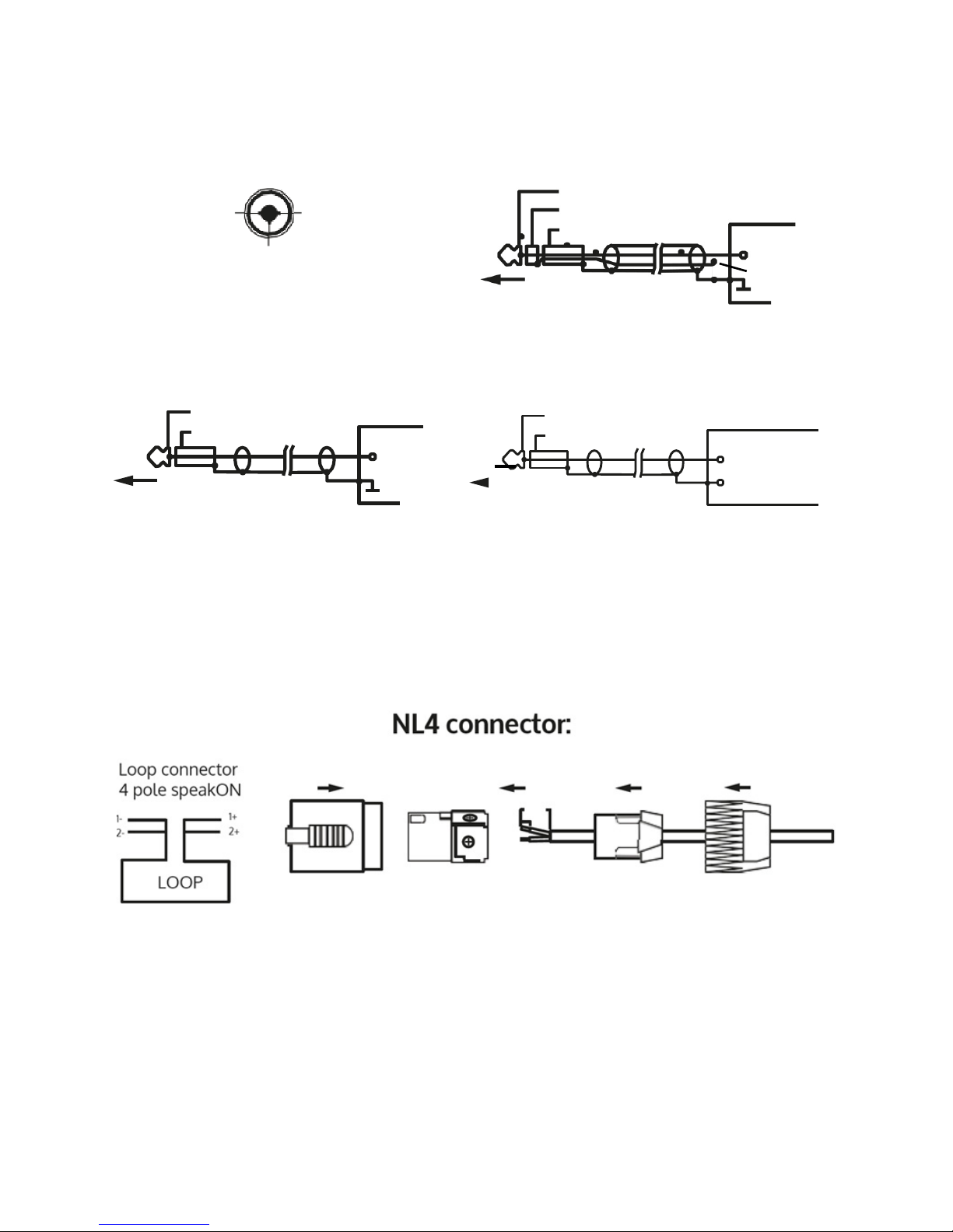
Mic & Line
XLR connector
1: Screen/Shield
2: + (Signal Hot)
3: - (Signal Cold)
Mic
Unbalanced TRS Jack
Tip
Ring
Sleeve
SOURCE
+ (Signal)
GND
Mic
Unbalanced Mono TS Jack
Tip
Sleeve
SOURCE
+ (Signal)
GND
Line
Unbalanced Mono TS Jack
Tip
Sleeve
SOURCE
+ (Signal) hot
- (Signal) cold
Phantom Power
CAUTION: Route loop output cables as far away as possible from the
driver audio input cables.
Connect a twisted pair or quad core loop feeder cables to the supplied
NL4 connector (diagram below). Insert into Output Channel A/B
sockets on the rear of the driver.
Loop Connections:
Page 7
7
Setting up the Driver
CLIP
ACTIVE
PHTM
CLIP
ACTIVE
LOW SIG
STATUS
POWER
MICLINEDRIVE
PERIMETER
PRIMARY
SECONDARY
2.5 5 7.5 10
contacta HLD9
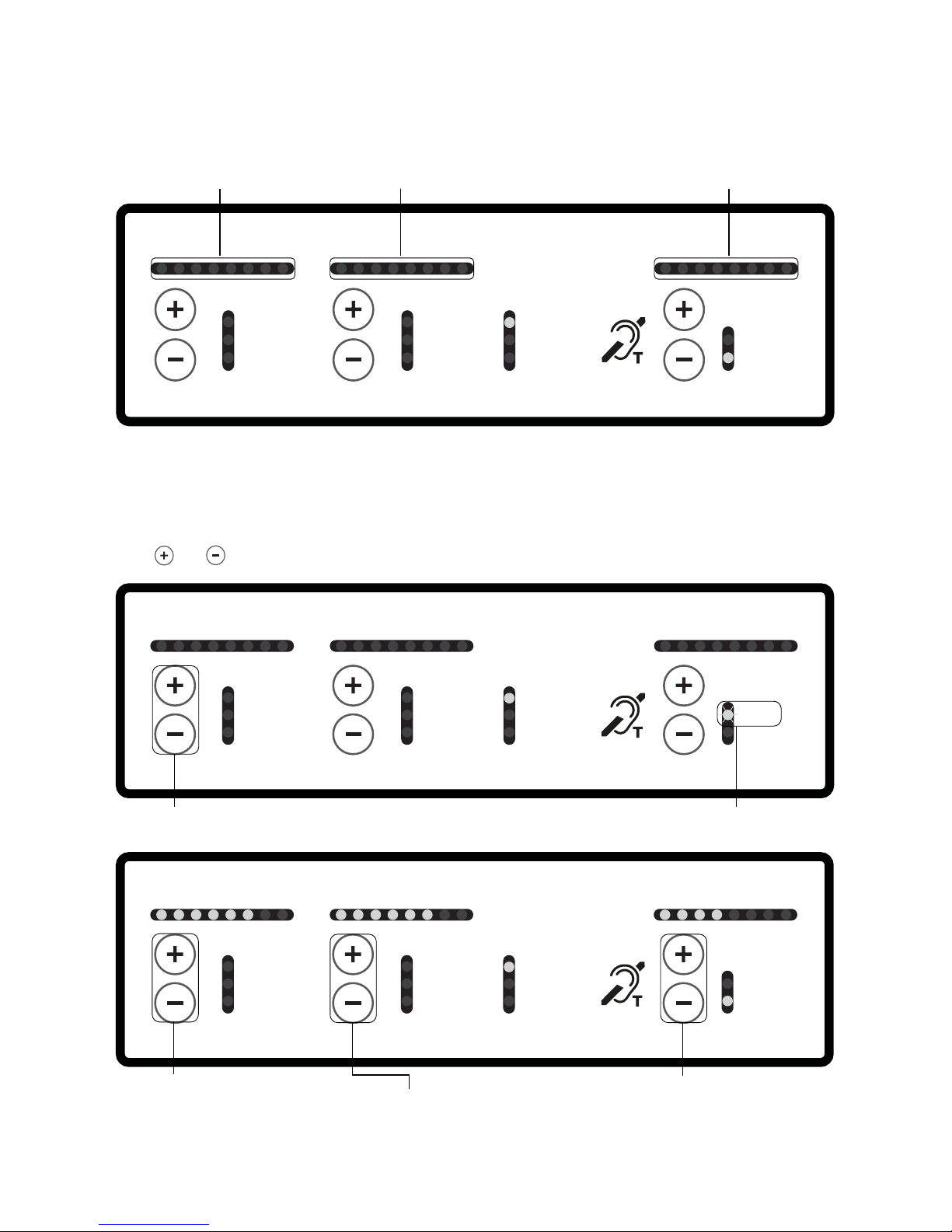
Shows MIC level Shows LINE level Shows DRIVE level
Driver Modes:
Normal Operation Mode – The driver is fully functional. However, the
controls on the front do not change the driver operation.
Adjustment Mode – In this mode one can adjust all of the levels using
the + or – buttons.
CLIP
CLIP
MICLINEDRIVE
PERIMETER
2.5 5 7.5 10
contacta HLD9
CLIP
ACTIVE
PHTM
CLIP
ACTIVE
LOW SIG
STATUS
POWER
MICLINEDRIVE
PERIMETER
PRIMARY
SECONDARY
2.5 5 7.5 10
contacta HLD9
CLIP
ACTIVE
PHTM
CLIP
ACTIVE
LOW SIG
STATUS
POWER
MICLIN
ED
RIVE
PERIMETER
PRIMARY
SECONDARY
2.5 5 7.5 10
contacta HLD9
To enter adjustment mode press
both MIC + and - simultaneously
In adjustment mode the
STATUS LED will ash
Front Panel Overview:
CLIP
ACTIVE
PHTM
CLIP
ACTIVE
LOW SIG
STATUS
POWER
MICLIN
ED
RIVE
PERIMETER
PRIMARY
SECONDARY
2.5 5 7.5 10
contacta HLD9
Pressing the MIC + or - will
adjust the MIC input gain;
adjustments are in 1dB steps.
LEDs show the MIC’s level
after fader
Pressing the LINE + or - will adjust the
LINE input gain; adjustments are in 1dB
steps. LEDs show the LINE level after
fader. If input is low the LOW SIG LED
will illuminate
Pressing the Drive + or - will
adjust the Drive output by
1dB steps. LEDs show the
DRIVE level in approx 0.5A
increments
Page 8
8
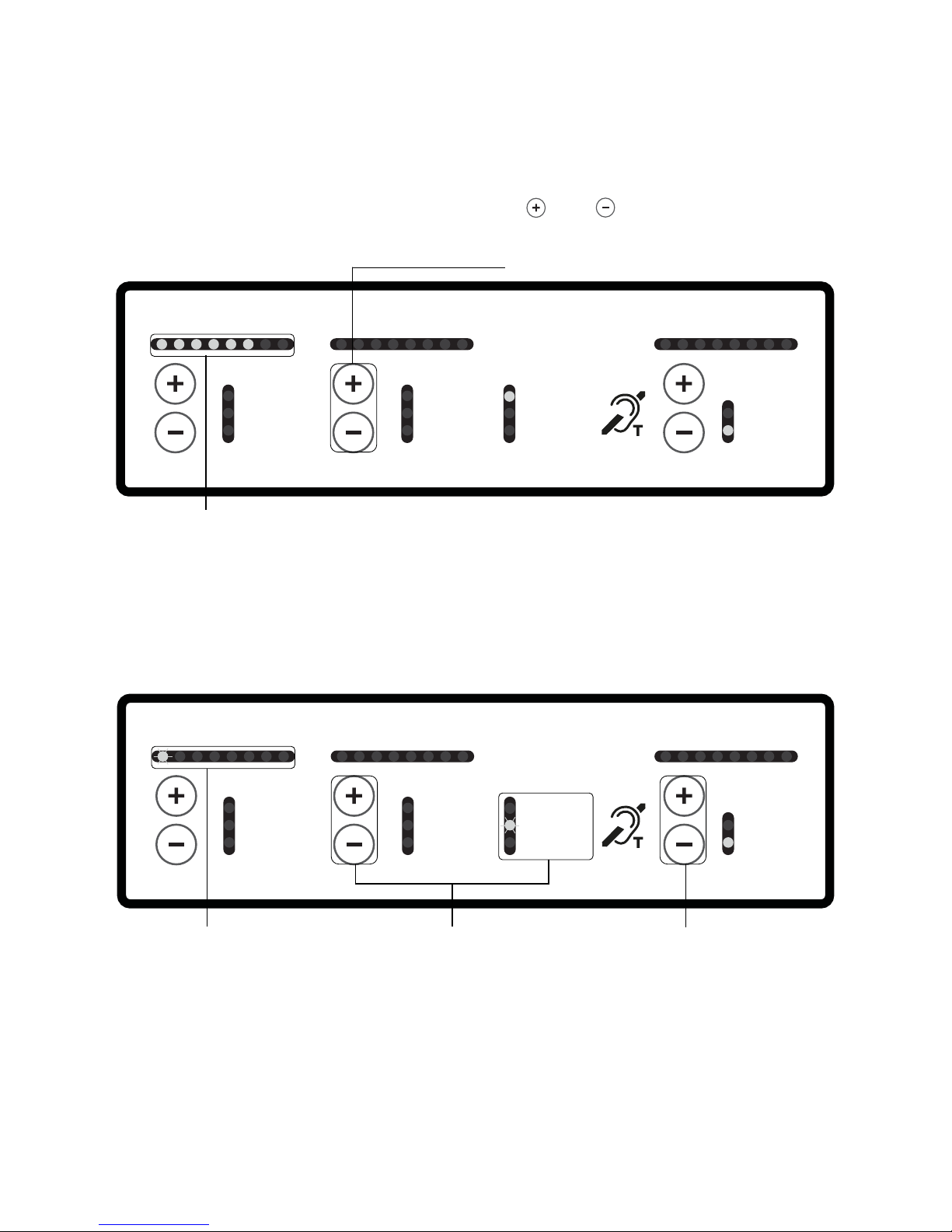
Engineers mode – In this mode there are additional items that can
be adjusted, such as driver type, phantom power and high frequency
compensation.
You must rst be in adjustment mode (see page 7). Then, to enter the
engineers mode, simply press both Line + and - simultaneously.
CLIP
ACTIVE
PHTM
CLIP
ACTIVE
LOW SIG
STATUS
POWER
MICLIN
ED
RIVE
PERIMETER
PRIMARY
SECONDARY
2.5 5 7.5 10
contacta HLD9
Press both Line + and - simultaneously
to enter the Engineers’ mode
PAGE 1 allows you to select the driver operation; either PERIMETER,
PRIMARY or SECONDARY. Always select the driver operation mode
before installing the driver in its rack mount bracket.
CLIP
CLIP
MICLINEDRIVE
PERIMETER
2.5 5 7.5 10
contacta HLD9
CLIP
ACTIVE
PHTM
CLIP
ACTIVE
LOW SIG
STATUS
POWER
MICLINEDRIVE
PERIMETER
PRIMARY
SECONDARY
2.5 5 7.5 10
contacta HLD9
CLIP
ACTIVE
PHTM
CLIP
ACTIVE
LOW SIG
STATUS
POWER
MICLIN
ED
RIVE
PERIMETER
PRIMARY
SECONDARY
2.5 5 7.5 10
contacta HLD9
PAGE 1 is identied by
LED 1 ashing
Pressing the LINE + or - buttons
selects driver operation, Perimeter,
PRIMARY or SECONDARY
When you are ready to move
onto the next PAGE press the
DRIVE + button
There are 5 PAGE settings, each identied by a ashing MIC LED:
PAGE 1 is LED 1, PAGE 2 is LED 2, etc.
Page 9

9
• Pressing the MIC (+ and -) buttons simultaneously will take the
driver back to the normal operation mode where the controls are
non-functional.
• PERIMETER mode, for a single loop or (with a secondary driver)
two widely separated loops.
• PRIMARY mode, the rst and controlling driver of two in a phased
array loop layout.
• SECONDARY mode, the second driver of two in a phased array
loop layout.
• When only this rst light is illuminated and the driver is in the
engineers mode, press either the LINE + or – to change the driver
type from PERIMETER, PRIMARY OR SECONDARY.
• When nished setting up the driver type, press the DRIVE – button
to take the driver out of the engineers mode and put if back into
the adjustment mode. The status light will begin to ash.
CLIP
CLIP
MICLINEDRIVE
PERIMETER
2.5 5 7.5 10
contacta HLD9
CLIP
ACTIVE
PHTM
CLIP
ACTIVE
LOW SIG
STATUS
POWER
MICLINEDRIVE
PERIMETER
PRIMARY
SECONDARY
2.5 5 7.5 10
contacta HLD9
CLIP
CLIP
MICLINEDRIVE
PERIMETER
2.5 5 7.5 10
contacta HLD9
CLIP
ACTIVE
PHTM
CLIP
ACTIVE
LOW SIG
STATUS
POWER
MICLINEDRIVE
PERIMETER
PRIMARY
SECONDARY
2.5 5 7.5 10
contacta HLD9
CLIP
ACTIVE
PHTM
CLIP
ACTIVE
LOW SIG
STATUS
POWER
MICLINEDRIVE
PERIMETER
PRIMARY
SECONDARY
2.5 5 7.5 10
contacta HLD9
Changing the driver type
You must be in engineers mode to change the driver type.
Ensure you have selected PAGE 1.
The three operating modes are:
Page 10

10
Loop Congurations / Set Up
PLEASE NOTE: The loop cable must be connected before powering up
the driver. Upon power up the loop is automatically analysed and set
up. If no loop is connected the status light will be solid red. To RESET
unplug the driver and wait 60 seconds minimum after all lights go out.
Perimeter Loop or Primary Driver Setup*
1. Power up the driver and once the loop analysis (indicated by the
ashing LED sequence) is complete, conrm or select the correct
driver type (PERIMETER or PRIMARY). Instructions on changing driver
type on page 14.
CAUTION: Once the loop (load) has been analysed it should not be
altered or adjusted
2. Enter the adjustment mode by pressing the MIC (+ and - ) buttons
simultaneously until the red status light ashes.
3. While in adjustment mode (red status light ashing) conrm that
the MIC, LINE and DRIVE levels are set to their minimum level by
individually holding in the - button of each for a few seconds.
4. Connect the input signal to the LINE input unless you are directly
connecting a microphone. If testing with our Test Signal Generator
(TSG), connect to the HLD9’s LINE input.
5. For either input signal (in adjustment mode) increase the
appropriate input level by pressing the - button until the rst yellow
LED illuminates (this will be solid if using a sine wave) or occasionally
ash if used on music or speech sources.
6. Bring the DRIVE level up by pressing the DRIVE + button until the
required level is reached.
CLIP
CLIP
MICLINEDRIVE
PERIMETER
2.5 5 7.5 10
contacta HLD9
CLIP
ACTIVE
PHTM
CLIP
ACTIVE
LOW SIG
STATUS
POWER
MICLINEDRIVE
PERIMETER
PRIMARY
SECONDARY
2.5 5 7.5 10
contacta HLD9
CLIP
ACTIVE
PHTM
CLIP
ACTIVE
LOW SIG
STATUS
POWER
MICLINEDRIVE
PERIMETER
PRIMARY
SECONDARY
2.5 5 7.5 10
contacta HLD9
CLIP
CLIP
MICLINEDRIVE
PERIMETER
2.5 5 7.5 10
contacta HLD9
CLIP
ACTIVE
PHTM
CLIP
ACTIVE
LOW SIG
STATUS
POWER
MICLINEDRIVE
PERIMETER
PRIMARY
SECONDARY
2.5 5 7.5 10
contacta HLD9
*
Assumes unit is properly connected and loop has continuity.
Page 11
11
CLIP
ACTIVE
PHTM
CLIP
ACTIVE
LOW SIG
STATUS
POWER
MICLINEDRIVE
PERIMETER
PRIMARY
SECONDARY
2.5 5 7.5 10
contacta HLD9
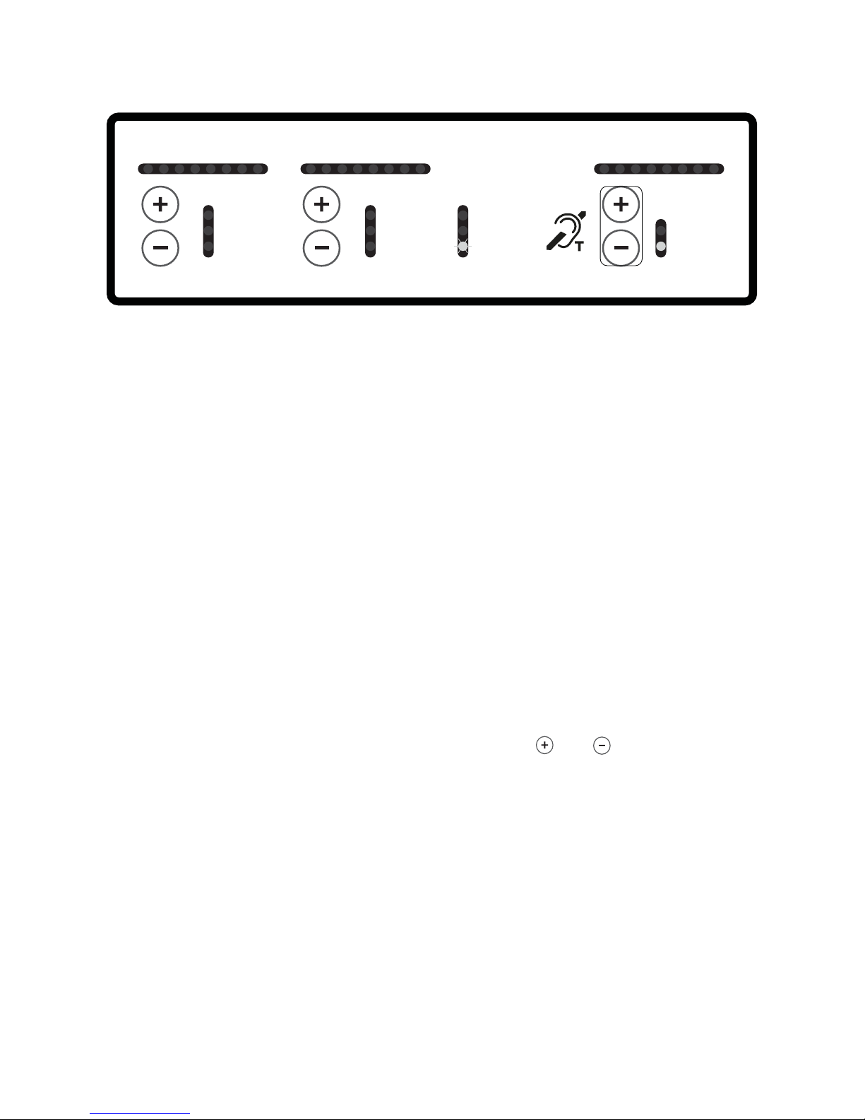
1. Conrm that the driver has been set to the SECONDARY mode
(see page 9). In this mode the driver follows the signal sent from the
primary or perimeter loop driver.
2. Connect an RJ45 cable between the expansion jack of the primary/
perimeter driver and the expansion jack on the secondary driver. Note:
If connected to a primary driver the driver outputs are 90 degrees out
of phase (for a phased array).
3. Nothing should be connected to the LINE or MIC input jacks on the
back of the secondary driver, and the input controls are not used on
the secondary driver apart from the drive level.
4. To enter adjustment mode push the DRIVE ( + and - ) buttons
simultaneously until the status light begins to ash on and o.
5. If setting up a phased array bring the current level up until the
DRIVE output lights from primary and secondary driver match, after
releasing the controls. Note: there are 8 button pushes between each
output light. In the phased array you want the same signal level in the
centre of the secondary loop as you have in the primary.
CLIP
CLIP
MICLINEDRIVE
PERIMETER
2.5 5 7.5 10
contacta HLD9
CLIP
ACTIVE
PHTM
CLIP
ACTIVE
LOW SIG
STATUS
POWER
MICLINEDRIVE
PERIMETER
PRIMARY
SECONDARY
2.5 5 7.5 10
contacta HLD9
Secondary Driver Setup
*
*
Assumes unit is properly connected and loop has continuity.
To adjust drive when you have selected your mode press
DRIVE + and - together. The status LED will ash.
• Press DRIVE + to increase level.
• Press DRIVE - to reduce level.
Press DRIVE + and - together when adjustment complete
Page 12
12
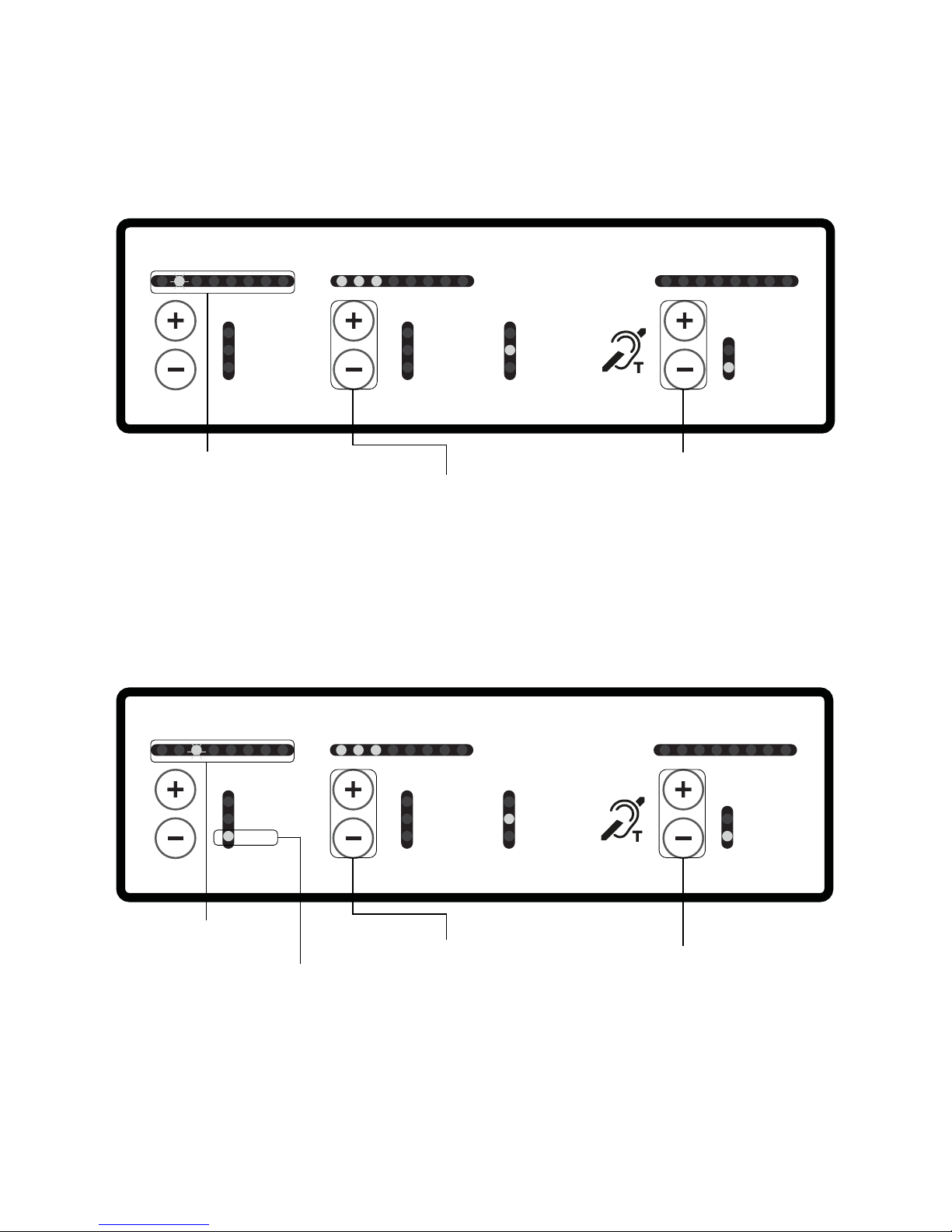
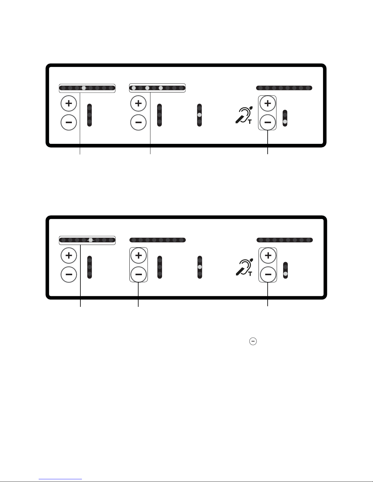
High Frequency Compensation (PAGE 2)
PAGE 2 settings are for the high frequency compensation which
is required to compensate for loss of high frequencies due to the
presence of metal within the proximity of the loop.
CLIP
ACTIVE
PHTM
CLIP
ACTIVE
LOW SIG
STATUS
POWER
MICLIN
ED
RIVE
PERIMETER
PRIMARY
SECONDARY
2.5 5 7.5 10
contacta HLD9
PAGE 2 is identied by
LED 2 ashing
Adjustments can be made by
pressing the LINE + or - buttons.
There are 6dB of HF compensation
adjustment possible
When you are ready to move
onto the next PAGE press the
DRIVE + button
Microphone Phantom Power Selection (PAGE 3)
PAGE 3 settings are for the microphone phantom power selection.
CLIP
ACTIVE
PHTM
CLIP
ACTIVE
LOW SIG
STATUS
POWER
MICLIN
ED
RIVE
PERIMETER
PRIMARY
SECONDARY
2.5 5 7.5 10
contacta HLD9
PAGE 3 is identied by
LED 3 ashing
This LED indicates
that phantom
power is on
Pressing the LINE + button turns
the phantom power on, pressing
the LINE- button turns phantom
power o
When you are ready to move
onto the next PAGE press the
DRIVE + button
Page 13
13
Firmware Revision Indication (PAGE 4)
THIS MODE IS DISPLAY ONLY: NO SETUP CAN BE CHANGED.
CLIP
ACTIVE
PHTM
CLIP
ACTIVE
LOW SIG
STATUS
POWER
MICLIN
ED
RIVE
PERIMETER
PRIMARY
SECONDARY
2.5 5 7.5 10
contacta HLD9
PAGE 4 is identied by
LED 4 ashing
PAGE 4 rmware
revision indication
When you are ready to move
onto the next PAGE press the
DRIVE + button
Restore to Factory Settings (PAGE 5)
PAGE 5 is for restoring settings.
CLIP
ACTIVE
PHTM
CLIP
ACTIVE
LOW SIG
STATUS
POWER
MICLIN
ED
RIVE
PERIMETER
PRIMARY
SECONDARY
2.5 5 7.5 10
contacta HLD9
PAGE 5 is identied
by LED 5 ashing
Press the LINE + and LINE -
button simultaneously
To go back to PAGE 1
press the DRIVE + button
To exit Engineers mode press the DRIVE - button.
CLIP
ACTIVE
PHTM
CLIP
ACTIVE
LOW SIG
STATUS
POWER
MICLINEDRIVE
PERIMETER
PRIMARY
SECONDARY
2.5 5 7.5 10
contacta HLD9
Page 14
14
Troubleshooting
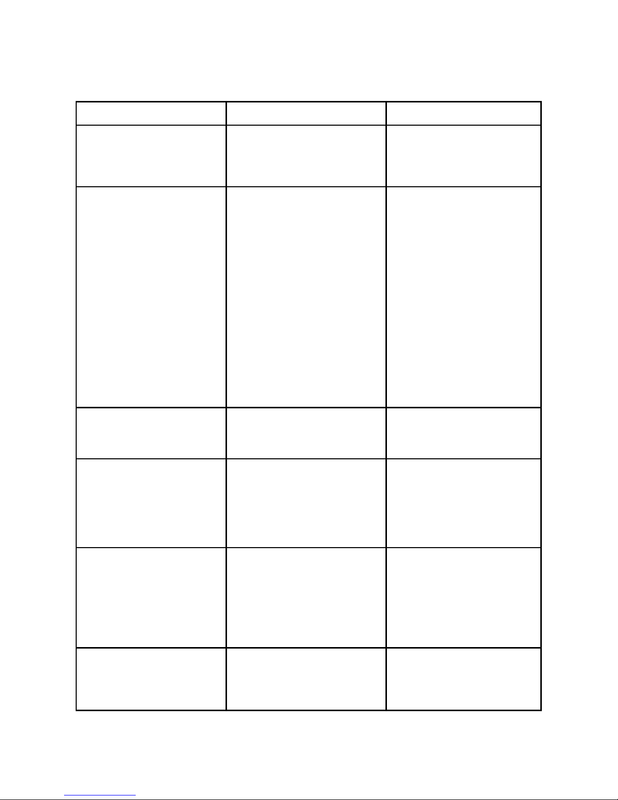
Symptom Possible Fault Action
I’ve adjusted the HF comp
and see no change.
1) The driver is working close
to maximum output so there is
not enough headroom for the
HF comp to make a dierence.
1) Check loop characteristics.
If response OK at 1 amp, the
headroom is inadequate.
I start the driver and
immediately the status light
turns on.
I start the driver and test
sequence starts, but after
it’s done, the status light
turns on.
I’ve connected the loop and
the driver doesn’t work, the
status light comes on.
My driver has been working
well for a couple weeks and
now the status light is on.
1)Loop shorted or open, too
small or too large.
2) Internal self-test failure.
1) Check loop and
connections, try known good
loop.
2) Check loop DC resistance
with an ohm meter:
0.33 ohms minimum.
The power light doesn’t
come on.
1) Mains power absent.
2) Internal failure.
1) Check mains power.
2) Seek assistance.
I can’t get my driver out of
adjustment mode.
1) Button presses not
coinciding.
2) Internal failure.
1) Press both buttons together
to exit mode.
2) As a last resort, cycle
power o/on. New settings
should have been saved.
Interference (buzzing/
whistling/hissing) is heard
through induction loop.
1) Bad input signals.
2) Internal failure.
1) Power o driver and
conrm that interference isn’t
from external origin.
2) Disconnect input signals.
If sound disappears, check
inputs.
My driver is very hot. 1) Large amount of mains hum
present on input.
2) Internal failure.
1) Check input signal source.
2) Incorrect driver being used.
Page 15
15
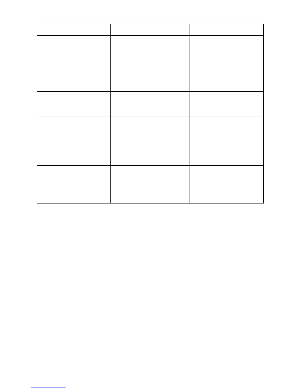
Symptom Possible Fault Action
No signal on the line input. 1) No input signal connected.
2) HLD in slave mode.
3) Equipment failure.
1) Check “active” light: if unlit
check source, if lit, adjust
level.
2) HLD must be in
PERIMETER or PRIMARY.
3) Seek assistance.
The low signal light is on. 1) The HLD is having to use very
high gain to process the input
signal.
1) Increase the input signal
level at source, reduce the
HLD input level setting.
The Drive level indicate
current is owing but I hear
nothing in the loop.
1) Shorted feeder cable
(unlikely).
2) Loop listener not working or
being used away from loop.
1) Check feeder cable,
although the HLD will usually
refuse to tune to shorted
feeder.
2) Check listener and
location.
The sound is very distorted. 1) Input level has been turned
up too high for signal level at
input jack.
2) Input signal is distorted.
1) Reduce input level setting.
2) Check signal source.
HLD = Hearing Loop Driver.
If no action is successful please seek assistance from
your distributor or a Contacta installer.
Page 16

16
Mains input
Voltage: 100V-120V /200V-240V AC (Universal auto switching)
Frequency: 50Hz-60Hz
Power: 200W
Connection: IEC
Audio Inputs
Input 1
(Microphone) Balanced XLR with switchable phantom power or ¼” TRS jack for electret
microphone with 12VDC power via 680Ω load
Adjustment range: O, then to maximum in 50x 1dB increments
Input 2
(Line) Balanced XLR or ¼” TRS jack (TRS gives galvanic isolation) input
Adjustment range: O, then to maximum in 50x 1dB increments
Loop output
Loop connection 4-pole speakON connector
Adjustment range
O, then too maximum in 63 1dB increments
Loop drive current
10A RMS compliance current @ 1Khz sine wave (loop dependant)
Loop drive voltage
36V RMS compliance voltage (loop dependant)
Loop current frequency response
100 Hz – 5kHz (±3dB) (loop dependant)
Distortion
Better than -51dB, inputs at nominal level
Expansion
Contacta interconnect Input or output to or from additional Contacta products with 90º phase
shift selectable
Status
Volt-free relay contacts SPCO
Feature
External monitor & control Contacta communications processor interface
Displays
Microphone level 8 level bar graph with peak hold, 6dB steps
Line level 8 level bar graph with peak hold, 6dB steps
Output drive level 8 level bar graph with peak hold, 0.6A steps
Other indications LEDs for all setup and status indications
Dimensions
Height – 2.48” (2U 19” rack mount)
Width – 7.87” (19” half rack)
Depth – 10.47”
Weight 3.8lbs
Construction/Finish
Front & Rear: Mild Steel / Top & Bottom: Aluminium Powder Coated Black
Continual improvement policy
Contacta has a policy of continual improvement for its products. This means that designs and
specications are subject to change without notice.
Technical Specication
Page 17

17
We oer a 5 year warranty* for our large area loop drivers. For our other products there is a 1
year warranty** that applies. The warranty will begin from dispatch date from our
warehouse.
Exceptions
This warranty will not cover products that have been misused, tampered with or are faulty as a
result of standard wear and tear, or careless handling. Any water damage will void the warranty
and cosmetic damage will not be covered. Cable, stickers & batteries are not included within the
warranty policy.
Returns
Our products can be returned up to 30 days from the receipt of goods. Products for return must
be within the original packaging, in unchanged condition. Bespoke and made to order products
are non-refundable.
Contact us using [email protected] if you’d like to request to return a product. Please
state the date of purchase, invoice number and your reason for return. On receipt of returned
items we will issue you a credit note for the cost of the product. Please note, we do not cover the
original cost of shipping or shipping back to us.
Faulty Goods
If you have a faulty product, please email us at [email protected].
We will work with you to resolve the problem remotely, using the standard test procedure contained in our Troubleshooting documents and other methods. If a manufacturing fault is conrmed we will arrange for the shipping back to us at our cost.
In the instance that we receive a faulty product we will either repair and return the product to you
or a credit note will be provided (the product must be in a reasonable condition according to the
terms).
If a product is returned as faulty but we cannot detect an issue, you may be charged a troubleshoot fee and you will be liable for the cost of shipping. Goods that arrive in a damaged condition must be reported to us immediately.
*Exceptions apply.
**2 year warranty for export distributors.
Warranty
Page 18
18
EMC
• BS EN 55103-1: 2009 (EMC emissions)
• BS EN 55103-2: 2009 (EMC immunity)
• FCC class “B” EMC (emissions)
This product has been designed and tested to comply with the following North American and
Canadian standards:
• UL 60065: 2015 8th edition
• CAN/CSA C22.2 No. 60065:2016 2nd Edition
• IEC 60065: 2014 8th Edition
• EN 60065: 2014 8th edition
This device complies with Part 15 of the FCC Rules. Operation is subject to the following two
conditions: (1) this device may not cause harmful interference, and (2) this device must accept any
interference received, including interference that may cause undesired operation.
CAUTION: Changes or modications not expressly approved by Contacta Systems LTD or an
authorised partner could void the user’s authority to operate the equipment.
Correct disposal of this product
This marking indicates that this product should not be disposed with other household waste
throughout the EU. To prevent possible harm to the environment or human health from
uncontrolled waste disposal and to conserve material resources, this product should be recycled
responsibly. To dispose of your product, please use your local return and collection systems or
contact the retailer where the product was purchased.
Standards
Page 19

19
Page 20
20
Local dealer:
UK & ROW
+44 (0) 1732 223900
US & Canada
+1 616 392 3400
Contacta Systems Ltd.
Oice 13, Dana Trading Estate
Transfesa Road
Paddock Wood, Tonbridge
TN12 6UT
www.contacta.co.uk
 Loading...