

Contact PSC-301 Owner's Manual
CONTACT
Model
PSC-301
OWNER'S MANUAL
18 channel CB Transceiver
Professional Quality And Performance Standards
Advanced Circuitry With PLL Synthesis
Manufactured Exclusively for
Peter Shalley Communications
554 Pacific Highway
Killara 2071
Australia
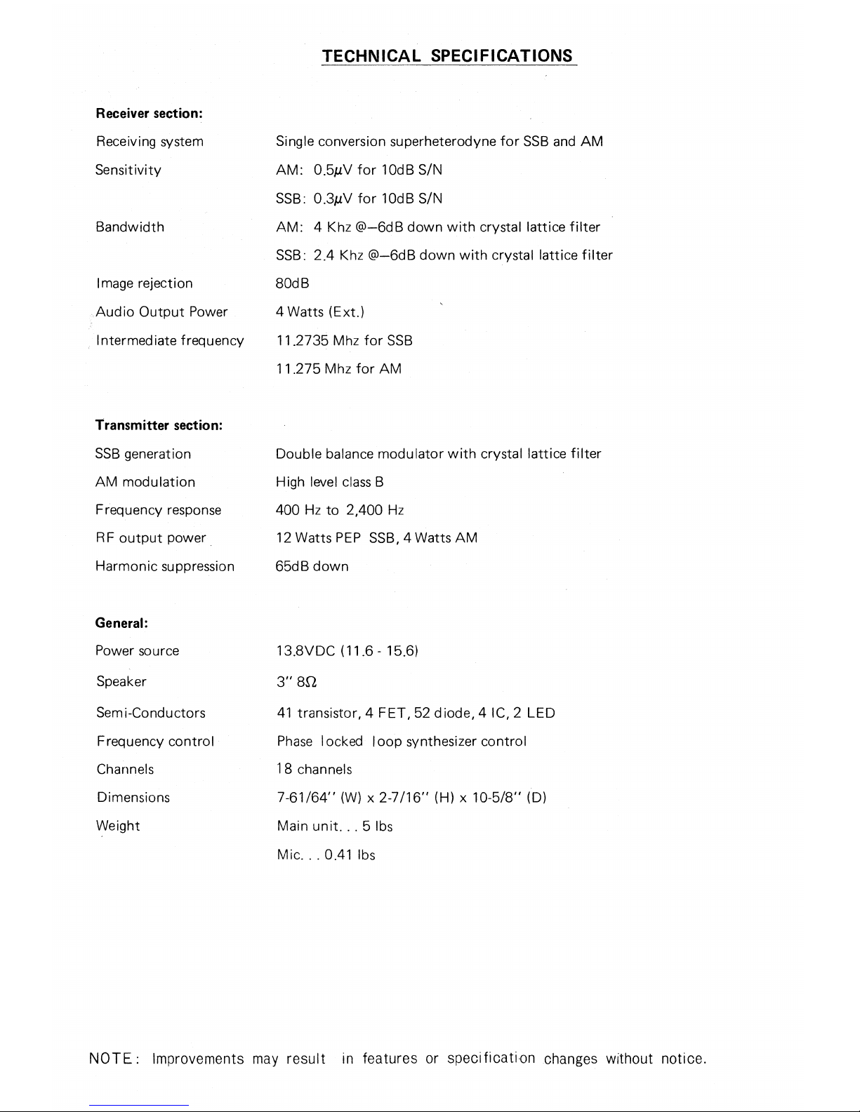
TECHNICAL SPECIFICATIONS
Receiver section:
Receiving system
Single conversion superheterodyne for SSB and AM
Sensitivity
AM: 0.51/V for 10dB S/N
SSB: 0.31,/V for 10dB S/N
Bandwidth
AM: 4 Khz @-6dB down with crystal lattice filter
SSB: 2.4 Khz @-6dB down with crystal lattice filter
Image rejection
80dB
Audio Output Power
4 Watts (Ext.)
Intermediate frequency
11.2735 Mhz for SSB
11.275 Mhz for AM
Transmitter section:
SSB generation
Double balance modulator with crystal lattice filter
AM modulation
High level class B
Frequency response
400 Hz to 2,400 Hz
RF output power
12 Watts PEP SSB, 4 Watts AM
Harmonic suppression
65dB down
General:
Power source
13.8VDC (11.6 - 15.6)
Speaker
3" 82
Semi-Conductors
41 transistor, 4 FET, 52 diode, 4 IC, 2 LED
Frequency control
Phase locked loop synthesizer control
Channels
18 channels
Dimensions
7-61/64" (W) x 2-
7
/16" (H) x 10-5/8" (D)
Weight
Main unit... 5 lbs
Mic. . 0.41 lbs
NOTE: Improvements may result in features or specification changes without notice.
GENERAL INSTRUCTIONS
Your model Contact is an all solid-state AM/SSB transceiver for 11 metre 27 Mhz Citizen Band use. It uses a
frequency synthesizing circuit to provide Phase Locked Loop controlled transmit and receive operation on all
18 channels. You can use your PSC-301 transceiver on any one of the 18 channels in the conventional AM mode,
plus the same 18 channels in either the Upper Single Sideband mode or Lower Single Sideband mode.
This flexibility not only doubles the effective number of channels from 18 to 36, but SSB also increases the
effective range of communication because all the power is concentrated in one sideband to provide 100
percent talk-power. Single Sideband reception also adds advantages in sensitivity and selectivity, plus lower
signal-to-noise. This of course also contributes to an increase in operating range.
The PSC-301 has been carefully designed for ease of operation.You can select AM,Upper Sideband or Lower
Sideband with the simple push of a button. Transmission is simple too just press the microphone button.
Ordinarily an SSB signal will reach farther and be heard more clearly than an equivalent AM signal. SSB
reception on the selected sideband is simple too....you just adjust the clarifier Control for fine tuning of the
received voice transmission.
We've added all the other most wanted features for optimum communication - RF Gain Control, Squelch,
Noise Blanker, full-time Automatic Noise Limiter to combat ignition noise and S-RF-PA level meter.
This transceiver is designed to operate from a normal 12 volt DC supply (positive or negative ground system).
LICENSING REQUIREMENTS AND APPLICATION PROCEDURES
You may not use your Citizens Band transmitter without an authorization from the post & telecommunications depar-
tment. Application for such authorization is made by filling out and mailing form RB1 3. - (Attached Citizens Band -
License Application).
VOL.-}MIC GAIN RF GAIN
SQUELCH CLARIFIER
1:36-1:1 0 0 000=
PA %)
)
1
NB
PA
AM LSB USB
CONTACT
MODEL PSC-301
POWER
ANTENNA
0
SPEAKER
PA EXT
13.8 V
MADE IN JAPAN
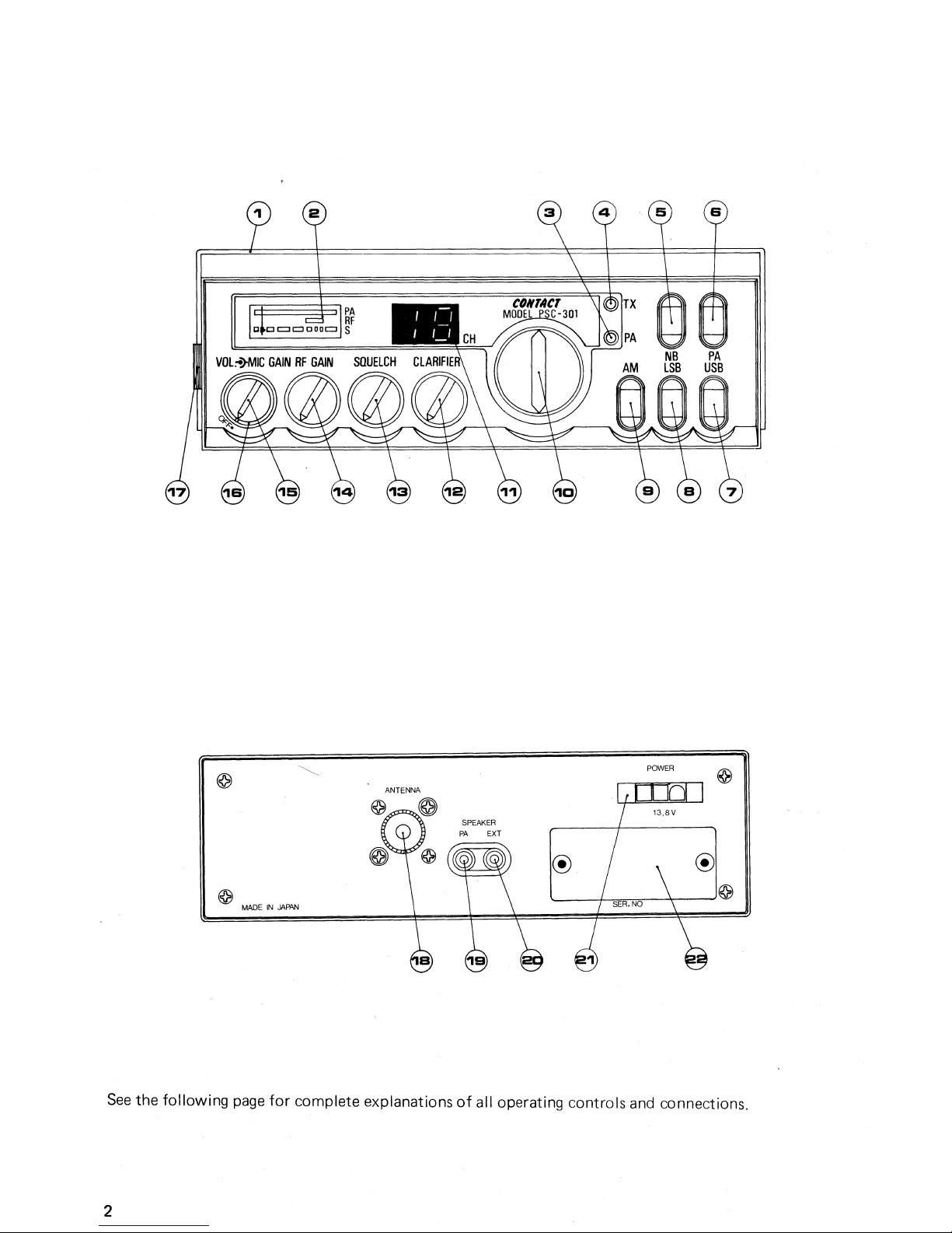
See the following page for complete explanations of all operating controls and connections.
2
14.
RF gain control
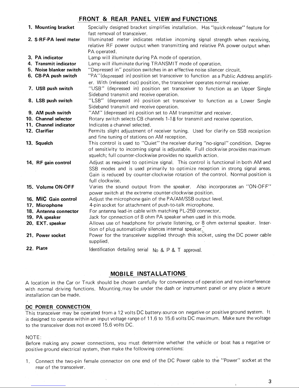
FRONT & REAR PANEL VIEW and FUNCTIONS
Specially designed bracket simplifies installation. Has "quick-release" feature for
fast removal of transceiver.
Illuminated meter indicates relative incoming signal strength when receiving,
relative RF power output when transmitting and relative PA power output when
PA operated.
Lamp will illuminate during PA mode of operation.
Lamp will illuminate during TRANSMIT mode of operation.
"Depressed in" position switches in an effective noise silencer circuit.
"PA"(depressed in) position set transceiver to function as a Public Address amplifi-
er. With (released out) position, the transceiver operates normal receiver.
"USB" (depressed in) position set transceiver to function as an Upper Single
Sideband transmit and receive operation.
"LSB" (depressed in) position set transceiver to function as a Lower Single
Sideband transmit and receive operation.
"AM" (depressed in) position set to AM transmitter and receiver.
Rotary switch selects CB channels 1-18 for transmit and receive operation.
Indicates a channel selected.
Permits slight adjustment of receiver tuning. Used for clarify on SSB receiption
and fine tuning of stations on AM reception.
This control is used to "Quiet" the receiver during "no-signal" condition. Degree
of sensitivity to incoming signal is adjustable. Full clockwise provides maximum
squelch; full counter-clockwise provides no squelch action.
Adjust as required to optimize signal. This control is functional in both AM and
SSB modes and is used primarily to optimize reception in strong signal areas.
Gain is reduced by counter-clockwise rotation of the control. Normal position is
full clockwise.
Varies the sound output from the speaker. Also incorporates an "ON-OFF"
power switch at the extreme counter-clockwise position.
Adjust the microphone gain of the PA/AM/SSB output level.
4-pin socket for attachment of push-to-talk microphone.
For antenna lead-in cable with matching PL-259 connector.
Jack for connection of 8 ohm PA speaker when used in this mode.
Allows use of headphone for private listening, or 8 ohm external speaker. Insertion of plug automatically silences internal speaker.:
Power for the transceiver supplied through this socket, using the DC power cable
supplied.
Identification detailing serial No &
P &
T approval.
15.
Volume ON-OFF
16.
MIC Gain control
17.
Microphone
18.
Antenna connector
19.
PA speaker
20.
EXT. speaker
21.
Power socket
22.
Plate
1.
Mounting bracket
2.
S-RF-PA level meter
3.
PA indicator
4.
Transmit indicator
5.
Noise blanker switch
6.
CB-PA push switch
7.
USB push switch
8.
LSB push switch
9.
AM push switch
10.
Channel selector
11.
Channel indicator
12.
Clarifier
13.
Squelch
MOBILE INSTALLATIONS
A location in the Car or Truck should be chosen carefully for convenience of operation and non-interference
with normal driving functions. Mounting,may be under the dash or instrument panel or any place a secure
installation can be made.
DC POWER CONNECTION
This transceiver may be operated from a 12 volts DC battery-source on negative or positive ground system. It
is designed to operate within an input voltage range of 11.6 to 15.6 volts DC maximum. Make sure the voltage
to the transceiver does not exceed 15.6 volts DC.
NOTE:
Before making any power connections, you must determine whether the vehicle or boat has a negative or
positive ground electrical system, then make the following connections:
1. Connect the two-pin female connector on one end of the DC Power cable to the "Power" socket at the
rear of the transceiver.
 Loading...