

Page 1
=
=
input thresshold Dig.input
protection degree (DIN 40050)
LO < 3,5V / HI > 5,5V
5
IP 20
=
=
CONTA-ELECTRONICS
=====
=====GSM controllable I
GSM controllable I////O module
==========
GSM controllable IGSM controllable I
Electrical specifications
Electrical specifications
Electrical specificationsElectrical specifications
=
=
Order Info rmation
Order Info rmation
Order Info rmation Order Info rmation
type
cat. no.
Weight
Input / O utput Data
Input / O utput Data
Input / O utput DataInput / O utput Data
8 multifunctional analog/dig. inputs
resolution / accuracy (V / I / RTD)
input resistance (0..10V)
input resistance ( 0(4)..20mA)
reference resistance (RTD)
input current (Dig.input (10-30VDC))
UI throughput speed
2 analog outputs
load resistance / current per channel
resolution / conversion error
4 relay outputs
rated / inrush current (ohmic load)
max. power rating
life span @ 23°C and ohmic loa d
max. switching frequency
contact material / test voltage
GSM Data
GSM Data
GSM DataGSM Data
Frequency (MHz)
Sensitivity
Transmit power
Antenna
General Da ta
General Da ta
General Da taGeneral Da ta
module power supply
module current (max)
operating / storage temperature
CE marking
conductor cross section / strip length
mounting / installation position
module size LxWxH (TS 35 / direct)
insulating material / flammability c lass
installation guidelines
SMS-MULTI-IO.dab.xls 07-10-2010
O module
O moduleO module
* of measured value
10mV / ±(10mV+0,3%*); 20uA / ±(20uA+0,4%*); NI1000: 0,1°C / ±2,5°C or PT 100(0): 0,1°C / ±2,5°C
resistor type: plug-in (Rt), sensor dependant ± 0,1% (5k11 for Ni/Pt100(0) -40..+120°C)(resistors not in cluded)
min. @10V: 46uA / typ. @24V: 2,6mA / max. @30V: 3,9mA (the resistor plug-in socket must be empty)
===== = = = = = = = = =
Quick Start Guide
Quick Start Guide
Quick Start GuideQuick Start Guide
=
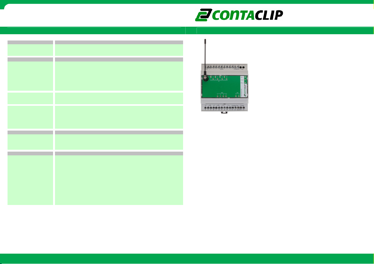
SMS-MULTI-IO
16039.2
285gr
0..10V / 0(4)..20mA / RTD / 24VDC
resistor type: fixed, 220 kOhm (the resistor plug-in socket mus t be empty)
resistor type: plug-in (Ri), 50 Ohm ± 0,1%. (resistor not included)
500ms
0…10V DC
> 1kOhm / < 10mA
10mV / ± (30mV + 0,5%*)
2 x NO contact, 2x CO contact, 250V~
8A / 12A
Electrical: at rated / 2A load: 1 x 10
EMC Directive 2004/108/EC, according requirements of EN 55011 and EN 61326-1
6 min-1 at rated current, 1200 min-1 at no load
Class 4 (2W@850/900 MHz), Class 1 (1W@1800/1900 MHz)
Low Voltage Directive (LVD) 2006/95/EC, according requirements of EN 50178
R&TTE 1999/5/EC according requirements ETSI EN 301-511 V9.0.2
0,2 - 2,5 mm² screw clamp connection / 6mm
Housing: noryl. Terminals: polyamid 6.6 V 0 / UL94-V0
for mounting-, wiring- and installation i nstructions, see Manual
2000VA
/ 4 x 10⁵ cycles. Mechanical: 30 x 106 cycles
AgNi 0,15 / 4kV
850/900/1800/1900
–106 dBm (typical)
50 Ohm impedance, SMA connector
20..28V DC
275 mA DC
-20°C…+50°C / -20°C…+70°C
DIN-rail TS35 or direct mounting / any
88 x 95 x 60 / 58 mm
=
Features:
Features:
Features:Features:
• 8 multi-functional analog/digital inputs: 0..10V,
0(4)..20mA, RTD (eg. Ni1000, PT1000, PT100), 24VDC
• 2 Analog outputs: 0...10V DC
• 4 relay outputs 2x NO contact, 2x CO contact 250V/8A
• LED status indication for all I/Os (except analog inputs)
• SMS status report for all I/Os
• SMS control for all outputs
• SMS notification on status change at inputs
• SMS notification on power up and power loss
• Easy to use PC configuration program
=
=
=
The SMS-MULTI-IO is a compact remote telemetry and
control system.
The various I/Os are monitored and controlled by SMS
communication through the GSM network.
The SMS-MULTI-IO can also be integrated into a modbus
driven application.
Every defined input status change (digital) or reached level
(analog) sends a SMS notification to a selected group of
users. The outputs are set by simply sending an SMS to the
SMS-MULTI-IO.
I/Os are defined by an easy to use PC configuration
program.
=
SMS
SMS----MULTI
MULTI----IO
SMSSMS
MULTIMULTI
IO=
IOIO
SMS-MULTI-IO quick start guide r ev1 .fl_EN.doc
Further information: www.conta-clip.com Cat. No.: 95120.4
Further information: www.conta-clip.com
Page 2
CONTA-ELECTRONICS
=====
=====GSM controllable I
GSM controllable I////O module
==========
GSM controllable IGSM controllable I
No
Note
te
NoNo
tete
=
This document is a quick start guide. For further details the complete manual can be
downloaded at:
http://www.conta-clip.com/en/service/
=
Placing the SIM card
Placing the SIM card
Placing the SIM cardPlacing the SIM card
KEEP ESD PRECAUTIONS IN MIND WHEN OPENING THE MODULE!
To open the module set the antenna at a right angle to the front of the module. Then lift the
lid with a small flat screwdriver.
Gently remove the LED PCB by lifting it from its headers.
Place a SIM card into the SIM card holder on the inside of the module. When a SIM card with
PIN code is inserted the PIN code must be entered in the configuration interface.
Replace the LED PCB and lid.
Connect the module to the 24VDC power supply.
During power up the ‘RUN’ LED should stop blinking and the ‘COM’ LED should light up after
10 seconds. The module is now ready for use.
=
Configure and connectin
Configure and connecting the module
Configure and connectinConfigure and connectin
Download and install the configuration interface:
http://www.conta-clip.com/en/service/
Connect the module with the supplied communication cable to an USB port on a PC. Connect
the opposite end to the module.
Start the configuration program and it will connect to the module. The module is now ready
for configuration.
The wiring configuration for I/O and power is shown at the top of the module.
Led status
Led status
Led statusLed status
The Led ‘Run’ indicates module activity: Flash = searching for modem
ON = power ON and modem detected
OFF = no power / no CPU activity
The Led ‘Com’ indicates network activity: green ON = connected to GSM network
green Flash = roaming GSM network
green OFF = no connected to GSM network
The Led ‘Busy’ indicates modem activity: ON = modem currently busy
O module
O moduleO module
g the module
g the moduleg the module
===== = = = = = = = = =
Default message structure
Default message structure
Default message structureDefault message structure
n = channel number
x = digital: 0= off, 1= on, 2= don’t change, 3= toggle
analog: xxxx & yyyy = 0000 to 1000 (0 to 10,00VDC)
Get status of ALL IOs:
Get status of ALL IOs: SMS: RALL
Get status of ALL IOs:Get status of ALL IOs:
Answer: ‘read DO1=x, DO2=x, DO3=x, DO4=x’
‘read UI1=xxx, UI2=xxx, ….… UI8=xxx’
‘read AO1=xxx, AO2=xxx’
Write multiple DOs:
Write multiple DOs: SMS: WMDO
Write multiple DOs:Write multiple DOs:
(Digital Outputs) Answer: ‘status DO1=x, DO2=x, DO3=x, DO4=x’
Write single DO:
Write single DO: SMS: WDO
Write single DO:Write single DO:
Answer: ‘status DOn=x‘
Read multiple
Read multiple DOs:
Read multiple Read multiple
Answer: ‘read DO1=x, DO2=x, DO3=x, DO4=x‘
Read single DO:
Read single DO: SMS: RDO
Read single DO:Read single DO:
Answer: ‘read DOn=x‘
Read multiple UIs:
Read multiple UIs: SMS: RMUI
Read multiple UIs:Read multiple UIs:
(Universal Inputs) Answer (digital): ’read UI1=x, UI2=x, …. UI8=x’
(analog): ‘read UI1=xxxx, UI2=xxxx, …. UI8=xxxx’
Read single UI:
Read single UI: SMS: RUI
Read single UI:Read single UI:
Answer (digital): ‘read UIn=x’
(analog): ‘read UIn=xxxx’
Write multiple AOs:
Write multiple AOs: SMS: WMAO
Write multiple AOs:Write multiple AOs:
(Analog Outputs) Answer: ‘status AO1=xxxx, AO2=yyyy‘
Write single AO:
Write single AO: SMS: WAO
Write single AO:Write single AO:
Answer: ‘status Aon=xxxx‘
Read multiple AOs:
Read multiple AOs: SMS: RMAO
Read multiple AOs:Read multiple AOs:
Answer: ‘read AO1=xxxx, AO2=xxxx‘
Read single AO:
Read single AO: SMS: RAO
Read single AO:Read single AO:
Answer: ‘read AOn=xxxx‘
Module Reset:
Module Reset: SMS: WRESET
Module Reset:Module Reset:
NOTE:
Further information: www.conta-clip.com Cat. No.: 95120.4
NOTE:
DOs:
DOs:DOs:
DOn /UIn/AOn can be replaced by a user given name with the configuration interface.
Correct sending and receiving of data depends on the network quality of your provider.=
SMS: RMDO
Answer: Powercycle message
Further information: www.conta-clip.com
RALL
RALLRALL
WMDOxxxx
WMDOWMDO
WDOnx
WDOWDO
RMDO
RMDORMDO
RDOn
RDORDO
RMUI
RMUIRMUI
RUIn
RUIRUI
WMAOxxxxyyyy
WMAOWMAO
WAOnxxxx
WAOWAO
RMAO
RMAORMAO
RAOn
RAORAO
WRESET
WRESETWRESET
SMS
SMS----MULTI
MULTI----IO
SMSSMS
MULTIMULTI
IO=
IOIO
 Loading...