

Page 1
www.conta-clip.com
CONTA-CONNECT
www.conta-clip.com
Weitere Informationen | Further Information:
TYP RK 50...240
TYPE RK 50...240
Anwendung | Handling
Anschluss von Massivleitern und flexiblen Leitern mit/ohne Aderendhülsen |
Connecting rigid wires or flexible wires with/without wire-end ferrules
Besonderheit | Special Feature
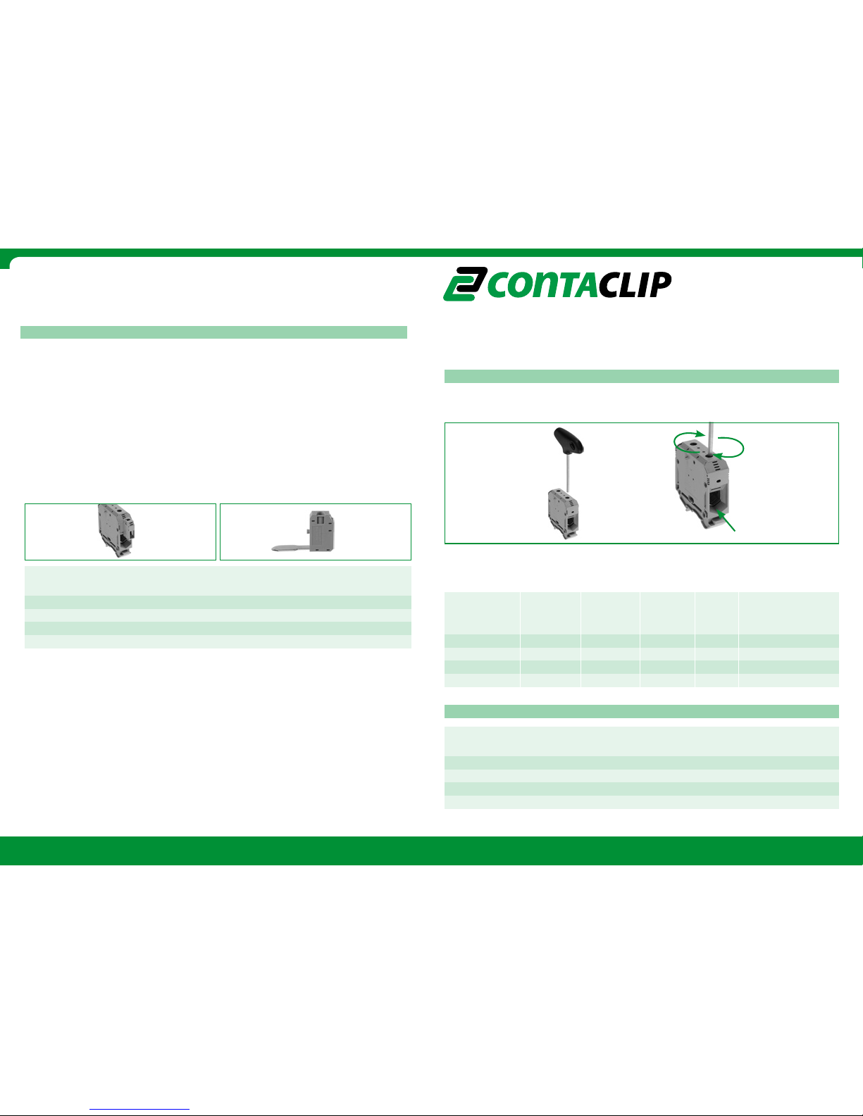
Bedienungsanleitung für das
Schraub-Anschluss-System |
Operating instructions for
Screw Connection System
Anschlussvermögen und Anzugsdrehmomente für Klemmschrauben |
Connection data and tightening torque of terminal screws
Reihenklemme 1 Leitung 2 Leitungen Bandleiter Gewinde Anzugsdrehmoment
Type
1 wire/mm
2
2 wire/mm2 Ribbon/mm Thread Torque
flexibel/starr
|
flexibel/starr|
Breite/Länge
M| NM|
flexible/rigid flexible/rigid
width/length
M NM
RK 50 2
5-50/16-50 16-25/10-25 11,8x5 M 6 6-8
RK 95 25-95/25-95 25-35/25-35 16x6 M 8 8-12
RK 150 35-150/35-150 35-50/25-50 20x8 M 10 14-20
RK 240 70-240/50-240 50-95/35-95 20x12 M 10 14-20
Messabgriffsklemmen MAG ermöglichen einen Spannungsabgriff an Reihenklemmen größeren
Querschnittes durch Leiter kleineren Querschnittes von 0,2 bis 10 mm2. MAG Anschlusselemente
werden oberhalb der Hauptleitereinführung in die jeweilige Reihenklemme eingebracht und
kontaktieren über die Anschlussschraube der Hauptreihenklemme die Stromschiene. Diese sichere
technische Lösung vereinfacht die Verdrahtung erheblich.
Reihenklemme Innen-Sechskant-Schlüssel Best.-Nr.:
Terminal block Allan key Cat.-No.:
RK 50 ISKS 5 2818.0
RK 95 ISKS 6 2772.0
RK 150 ISKS 8 2773.0
RK 240 ISKS 8 2773.0
Betätigungswerkzeug | Operating tool
Weitere Alternat ehmen Sie bitte unserem Hauptkatalog CONTA-CONNECT! | You will find further alternatives in our main catalogue CONTA-CONNECT!
Reihenklemme Messabgriffklemme MAG Best.-Nr.:
Terminal block Pick up terminal MAG Cat.-No.:
RK 50 MAG 50 1121.2
RK 95 MAG 95 1123.2
RK 150 MAG 150/240 1125.2
RK 240 MAG 150/240 1125.2
Best.-Nr.: 95103.0 Weitere Informationen | Further Information:
Messabgriffsklemmen MAG | Measurement Pick-Up Terminals MAG
MAG measurement pick-up terminals allow the voltage to be picked up on terminal blocks with larger
cross sections by conductors with smaller cross sections from 0.2 to 10 mm2. MAG connection elements
are inserted into the respective terminal block above the mains lead-in and make contact with the
contact rail through the connection screw of the main terminal block. This safe technical solution
simplifies wiring considerably.
Leitereinführung/
Wire introduction
Sicherheitshinweis Schraub-Anschluss-Reihenklemmen RK | ATEX
D
ie Reihenklemmen sind geeignet zum Einsatz in Gehäusen zur Verwendung in Bereichen mit brennbaren Gasen und
brennbarem Staub. Für brennbare Gase müssen diese Gehäuse den Anforderungen gemäß EN 60079-0 und EN 60079-7
entsprechen. Für brennbaren Staub müssen diese Gehäuse den Anforderungen gemäß EN 60079-31 entsprechen. Die
angewendeten Normen müssen dem Stand der Technik entsprechen. Bei Mischung mit anderen Baureihen und -größen
und Verwendung von Zubehör ist auf die Einhaltung der erforderlichen Luft- und Kriechstrecken zu achten. Die maximal
zulässige Temperatur an den Isolierteilen beträgt 85°C. Die Umgebungstemperatur Ta darf 40°C nicht übersteigen!
ACHTUNG: Die Bewertung der Luft- und Kriechstrecken kann zu einer Reduzierung der Nennspannung führen.
Im Rahmen des Inverkehrbringens ist diese Bewertung nach den Komformitätsverfahren der Richtlinie 2014/34/Eu für
die zutreffende Kategorie durchzuführen.
Notes on safety: Screw connection system RK | ATEX
The terminal blocks are suitable for installing in housings for use in applications subject to combustible gases or
combustible dust. For use in applications subject to combustible gases, these housings must comply with EN 60079-0
and EN 60079-7. For use in applications subject to combustible dust, these housings must comply with EN 60079-31.
The applied Standards have to reflect the state-of-the-art of technology. Ensure that the required clearance and creepage
distances are adhered to when combining with other product ranges and sizes or with accessories. The maximum
permitted temperature for insulated com-ponents is 85°C. The ambient temperature Ta must not exceed 40°C!
CAUTION: Evaluation of the clearance and creepage distances can lead to a reduction of the rated voltage. Under the
aspect of legislation covering the sale of such products, this evaluation is to be performed in accordance with the
conformity assessment procedures for the applicable category as specified in the directive 2014/34/Eu.
Page 2
www.conta-clip.com
CONTA-CONNECT
Bedienungsanleitung für das Schraub-Anschluss-System
|
Operating instructions for Screw Connection System
Weitere Informationen | Further Information:
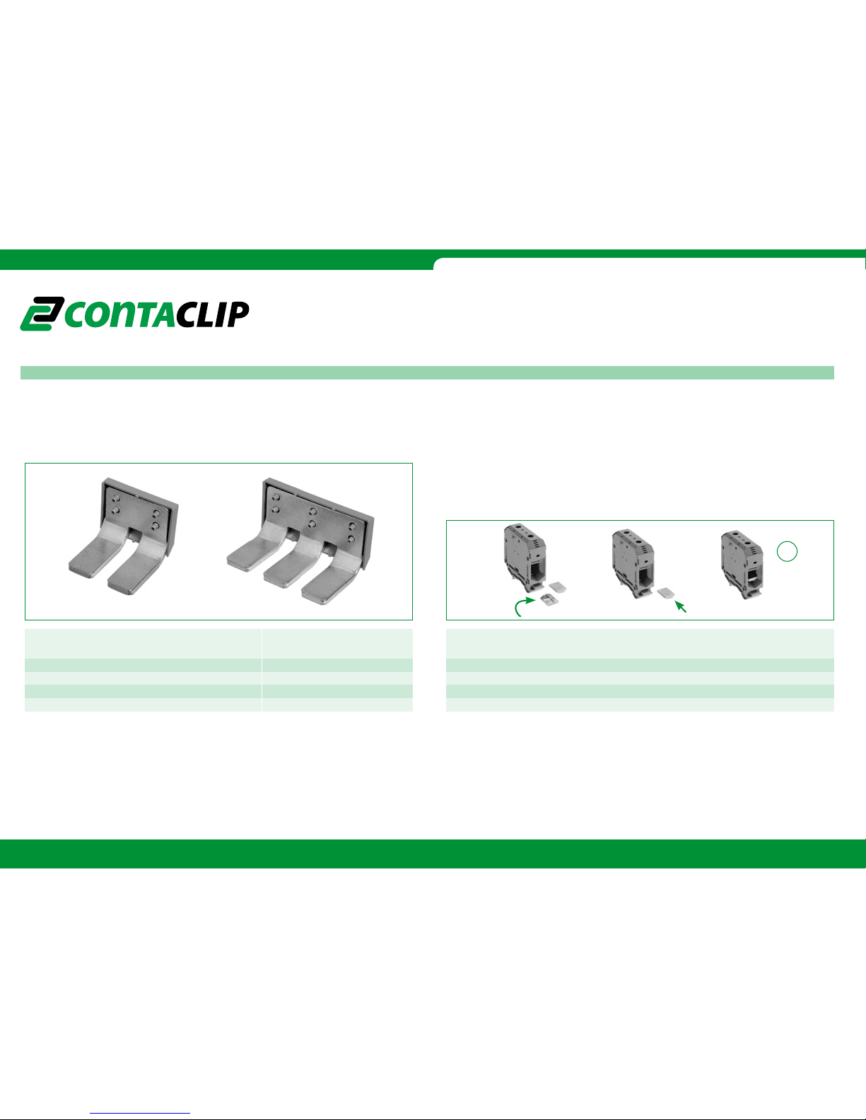
Anschluss von Bandleitern | Connection of ribbon conductors
Achtung! Bei Verwendung der AQI reduziert sich der Anschlussquerschnitt um eine Stufe.
|
Attention! When using AQI the rated cross section is reduced by one section.
Einsatz von Außenquerverbindungen isoliert AQI |
Using of outer cross-connection, insulated AQI
Querverbindungsmöglichkeiten | Cross-connection option
Hinweis für den Einsatz von CONTA-CLIP Reihenklemmen in Ex e Anwendungen.
Beim Einsatz von Querverbindungen entnehmen Sie bitte unserer Homepage die ange passten
Strom- und Spannungswerte.
Tip for the use of CONTA-CLIP terminals in Ex e applications.
Please see on our website for the suitable voltages for the use
of cross connections.
Reihenklemme 2-polig AQI Best.-Nr.: 3-polig AQI Best.-Nr.:
Terminal block 2-poles AQI Cat.-No.: 3-poles AQI Cat.-No.:
RK 50 AQI 2/50 2763.2 AQI 3/50 2764.2
RK 95 AQI 2/95 2765.2 AQI 3/95 2766.2
RK 150 AQI 2/150 2767.2 AQI 3/150 2768.2
RK 240 AQI 2/240 2769.2 AQI 3/240 2770.2
Achtung! Bei anzuschließenden Bandleitern ist es notwendig Einlegeplatten in den Zugbügel einzubringen. Die Einlegeplatte EP gleicht in dem Zugbügel (Anschlusskäfig) die V-förmige Geometrie aus.
Hierdurch wird auch bei Bandleitern ein sicherer und zuverlässiger Anschluss gewährleistet.
Attention! When connecting ribbon conductors, it is necessary to put insertion plates in the strain-relief-
clamps. The insertion plate EP compensate for the V-form geometry in the strain-relief-clamps (terminal
cage). This also guarantees a safe and dependable connection of the ribbon conductor.
Reihenklemme Einlegeprofil EP Best.-Nr.:
Terminal block Insertion plate EP Cat.-No.:
RK 50 EP 50 2274.0
RK 95 EP 95 2275.0
RK 150 EP 150 2277.0
RK 240 EP 240 2360.2
4
 Loading...