

Page 1
GSM-PRO
Instruction Manual
Instruction Manual
Instruction ManualInstruction Manual
feb 2014 rev7.0
Page 2

Contents
Contents
ContentsContents
GSM-PRO
1 DESCRIPTION ................................................................................................................ 4
1.1 Summary .................................................................................................................................. 4
1.2 Safety instructions .................................................................................................................... 4
1.3 General note ............................................................................................................................. 4
2 SOFTWARE .................................................................................................................... 5
2.1 System requirements ................................................................................................................ 5
2.2 Software installation ................................................................................................................. 5
3 MODULE ....................................................................................................................... 6
3.1 Place the SIM card .................................................................................................................... 6
3.2 Connect the antenna ................................................................................................................ 7
3.3 Connect to power .................................................................................................................... 7
3.4 Connect to PC .......................................................................................................................... 8
3.5 LED description ........................................................................................................................ 8
3.5.1 Module status indication ....................................................................................................8
3.5.2 IO indication ......................................................................................................................8
4 CONFIGURATION ......................................................................................................... 9
4.1 Connect to the GSM-PRO ......................................................................................................... 9
4.2 Synchronize ............................................................................................................................ 10
4.2.1 Upload changes to the module ........................................................................................10
4.2.2 Download settings from module ......................................................................................10
4.2.3 Reset module to default ....................................................................................................10
4.2.4 Synchronize date/time with PC.........................................................................................10
4.2.5 Restart device ...................................................................................................................11
4.2.6 Connect to module ..........................................................................................................11
4.3 Diagnostics ............................................................................................................................. 12
4.3.1 Signal quality ...................................................................................................................12
4.4 Phonebook ............................................................................................................................. 13
4.4.1 Add contacts ....................................................................................................................13
4.4.2 Delete contacts.................................................................................................................14
4.4.3 Import / Export phonebook ..............................................................................................15
4.5 Settings .................................................................................................................................. 16
4.5.1 Main settings ....................................................................................................................16
4.5.2 Periodical message ...........................................................................................................16
4.5.3 Power cycle message ........................................................................................................16
4.5.4 Power down message ......................................................................................................16
Page 3

GSM-PRO
4.5.5 Active users ......................................................................................................................16
4.5.6 Import / Export settings ....................................................................................................17
5 ADVANCED SETTINGS ................................................................................................ 18
5.1 Update ................................................................................................................................... 19
5.1.1 Manual firmware updates ................................................................................................19
5.1.2 OTA firmware update .......................................................................................................19
5.1.3 OTA configuration ............................................................................................................19
5.1.4 Send update information..................................................................................................20
5.2 Network ................................................................................................................................. 20
5.2.1 Allow data usage ..............................................................................................................20
5.2.2 Roaming...........................................................................................................................21
5.2.3 APN settings .....................................................................................................................21
5.2.4 OTA Time synchronisation ................................................................................................21
5.2.5 App ..................................................................................................................................21
5.2.6 Portal ...............................................................................................................................21
5.3 SMTP ...................................................................................................................................... 21
5.3.1 SMTP settings ...................................................................................................................22
5.3.2 SMTP test .........................................................................................................................22
5.4 Log 22
5.4.1 Event log ..........................................................................................................................23
5.4.2 AI log ...............................................................................................................................23
5.4.3 IO operating hours counter ..............................................................................................24
5.4.3.1 Request digital output counter .................................................................................24
5.4.3.2 Request digital input counter ...................................................................................24
5.4.3.3 Reset digital output counter .....................................................................................24
5.4.3.4 Reset digital input counter .......................................................................................24
5.4.4 Monitor input changes during restart ...............................................................................24
5.5 SIM 25
5.5.1 Change SIM pin ...............................................................................................................25
5.5.2 Insert PUK code ................................................................................................................25
5.6 COM port ............................................................................................................................... 25
6 I/O CONFIGURATION AND MESSAGING ..................................................................... 26
6.1 Digital Outputs ....................................................................................................................... 26
6.1.1 Configuration ...................................................................................................................26
6.1.2 Select users ......................................................................................................................27
6.1.3 Messaging ........................................................................................................................27
6.1.3.1 Number ID ...............................................................................................................27
6.1.3.2 User defined instructions ..........................................................................................27
6.1.3.3 Writing to multiple digital outputs ...........................................................................27
6.1.3.4 Writing to a single digital output ..............................................................................27
6.1.4 Using the one-shot function .............................................................................................28
6.1.5 Reading from multiple digital outputs ..............................................................................28
6.1.6 Reading from a single digital output .................................................................................28
Page 4

GSM-PRO
6.1.7 React on RING ..................................................................................................................28
6.1.8 Link DO to DI ...................................................................................................................28
6.1.9 Activate when GSM connection is lost ..............................................................................28
6.1.10 Preserve status on startup ............................................................................................29
6.1.11 Wiring example ............................................................................................................29
6.2 Universal Inputs ...................................................................................................................... 30
6.2.1 Reading from multiple universal inputs ............................................................................30
6.2.2 Select receivers .................................................................................................................30
6.2.3 Confirmation sequence ....................................................................................................30
6.3 Analog inputs ......................................................................................................................... 31
6.3.1 Configuration ...................................................................................................................31
6.3.2 Reading from an analog input ..........................................................................................32
6.3.3 Wiring example ................................................................................................................32
6.4 Digital Inputs .......................................................................................................................... 33
6.4.1 Configuration ...................................................................................................................33
6.4.2 Reading from a digital input .............................................................................................33
6.4.3 Connect to V out ..............................................................................................................34
6.4.4 Wiring example ................................................................................................................34
6.5 Read all IO statuses ................................................................................................................. 35
6.6 Link multiple GSM-PRO’s ........................................................................................................ 35
7 OTHER MESSAGES ...................................................................................................... 36
7.1 Module reset .......................................................................................................................... 36
7.2 Stop messaging ...................................................................................................................... 36
7.3 Show all SMS commands ....................................................................................................... 36
8 ADDITIONAL HARDWARE ............................................................................................ 37
8.1 External antenna ..................................................................................................................... 37
8.2 Programming cable ................................................................................................................ 37
9 ADDITIONAL SOFTWARE ............................................................................................ 38
9.1 GSM-PRO App ........................................................................................................................ 38
9.2 GSM-PRO Portal...................................................................................................................... 38
10 TROUBLESHOOTING ................................................................................................... 40
10.1 Cannot connect to the PC, no module found ......................................................................... 40
10.2 No connection to GSM network ............................................................................................. 40
10.3 The module doesn’t send any messages ................................................................................. 40
10.4 The module doesn’t start ........................................................................................................ 40
10.5 Diagnosis ................................................................................................................................ 41
10.5.1 USB ..............................................................................................................................41
10.5.2 OTA .............................................................................................................................41
Page 5

GSM-PRO
10.5.2.1
Port forwarding ...................................................................................................41
11 APPENDIX: SMS COMMANDS..................................................................................... 42
12 APPENDIX: DIAGNOSTIC COMMANDS ....................................................................... 44
13 APPENDIX: SIGNAL STRENGTHS ................................................................................. 45
14 APPENDIX: TECHNICAL SPECIFICATIONS .................................................................... 46
Page 6

1111 DES
DESCRIP
DESDES
1.1
1.1 Summary
1.11.1
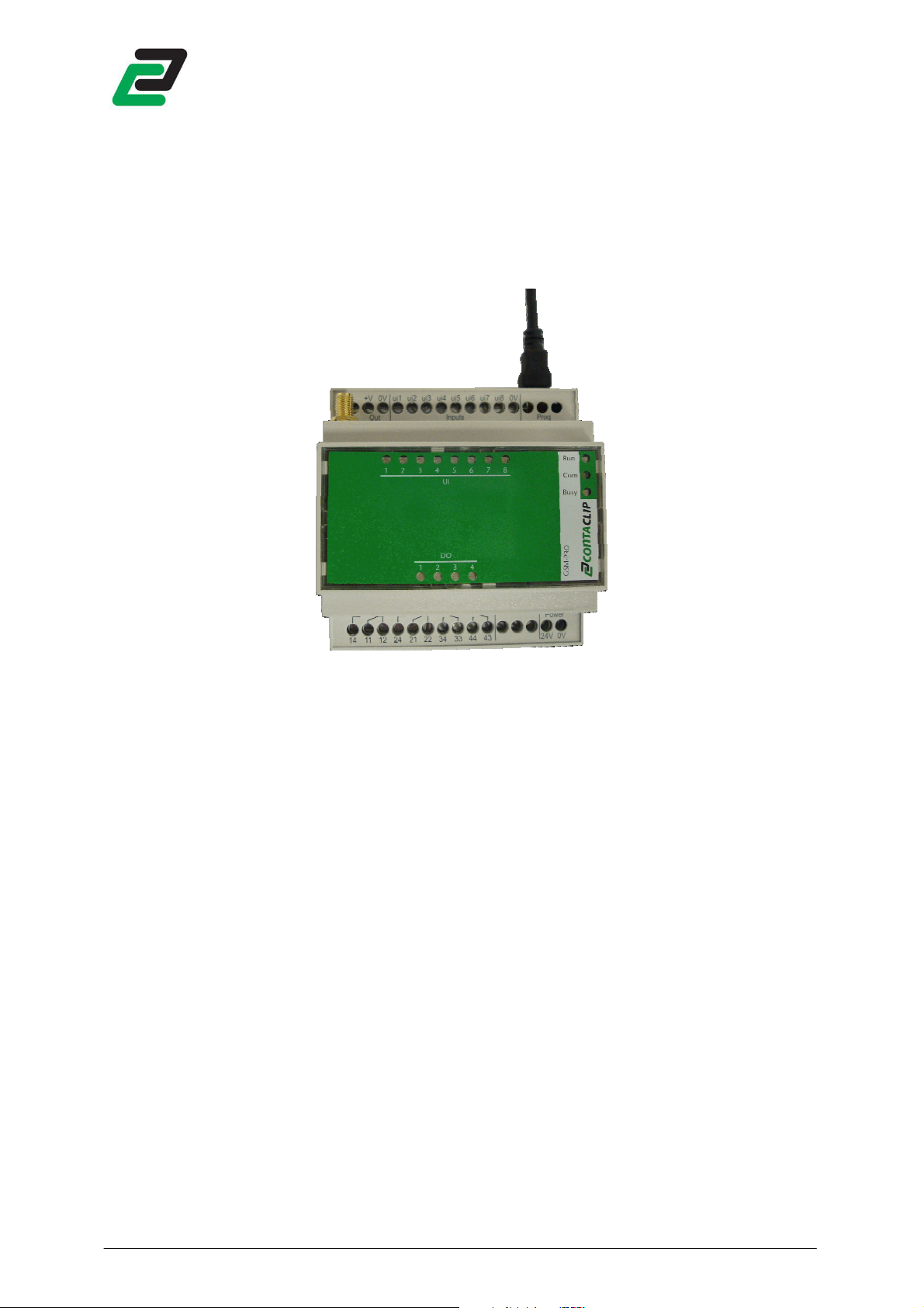
The GSM-PRO is a compact remote control and messaging system. All IOs are monitored by SMS and
email and controlled by SMS communication through the GSM network.
The module can be configured with the GSM-PRO PC-software. Each IO can be modified by userdefined parameter names and messages. A selected group of users can be chosen from the
phonebook to control the module, or only receive messages.
GSM-PRO features:
• 4 Digital Outputs (DO), relay CO contact 250V/5A
• 8 Universal Inputs (UI) which can be set by software as:
On each defined input status change (rising or falling flank for digital inputs or reached level for
analog inputs) the module sends a pre- or user-defined message to the selected group of users.
The outputs can be set when a selected user sends a pre- or user-defined SMS to the GSM-PRO.
The GSM-PRO sends a periodical message on user defined times. On power loss the module holds
enough power to send SMS messages to all selected GSM users (NO email). It also sends messages
when coming back from a power reset.
1.2
1.2 Safety instructions
1.21.2
GSM-PRO
CRIPTION
CRIPCRIP
Summary
SummarySummary
Safety instructions
Safety instructionsSafety instructions
TION
TIONTION
- Analog Input (AI), 0..10V
- Digital Input (DI)
• This device is NOT suitable for monitoring sensible or time critical processes. Power
interruption or GSM network failures do not guarantee flawless monitoring.
• Keep ESD precautions in mind when opening the module.
• This module can require a GSM data connection. For information about costs ask your GSM
service provider.
1.3
1.3 General note
General note
1.31.3
General noteGeneral note
This manual applies to firmware and interface version 2.0.0 or higher. Some functions are not
available in older versions.
NOTE:
Firmware version 1.6.2 or lower is not compatible with interface version 2.0.0 or higher.
Firmware version 2.0.0 or higher is not compatible with interface version 1.5.2 or lower.
Please contact Conta-Clip when an older revision is needed.
- 4 -
Page 7
GSM-PRO
2222 SSSSOFTWAR
Download the latest GSM-PRO interface software at:
http://www.conta-clip.com/en/service/
On start up the interface software checks if there is a new interface available and, when a module is
connected, a new firmware version is available. To manually check for updates click: Help -> check for
updates.
NOTE: checking for updates requires an internet connection.
2.1
2.1 System requirement
2.12.1
The following requirements are needed to run and use the software properly:
2.2
2.2 Software installat
2.22.2
As the program needs to install hardware drivers make sure you have administrator rights.
Run the GSM-PRO_setup.exe to install the application. The setup wizard will guide you through the
rest of the setup process.
When starting the interface for the first time it will prompt if you want to keep informed on updates
by email. This function can be repeated in the advanced settings update tab (see 5.1).
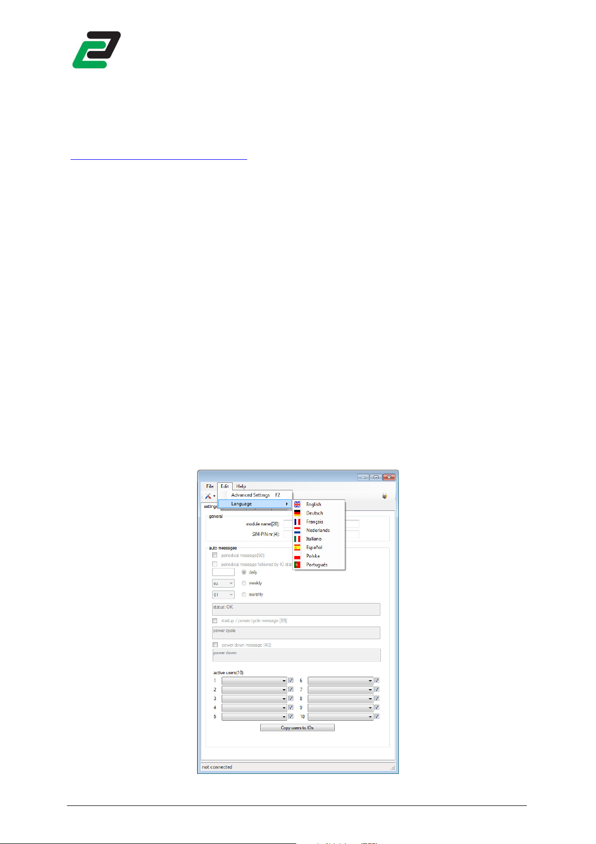
After starting the interface set the language by: Edit -> Language. The chosen language is saved and
recalled at start up.
OFTWAREEEE
OFTWAROFTWAR
System requirementssss
System requirementSystem requirement
• Windows XP sp3, Vista, 7, 8
• Minimal 1024 x 768 pixels screen resolution
• 100MB Hard disc capacity available
• 256MB RAM
• USB port
Software installation
Software installatSoftware installat
ion
ionion
- 5 -
Page 8
3333 MODULE
MODULE
MODULEMODULE
3.1
3.1 Place the SIM card
3.13.1
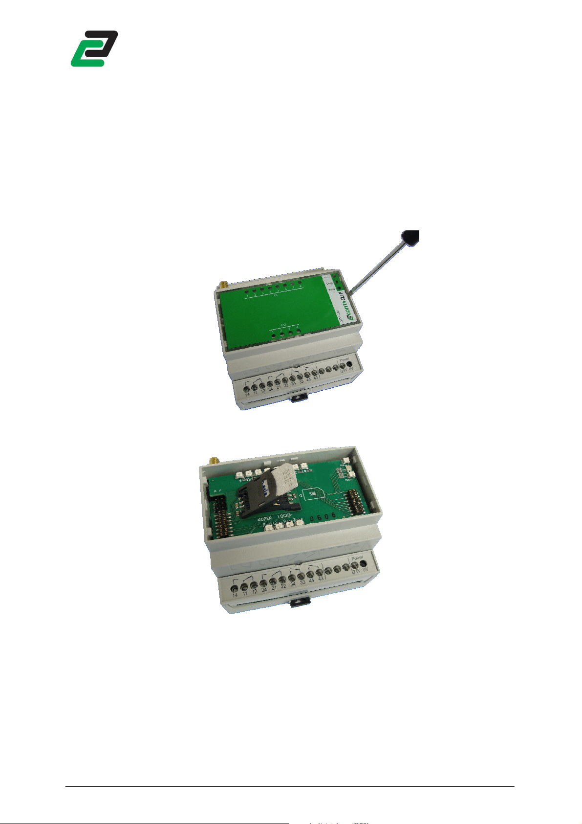
NOTE: Keep ESD precautions in mind when opening the module.
Place a SIM card into the SIM card holder to access the GSM network:
• Lift the lid with a small flat screwdriver.
GSM-PRO
Place the SIM card
Place the SIM cardPlace the SIM card
• Place a SIM card into the SIM card holder (image may vary).
• Replace the lid.
- 6 -
Page 9
3.2
3.2 Connect the antenna
3.23.2
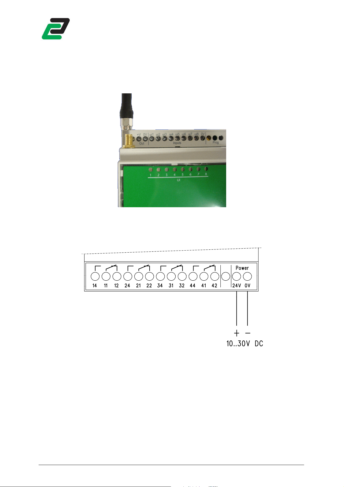
Connect the antenna on the antenna connector on top of the module.
GSM-PRO
Connect the antenna
Connect the antennaConnect the antenna
3.3
3.3 Connect to power
Connect to power
3.33.3
Connect to powerConnect to power
Connect the 24V and 0V to a 24VDC power supply (10..30VDC).
- 7 -
Page 10
3.4
3.4 CCCCoooonnec
3.43.4
Connect a USB cable (artnr. 16103.2, sold separately, please contact Conta-Clip for further
information) to the mini USB socket on the module, and the other end to a USB port on a PC.
NOTE: Make sure to install the interface software and drivers before connecting the module to a PC.
GSM-PRO
nnect to PC
t to PC
nnecnnec
t to PCt to PC
3.5
3.5 LED description
LED description
3.53.5
LED descriptionLED description
3.5.1
3.5.1 Module status indication
3.5.13.5.1
After connecting the power it takes about 10 seconds before the first Led activates.
The Led ‘Run’ indicates module activity:
The Led ‘Com’ indicates network activity:
The Led ‘Busy’ indicates module activity:
After data transfers between the PC and the module, the module performs a reset. During this time all
UI Led’s light up and all other Led’s are off.
3.5.2
3.5.2 IO indication
3.5.23.5.2
Module status indication
Module status indicationModule status indication
• Flash = starting-up (takes about 90 seconds)
• ON = ready for use (blinks every 10 seconds)
• OFF = no power
• green ON = connected to GSM network’
• green Flash = roaming GSM network
• green OFF = not connected to GSM network
• ON = module currently busy
IO indication
IO indicationIO indication
• For each Digital Output a Led lights up when the relay is activated.
• The Universal Input Led’s light up when:
- When set as digital input : the input is active (1)
- When set as analog input : a top or bottom threshold is exceeded
- 8 -
Page 11
4444 CONFIGURATION
CONFIGURATION
CONFIGURATIONCONFIGURATION
4.1
4.1 Connect to the
4.14.1
Connect 24VDC to the module and connect a USB cable between the GSM-PRO and a PC USB port.
Wait for the module to start up and run the GSM-PRO interface software.
NOTE: module start up takes about 90 seconds, after connecting to power it takes about 10 seconds
before the first Led activates.
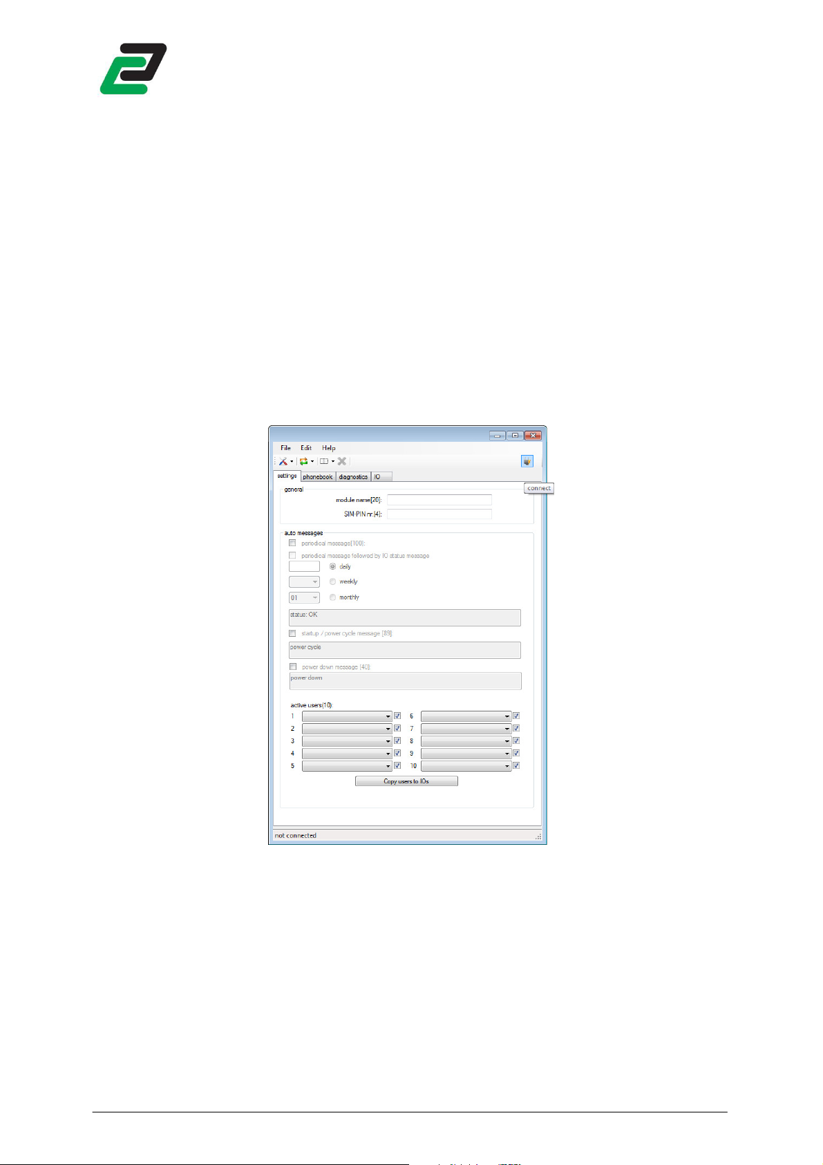
On start up the configuration software searches all available COM ports for an available GSM-PRO.
When found, the software downloads the diagnostic data and prompts to download the settings
from the device. If chosen yes, the user interface will be automatically updated.
If no module was found on start-up, click the connect button in the upper right corner to search for
the module:
GSM-PRO
Connect to the GSM
Connect to the Connect to the
GSM----PRO
PRO
GSMGSM
PROPRO
If the module is found the text ‘connected’ at the bottom left side will appear.
- 9 -
Page 12
GSM-PRO
4.2
4.2 Synchronize
Synchronize
4.24.2
SynchronizeSynchronize
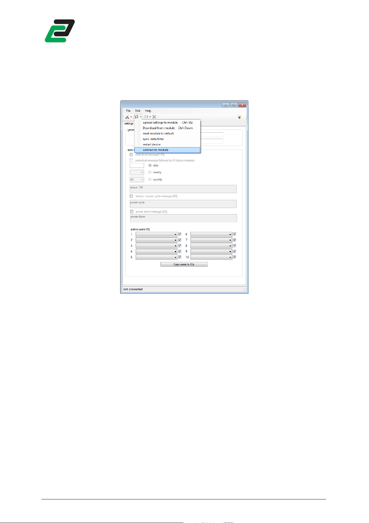
Press the synchronize button to edit the module:
4.2.1
4.2.1 Upload changes to the module
4.2.14.2.1
Upload changes to the module
Upload changes to the moduleUpload changes to the module
Upload current configuration software settings to the module.
NOTE: uploading settings to the module overwrites all settings within the module. Therefore it is
highly recommended to download the settings from the module first, before uploading any new
changes.
4.2.2
4.2.2 Download settings from module
4.2.24.2.2
Download settings from module
Download settings from moduleDownload settings from module
Download all settings from the module into the interface.
4.2.3
4.2.3 Reset module to default
4.2.34.2.3
Reset module to default
Reset module to defaultReset module to default
Restore all settings in the module back to factory default.
4.2.4
4.2.4 Synchronize date/t
4.2.44.2.4
Synchronize date/time
Synchronize date/tSynchronize date/t
ime with PC
imeime
with PC
with PCwith PC
The date and time of the module are synchronized with your PC system time.
- 10 -
Page 13

4.2.5
4.2.5 Restart device
4.2.54.2.5
GSM-PRO
Restart device
Restart deviceRestart device
Due to the internal capacity it’s not possible to quickly reset the device by powering off. Click this
button to reset the device by software.
4.2.6
4.2.6 Connect t
4.2.64.2.6
Connect to module
Connect tConnect t
o module
o moduleo module
Find a module and connect to it by USB.
- 11 -
Page 14
4.3
4.3 Diagnostics
4.34.3
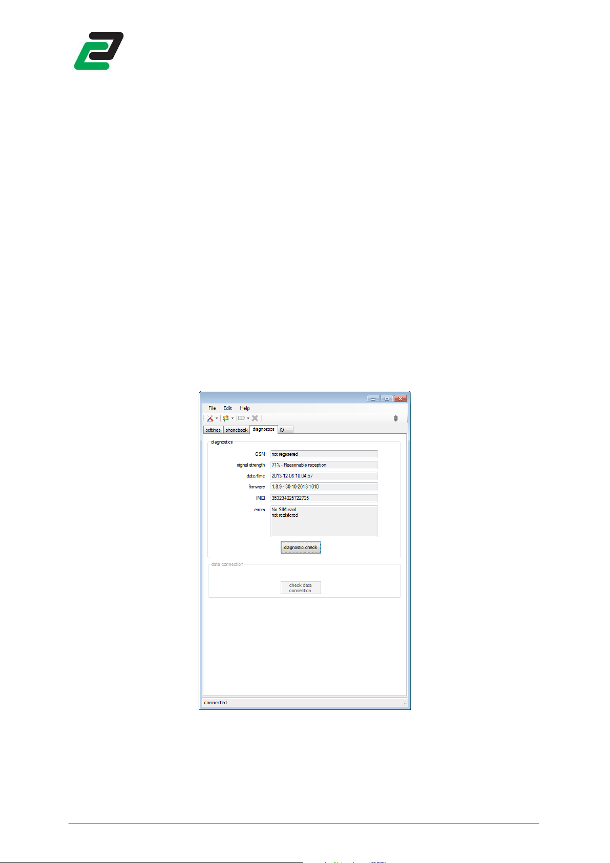
After connecting to the module the diagnostics tab is filled. This page shows:
• Registered GSM network or connection errors
• Signal strength in percentage and signal quality
• Module timestamp
• Module firmware version
• IMEI number
• Error messages:
Refresh the diagnostics tab by clicking the ‘diagnostic check’ button.
To request the diagnostics by SMS send:
Press the ‘check data connection’ button to test if a GPRS (internet) connection can be established by
the module. Check chapter 5.2. for further instructions on setting up an internet connection.
GSM-PRO
Diagnostics
DiagnosticsDiagnostics
- SIM PIN code required
- SIM PUK code required
- No SIM card
- Date / Time not set
- No user selected
- No network registration
status
status
.
statusstatus
4.3.1
4.3.1 Signal quality
4.3.14.3.1
The signal quality information is defined by the Dutch Telecom Agency according to GSM network
regulations. The full list is shown in the appendix.
To request the signal strength /and quality by SMS send:
Signal quality
Signal qualitySignal quality
- 12 -
csq
csq
csqcsq
.
Page 15
GSM-PRO
4.4
4.4 Phonebook
Phonebook
4.44.4
PhonebookPhonebook
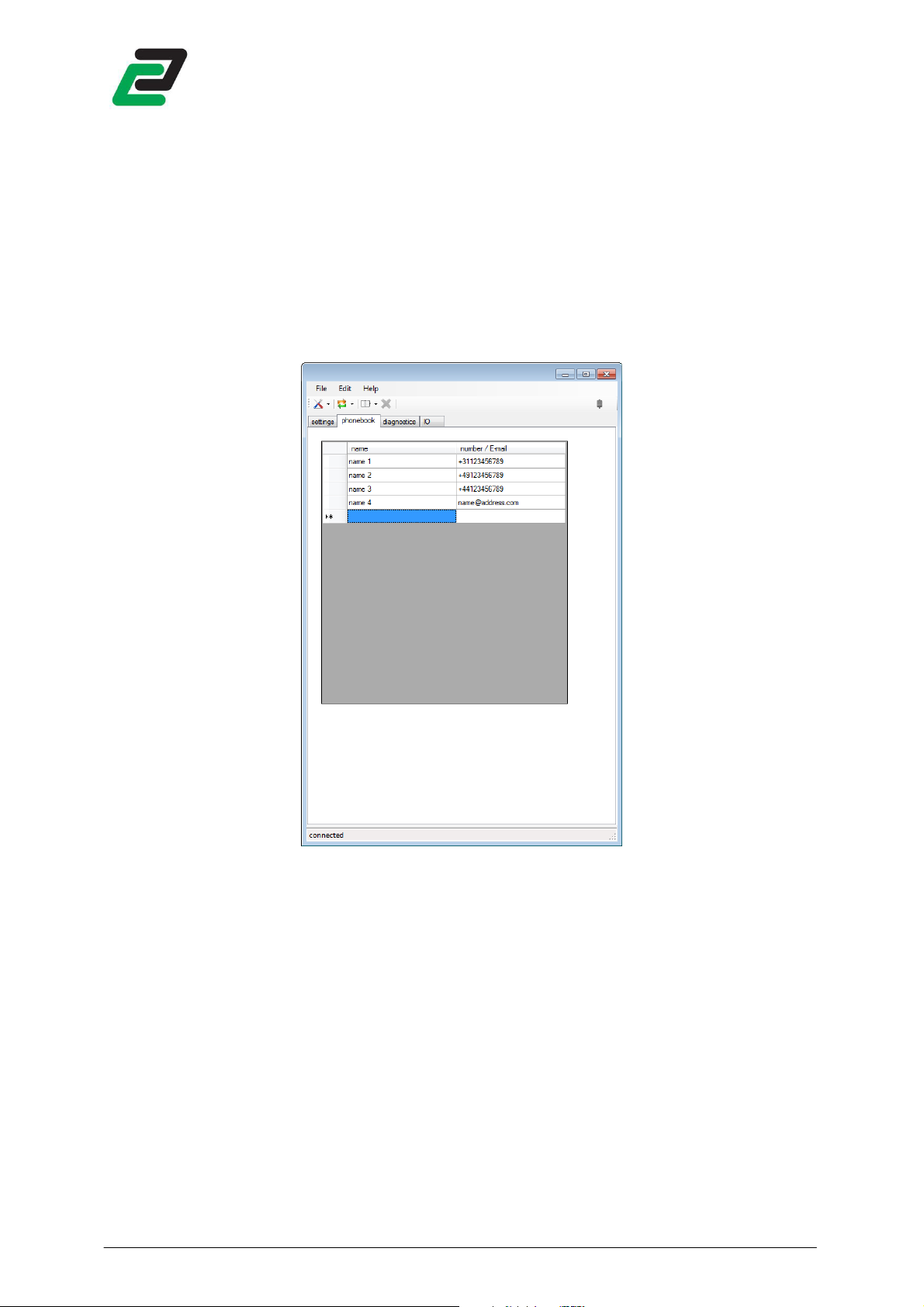
The interface software has a phonebook to list all your contacts for further usage. All actions in the
phonebook will auto save on completion.
4.4.1
4.4.1 Add contacts
4.4.14.4.1
Add contacts
Add contactsAdd contacts
To add a contact to the phonebook click on the next empty row and fill in the name and phone
number or email address.
NOTE: The phone number must be preceded by the international access code
E.g.:
• UK +44
• Germany +49
• France +33
• Netherlands +31
• Italy +39
• Spain +34
• Poland +48
• Portugal +351
- 13 -
Page 16

GSM-PRO
4.4.2
4.4.2 Delete contacts
4.4.24.4.2
Delete contacts
Delete contactsDelete contacts
To delete a contact select one or multiple rows to delete and click the delete button.
- 14 -
Page 17

4.4.3
4.4.3 Import /
4.4.34.4.3
GSM-PRO
Import / Export
Import / Import /
Export phonebook
Export Export
phonebook
phonebookphonebook
The phonebook can be exported for usage on another PC that has the interface software installed. To
export the phonebook click the ‘phonebook’ button and ‘export phonebook’. Windows prompts
‘save as’. Save the file with a given name on a preferred destination to the PC.
To import the phonebook click the ‘phonebook’ button and ‘import phonebook’. Windows prompts
to point the location of an exported *.cpf file.
- 15 -
Page 18

GSM-PRO
4.5
4.5 Settings
Settings
4.54.5
SettingsSettings
4.5.1
4.5.1 Main settings
4.5.14.5.1
Main settings
Main settingsMain settings
The main functions of the module are configured in the ‘settings’ tab:
• Module name
• SIM pin number, this is the pin number to access the SIM card. By most providers it is default
set to 0000.
4.5.2
4.5.2 Periodical message
4.5.24.5.2
Periodical message
Periodical messagePeriodical message
The GSM-PRO can send a periodical message on a user defined time:
• Daily, set the time
• Weekly, set the day and time
• Monthly, set the day of the month and time
This message can be supplemented with the actual status of all IOs.
4.5.3
4.5.3 Power cycle message
4.5.34.5.3
Power cycle message
Power cycle messagePower cycle message
The GSM-PRO can send a message on every module start up, so the users are aware of a power
recovery.
4.5.4
4.5.4 Power down message
4.5.44.5.4
Power down message
Power down messagePower down message
On power loss the module holds enough capacity to send SMS messages to the first 5 selected GSM
users.
The GSM-PRO detects a power down when the power < 8V and returns when the power > 10V.
NOTE: The module tries to send the message to all defined users in the settings tab with the
guarantee of the first 5 selected users.
4.5.5
4.5.5 Active users
4.5.54.5.5
Active users
Active usersActive users
The active users are those who have full access to the module and receive the auto messages. The
sequence of messaging is determined by the order of selected users (nr 1 to 10).
If a user only needs to access the module but doesn’t want to receive any messages uncheck the
checkbox behind the user.
Click the button ‘Copy users to UIs’ to copy the selected users from the settings tab to all UI tabs.
- 16 -
Page 19

GSM-PRO
4.5.6
4.5.6 Import /
4.5.64.5.6
Import / Export settings
Import / Import /
Export settings
Export settingsExport settings
Export the settings to preserve them for later usage after closing the user interface. To export all
settings click the ‘settings’ button and ‘export settings’. Windows prompts ‘save as’. Save the file with
a given name on a preferred destination to the PC.
To import the settings click the ‘settings’ button and ‘import settings’. Windows prompts to point the
location of an exported *.ccf file.
To print all settings click print settings and select an available printer.
- 17 -
Page 20

5555 ADVANCED SETTINGS
ADVANCED SETTINGS
ADVANCED SETTINGSADVANCED SETTINGS
Access the ‘advanced settings’ by clicking Edit->advanced settings or tapping F2.
The following functions can be configured:
• updates
• network connection
• email
• logging
• SIM card
• COM port
GSM-PRO
After completing the set-up the configuration needs to be uploaded to the module. See chapter 4.2.1
for further details.
- 18 -
Page 21

5.1
5.1 Update
5.15.1
The GSM-PRO can perform firmware updates remote(OTA) or when connected by USB to a PC.
OOOOver TTTThe AAAAir (OTA) covers remote actions where the data is transmitted over GPRS.
GSM-PRO
Update
UpdateUpdate
NOTE: To perform an OTA action the module has to be registered to a GSM data connection and data
usage has to be allowed (see section network settings)
5.1.1
5.1.1 Manual firmware updates
5.1.15.1.1
Download the latest firmware at: http://www.conta-clip.com/en/service/
After downloading, unzip the complete folder to a location on your PC. Click the firmware update
button and the software prompts to the location of the firmware. Locate the unzipped folder and
select the GSM-PRO.jar file.
During the firmware update all UI Leds on the module light up. The firmware update takes about 2
minutes. After the update the module restarts itself.
NOTE: do NOT disconnect the module or turn off the power supply during this operation.
5.1.2
5.1.2 OTA firmware update
5.1.25.1.2
To remotely update the firmware send:
it and restarts. When a firmware update is succeeded the module sends a confirmation to the sender.
To check the modules current firmware version send:
firmware version: <version number>.
To check if there is a newer firmware version available send:
name> (No) update found. Online <firmware version> local: <firmware version>.
5.1.3
5.1.3 OTA configuration
5.1.35.1.3
Manual firmware updates
Manual firmware updatesManual firmware updates
OTA firmware update
OTA firmware updateOTA firmware update
OTA configuration
OTA configurationOTA configuration
fotap
fotap
. The GSM-PRO downloads the online firmware, installs
fotapfotap
fwv
fwv
. The module answers <module name>
fwvfwv
cupd
cupd
. The module answers <module
cupdcupd
rotac
rotac
The configuration with the user interface can be performed remotely. Send:
procedure. When the command is received the module uploads the current configuration to the
- 19 -
rotacrotac
to start this
Page 22

Conta-Clip server and answers: ‘module IMEI nr: <IMEI nr> <module name> configuration file
uploaded.’
Fill the unique module International Mobile Equipment Identity (IMEI) into the user interface and
press ‘download configuration’. The user interface will be automatically updated with the settings of
the (remote) module.
After making the required changes to the configuration, press ‘upload configuration’ to upload the
new configuration onto the Conta-Clip server. Configuration files are kept on the server for 5 days.
Finally send:
configuration and resets, this will take about one minute. Finally the module answers: ‘<module
name> configuration file updated’.
The configuration file can also be requested by sending:
(e.g.
configuration file is received by the email address. Download and import the file into the interface, for
further information see chapter 4.5.6.
NOTE: to up- and download the configuration the PC has to be connected to the internet.
5.1.4
5.1.4 Send update information
5.1.45.1.4
GSM-PRO
cotac
cotac
to inform the module that the new configuration is online. It will download the
cotaccotac
ccf
ccf
directly followed by a valid email address
ccf ccf
ccf
ccf
name@conta-clip.de). When ready, the module answers with a confirmation message and the
ccfccf
Send update information
Send update informationSend update information
Send us your contact details to stay informed on any updates regarding this product.
Your details will be used for this purpose only.
5.2
5.2 Network
Network
5.25.2
NetworkNetwork
5.2.1
5.2.1 Allow data usage
5.2.15.2.1
Allow data usage
Allow data usageAllow data usage
Mark this checkbox if a data connection is required.
NOTE: Activating mobile internet can cause unexpected costs. Contact your provider for an
appropriate subscription or prepaid card.
If the internet connection is required but not allowed after configuration send an SMS:
name>,<APN username>,<APN password>
name>,<APN username>,<APN password>
name>,<APN username>,<APN password>name>,<APN username>,<APN password>
The module establishes an internet connection upon next restart. The module can now be upgraded
or configured over the air.
- 20 -
APN,<APN
APN,<APN
APN,<APN APN,<APN
Page 23

If the internet connection has to maintain after restart, this can be configured remotely.
5.2.2
5.2.2 Roaming
5.2.25.2.2
If roaming is disabled the module blocks SMS and data connections when registered to a foreign
GSM network.
NOTE: contact your GSM service provider for roaming rates to avoid unexpected high billing.
5.2.3
5.2.3 APN settings
5.2.35.2.3
To register to a GPRS connection, enter the APN (Access Point Name) settings of your GSM service
provider. If these settings are unknown to you, request them at your provider.
Before uploading them into the module the APN settings can be tested by pressing the ‘test’ button.
This tests the APN settings entered into the fields in the interface.
Remotely check the GSM data connection by sending:
the connection.
5.2.4
5.2.4 OTA
5.2.45.2.4
The module can check online if date/time is not correct, if needed the module performs a
synchronisation.
When selected this action is performed approximately every 24hours after powering up.
To synchronize date/time by SMS send:
synchronise.
The module answers: <module name> set time to <timestamp>.
NOTE: after synchronizing date/time the module automatically restarts.
5.2.5
5.2.5 App
5.2.55.2.5
GSM-PRO
Roaming
RoamingRoaming
APN settings
APN settingsAPN settings
cdc
cdc
. The module answers with the status of
cdccdc
OTA Time synchronisation
Time synchronisation
OTA OTA
Time synchronisationTime synchronisation
time
time
. The module takes the provider message timestamp to
timetime
App
AppApp
Mark the checkbox to synchronize your GSM-PRO’s events and IO status so it can be read and
controlled by an Apple iOS or Android App.
5.2.6
5.2.6 Portal
5.2.65.2.6
Mark the checkbox and fill your PC’s remote IP and port to allow the GSM-PRO to access the Portal
software.
See the GSM-PRO Portal manual for further instructions.
5.3
5.3 SMTP
5.35.3
Enter the SMTP (Simple Mail Transfer Protocol) settings for outgoing email. The SMTP is used to send
email via outgoing mail server. Insert these values only if you want the module to send emails.
Portal
PortalPortal
SMTP
SMTPSMTP
- 21 -
Page 24

GSM-PRO
5.3.1
5.3.1 SMTP settings
5.3.15.3.1
SMTP settings
SMTP settingsSMTP settings
Conta-Clip offers free usage of the SMTP server for outgoing mail of the GSM-PRO. If you want to use
the Conta-Clip SMTP server enter ‘Conta-Clip’ as the server name.
NOTE: Conta-Clip does not guarantee any uptime of this service.
If you prefer to use your own SMTP server, enter your SMTP settings. Contact your hosting service for
further details.
Make sure to insert a valid sender, this is an email address on the SMTP server. When this is not
correct some servers might not accept self-addressed email or the email might not get past spam
filters.
NOTE: SSL connected SMTP servers e.g. Hotmail / Gmail are not supported by the GSM-PRO.
5.3.2
5.3.2 SMTP test
5.3.25.3.2
SMTP test
SMTP testSMTP test
Before uploading into the module, the SMTP settings can be tested by entering an existing email
address and then pressing the ‘test’ button. This tests the APN settings entered into the fields in the
interface.
NOTE: A GSM data connection is required to test the SMTP server.
5.4
5.4 Log
Log
5.45.4
LogLog
The GSM-PRO can keep log files with a maximum size of 720 events. When a log is 90% full the
module sends a warning message to the active users. When the log is 100% full the module sends
another warning message and then it stops logging until downloaded or erased.
A full log can also be sent automatically to one selected email address. After this action the log file is
automatically erased and the module continues logging.
Each log can be viewed and erased while connected to the PC by clicking the button or remote by
sending a command.
- 22 -
Page 25

GSM-PRO
5.4.1
5.4.1 Event log
5.4.15.4.1
Event log
Event logEvent log
When this log is enabled the GSM-PRO logs the following events:
• Reached threshold limits on the AI inputs
• Rising and falling flank on the digital inputs (DI)
• Received messages
• Sent messages
• Data transmissions
• OTA updates
When connected, view this log by clicking ‘view event log’. View remote by sending:
followed by a valid email address (e.g.
evlog
evlog
name@conta-clip.de). When ready, the module answers
evlogevlog
evlog
evlog
evlogevlog
directly
with a confirmation message and the event log is received at the email address.
When connected erase the event log by clicking ‘erase event log’. Erase remote by sending:
evclr
evclr
evclrevclr
The module answers with a confirmation message.
NOTE: on heavy usage the event log is filled rapidly. It is highly recommended to choose the auto
send option when enabled.
5.4.2
5.4.2 AI
5.4.25.4.2
AI log
log
AIAI
loglog
Choose the interval for the AI log:
• 10 min (5 days)
• 15 min (7.5 days)
• 20 min (10 days)
• 30 min (15 days)
• 45 min (22.5 days)
• 60 min (30 days)
The log duration in days is based on logging 1 AI.
When connected, view this log by clicking ‘view AI log’. View remote by sending:
followed by a valid email address (e.g.
ailog
ailog
name@conta-clip.de). When ready the module answers
ailogailog
ai
ailog
log
aiai
loglog
directly
with a confirmation message and the AI log is received by the email address.
.
- 23 -
Page 26

GSM-PRO
When connected, erase the event log by clicking ‘erase AI log’. Erase remote by sending:
module answers with a confirmation message.
5.4.3
5.4.3 IO operating hours counter
5.4.35.4.3
The IO operating hours counter sums the total time the IO is in HI state. The counter can be turned
on/off each individual digital in- and output. The counted value can be added to the periodical
message and ‘RALL’(see chapter 6.5).
Counters are limited to 17500 hours.
NOTE: make sure to keep all IO’s in LO state when configuring the counters due to faults in starting
time.
5.4.3.1
5.4.3.1 Request digital output counter
5.4.3.15.4.3.1
To retrieve the counter value of an individual digital output, send:
the requested digital output. The module answers: ‘Don ON for x,xx hours’.
To retrieve the counter values of all digital outputs send:
The module answers: ‘Do1 was ON for x,xx hours, Do2 was ON for x,xx hours … Do4 was ON for x,xx
hours’,
5.4.3.2
5.4.3.2 Request digital input counter
5.4.3.25.4.3.2
To retrieve the counter value of an individual digital input, send:
the requested digital input. The module answers: ‘Din ON for x,xx hours’.
To retrieve the counter value of all digital inputs send:
The module answers: ‘Di1 was ON for x,xx hours, Di2 was ON for x,xx hours … Di8 was ON for x,xx
hours’.
IO operating hours counter
IO operating hours counterIO operating hours counter
Request digital output counter
Request digital output counterRequest digital output counter
Request digital input counter
Request digital input counterRequest digital input counter
timedo0.
timedo0.
timedo0.timedo0.
timedi0.
timedi0.
timedi0.timedi0.
time
timedo
timetime
timedi
timedin
timeditimedi
don
, where n is the number of
dodo
, where n is the number of
aiclr
aiclr
aiclraiclr
. The
5.4.3.3
5.4.3.3 Reset digital output counter
5.4.3.35.4.3.3
To reset the counter value of an individual digital output, send:
the requested digital output. The module answers: ‘erasing counter Don’.
To reset the counter values of all digital outputs, send:
counter Do1, erasing counter Do2… erasing counter Do4’.
5.4.3.4
5.4.3.4 Reset digital input counter
5.4.3.45.4.3.4
To reset the counter value of an individual digital input, send:
the requested digital input. The module answers: ‘erasing counter Din’.
To reset the counter values of all digital inputs, send:
counter Di1, erasing counter Di2… erasing counter Di4’.
5.4.4
5.4.4 Monitor input changes during restart
5.4.45.4.4
The module detects changes on the inputs while restarting. The status when is saved on restart /
power-down and will be compared on next start-up. Any changes detected are send to the
configured users.
Reset digital output counter
Reset digital output counterReset digital output counter
Reset digital input counter
Reset digital input counterReset digital input counter
Monitor input changes during restart
Monitor input changes during restartMonitor input changes during restart
clr
clrtimedo
timedo0000
clrclr
timedotimedo
clr
clrtimedi
timedi0000
clrclr
timeditimedi
clr
clrtimed
timedoooon
clrclr
timedtimed
. The module answers: ‘erasing
clr
clrtimedi
timedin
clrclr
timeditimedi
. The module answers: ‘erasing
, where n is the number of
, where n is the number of
- 24 -
Page 27

5.5
5.5 SIM
SIM
5.55.5
SIMSIM
GSM-PRO
5.5.1
5.5.1 Change SIM pin
5.5.15.5.1
Change the SIM pin code by inserting the current pin code and the new one. Click ‘change SIM pin’
to change.
5.5.2
5.5.2 Insert PUK code
5.5.25.5.2
When a wrong PIN number is given 3 times the SIM card is locked and requests the PUK code. The
diagnostics page shows this in the error messages. Insert the correct PUK and PIN code and click
‘insert PUK code’.
5.6
5.6 CCCCOM port
5.65.6
The COM port tab shows on which COM port a GSM-PRO module is found.
Change SIM pin
Change SIM pinChange SIM pin
Insert PUK code
Insert PUK codeInsert PUK code
OM port
OM portOM port
- 25 -
Page 28

6666 I/O
I/O CONFIGURATION AND ME
I/OI/O
The module responds to read and write commands. Commands are preceded by an ‘r’ for read and
‘w’ for write actions.
All SMS commands are NOT case sensitive.
6.1
6.1 Digital Output
6.16.1
6.1.1
6.1.1 Configuration
6.1.16.1.1
The GSM-PRO has 4 CO outputs. The following items can be configured with the software:
• Name, this name must be unique and cannot be used with any other input or output. Default
• After setting a digital output the module sends a confirmation message followed by the actual
• Send only the user defined text, this sends only the text defined in the message box, no
• Define your own instructions to control the output.
• Activate or toggle the output when starting a phone call with the module.
• Link DO to DI
• Activate when GSM connection lost, deactivate when GSM connection returns.
• Preserve or deactivate the status on restart or power cycle.
GSM-PRO
CONFIGURATION AND MESSAGING
CONFIGURATION AND MECONFIGURATION AND ME
Digital Outputssss
Digital OutputDigital Output
Configuration
ConfigurationConfiguration
set as DO1 to DO4.
output state. This message is sent only to the sender of the message.
module name, IO name and timestamp. See section 6.6.
SSAGING
SSAGINGSSAGING
- 26 -
Page 29

6.1.2
6.1.2 Select
6.1.26.1.2
GSM-PRO
Select users
users
Select Select
usersusers
The recipients have access to the associated digital output.
NOTE: Selected DO users do not have any rights to send other commands to the module other than
addressed to the defined output.
6.1.3
6.1.3 Messaging
6.1.36.1.3
Messaging
MessagingMessaging
It is possible to send self made instructions or use the pre-defined instructions per output or as a
group as described in the next chapters.
With these instructions an output can be activated, deactivated and activated for a given period of
time (one-shot).
6.1.3.1
6.1.3.1 Number ID
6.1.3.16.1.3.1
Number ID
Number IDNumber ID
The number ID for setting a digital output can be disabled per output. When disabled the output
responds on both SMS and incoming calls (see 6.1.3.6) from everyone.
NOTE: keep safety precautions in mind when disabling this function together with the ring function
due to unwanted incoming calls.
6.1.3.2
6.1.3.2 User defined instructions
6.1.3.26.1.3.2
Use a self made instruction to control an output. E.g. you may want to use the instruction
activate output 1, and
User defined instructions
User defined instructionsUser defined instructions
pumpoff
to deactivate.
pumpon
In this way the multiple outputs can also be controlled by configuring the same instruction for
another output.
It is also possible to combine functions with one instruction. E.g. activate an output, deactivate
another, activate the one-shot on a third and so on.
6.1.3.3
6.1.3.3 Writing to multiple digital outputs
6.1.3.36.1.3.3
To set all Digital outputs send the default message:
Writing to multiple digital outputs
Writing to multiple digital outputsWriting to multiple digital outputs
wwwwmdo
mdoxxxx
mdomdo
Each x represents the state of its positions output: 0=off, 1=on, 2=don’t change and 3=toggle.
E.g. when you send
wmdo
wmdo0123
wmdowmdo
:
• DO1 sets to 0
• DO2 sets to 1
• DO3 is not changed
• DO4 toggles its state (0 to 1 or 1 to 0)
The module sends a confirmation message with the output states only to the sender: ‘status DO1=x,
DO2=x, DO3=x, DO4=x’
NOTE: see user defined functions to define own instructions.
to
6.1.3.4
6.1.3.4 Writing to
6.1.3.46.1.3.4
To set an individual digital output (DO) send the following default message:
Writing to a
Writing toWriting to
a single digital output
a a
single digital output
single digital outputsingle digital output
wdo
wdonx
wdowdo
, where n= the
output number and x is the state.
E.g. when you send
wdo
wdo31,
wdowdo
DO3 is set to 1.
When a user defined name is given to an output, it can be addressed by putting the name between
asterisks. E.g. if an output is called ‘light’, you can set it by sending
w*
w*light****3
w*w*
, this output will be
toggled.
- 27 -
Page 30

GSM-PRO
If set, the module sends a confirmation message: ‘status DOn=x‘, or when a user defined name is
given: ‘status
name
=x‘
If an output state is already in the state, the text: ‘status not changed’ is added to the answer.
NOTE: see user defined functions to define own instructions.
6.1.4
6.1.4 Using the one
6.1.46.1.4
Using the one----shot function
Using the oneUsing the one
shot function
shot functionshot function
The digital outputs can be set for a given time from 1 to 36000 seconds. When this command is
received, the DO sets to 1 and after the number of seconds the DO falls back to 0. The one shot
function is called by selecting a single DO followed by a ‘t’ for time and the time in seconds. E.g.
when you send
wdo
wdo1t10
1t10
wdowdo
1t101t10
DO1 is set for 10 seconds.
The one-shot function sends two answers, one at the start and one at the end of the sequence.
NOTE: see user defined functions to define own instructions.
6.1.5
6.1.5 Reading
6.1.56.1.5
Reading from
Reading Reading
from multiple
from from
multiple digital outputs
multiple multiple
digital outputs
digital outputsdigital outputs
To retrieve the status of all digital outputs send:
rmdo
rmdo
rmdormdo
.
The module answers: ‘status DO1=x, DO2=x, DO3=x, DO4=x’
6.1.6
6.1.6 Reading
6.1.66.1.6
To retrieve the status of an individual digital output, send:
Reading from
Reading Reading
from a single digital output
from from
a single digital output
a single digital outputa single digital output
rdo
rdon
, where n is the number of the
rdordo
requested digital output. The module answers: ‘status DOn=x’
When a user defined name is given to a digital output it can be addressed by putting the name
between asterisks. E.g. if an output is called ‘light’, you read the status by sending
r*
r*light****
r*r*
. The
module answers: ‘status light=x’
6.1.7
6.1.7 React
6.1.76.1.7
React on RING
on RING
React React
on RINGon RING
This function enables toggling one or more DOs on a RING (phone call) command. When one of the
selected users in the settings tab dials the number of the module it toggles all selected DOs and
breaks the connection. The caller receives a SMS message with the status of the DOs.
When the output timer value is set greater than 0 the output status is set to 1 for the amount of
seconds set. If the output status is already 1 this is kept for the amount of seconds and then set to 0.
Set the output timer value to 0 to disable the timer function.
6.1.8
6.1.8 Link DO to DI
6.1.86.1.8
Link DO to DI
Link DO to DILink DO to DI
DO1 can be linked to DI1, DO2 to DI2 and so on. When a status change on a DI is detected the
corresponding DO will adopt this status.
The status of the DO can always be overruled by an SMS message setting the output(s)(see above). If
an output has already the same state as the linked input the output will not change.
NOTE: This function can conflict with the SMS and RING instructions.
6.1.9
6.1.9 Activate
6.1.96.1.9
Activate when GSM connection
ActivateActivate
when GSM connection is
when GSM connection when GSM connection
is los
lostttt
is is
loslos
Select to activate an output when the GSM connection is lost. The output deactivates as soon as the
GSM connection is re-established.
- 28 -
Page 31

GSM-PRO
NOTE: This function can conflict with the SMS and RING instructions.
6.1.10
6.1.10 Preserve status on startup
6.1.106.1.10
Preserve status on startup
Preserve status on startupPreserve status on startup
Choose if the status per output is preserved on restart or power cycle. If deselected the output is
deactivated.
6.1.11
6.1.11 Wiring example
6.1.116.1.11
Wiring example
Wiring exampleWiring example
In the following example Do1 is connected as normally open and Do4 is connected as normally
closed.
Connect only to a single polarity supply!
The following examples are not allowed:
- 29 -
Page 32

GSM-PRO
6.2
6.2 Universal Input
Universal Inputssss
6.26.2
Universal InputUniversal Input
The GSM-PRO has 8 universal inputs which can individual be configured as:
• Analog input AI (0..10V)
• Digital input DI (default)
The selected button represents the chosen function and is set after uploading.
6.2.1
6.2.1 Read
6.2.16.2.1
To read all universal inputs send the default message:
The module sends a status message with the input states: ‘read UI1=xxxx, UI2=xxxx, …. UI8=xxxx’. UI
is replaced by the configured input type: AI or DI.
6.2.2
6.2.2 Select
6.2.26.2.2
The recipients receive the messages of the selected UI. The sequence of messaging is determined by
the order of selected users (nr 1 to 10).
NOTE: Selected UI users do not have any rights to send commands to the module.
6.2.3
6.2.3 Confirmation sequence
6.2.36.2.3
Readin
ing
g from
from multiple universal input
ReadRead
inin
g g
Select receivers
receivers
Select Select
receiversreceivers
Confirmation sequence
Confirmation sequenceConfirmation sequence
multiple universal inputssss
from from
multiple universal inputmultiple universal input
rmui
rmui
rmuirmui
When the confirmation is enabled, the module sends the message to the selected users one by one
with an adjustable interval delay.
E.g. the sequence starts, the first phone number is addressed. When the delay time has expired, the
next phone number in the list is addressed, and so on until the last phone number in the list is
addressed.
This can be repeated for selected number of times before the module stops the sequence.
The user who receives the message is able to stop the confirmation sequence by sending a chosen
text (can be left blank) to the module before the delay has expired. The module answers:
‘Confirmation ended <timestamp>’
NOTE: When a new status is reached on the UI, a new sequence is started and the old sequence is
stopped automatically.
- 30 -
Page 33

GSM-PRO
When there are one or more email addresses in the user list, the email is sent only once to all email
addresses at the beginning of the sequence.
6.3
6.3 Analog input
Analog inputssss
6.36.3
Analog inputAnalog input
Each analog input (AI) represents a scaled value from 0 to 10V. Within this scale threshold values can
be monitored.
6.3.1
6.3.1 Configuration
6.3.16.3.1
Configuration
ConfigurationConfiguration
Configure the following items:
• Name; this name must be unique and cannot be used with any other input or output.
Default set as AI1 to AI8.
• The unit for the input feedback. E.g. litres (Ltr) or kilograms (kg).
• Log this AI at a pre-set interval, see chapter 5.4 for interval settings.
• The min. value represents the scaled value for 0V
• The max. value represents the scaled value for 10V
• Lower limit threshold
• Upper limit threshold
• Minimal change (hysteresis)
• Send only the user defined text, this sends only the text defined in the message box, no
module name, IO name and timestamp.
• The Analog Inputs can generate messages including value and unit when:
- The upper limit + hysteresis is reached
- The lower limit – hysteresis is reached
- The status recovers between the upper and lower limit +/- hysteresis
- 31 -
Page 34

GSM-PRO
NOTE: The min./max. and threshold/hysteresis values are limited to 5 digits with a maximum of 2
decimals.
A delay in seconds can be set which a changed AI has to exceed before it is accepted, during the delay
the UI led blinks. If the status of the delay is changed back again to the previous state before the delay
is expired the change is discarded.
Set the delay to 0 to disable detection delay.
6.3.2
6.3.2 Reading
6.3.26.3.2
Reading from
Reading Reading
from aaaannnn analog input
from from
analog input
analog inputanalog input
To retrieve the status of an analog input, send:
rrrrui
uin
, where n is the number of the requested input.
uiui
The module answers: ‘status AIn=xxxx’
When a user defined name is given to an input it can be addressed by putting the name between
asterisks. E.g. if an output is called ‘watertank’, you read the status by sending
r*
r*watertank****
r*r*
. The
module answers: ‘status watertank=xxxx’
6.3.3
6.3.3 Wiring example
6.3.36.3.3
Wiring example
Wiring exampleWiring example
In the following example Ai1 and Ai8 are connected to an analog source.
- 32 -
Page 35

6.4
6.4 Digital Input
6.46.4
6.4.1
6.4.1 Configuration
6.4.16.4.1
Configure the following items:
• Name; this name must be unique and cannot be used with any other input or output. Default
• The Digital Inputs can generate messages when:
A delay in seconds can be set which a changed DI has to exceed before it is accepted, during the
delay the UI led blinks. If the status of the delay is changed again before the delay is expired the
change is discarded.
Set the delay to 0 to disable detection delay.
GSM-PRO
Digital Inputssss
Digital InputDigital Input
Configuration
ConfigurationConfiguration
set as DI1 to DI8.
- A rising flank is detected: the status changes from 0 to 1
- A falling flank is detected: the status changes from 1 to 0
6.4.2
6.4.2 Reading
6.4.26.4.2
To retrieve the status of a digital input, send:
module answers: ‘status DIn=x’
When a user defined name is given to an input it can be addressed by putting the name between
asterisks. E.g. if an input is called ‘door’, you read the status by sending
answers: ‘status door=x’
Reading from
Reading Reading
from a
from from
a digital
digital input
a a
digitaldigital
input
inputinput
rui
ruin
, where n is the number of the requested input. The
ruirui
- 33 -
r*
r*door****
r*r*
. The module
Page 36

6.4.3
6.4.3 Connect to V
6.4.36.4.3
GSM-PRO
Connect to V out
Connect to VConnect to V
out
outout
The module contains a source which can be used to connect the digital inputs. When using the
power down function it’s highly recommended to use this source over the input voltage to connect
the digital inputs. Otherwise the change of the digital inputs could be detected before the power
down, causing the module to send digital input change messages and not having enough capacity to
also send the power down message.
NOTE: the V+ is a source with 20mA which is designed for signalling. This connection is not suitable
as power supply.
6.4.4
6.4.4 Wiring example
6.4.46.4.4
Wiring example
Wiring exampleWiring example
In the following example all Di’s are connected to be pulled-up with +V.
- 34 -
Page 37

6.5
6.5 Read all IO statuses
6.56.5
GSM-PRO
Read all IO statuses
Read all IO statusesRead all IO statuses
To retrieve the status of all IOs send:
<Module name> IO status:
DO1=x (to) DO4=x
UI1=xxx (to) UI8=xxx
Where UI is replaced by the chosen input type: AI or DI.
To send the full IO status to an email address send:
6.6
6.6 Link multiple GSM
Link multiple GSM----PRO’s
6.66.6
Link multiple GSMLink multiple GSM
It’s possible to link multiple GSM-PRO units by SMS. By selecting the ‘send only user defined text’ in
the IO configuration it’s possible to send the pre-defined messages to other modules.
For example: digital input 8 sends WDO21 on a rising flank to a second unit. This unit receives the
message, set’s digital output 2 and sends a message WDO31 to a third unit, and so on. On the falling
flank the first unit sends WDO20 to deactivate the digital output on the second unit and so on.
It is also possible to send an SMS to itself and activate digital outputs on reaction to digital inputs.
NOTE: The digital outputs cannot parse any messages. They only respond to their sender.
PRO’s
PRO’sPRO’s
rall
rall
. The module answers:
rallrall
rall<email>
rall<email>
rall<email>rall<email>
.
- 35 -
Page 38

7777 OTHER MESSAGES
OTHER MESSAGES
OTHER MESSAGESOTHER MESSAGES
7.1
7.1 Module reset
7.17.1
GSM-PRO
Module reset
Module resetModule reset
Reset with the following command:
with the power cycle message if set.
7.2
7.2 Stop messaging
Stop messaging
7.27.2
Stop messagingStop messaging
The command:
The module answers: ‘messaging turned off’.
To turn back on the messaging send:
The module answers: ‘messaging turned on’.
7.3
7.3 Show all SMS commands
Show all SMS commands
7.37.3
Show all SMS commandsShow all SMS commands
Send
help
help
helphelp
mes
mesoff
off
mesmes
to receive a list with all commands. See chapter 10 for an overview.
will stop the module from sending any more messages.
off off
wreset
wreset
. This performs a full module reset. The module answers
wresetwreset
mes
meson
on
mesmes
onon
.
- 36 -
Page 39

8888 ADDI
ADDITIONAL HARDWARE
ADDIADDI
The hardware described below is sold separately. Please contact CONTA-CLIP for more information.
8.1
8.1 External antenna
8.18.1
If mounted in a closed (metal) cabinet the GSM reception can be very poor. Therefore an external
antenna is offered which can be placed outside the cabinet. (Art.nr. 16061.2)
GSM-PRO
TIONAL HARDWARE
TIONAL HARDWARETIONAL HARDWARE
External antenna
External antennaExternal antenna
8.2
8.2 Programming cable
Programming cable
8.28.2
Programming cableProgramming cable
To connect the module to a PC for configuration, a USB to mini USB cable is used. (Art.nr. 16103.2).
This cable may be connected only during the configuration of the module.
- 37 -
Page 40

9999 ADDITIONAL
ADDITIONAL SOFTWARE
ADDITIONAL ADDITIONAL
9.1
9.1 GSM
9.19.1
The GSM-PRO App can be downloaded from the Google Play store for Android and from the Apple
Store for Apple iOS.
With the app you can view the IO status and events or set an output by simple tapping your smart
phones touch screen. No longer need to remember any SMS codes.
GSM-PRO
SOFTWARE
SOFTWARESOFTWARE
GSM----PRO App
GSMGSM
PRO App
PRO AppPRO App
Please contact CONTA-CLIP for more information.
9.2
9.2 GSM
GSM----PRO Portal
9.29.2
GSMGSM
The GSM-PRO Portal is a desktop monitoring and control software for multiple GSM-PRO modules. It
can be downloaded from:
http://www.conta-clip.com/en/service/
PRO Portal
PRO PortalPRO Portal
- 38 -
Page 41

GSM-PRO
Please read the Portal manual or contact CONTA-CLIP for more information.
- 39 -
Page 42

10
10
TROUBLESH
1010
10.1
10.1 Cannot connect to the PC
10.110.1
10.2
10.2 No connection to GSM network
10.210.2
10.3
10.3 The module doesn’t send any messages
10.310.3
10.4
10.4 The module doesn’t
10.410.4
GSM-PRO
TROUBLESHOOTING
TROUBLESHTROUBLESH
Cannot connect to the PC, no module found
Cannot connect to the PCCannot connect to the PC
• Disconnect the module from power / PC wait 10 seconds and re-connect.
• Reboot the PC after driver installation.
• In your system device manager Ports (COM & LPT) check if the driver of the Silicon
Labs CP210x
Labs CP210x is installed and the version is higher or equal to 6.3.0.0.
Labs CP210xLabs CP210x
• Try a different USB port, remove any hubs or extension cables.
No connection to GSM network
No connection to GSM networkNo connection to GSM network
• Make sure the SIM card is placed correctly.
• Check the diagnostics tab for error messages, PUK or PIN required.
• Check the signal strength.
The module doesn’t send any messages
The module doesn’t send any messagesThe module doesn’t send any messages
• Is the used IO proper set.
• Make sure the SIM card is placed correct.
• Does the prepaid card holds enough credit.
• Check your email spam/unwanted box.
The module doesn’t start
The module doesn’t The module doesn’t
OOTING
OOTINGOOTING
, no module found
, no module found, no module found
start
startstart
Silicon
Silicon Silicon
• Disconnect from power, wait 5 minutes and reconnect to power.
• Place a jumper on the upper pins of J2 (left side of SIM card) and repeat above step.
The module starts up factory default state. Configuration may need to be recovered.
- 40 -
Page 43

10.5
10.5 Diagnosis
10.510.5
For additional troubleshooting, the activities in the module can be monitored with the diagnosis
window. To open this press help->diagnosis.
See the appendix for instructions to request data from the module. Enter the instruction to the “send”
box and hit enter. The response is shown in the window.
10.5.1
10.5.1 USB
10.5.110.5.1
If the module is connected by USB to the PC the text will appear in the window. If the interface did
not find a module on startup make sure the module is connected and press the connect button. After
establishing the connection check the USB checkbox.
Wait for activities to appear or send an instruction for any response.
10.5.2
10.5.2 OTA
10.5.210.5.2
It is possible to do a remote diagnose on the module. An internet connection for the module and a
portforwarding (see chapter portforwarding) for the used PC is required.
Enter the internal IP address of the PC, the submitted port and mark the OTA option. The PC is now
waiting for the GSM-PRO.
Next send the SMS:
Replace the IP with the external IP from your router and the port with the forwarded one. Within 2
minutes the module should connect to the PC, this is visible in the diagnose window.
GSM-PRO
Diagnosis
DiagnosisDiagnosis
USB
USBUSB
OTA
OTAOTA
DEBUG<IP>:<port>
DEBUG<IP>:<port>
DEBUG<IP>:<port>DEBUG<IP>:<port>
10.5.2.1
10.5.2.1 Port forwarding
10.5.2.110.5.2.1
If your PC is located behind an router, you need to open a port on the router and forward this port to
the fixed LAN IP of the PC so that you can connect to the program correctly from the Internet. This
function is available on most routers in the market and is often known as “Port Forwarding”.
The OTA diagnosis needs a port that is suitable for TCP connections. For further information on Port
Forwarding please contact your system administrator or read your router manual.
NOTE: when the OTA diagnosis is started for the first time, Windows might prompt if the program is
allowed to listen to the internet beyond the firewall. Click “allow access”.
Port forwarding
Port forwardingPort forwarding
- 41 -
Page 44

11
11 APPENDIX:
1111
RALL => read all IOs
RMDO => read multiple (all) digital outputs
RDOn => read digital output number n
RMUI => read multiple (all) universal inputs
RUIn => read universal input number n
WMDOxxxx => write multiple digital outputs to status x
WDOnx => write digital output number n to status x
WDOnTxxxx => write digital output number n to status 1 for xxxx seconds
WRESET => device reset
CCFm => mail configuration file to email address m
EVLOGm => mail event log to email address m
EVCLR => clear event log
AILOGm => mail AI log to email address m
AICLR => clear analog inputs log
FOTAP => firmware over the air provisioning
ROTAC => request over the air configuration
COTAC => check over the air configuration
CDC => check data connection
FWV => request firmware version
MESON => turn on messaging
MESOFF => turn off messaging
HELP => view all SMS commands
CUPD => check for firmware update
TIME => synchronize date/time by SMS
TIMEDIn => request digital input hour counter n, use ‘0’ for all di’s
TIMEDOn => request digital output hour counter n, use ‘0’ for all do’s
CLRTIMEDIn => reset digital input hour counter n, use ‘0’ for all di’s
GSM-PRO
APPENDIX: SMS COMMANDS
APPENDIX: APPENDIX:
SMS COMMANDS
SMS COMMANDSSMS COMMANDS
- 42 -
Page 45

GSM-PRO
CLRTIMEDOn => reset digital output hour counter n, use ‘0’ for all do’s
CSQ => check signal quality and strength
IMEI => request IMEI number
STARTAPP => configure APP usage
APN,<servername>,<user>,<pass> => setup one time data usage
PORTAL<ip>:<port> => configure portal usage
STATUS => request diagnostics
DEBUG<ip>:<port> => activate remote debugger
- 43 -
Page 46

12
12 APPENDIX: DIAGNOSTIC
APPENDIX: DIAGNOSTIC COMMANDS
1212
APPENDIX: DIAGNOSTICAPPENDIX: DIAGNOSTIC
HELLO => alive call, module answer with world
RST => device reset
MPWR => device power (V)
UIn => request ui number n, use ‘0’ for all ui’s
Donx => set do number n to status x, use ‘0’ for all do’s
GSM-PRO
COMMANDS
COMMANDSCOMMANDS
- 44 -
Page 47

13
13 APPENDIX: SIGNAL STR
APPENDIX: SIGNAL STRENGTHS
1313
APPENDIX: SIGNAL STRAPPENDIX: SIGNAL STR
GSM-PRO
ENGTHS
ENGTHSENGTHS
Appendix Signal strengths
% (percentual) Remark
0,0% Too low for connectivity
3,2% Too low for connectivity
6,5% Too low for connectivity
9,7% Too low for connectivity
12,9% Too low for connectivity
16,1% Too low for connectivity
19,4% Too low for connectivity
22,6% Too low for connectivity
25,8% Too low for connectivity
29,0% Too low for connectivity
32,3% Too low for connectivity
35,5% Too low for connectivity
38,7% Too low for connectivity
41,9% Too low for connectivity
45,2% Too low for connectivity
48,4% Marginal reception
51,6% Marginal reception
54,8% Marginal reception
58,1% Marginal reception
61,3% Marginal reception
64,5% Reasonable reception
67,7% Reasonable reception
71,0% Reasonable reception
74,2% Reasonable reception
77,4% Reasonable reception
80,6% Good reception
83,9% Good reception
87,1% Good reception
90,3% Good reception
93,5% Good reception
96,8% Too high! Please attune your signal strength
100,0% Too high! Please attune your signal strength
- 45 -
Page 48

input threshold digital Inputs
protection degree (DIN 40050)
IP 20
Low < 2V / High > 4V
GSM-PRO
14
14 APPENDIX:
APPENDIX: TECHNICAL SPECIFICAT
1414
APPENDIX: APPENDIX:
Order Information
Order Information
Order Information Order Information
type
Cat. no.
Weight
Input / Output Data
Input / Output Data
Input / Output DataInput / Output Data
8 multifunctional analog / dig. inputs
resolution / accuracy (0..10V)
input resistance (0..10V)
input current digital inputs (typ.)
UI minimal pulse length
TECHNICAL SPECIFICATIONS
TECHNICAL SPECIFICATTECHNICAL SPECIFICAT
* of measured value
IONS
IONSIONS
GSM-PRO
16099.2
275gr
0..10V / 24VDC (4..30VDC)
20mV / ±(20mV+0,3%*)
@10V: 0,3mA / @24V: 0,8mA / @30V: 1,0mA
800ms (while not transmitting)
46kOhm
4 relay outputs
rated / inrush current (Ohmic load)
max. power rating
life span @ Ohmic load
max. switching frequency
contact material / test voltage
GSM Data
GSM Data
GSM DataGS M Data
Frequency
Sensitivity
Transmit power
Antenna
General Data
General Data
General DataGeneral Data
module power supply
module current (max)
Reference out
Power Backup
operating / storage temperature
Max. relative humidity
CE marking
conductor cross section / strip length
mounting / installation position
module size LxWxH (TS 35 / direct)
insulating material / flammability class
installation guidelines
Accessories
Accessories
AccessoriesAccessories
GSM antenna
Cat.no.
Cat.no.
Cat.no.Cat.no.
GSM external antenna
Cat.no.
Cat.no.
Cat.no.Cat.no.
USB programming cable
Cat.no.
Cat.no.
Cat.no.Cat.no.
GSM-PRO.dab.xls 25-11-2011
4 x CO general purpose Contact, 250 V ~
Electrical: at max. load: > 1,5 x 10⁵ cycles. Mechanical: 15 x 106 cycles
6 min-1 at rated current, 1200 min-1 at no load
–108 dBm @ 850/900MHz / -107dBm @ 1800/1900MHz (typical)
Class 4 (2W@850/900 MHz), Class 1 (1W@1800/1900 MHz)
50 Ohm impedance, SMA connector
Internal maintenance free supercap
-20°C…+50°C / -20°C…+70°C
Low Voltage Directive (LVD) 2006/95/EC, according requirements of EN 50178
EMC Directive 2004/108/EC, according requirements of EN 55011 and EN 61326-1
R&TTE 1999/5/EC according requirements ETSI EN 301-511 V9.0.2
0,2 - 2,5 mm² screw clamp connection / 6mm
88 x 95 x 60 / 58 mm (without antenna)
Housing: noryl. Terminals: polyamid 6.6 V0 / UL94-V0
for mounting-, wiring- and installation instructions, see Manual
GSM-antenna-external-SMA-2,5m
5A / 5 A
1200VA at 240V AC, 5A
AgNi / 4kV
850/900/1800/1900 MHz
10..30V DC
275 mA DC @ 24V DC
4,7V ±10% / 20mA
80%, non condensing
DIN-rail TS35 / any
GSM-antenna
16101.2
16101.2
16101.216101.2
16061.2
16061.2
16061.216061.2
GSM-USB-cable
16103.2
16103.2
16103.216103.2
Errors, modifications and omissions excepted.
- 46 -
 Loading...