

Page 1
CONTA SIGN CS
Easy-Marking-System
Guide to adapting
EMS-2 Engraver
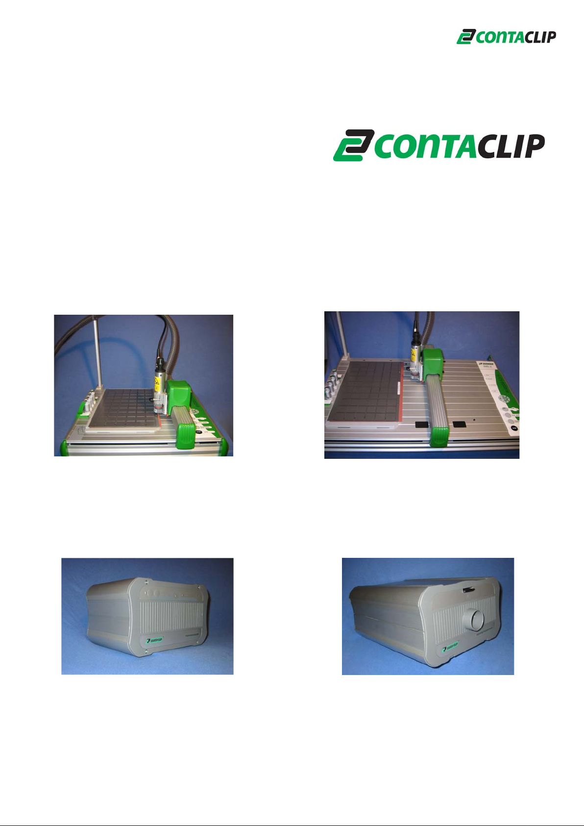
EMS-2
DIN A4 (half size)
Engraver-Controller (EC)
EMS-2
DIN A3 (full size)
Engraver-Vacuum-Cleaner (EVC)
©
Release: July 21,10
Page 2

Guide to
adapting the Engraving unit to the EMS-2
Content
1. Adaptation EMS-2 Engraver.........................................................................2
2. Scope of supply............................................................................................3
3. Connection and assembly of the Engraver to the EMS-2.............................5
3.1 Assembly of the support arm for cable and hose...................................5
3.2 Disassembly of the Pen-holder from the EMS-2....................................5
3.3 Installing the Engraving head.................................................................6
3.4 Arrange Vacuum cleaner (EVC) and Controller (EC).............................6
3.5 Connecting the cables............................................................................7
3.6 Installing the Engraving spindle into the Engraving head ......................7
3.7 Alignment of the Engraving unit.............................................................7
3.8 Connections at the Engraving head.......................................................8
3.9 Placing the cover on the Engraving head ..............................................8
3.10 Test run.................................................................................................8
3.11 Placement of the Engraving material....................................................8
3.12 Buttons and indications of the Engraver-Controller (EC).....................8
4. Adjustment of the Engraving depth...............................................................9
5. Changing the Engraving needle.................................................................10
6. Engraver-Vacuum-Cleaner (EVC) Bag and Filter change ..........................11
6.1 Changing the Vacuum cleaner bag ......................................................11
6.2 Changing or cleaning of Motor dust-filter..............................................11
7. Instructions for cleaning the Engraving spindle..........................................11
8. Troubleshooting..........................................................................................12
9. Accessories ................................................................................................13
10. Technical data...........................................................................................14
11. General Safety Rules................................................................................15
11.1 Tool Safety Instructions ......................................................................16
1
Page 3
1. Adaptation EMS-2 Engraver
The engraving unit was specifically designed for getting adapted to the EMS-2, other
plotters will not be able to carry the unit.
The main purpose of the engraving unit is the
engraving of plastic signs. Respective double
sided material is available through local
suppliers. As an alternative, pre-cut plastic
material in different sizes is available through us,
please refer to accessories.
The use of lubrication and cooling fluid is not
suggested at all, as the vacuum cleaner EVC
cannot handle any fluid.
Note: Please use the engraving needles
supplied with the system only. Any other brand
will possibly lower the engraving result, as
we will not accept any quality claim.
Important Notice: Please read the General Safety Rules carefully and follow them, as
the manufacturer shall under no circumstances be liable for damage or any
personal injury caused by not following the Safety Rules and Instructions.
2
Page 4
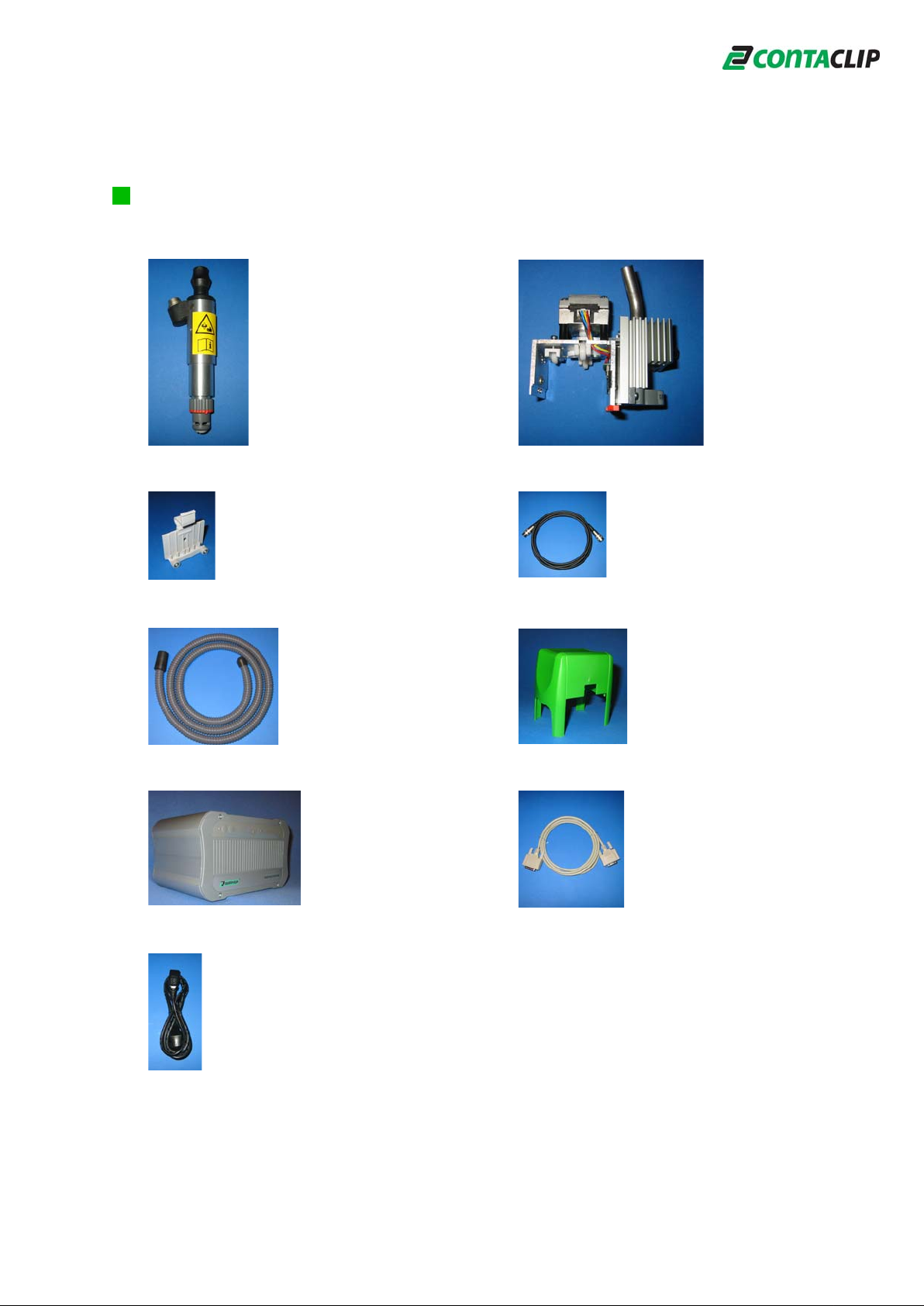
2. Scope of supply
1. Engraving spindle 2. Engraving head
3. Support bearing for engraving head 4.Connecting cable for Engraving spindle
5. Hose for Vacuum cleaner 6.Engraving head cover
7. Engraver-Controller (EC) 8. Connecting cable for EC - EMS-2
9. Power cord for EC
3
Page 5
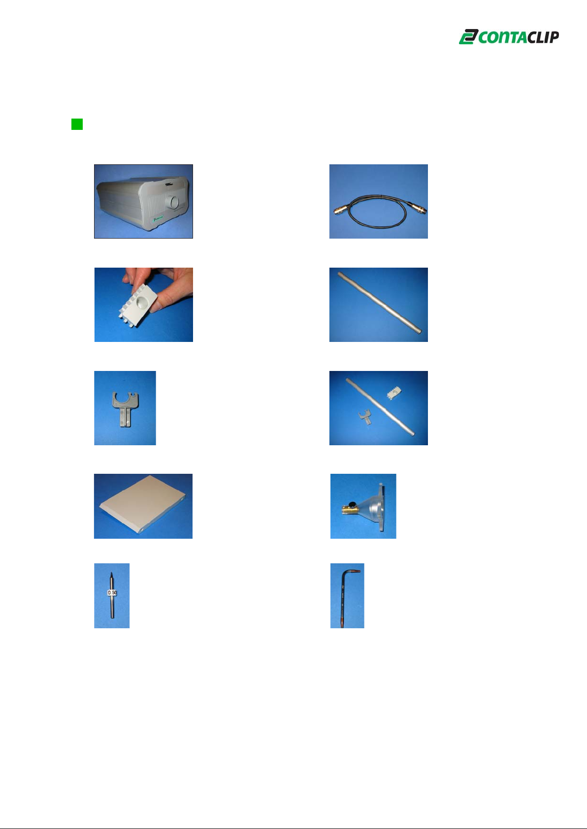
Scope of supply
10. Engraver-Vacuum-cleaner (EVC) 11. Connecting cable for EVC
12. Support bracket for holding pipe 13.Holding Pipe
14. Support arm for holding hose and cable
15. Calibration plate for alignment 16. Tool for adjusting engraving needle
17. Engraving needle .5 mm 15° 18. Tool for adjusting engraving head
4
Page 6
3. Connection and assembly of the Engraver to the EMS-2
The connection and assembly of the engraving unit is easy to work through. The
components need careful treatment in order to prevent any damage.
The following describes the assembly process in detail.
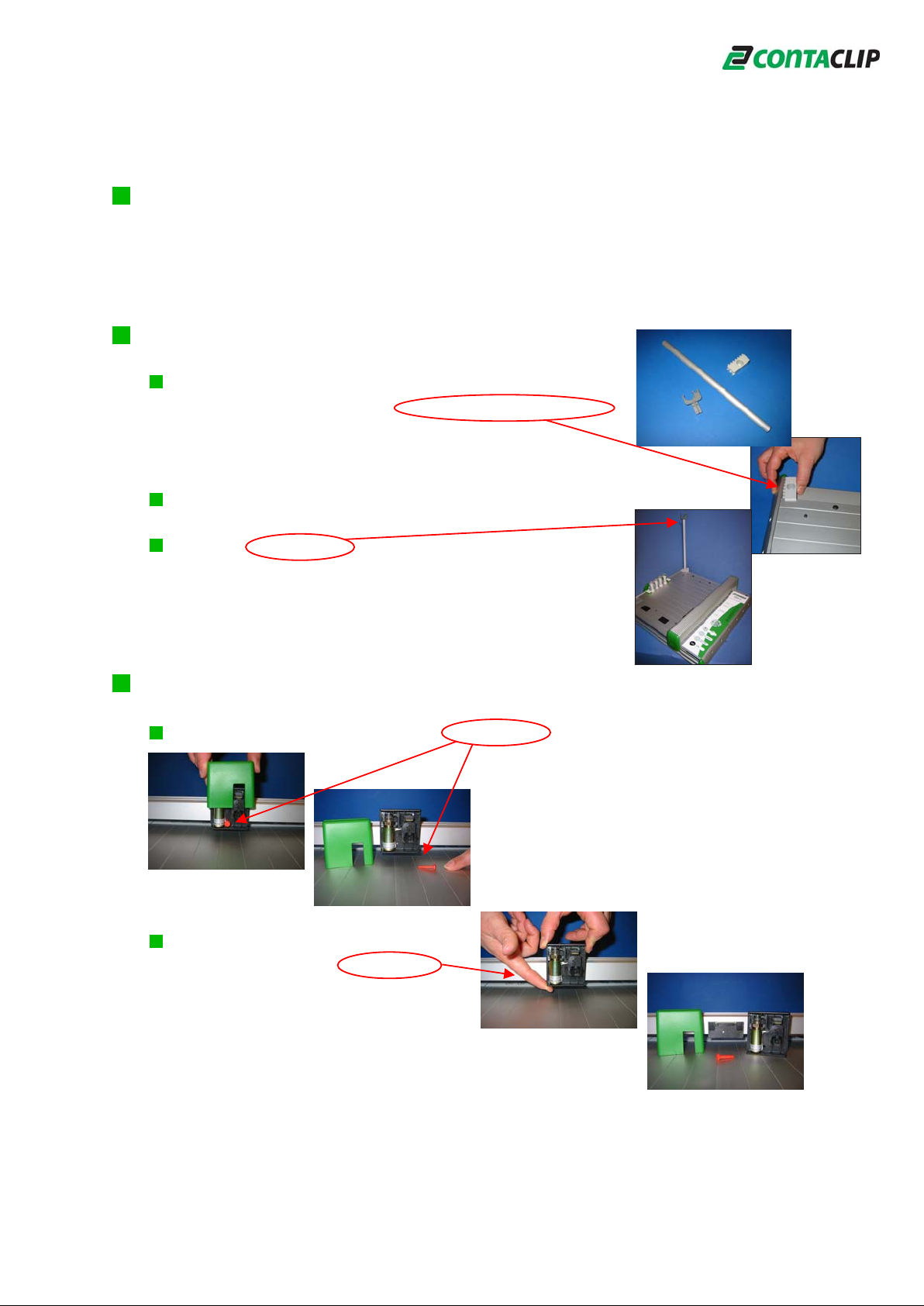
3.1 Assembly of the support arm for cable and hose
Place the support bracket on top of the base plate as
shown in the picture and push into the side of the plotter
profile.
Insert the aluminum pipe into the support bracket
Place the support arm into the opposite side, holding the
cable and hose.
3.2 Disassembly of the Pen-holder from the EMS-2
Remove the plastic cover and the safety lock.
Slightly tilt the pen-holder and release
from the holding bar by pulling up.
The unit can be very tight and fixed in the bar.
Remove the pen-holder very carefully to prevent
damaging the holding bar.
5
Page 7

3.3 Installing the Engraving head
Please pay attention to inserting the engraving
head on both sides.The holding bar must be
parallel.
Press the engraving head down to its limit,
support the holding bar manually from the
bottom side in order to prevent damaging the
holding bar.
Secure the engraving head.
In order to prevent any movement of the engraving head during
the process, the safety lock needs to be closed by pushing to
the middle on both sides as shown.
Double check the proper mounting.
Install the support bearing.
Place the support bearing as shown,
snap in place.
Later the horizontal alignment of the engraving head
will be done by using the tool.
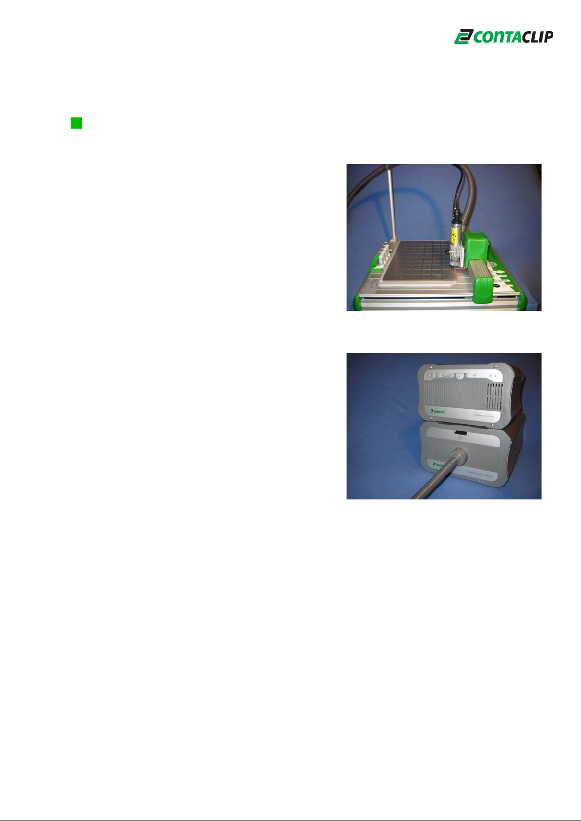
3.4 Arrange Vacuum cleaner (EVC) and Controller (EC)
Arrange the units behind the EMS-2, as shown.
6
Page 8

3.5 Connecting the cables
Connect the Vacuum cleaner cable between the
Vacuum cleaner EVC and the Controller EC, tighten
the plugs on each end.
Connect the Controller cable between the EMS-2 and
the Controller EC, tighten the plugs on each end.
Connect the power cord to the Controller EC and the
electrical outlet.
The main fuse (4 amp) is placed
within the socket next to the
On / Off switch.
3.6 Installing the Engraving spindle into the Engraving head
Insert the engraving spindle into the engraving head as shown and
tighten the spindle with the clamp screw. The engraving spindle has
a 0.5 mm engraving needle pre-installed from the factory.
The red mark of the depth controller needs to be in line with the
arrow of the engraving head.
Important: Do not turn the depth controller in any direction as the
precise alignment will not be possible.
Attention: Please read and follow the safety
instructions for using.
3.7 Alignment of the Engraving unit, only necessary for the first start up!
Place the calibration plate on the
EMS-2 as shown.
Move the arm with the engraving head
manually against the calibration plate, the
EMS-2 must be turned off.
Align the engraving head vertically, turn the screw with the tool
CW or CCW as shown.
7
Page 9

3.8 Connections at the engraving head
Manually move the arm with the engraving head to the
lower right corner, the EMS-2 must be turned off. Connect the vacuum
hose to the engraving head as shown and clip the hose into the support
arm placed in the pipe with a slight bend. Connect the opposite end to
the Vacuum cleaner EVC.
The connection of the cable between the engraving spindle and the
Controller EC is the same process.
Tighten all screws at the connection plugs.
3.9 Placing the cover on the Engraving head
Place the cover over the engraving head and push the cover
down to the limit.
3.10 Test run
First turn on the power with the switch located at the back of the Controller EC.
Then turn on the EMS-2 and the engraving unit moves to its zero position
alignment, noticeable with a short noise. Once aligned the EMS-2 arm will be in zero
position alignments in z, x and y direction, turn off the EMS-2 thereafter.
3.11 Placement of the Engraving material
Place the support plate together with the engraving material on the EMS-2 Engraver
as shown on the label, (place the label per instructions of
support plate). Move the arm manually, with the engraving
head, over the engraving material. The EMS-2 must be
turned off.
Important: The distance between the lower end of the
spindle and the engraving material must be 2 mm. If the distance is
lower or higher re-check the alignment of the engraving unit with
the calibration plate. Now turn on the Controller EC and the
Vacuum cleaner EMS-2 in order to start the engraving unit.
3.12 Buttons and indications of the Engraver-Controller (EC)
The power switch of the Controller EC is placed at the back, once switched on
the green LED is lit. The EC controls the Vacuum
cleaner EVC automatically. In case the Vacuum cleaner EVC
should be operated manually e.g. to clean the engraved material
after the job is completed, use the ON and OFF button.
The proper operation of the spindle is indicated with the yellow
LED, any failure of the spindle will be indicated with the red LED
and the engraving will be stopped.
8
Page 10

4. Adjustment of the Engraving depth
The engraving depth will be adjusted through the depth controller at the bottom of the
engraving spindle. Depending on the size and the angle of the engraving needle as
well as the engraving depth, certain engraving widths could be achieved.
We suggest to engrave with the needle angle of 15 degrees for normal use.
The engraving needles are available
in sizes of .2; .3; .4; .5; .7; 1.0 mm.
Special sizes are available on request.
According to the samples shown,
different results of the engraving can be achieved.
The adjustment of the engraving depth will be done by manually
turning the depth controller. zero position
Each clock wise turn will increase the depth, each
counter clock wise turn will reduce the depth. With
the turn of the controller a notch is noticeable.
With each notch the engraving needle will 1 mm
change position of .025 mm in either direction. One
complete turn counts 40 notches and equals to 1 mm
in the change of depth of the engraving needle.
2 mm
The depth of the engraving can be checked
at the scale on the left side of the spindle.
Attention: The point of the engraving needle is very sensitive and needs to be
treated carefully. Prevent damaging the point, if damaged the engraving quality
will be extremely limited.
9
Page 11

5. Changing the Engraving needle
In order to change the engraving needle, please follow the steps below:
Loosen the clamp screw at the
engraving head and take out the
spindle. The connecting cable
can be left on.
Unscrew the depth controller of the
the engraving spindle completely.
Attention: Engraving needle and spindle could be hot!
Thereafter, the clamp holding the needle needs to be opened
by pressing the knob at the end of the spindle
towards the needle. Find the position with the
lowest point and turn the knob
CCW, that opens the clamp and
the engraving needle can be
pulled out carefully.
Attention: Open the clamp only a few turns to pull out the engraving needle,
open the clamp completely for cleaning purpose only.
In order to insert the engraving needles with the correct length, use always the
tool. Please use the engraving needles supplied by us only, with the use of other
brands we will not be responsible for the lack of quality or any damage to the
unit.
Attention: The point of the engraving needle is very sensitive and needs to be
treated carefully. Prevent damaging the point, if damaged the engraving quality
will be extremely limited. Use always the tool for inserting the new needle.
Insert and fix a new engraving needle within
the tool and push the needle with the tool
into the spindle.
Close the clamp by turning the knob CW,
unscrew and remove the tool.
Screw the depth controller onto the
spindle.
The controller has reached its zero
position with a distance of approx. 3 mm to the spindle.
Use the tool as a distance check by holding the one
side open washer between the depth controller and the
spindle, as shown.
Insert the spindle into the engraving head by checking the position
of the red mark of the depth controller, needs to be in
line with the arrow at the engraving head. Tighten the
spindle with the clamp screw.
10
Page 12

6. Engraver-Vacuum-Cleaner (EVC) Bag and Filter change
The Vacuum cleaner EVC was specifically designed for use with the EMS-2
Engraver in order to pickup the engraving dust directly at the spindle, stored in a bag.
6.1 Changing the Vacuum cleaner bag
The Vacuum cleaner bags are standardized. Replacement bags are
available through us or any retailer.
For changing the bag gently press up on the knob at the Vacuum
cleaner EVC and the front closure with the bag will open.
Before taking out the bag please remove the hose by
slightly turning and pulling.
Remove the bag, insert and secure a new bag.
To close up the unit please reverse the above steps.
6.2 Changing or cleaning the Motor dust-filter
Once the front closure is open as described above, the internal
motor dust-filter can be removed. You need to follow the housing of
the bag and take out the filter with your hand. Depending on the
number of engravings the filter needs to be cleaned from time to
time, replacement filters are available through us only.
7. Instructions for cleaning the Engraving spindle
The engraving spindle is a very sensitive item and needs to be treated carefully.
Use the spindle in low dust environments only. A high dust concentration at the work
bench will cause clogging of the ball bearings and consequently the spindle can be
off-centered.
Never use pressurized air for cleaning the spindle because of loosing the inside
lubrication of the bearings. Never use any lubrication during the engraving process.
Do not clean the spindle with water.
If any dust is collected within the clamp, possible reason for
missing quality, take out the needle and unscrew the clamp
completely by using the knob.
Clean the front part of the clamp saddle
carefully using a Q-Tip as shown.
11
Page 13

8. Troubleshooting
SolutionProblem
The Engraving controller
EC cannot be switched on. The
green “Power”-LED is not on.
The red LED “spindle failure”
at the Engraving controller EC
is on.
Attention: The engraving will
be stopped immediately.
Unable to engrave Check the connection cable between the Controller EC and the Plotter
The engraved result is poor,
letterings are un-consistent,
lines are not sharp
Check the power cord, connected correctly and the mains supply is
available at the outlet.
Next, check the AC input fuse at the backside of the Controller EC.
Disconnect the cable at both ends and pull out the fuse holder,
located beneath the power on/off switch,
see page 8 chapter 3.5 of the manual.
The high RPM-spindle is either faulty or overloaded. To verify, hold
down the ON and OFF button simultaneously at the
Controller EC. The Vacuum cleaner EVC starts to run, shortly after the
engraving spindle. The RPM of the spindle can be altered
using the ON or OFF button.
The spindle needs to be replaced if the red LED (error indication) is
still on.
EMS-2. Pay attention to the messages of the labeling software on the
screen. Switch on the Controller EC first and then the EMS-2. Verify
also, the correct seating of the engraving head and the cable
connection between the Controller EC and the spindle.
First check if the engraving needle is broken somehow damaged,
in case the needle needs to be replaced.
Check if engraving dust remains in the head or clamp of the spindle.
Unscrew the depth controller and the clamp carefully. Clean the depth
controller and the clamp of the spindle according to the manual
“Instructions for cleaning the Engraving spindle”,
see page 12 chapter 7 of the manual.
Attention: Do not use pressurized air for cleaning!
The engraving depth is not
sufficient.
The 2 mm distance between the depth controller and the surface of
the engraving material might be not correct. Move the arm manually
with the engraving head over the engraving material, the EMS-2
must be turned off and check the distance,
see page 9 chapter 3.11 of the manual.
Make sure the engraving needle and depth controller are adjusted
correctly with the included tool, see page 11 chapter 5 of the manual.
12
Page 14

9. Accessories
Description Part no. Picture
Engraving needle 15 o
set .2; .3; .4; .5; .7; 1 mm
Engraving needle 15 o .2 mm
Engraving needle 15 o .3 mm
Engraving needle 15 o .4 mm
Engraving needle 15 o .5 mm
Engraving needle 15 o .7 mm
Engraving needle 15 o 1 mm
Vaccum cleaner bag, set of 5 pcs.
Universal support plate
for Engraving and Plotting
half size (DIN A4)
Universal support plate
for Engraving and Plotting
full size (DIN A3)
Engraving material please call for details
full size DIN A3 / half size DIN A4
blank sheet or pre-sized tags
13
Page 15

10. Technical data
Environmental conditions Operation: 10oC (50oF) up to 35oC (95oF)
for all units rel. Humidity: 35% to 75% no condensation
Storage: -10
rel. Humidity: 10% to 90% no condensation
Safety certificate: EN 60950-1
Interference safety compliance: EN 55022 B
EN 61000-4-2 to 6
EN 61000-4-11
EN 61000-3-2 and 3
10.1 Engraving Spindle
Revolution speed: min. 5000 RPM, max. 50.000 RPM
Torque: 6 Ncm
Frequency: 83-830 Hz
Power consumption: max. 60 W
Clamp: Shaft diameter 3 mm (.118 inch)
Clamp mechanism: Head clamp
Revolution accuracy with clamp: .03 mm (.00118 inch)
Motor details: Three-phase asynchronous, brushless
Housing: Aluminum
Holding diameter: 25 mm (.984 inch)
Ball bearing: Double, steel, permanent lubricated
Cooling: Air through integrated fan
Weight: approx. 280 g (.62 pounds)
Overall length: approx. 175 mm (6.89 inch)
Usage: Engraving only
Guaranteed bearing lifetime : min. 1000 hours at appropriate
usage
o
C (14oF) up to 50oC (122oF)
10.2 Engraver-Controller (EC)
Voltage supply: 110-240 V ~ 50-60 Hz
Mains fuse: 4A, slow-blow
Measurements: 180 mm x 250 mm (7.08 inch x 9.84 inch)
Weight: approx. 2.7 kg (5.95 pounds)
10.3 Engraver-Vacuum-Cleaner (EVC)
Input voltage: 24 VDC
Power consumption: max. 55 W
Vacuum cleaner bag: Swirl Type Y98
Measurements: 350 mm x 250 mm (13.78 inch x 9.84 inch)
Weight: approx. 4.6 kg (10.15 pounds)
14
Page 16

11. General Safety Rules
WARNING: “READ ALL INSTRUCTIONS” Failure to follow the SAFETY RULES listed BELOW,
and other safety precautions, may result in serious personal injury.
“SAVE THESE INSTRUCTIONS”
Work Area
• KEEP WORK AREAS CLEAN. Cluttered areas and benches invite accidents.
• AVOID DANGEROUS ENVIRONMENTS. Don’t use power tools in damp or wet locations. Do not expose power tools to rain.
Keep work area well lit.
• AVOID GASEOUS AREAS. Do not operate portable electric tools in explosive atmospheres in presence of flammable liquids or
gases. Motors in these tools normally spark, and the sparks might ignite fumes.
• KEEP CHILDREN AWAY. Do not let visitors contact tool or extension cord. All visitors should be kept away from work area.
Personal Safety
• GUARD AGAINST ELECTRIC SHOCK. Prevent body contact with grounded surfaces. For example; pipes, radiators, ranges
and refrigerator enclosures. Rubber gloves and non-skid footwear are recommended when working outdoors, where damp or wet
ground may be encountered. A Ground Fault Circuit Interrupter protected power line must be used for these conditions.
• DRESS PROPERLY. Do not wear loose clothing or jewelry. They can be caught in moving parts. Wear protective hair covering to
contain long hair.
• USE SAFETY EQUIPMENT. WEAR SAFETY GOGGLES or glasses with side shields. Wear hearing protection during extended
use of power tools and dust mask for dusty operations.
• STAY ALERT. USE COMMON SENSE. Watch what you are doing. Do not operate tool when you are tired or under influence of
drugs.
• REMOVE ADJUSTING KEYS AND WRENCHES. Form habit of checking to see that keys and adjusting wrenches are removed
from tool before turning it on.
• AVOID ACCIDENTAL STARTING . Don’t carry plugged in tool with finger on switch. Be sure switch is OFF when plugged in.
• DON’T OVERREACH. Keep proper footing and balance at all times.
• BEFORE CONNECTING THE TOOL to a power source (receptacle, outlet, etc.), be sure voltage supplied is the same as that
specified within the technical data or on the nameplate of the tool. A power source with voltage greater than that specified for the
tool can result in serious injury to the user — as well as damage to the tool. If in doubt, DO NOT plug in the tool. Using a power
source with voltage less than the nameplate rating is harmful to the motor. “VOLTS AC” designated tools are for Alternating
Current 50-60 Hz only. “VOLTS DC” designated tools are for Direct Current. Do not use AC designated tools with DC power
source. Do not use electronic speed controlled tools with DC power source.
Tool Use and Care
• DON’T FORCE TOOL. It will do the job better and safer at the rate for which it was designed.
• USE THE RIGHT TOOL. Don’t use tool for purpose not intended, only as described in the manual..
• USE THE SPINDLE ONLY WHEN INSERTED IN THE ENGRAVING HEAD.
• SECURE WORK. Make sure the support plate is always adhesive enough holding the material, if not clean the plate with clear
water. Never use your hand holding the material in place. Use only original support plates holding the material.
• DON’T ABUSE CORD. Never carry tool by cord or yank it to disconnect from receptacle. Keep cord from heat, oil and sharp
edges. Always keep cord from spinning blade, bits or any other moving part while the tool is in use.
• INDOOR USE ONLY!
• THE USE OF ANY OTHER ACCESSORIES not specified in this manual may create a hazard and is strictly forbidden.
• DISCONNECT TOOLS. When not in use; before servicing; when changing blades, bits, cutters, etc.
• STORE IDLE TOOLS. When not in use, tools should be stored in dry, high or locked up place — out of the reach of children.
• DO NOT ALTER OR MISUSE TOOL. These tools are precision built. Any alteration or modification not specified is misuse and
may result in a dangerous condition.
• MAINTAIN TOOLS WITH CARE. Keep tool clean for better and safer performance. Follow instructions for changing
accessories. Inspect tool cords periodically and if damaged, have repaired by an authorized service facility. Inspect
extension cords periodically and replace if damaged. Keep engraving unit dry, clean and free from oil and grease.
• CHECK DAMAGED PARTS. Before further use of the tool, a guard or other part that is damaged should be carefully checked to
determine that it will operate
parts, breakage of parts, mounting, and any other conditions that may affect its operation. A guard or other part that is damaged
should be properly repaired or replaced. Have defective switches replaced. Do not use tool if switch does not turn it on or off.
• ALL REPAIRS, electrical or mechanical, should be attempted only by trained repairmen. Contact the nearest authorized repair
service facility. Use only original replacement parts, any other may create a hazard.
properly and perform its intended function. Check for alignment of moving parts, binding of moving
15
Page 17

11.1 Tool Safety Instructions
• Do not reach in the area of the spinning bit. The proximity of the spinning bit to your hand may not always be obvious.
• Never start the tool while engaged, by any reason, in the material. The bit cutting edge may grab the material causing loss
of control of the tool.
• Always disconnect the power cord from the power source before making any adjustments or attaching any
accessories. You may unexpectedly cause the tool to start leading to serious personal injury.
• Do not leave a running tool unattended, turn power off. Only when tool comes to a complete stop it is safe to change bits.
• Do not touch the bit or spindle after use. After use the bit and spindle are too hot to be touched by bare hands.
• Do not use the tool for any other purpose than described in the manual!
• If the workpiece or bit becomes jammed or bogged down, turn the tool “OFF” by the switch. Wait for all moving parts to stop and
unplug the tool, then work to free the jammed material. If the switch to the tool is left “ON” the tool could restart
unexpectedly causing serious personal injury.
• Do not allow familiarity gained from frequent use of your rotary tool to become common place. Always remember that a
careless fraction of a second is sufficient to inflict severe injury.
• Do not alter or misuse tool. Any alteration or modification is a misuse and may result in serious personal injury,
Conta-Clip and the tool manfacturer shall under no circumstances be liable for damage or any personal injury caused
by misuse or not following the instructions.
WARNING: Some dust created by power sanding, sawing, grinding, drilling, engraving and other construction activities
contains chemicals known to cause cancer, birth defects or other reproductive harm.
Some examples of these chemicals are:
• Lead from lead-based paints,
• Crystalline silica from bricks and cement and other masonry products, and
• Arsenic and chromium from chemically treated lumber.
Your risk from these exposures varies, depending on how often you do this type of work. To reduce your exposure to these
chemicals: work in a well ventilated area, and work with approved safety equipment, such as those dust masks that are specially
designed to filter out microscopic particles.
Extension Cords
• Replace damaged cords immediately. Use of damaged cords can shock, burn or electrocute.
• If an extension cord is necessary, a cord with adequate size conductors should be used to prevent excessive voltage drop, loss
of power or overheating. The table shows the correct size to use, depending on cord length and nameplate amperage rating of
tool. If in doubt, use the next heavier gauge. Always use U.L. and CSA listed extension cords.
RECOMMENDED SIZES OF EXTENSION CORDS
NOTE: The smaller the gauge number, the heavier the cord.
Tool´s
Ampere
Rating
3-6
6-8
8-10
10-12
12-16
25 50
18
18
18
16
14 12
120 Volt A.C. Tools
Cord Length in Feet
Cord Size in A.W.G.
16
16
16
16
100 150
16
14
14
14
--
14
12
12
12
16
 Loading...