

Page 1
CONTA-Sign CS 5.2
Easy-Marking-System
Manual
Labeling Software CONTA-Sign CS 5.2
Release: July 16, 2014
Page 1 of 67
©
Page 2

Manual
labeling software 5.2
Table of contents
1. System requirements
2. Software installation
3. Output devices supported by the program
4. Basic program functions
5. Brief instruction
5.1 Choosing the labeling or engraving device
5.2 Select the labeling / engraving element
5.3 Labeling elements
5.4 Output of labeling data on output device
6. Manage and display of projects
7. Select, Copy, Paste, Delete
8. Instruction on how to use the labeling software
8.1 Choosing the labeling device
8.2 Select the labeling element
8.3 Labeling elements
8.4 Extended input of labeling data
8.4.1 Multiple labeling
8.4.2 Consecutive labeling
8.4.3 Importing labeling data from files
8.5 Insert graphical elements or pictures
9. Output of labeling data
9.1 Output on plotter
9.2 Output on engraver
9.3 Printing on an office printer
9.4 Printing on thermo transfer printer
10. Create layouts on tags
Page 2 of 67
Page 3

11. Designer /Layouter
11.1 Setting up marking tags and strips for plotters
11.1.1 Design a marking element with one tag group (one size)
11.1.2 Design marking elements with more than one group (multiple sizes)
11.1.3 Design marking strips
11.2 Setting up engraving tags for the engraving units
11.2.1 Design an engraving element with one tag group (one size)
11.2.2 Design engraving elements with more than one group
(multiple sizes)
11.2.3 Design a marking strip
11.3 Setting up label sheets for office printers
11.4 Setting up endless labels and strips for thermo transfer printers
11.4.1 Design endless labels
11.4.2 Design endless strip
12. Import/Export of labeling elements and labels created with various
designer versions
13. Special functions using plotter and engraving versions
13.1 Import of CAD files and output on plotter and engraving units
13.2 Shift of start point and correction of scale factor
13.3 Base plates and segments
13.4 Control print of the labeling data
13.5 Calibrating plotter and engraver versions
13.6 Assign the support plate to the labeling element
14. General information and adjustments
14.1 Zoom function
14.2 Select program language
14.3 Display and switching within open project files
14.4 Specify the standard font type
14.5 Preset the standard pen size
14.6 Software version
14.7 Check for updates
14.8 Help files
Page 3 of 67
Page 4

1. System requirements
PC with 1.8 GHz (min.), 512 MB RAM, graphic resolution 1024 x 768,
40 GB hard drive, USB interface / Windows 2000, XP, Vista and Windows 7/8
2. Software installation
First close all other applications.
Insert the software installation CD into your CD-ROM drive.
Installation will begin automatically. You should follow the on-screen instructions. If the
auto-start feature has been switched off on your PC, double-click to start the program
XXXX_setupx.x.xxxx_xxxxxx.exe.
When installation is complete, you can start the program by double-clicking on the
program icon. Install the driver for the output device from the CD acc. to your
operating system and follow the instructions.
Language selection is automatic according to the country-specific version of Windows.
For country-specific versions of Windows where the program provides no individual
language version, the English version is automatically installed. You can override the
settings under > Options
> Language setting.
3. Output devices supported by the program
The labeling and engraving software version 5.2 supports the following output
devices:
- Plotter
Labeling devices for labeling all current labeling elements that are used in switch
cabinets and plant construction.
- Plotter full size (DIN A3)
- Plotter Basic half size (DIN A4)
- Engraving Unit (option)
Engraving device for engraving plastic, aluminum and brass plates.
Connecting the engraving unit to one of the plotter versions provides you with access
to the following engraving devices:
- Engraver full size (DIN A3)
- Engraver Basic half size (DIN A4)
- Engraving Unit (dedicated)
- Engraver full size (DIN A3)
- Engraver half size (DIN A3)
Note:
The plotter versions and the engraving units can be run with this program solely via a
USB connection
.
Page 4 of 67
Page 5

- Office printer
To print any type of label sheet (DIN A3/A4).
- Thermo transfer printer
To print endless labels and endless strips
4. General program functions
Basic software structure
Various labeling devices such as plotters, engravers, office and thermo transfer
printers can be controlled using the labeling software. All labeling elements stored in
the database are assigned to the relevant labeling devices. When the labeling device
has been selected, the only labeling elements provided will be those that the particular
device can print or engrave.
If, for example, the office printer is selected as the output device, the label sheets set
up in the database are automatically provided for selection.
The corresponding designer enables new templates for various output devices to be
set up quickly and easily.
General procedure for using the labeling software
1. Choosing the labeling or engraving device
2. Select the labeling / engraving element
3. Labeling elements
4. Output of labeling data on the output device
Page 5 of 67
Page 6
5. Brief instruction on how to use the labeling software
5.1 Choosing the labeling or engraving device
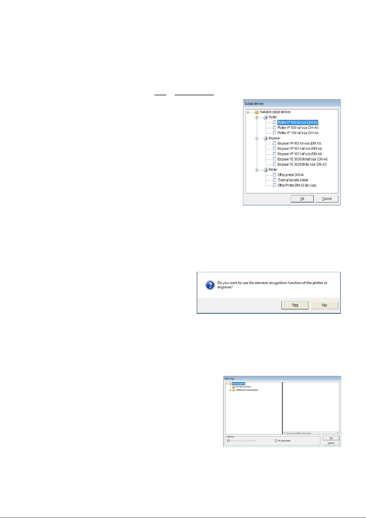
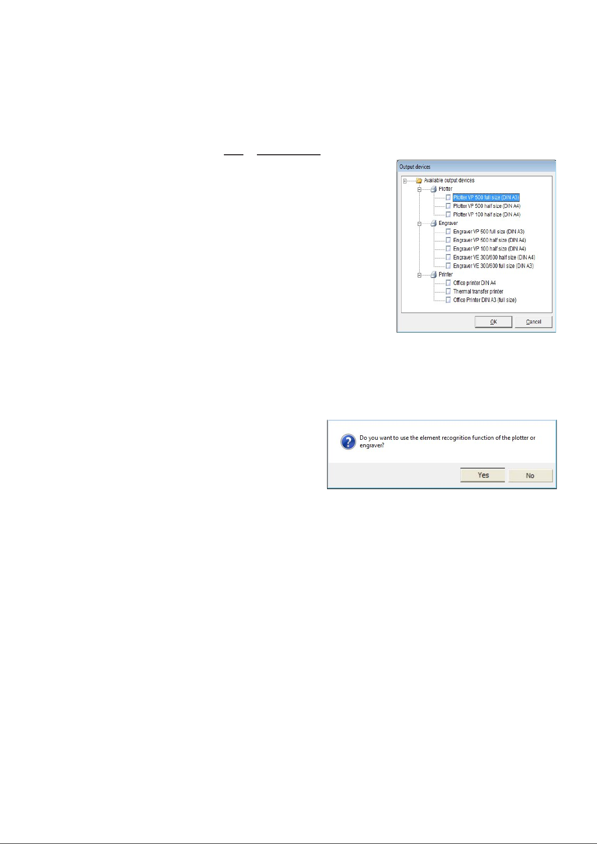
From the menu bar, select > File > New project. The window to select the labeling or
engraving device opens. When you have chosen and
confirmed the relevant output device, the program
provides you with a list of all labeling element
manufacturers for the output device used.
You can pre-select the output device to be used by
clicking with the right mouse button on the device name
and select as standard. Opening a new project by
clicking on the Icon New Project selects always the
standard device.
When you have chosen the plotter or engraver and the
respective device is switched on and connected to your
PC via the USB cable, you can preselect the labeling
elements.
In this instance, the message appears:
> Do you want to use the element recognition function of the plotter or
engraver? <.
If you confirm by answering Yes, the software imports the identification of the
support plates placed from the plotter and only provides you with the manufacturers of
the labeling elements that can be printed
or engraved on the support plates used.
Note: Only for full size plotter / engraving
option
5.2 Select the labeling element
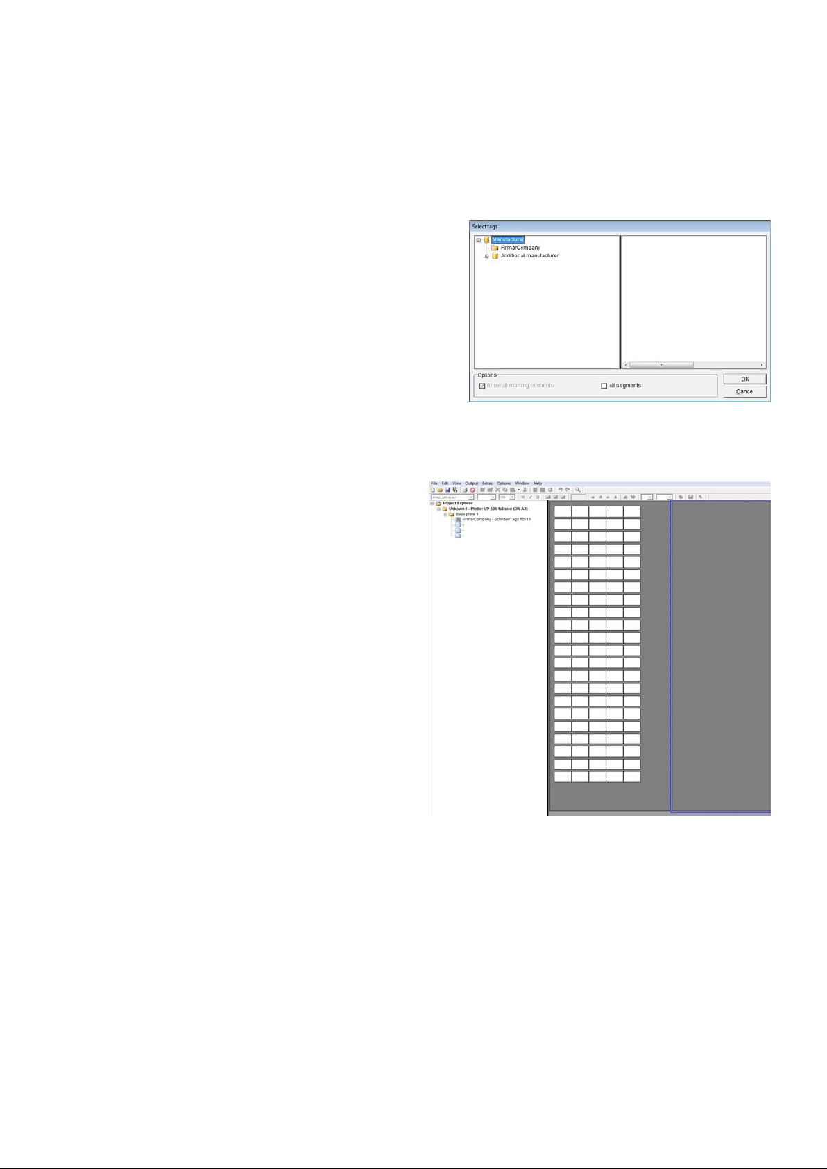
Click on the relevant manufacturer to select the labeling element required. It is then
displayed on screen.
If you have switched on element recognition for
the plotter or engraver, the individual segments
will be displayed on screen. Double-click on the
segment required. This displays only the
manufacturers of labeling elements that can be
used with the support plate fitted.
Page 6 of 67
Page 7
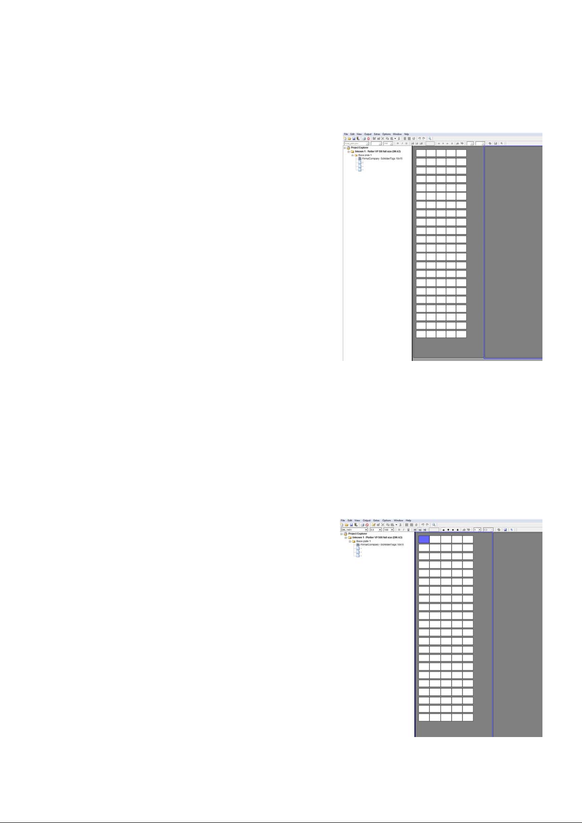
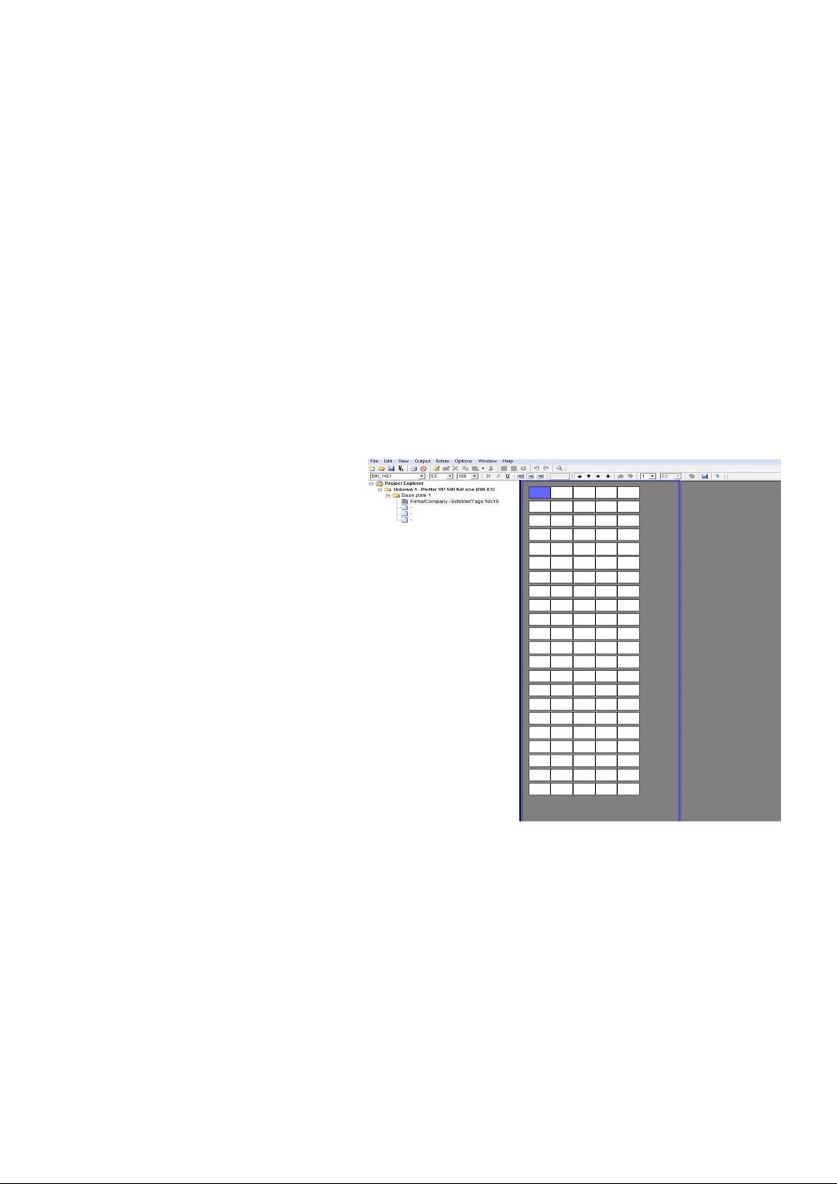
Double-click to select the manufacturer and then the element to be printed.
The relevant template appears on screen.
5.3 Labeling elements
You can choose from a variety of options to label tags or labels.
- Label straight onto the tag
Click on the tag to be labeled. The tag is selected and the toolbar shows the default
settings for selecting the font style, font size, etc.
You can change the settings and enter the
labeling text directly.
When you have labeled individual tags, you can copy, paste, insert, delete, cut or
remove tags as well as add new tags.
A detailed description of how to select, copy,
paste, delete tags you can find within
Chapter 7 of this manual.
Page 7 of 67
Page 8
- Extended input of labeling data
If you wish to create multiple labels or consecutive labeling, or if you want to import
data from Excel or text files, double-click on the tag where labeling should begin.
A window subsequently opens enabling you to use the extended input options to
create labeling data. Click on Apply to go back show the entries on the tags.
More details you can find within Chapter 8.4.
5.4 Output of labeling data to the output device
When you have entered all labeling data, click on the printer icon in the toolbar.
The window for the relevant output device appears. You can then use this to enter all
the settings you require. More details you can find within Chapter 9.
Page 8 of 67
Page 9
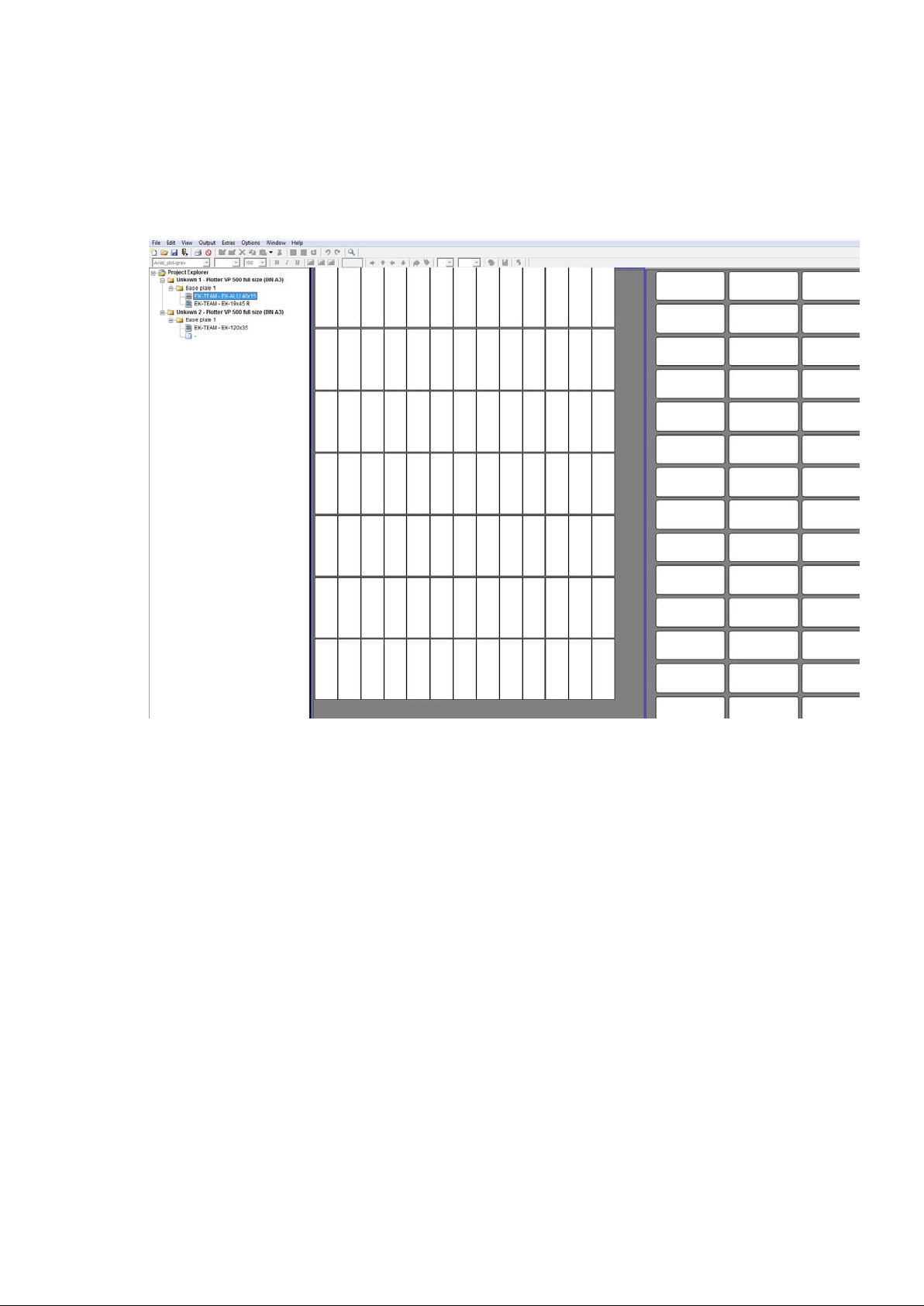
6. Manage and display projects
As soon as you have opened or created a new project the Project Explorer is shown at
the left side of the screen.
Within the explorer view all open projects with the respective base plates and
segments are shown, providing a complete overview.
With each project the name, output device, number of base plates and segments used
are displayed.
Additional tags can be placed by clicking on segments not used.
Page 9 of 67
Page 10

7. Select, Copy, Paste, Delete
The software provides multiple functions in order to select, copy, paste, insert, delete
tags.
Select tags
- Single click on one tag
Selecting the tag for labeling directly
- Double click on one tag
Selecting one tag and all blank tags following for labeling until next tag with text
- Double click on one tag
Selecting one tag and all blank tags following for labeling until next tag with different
number of lines or justification appears
Select a tag and open context menu with right mouse button
- All labeling new
Starting from the selected tag all following tags on the base plate are highlighted
despite of having labeling already
- Select all of the labeled tags same type
Starting from the selected tag all following tags with the same number of lines and
justification, even through further base plates, are highlighted for changing parameter
settings in the tool bar.
- New labeling
Starting from the selected tag all following tags are highlighted until next tag with
different number of lines or justification appears
- Edit labeling
Edit selected tag
Page 10 of 67
Page 11

Additional features selecting tags
- Selecting groups of tags in order to edit, copy, paste and delete
Click on the tag with the left mouse button you like to start to select the group and drag
with the mouse the area you like to select. If you like to select another group or single
tags in addition, hold down the Control button and select in the same way the tags.
Note: Only tags of the same type can be selected at the same time for making
changes such as Edit, Copy, New, Delete using the context menu.
Do you want to send only dedicated tags or labeling areas to the output device, select
as described before and click on the printer icon.
- Selecting areas for labeling
Hold down the Alt button and click with the left mouse button you like to start to select
the group and drag with the mouse the area you like to select. If you like to select
another area, group or single tags in addition, hold down the Alt button and select in
the same way. Once selected, send the labeling to the output device by clicking on the
printer icon.
- Copy, paste and delete of selected tags
After selecting the tags as described above, you can copy, paste and delete tags using
the context menu.
There are three options available to paste selected tags.
If you like to carry all labeling information with to the next tags, such as number of
lines, justification, font settings etc. click on the first tag you like to start to paste the
copied tags, then open with the right mouse button the context menu and select
> Paste labeling special
or use Control I to paste the information. Already existing
tags with text or symbols could be overwritten.
If you like to carry only the text information to the next tags, click on the first tag you
like to start to paste the copied tags, then open with the right mouse button the context
menu and select > Paste labeling
or use Control V to paste the information as text
only with the default settings. Already existing tags with text or symbols could be
overwritten.
Further, if you like to paste labelings with reverse sequence select and copy the group
of tags with the separator used. Click on the first tag you like to start to paste the
copied tags, then open with the right mouse button the context menu and select
> Paste labeling with reversed sequence based on separator
in addition select the separator used.
(Example: copy from the left, paste to the right)
Page 11 of 67
Page 12
8. Instruction on how to use the labeling software
8.1 Choosing the labeling or engraving device
Follow the menu path > File > New project. The window to select the labeling or
engraving device opens. When you have chosen and
confirmed the relevant output device, the program
provides you with a list of all labeling element
manufacturers for the output device used.
You can assign the output device by selecting and
setting with the right mouse button as standard.
When you have chosen the plotter or engraver and the
respective device is switched on and connected to your
PC via the USB cable, you can preselect the labeling
elements.
In this instance, the message appears:
> Do you want to use the element recognition function of the plotter or
engraver? <.
If you confirm by answering Yes, the
software imports the identification of the
support plates placed from the plotter and
only provides you with the manufacturers
of the labeling elements that can be printed
or engraved on the support plates used.
Note: Only for full size (A3) plotter / engraving option
Page 12 of 67
Page 13
8.2 Select the labeling element
Click on the relevant manufacturer to select the labeling element required.
If you have switched on element recognition for the plotter or engraver, the individual
segments will be displayed on screen.
Double-click on the segment required. This
displays only the manufacturers of labeling
elements that can be used with the support
plates fitted.
Double-click to select the manufacturer and
then the element to be printed.
The relevant template appears on screen.
If you are not using the element recognition,
or using the VE 600, the labeling element will be shown on the screen by selecting
with a click.
There are different sizes, shapes and
material thicknesses available, in this
case tags with the size 10 x 15 mm
were selected.
If the labeling element, label sheet or endless labels are not available in the database,
you can use the designer variant to set these up at any time.
Page 13 of 67
Page 14
8.3 Labeling elements
You can choose from a variety of data input options to label tags or labels.
- Label straight onto the tag
Click on the tag to be labeled. The tag is selected and the toolbar shows the default
settings for selecting the font style, font size, etc.
You can change the settings and enter the labeling text directly. When you have
labeled individual tags, you can copy, insert, delete, cut or remove tags as well as add
new tags.
A more detailed instruction of how to select, copy, paste and delete tags you can find
within chapter 7.
Page 14 of 67
Page 15
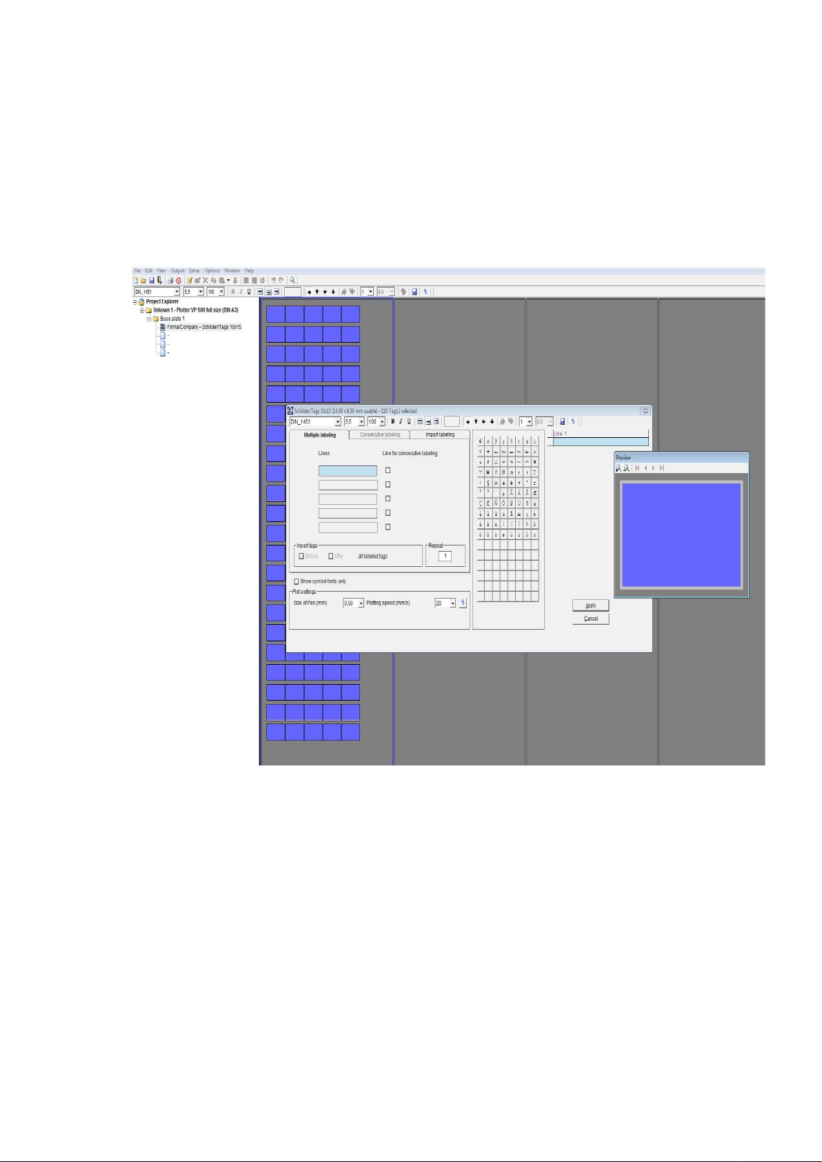
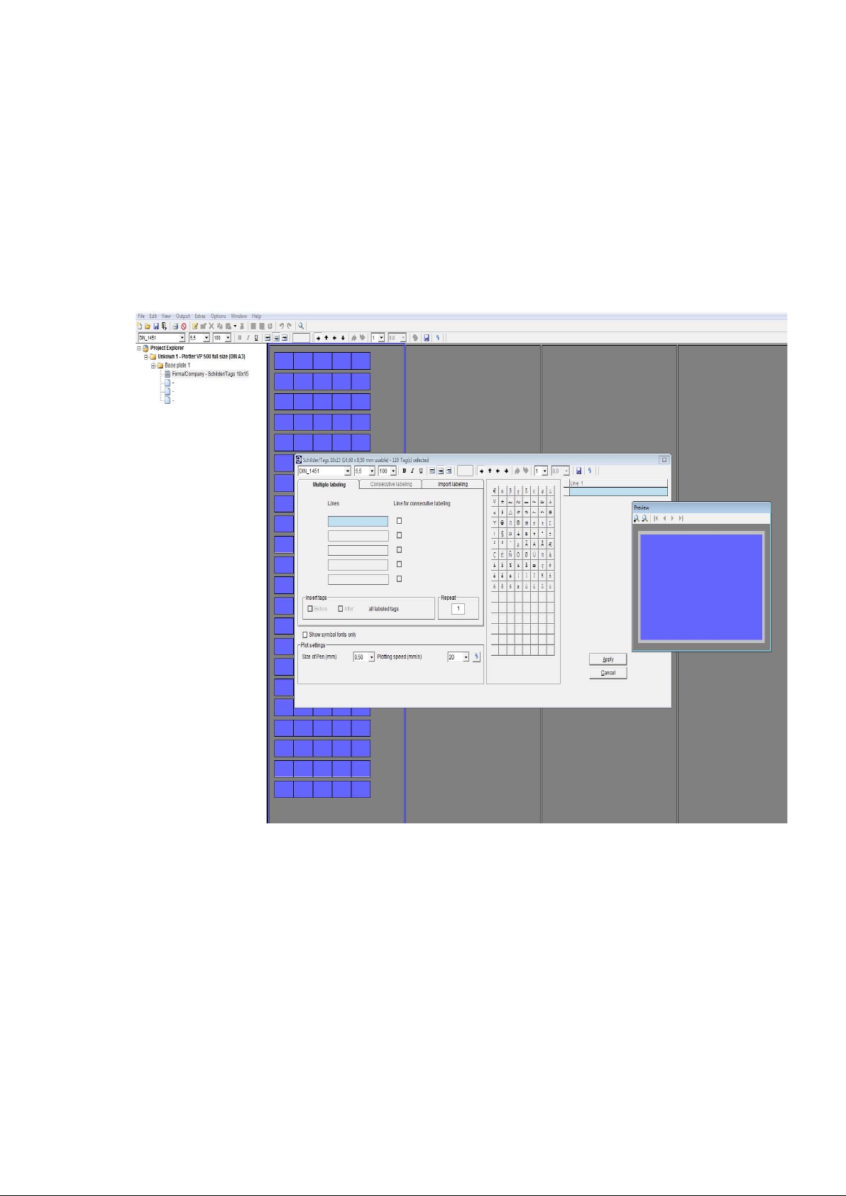
8.4 Extended input of labeling data
If you wish to set up multiple or consecutive labeling, or if you want to import data from
Excel or text files, double-click on the tag where labeling should begin. A window
subsequently opens enabling you to use the extended input options to create labeling
data.
Within the pre-view window the exact orientation and image of the text or graphic is
shown.
The top line of the window that has now opened next to pre-view provides you with
information about the tag or element as well as the number of tags available.
Underneath the line of information, a number of settings are available to change the
labeling data. Using the mouse, if you place the pointer on the relevant icon in the
toolbar, the respective function will be displayed.
Page 15 of 67
Page 16

You can change the following settings:
Font style, font size, bold, underline, left align, center, right align, rotate labeling by
90° at a time, number of lines, line spacing.
Changed settings can be saved as standard user settings by clicking on the Floppy
disc icon in the upper right tool bar.
Click on the Arrow icon at the end of the toolbar to restore all factory default settings.
Note:
The typeface selection in Bold or Italic is only available using the thermo transfer or
office printer.
If you have selected a plotter or an engraver as your device, you can modify specific
settings with reference to the relevant output device. The settings are displayed in the
lower part of the window.
The right section of the window provides you with special symbols and special
characters for the selected font type. Those could vary from type to type.
The extended character set provides country-specific characters and special symbols
for selection. This means that labels for other countries can be created without any
problem.
Country specific character sets such as Baltic, Greek, Turkish, Cyrillic etc. are
provided within the typeface ISO_3098_international or Block_Light_international
to be selected within the drop down menu.
In addition serif and ornamental typefaces can be chosen to be used spec. for
engraving.
Various Symbols and dedicated symbol fonts are available for selection, you can find
easily when checking the box Show symbol fonts only.
With the selection of the symbol font IEC 60414 you can find 11 sub folders within the
drop down menu to select symbols from. The font Symbol 1 and Symbol 2 are
showing additional technical symbols.
A detailed list of the available symbols you can find under > Help
from the main menu.
You can select the check box within the font selection in order to show
> Symbol fonts only
.
Page 16 of 67
Page 17

Note:
It is not possible to mix fonts and symbols per tag right away. If like to do so, please
create text boxes for the tag with the layout feature, as each box can be used with its
own font or symbol. Details you can find in chapter 10.
- Parameter settings
In the lower part of the window you can modify specific settings with reference to the
relevant output device.
For the plotter you can set plotter pen size and plotter pen speed, for the engraver you
can set tool size (see note), spindle revolution, engraving and penetration speed.
- Engraving tool size
The size of the engraving needle respective diameter of the cutter needle can be set
within the combo box.
Note:
Usually the tool size will be set according the font height using the formula 1/10 of the
height, e.g. 7 mm font height => .7mm tool size.
Click on the Arrow icon at the right side of the window to restore all factory default
settings. For the engraving the default values are well tested providing good results
from the beginning with the correct chosen material.
For the plotter the default values are set to provide a good quality plot versus speed.
All of the parameter settings can be changed before sending the data to the relevant
output device, details you can find in chapter 9.
- Mirror labeling
When checking the box Mirror labeling, the output on the engraver will be mirrored.
The respective tag will indicate the activated feature in a different color.
For this function specific reverse engraving material is needed, as engraved from the
back side and readable from the front side it is used for harsh environments, such as
food and oil industry.
In the middle of the window, you will see three tabs:
Multiple labeling – Consecutive labeling – Import labeling
Page 17 of 67
Page 18
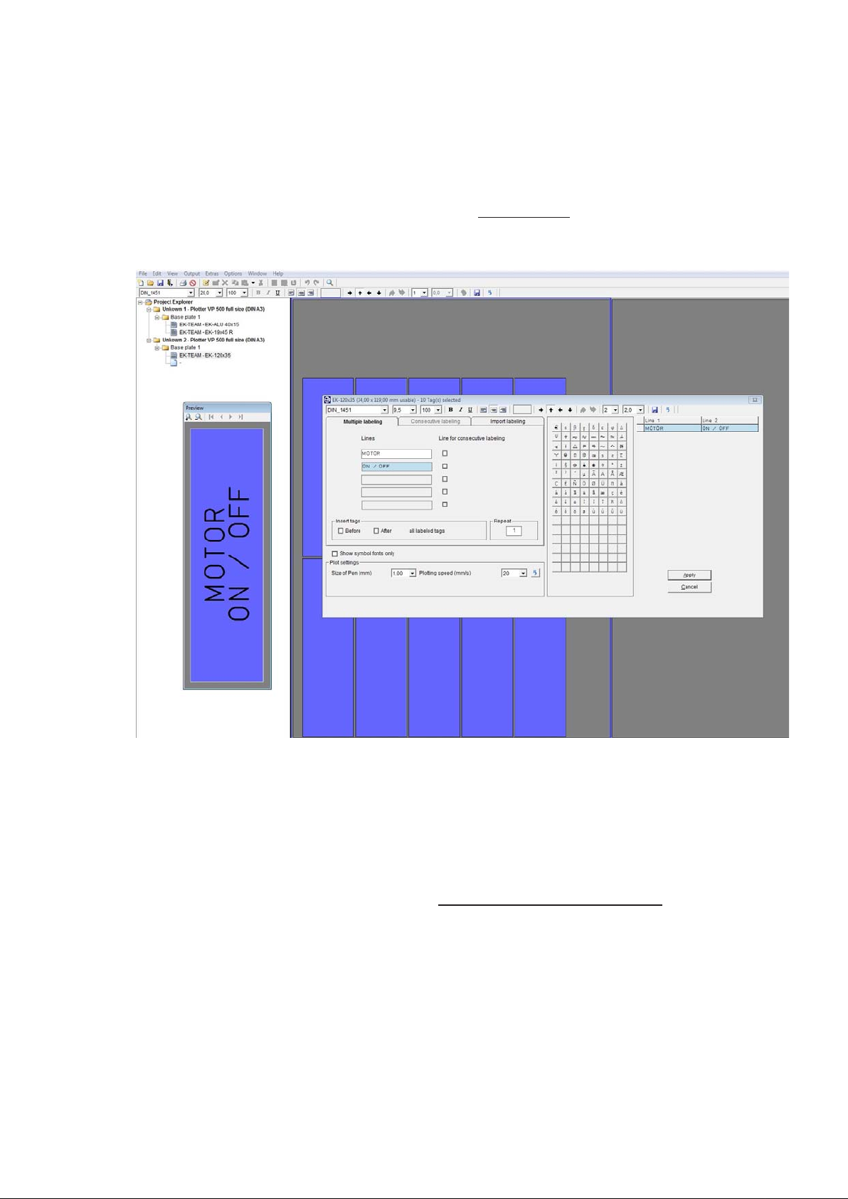
8.4.1 Multiple labeling
The relevant number of lines for editing will be opened according to the number of
lines set for each tag. You can now enter a suitable text and specify the number of
tags to be labeled with the same text in the > Repeat field. The entries are displayed in
the preview window. If required, you can also insert blank tags before or after the tags
you have labeled.
8.4.2 Consecutive labeling
If you need to number labels consecutively, you should first specify the number of lines
on the Consecutive labeling tab in which the consecutive numbering should be
inserted. To enable you to do this, the > Lines for consecutive labeling
field is activated
after the relevant lines.
After this, the program opens the consecutive labeling tab and the consecutive
labeling entries can then be added. You can enter the initial value, final value, text
prefix, text suffix, steps, counter and the number of repeats. You can opt for counting
to be ascending, i.e. the initial value is smaller than the final value, or descending,
i.e. the initial value is larger than the final value.
Page 18 of 67
Page 19
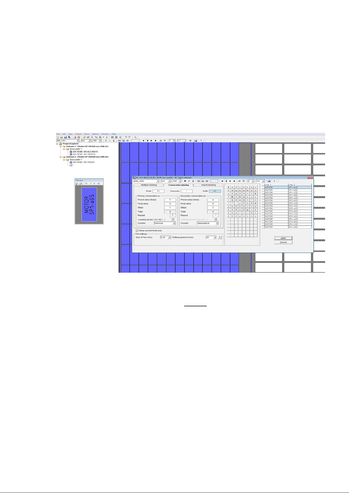
The window is split into two sections: primary consecutive number and secondary
consecutive number. This enables you to create two consecutive numbers that are
linked to one another. You can choose whatever you like as a separator.
The example shows the primary range TP 1 to 5 and the secondary
range 10 to 15-H, - has been selected as the separator, TP is thus the prefix text
and –H is the suffix text. The entries are displayed in the preview window.
When you click on the Apply button, the program takes you back to the previous tab.
If necessary, you can now add blank tags in front of each labeled tag. Likewise, you
can specify the number of series in the > Repeat
field in the Multiple labeling tab.
Page 19 of 67
Page 20
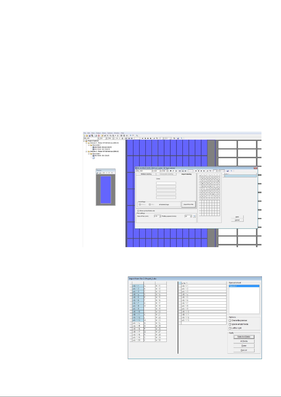
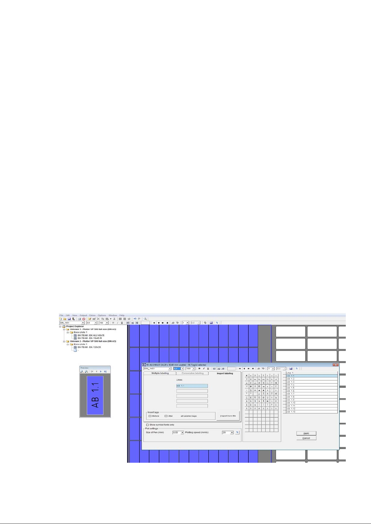
8.4.3 Importing labeling data from files
If you click on the Import labeling tab, you can import data from files.
You can copy data from programs such as E-plan, from text files or from
spreadsheet programs.
For a fast and easy way, you can copy and paste data through the clipboard.
A more efficient transfer help tool is available to do this, which enables you to extract
data from various file formats.
Click on the Import from file button to search for the file to be imported, then select it
by clicking on the file name and finally click Open to prepare the file for importing.
A window opens up and the file
to be imported is entered into a
table.
Page 20 of 67
Page 21
In this example, an Excel file was chosen. You can now select certain fields, sections
or individual cells and copy the selected data by clicking on the Selected fields
button. You can also copy all the data from the file by clicking on the All fields button.
Various options are available for importing:
- Overwrite preview
You have already imported data you do not want to use, just check the box
> Overwrite preview < and take the new selected data as new, this will overwrite the
existing data.
- Ignore empty fields
In case your spreadsheet file contains empty fields you do not want to import, just
check the box Ignore empty fields and they will be left out.
- Left to right
If you have selected 2 lines for the tag to be labeled, you can import the data e.g. from
Excel in a way that the orientation is correct from the beginning, in order to do so,
check the box > Left to right < and select two columns in the spreadsheet, when
importing.
When you have finished copying, click on the Apply button.
This will close the window and the data will be displayed in the previous window.
Page 21 of 67
Page 22

Note:
If you are importing data from text files, the data is not usually in a format available for
use. Various separators are available to enable you to separate the data properly.
You can use individual separators, or a combination of separators, such as Tab,
Space, Comma or Semicolon. You can also use other characters or letters. You can
activate this functionality by checking the < Other > box and then specifying your
requirement in the subsequent field, e.g. the letter B. Enter B in the empty field and
confirm your entry by clicking on OK.
Another option for separating when importing is to enter the number of characters.
Select < Fixed text length > and enter the number of characters after which a field
separation should be inserted, e.g. 4. Enter 4 in the empty field and confirm your entry
by clicking on OK.
If you want to import an Excel, Access or E-plan file, the program automatically
recognizes the type of file it is dealing with and provides the first table or worksheet
to be copied. You have the option of selecting additional worksheets or tables for this
file. The first worksheet or the first table are displayed by default.
Page 22 of 67
Page 23

8.5 Insert graphical elements or pictures
If you have selected an office printer or thermal transfer printer for printing the labels,
you can place as well graphics or pictures with the format JPEG, Bitmap or GIFF.
Highlight the label and select from the main menu > Edit
> Insert picture or click on the
icon insert graphic or picture.
Browse for the graphical element you want to insert and confirm with OPEN.
The element will be shown on all endless labels and on all labels of the sheets.
If you have used the layout function for dividing the label into text fields prior to placing
the graphical element, each text field can also hold a graphical element.
In addition the graphical element can be rotated in 90° steps.
To delete the graphic or picture click on the respective icon or go from the main menu
to > Edit
> Delete picture.
Page 23 of 67
Page 24

9. Output of labeling data
After entering all labeling data, the labeled tags can be printed or engraved. When you
began working, you selected the printing or engraving device you wanted to use.
If you click on the Print icon, the relevant printing output window opens for the output
device being used.
9.1 Output on plotter
The settings and information are entered or are displayed on the tabs.
Plot options – Support plates
Plot options tab
This tab enables you to set the following parameters:
- Only use pen inserted in pen holder
If you check this box, no pen is taken
out of the pen depot. Only the pen
inserted directly in the pen holder will be
used. This option is therefore always
required if you need to use pens that
are not suitable for the plotter’s pen
depot.
- Priming on pen change
If you select priming on pen change,
prior to labeling, the pen is taken to the
respective priming disk next to the pen
depot and is primed so that labeling is clear right from the first tag.
- Choose different pen in the pen depot
Two or more pens are displayed that should be used for this print instruction. If you
just want to use one plotter pen thickness, click on this option and choose the pen
to be used from the selection that subsequently appears.
- Choose plotting speed to be used
You can set different speeds for individual labeling sequences. If you just want to use
one speed, click on this option and set your required plotting speed from the selection
that subsequently appears.
Page 24 of 67
Page 25

- Pen size for graphic elements
You have the option of creating layouts on tags. These functions are detailed in the
section entitled > Create layouts on tags <. This enables you for example to create
text fields with frames, borders, etc. You can specify a particular pen for these graphic
elements.
- Plot speed for graphic elements
This enables you to select a particular plot speed for drawing graphic elements.
- Selected text will be printed
If you select this option, only the text you have previously selected will be printed.
- All selected tags will be printed
If you select this option, only the tags you have previously selected will be printed.
- All selected segments will be printed
With this option, only previously selected segments will be printed. You make your
selection by clicking on one or more segments on screen. You can select more than
one segment by holding down the Control key whilst clicking on the various
segments you wish to select.
Note:
If you are using the Plotter Basic half size (DIN A4) as the output device, some
options are not available for selection since this plotter has no pen depot and no
priming disk.
Support plates tab
This shows which labeling elements are being used and checks whether the
relevant support plate has been fitted
for the plotter. If a support plate is
missing or if the support plate is not
compatible with the labeling element,
the corresponding segment is
highlighted in red.
Note:
The Plotter Basic half size (DIN A4) has no support plate recognition and therefore
no check can be made to ensure the correct support plates have been fitted.
Page 25 of 67
Page 26

9.2 Output on engraver
The settings and information are entered or are displayed on the tabs.
Engraving options – Tag contours – Support plates
Engraving options tab
Within the upper part of the window under text and symbols you can enter couple of
settings.
When entering labeling data, various
engraving parameter will be pre-set
depending on the font size and
material. The labeling window displays
the depth of the engraving tool, the
engraving speed, the RPM for the
engraving spindle and penetration speed
used for each labeling task. If
necessary, you can change
the various settings as detailed below.
- Only one engraving tool and depth to be used
By entering the engraving data various engraving needle sizes will be assigned by the
program, depending on the font size. In the right side of the window the proposed
needle sizes are displayed. When executing the job, the system stops after the first
part with the first needle is finished, asking for exchanging the needle to the proposed
second size.
Click this option if you only want to use one tool size and depth of penetration.
- Only one engraving speed to be used
Different engraving speeds can be set for individual labeling tasks. If you just want to
use one speed, click on this option and set your required engraving speed from the
selection that subsequently appears.
- Choose RPM to be used
You can set different RPMs for the engraving spindle for individual labeling tasks. If
you just want to use one spindle speed, click on this option and set the spindle
speed required (RPM) from the selection that subsequently appears.
Page 26 of 67
Page 27

- Only one penetration speed to be used
You can set different speeds for individual labeling sequences. If you just want to use
one speed, click on this option and set your required penetration speed from the
selection that subsequently appears.
- Speed for graphic elements
You have the option of creating layouts on tags. These functions are detailed in the
section entitled > Create layouts on tags <. This enables you for example to create
text fields with frames, borders, etc. For these graphic elements, you can set the
parameters for the engraving speed, RPM for the engraving tool, and the penetration
speed for the engraving tool into the material being engraved.
The parameters are pre-set as factory default.
- Selected text will be engraved
If you select this option, only the text you have previously selected will be engraved.
- All selected tags will be engraved
If you select this option, only the tags you have previously selected will be engraved.
- All selected segments will be engraved
With this option, only previously selected segments will be engraved. You make your
selection by clicking on one or more segments on screen. You can select more than
one segment by holding down the Control key whilst clicking on the various
segments you wish to select..
- Engrave tag contour
If you check this box, the program automatically takes you to the Tag contours tab.
You can then use this tab to set
parameters according to whether you
wish to engrave tag contours, i.e.
outlines and any necessary holes. This
option is used if, for example, you are
using blank engraving plates or tags
that have not been prefabricated.
- Engrave contour around tags with lettering only
If you check this box, a frame will only be engraved around the tag if it contains
lettering.
- Engrave contours around all tags
If you select this option, a frame will be engraved around all tags.
Page 27 of 67
Page 28

- Round frame corners
If you select this option, a combo box appears in which you can set the radius to the
corners. You can set radii from 1 mm to 5 mm, graduated in steps of .5mm.
- Engrave holes on tags with lettering only
If you select this function, holes, if designed, will be engraved only on tags containing
lettering.
- Engrave holes on all tags
If you select this option, holes, if designed, will be engraved on all tags.
- Test plot
If you select this option you can test the engraving design using a pen before starting
the engraving job.
Note:
For making the test plot a special adapter, available as option, is needed in order to
hold the pen in place for plotting, inserted into the engraving head.
This feature is supported by the dedicated engraver only.
- Engrave tag contour only
Checking this box will enable you to just engrave the tag contours.
- Speed for tag contour
You can use this section to set the engraving speed, the revolution speed (RPM) of the
engraving spindle and the penetration speed for the engraving spindle for the material
being engraved. The parameters are pre-set as factory default
Note:
In principle, lettering is always engraved first, followed by the contours, as long as the
relevant parameters have been set.
- Setting the engraving material thickness
At the right side of the window you need to set the material thickness, if not already
displayed. Click on the combo box and select the material accordingly.
Note in general:
All in green indicated letterings and graphical elements such as holes, frames etc. will
be engraved according to your settings done.
Page 28 of 67
Page 29

Support plates tab
This shows which labeling elements are
being used and checks whether the
relevant support plate has been fitted
for the engraver. If a support plate is
missing or if the support plate is not
compatible with the labeling element,
the corresponding segment is
highlighted in red.
Note:
The Plotter Basic half size (DIN A4) with
engraving option and dedicated
Engraver series have no support plate
recognition and therefore no check can be made to ensure the correct support plates
have been fitted.
After all settings made the click on the OK button starts the engraving in general and
the following window opens:
The following sequence for engraving
will be done:
At the beginning all letterings, symbols then
after graphical elements followed by
contours will be engraved, if set
accordingly.
The top part of the window indicates the
respective engraving to be done,
letterings or symbols, graphical
elements, contours.
The right side the selected needle size is
indicated for you to follow or not.
The middle part provides information about the requested needle size and engraving
depth.
With a click on the Start button, the engraving will be started, right after three
additional buttons Repeat, Stop, Continue appear on the screen.
Page 29 of 67
Page 30

The button Stop will interrupt the engraving immediately and the engraving head
returns to the home position.
With the button Repeat the current engraving part can be restarted.
With the engraving part completed the button Continue takes you to the next step of
the engraving sequence, like graphical elements or contours if set up.
If no further steps are set the button
Continue is closing the engraving
window.
9.3 Printing on an office printer
The first time you send your data to be printed on an office printer, the following
message appears on screen:
When you confirm the message by clicking on OK, a window opens with the Printer
tab showing all printers available.
Page 30 of 67
Page 31

Now choose the printer you require and click on the button Test page.
A < Portrait test page > sheet is then printed on the relevant printer. Measure the top
and left margin with a ruler and enter the values in the respective boxes.
These entries are needed because all printers have different margin settings for text.
Click on OK to save these values. The program will then take you to the
< Print options > window, where you can set the following parameters for the printout:
- Specify the number of label sheets to be printed.
- Specify whether only the selected text or labels (tags) should be printed.
- Specify whether a frame should be printed around the lettering.
This function is useful if you want to cut out printed labels with scissors.
If you check this box, the program automatically takes you to the frame selection.
By clicking the relevant box, you can choose whether to plot a frame around labels
with lettering only or to plot a frame around all labels on the sheet.
If you select Plot frame only, only the frames will be printed, without any lettering.
Page 31 of 67
Page 32

9.4 Printing on a thermo transfer printer
The first time you send your data to be printed on a thermo transfer printer, the
following message appears on screen:
When you confirm the message by clicking on OK, a window opens with the Printer
tab showing all printers available.
Now select the TT printer required.
The < Increase size of tag> setting enables you to adjust lengths for unlimited strips
(Scale factor).
Page 32 of 67
Page 33

Click on OK to save these settings. The program will then take you to the
Print options window, where you can set the following parameters for the
printout:
- Enter the distance from left margin of the printing area.
- Specify whether only the selected text or labels (tags) should be printed.
By clicking on the tab Strip options you can modify the strip output.
- Increase size of tags to compensate width of terminal blocks
With the change of the value the width of the sections of the strip can be increased or
decreased to match the tag size.
- Raster mark showing as
Selecting, if raster mark should be printed, either All after each segment, Last only at
the end of last segment or None.
- Raster mark
- Selecting, if raster mark should be printed as Line or Dot.
- Specify whether only the selected text or labels (tags) should be printed.
Page 33 of 67
Page 34

10. Create layouts on tags
If you want to arrange text fields or graphic elements on tags, the program has a
user-friendly layout option that you can use for this purpose. This function is helpful
when you want to divide a tag into various fields. It gives you the opportunity to use
various font styles, font sizes and symbols in the individually created text fields. This
function is also useful if you want to create individual labeling fields on prefabricated
rating plates.
Call up the element for which you need to create a layout, select a tag and select
> Edit tag layout from the drop-down menu
.
Page 34 of 67
Page 35

After choosing the layout, the following window appears on screen.
The tag size is displayed in the top left field of the window.
Underneath that, you will see various components available that you can set up on the
tag.
For example, if you want to create a < text field with frame >, click on the
relevant component. You should then use the mouse to position the cursor in the
right-hand side of the window in the tag displayed there, click with the mouse to
specify where the text field should begin, and use the mouse to define the text field.
This will create your text field.
For other selections proceed the same way. You can also place circle / ellipse,
square / rectangle or separator lines on the tag.
Now you can click on the text field and move it to wherever you want it. You can also
enter the coordinates, such as the distance from the margin, height and width of tag,
directly into the relevant fields and confirm by pressing Enter. The entry is immediately
applied and the preview is updated.
Note:
It is easy to inadvertently move the graphic elements you have created when you
click on them with the mouse. In order to avoid moving the elements in error, you can
fix their positions by calling up the drop-down menu.
After fixing the position, you can still change the size and position of graphic elements
by entering the coordinates directly into the relevant fields.
Page 35 of 67
Page 36

If you are using a plotter or engraver as your output device, you can measure the text
fields with the plotter. To do this, click on the text field whose measurements you wish
to take and select >Take Measurement of text field function from the drop-down
menu.
The following window opens up:
Insert a pen directly into the
pen holder or take the spindle
out of the engraving head and
insert instead the optical
measurement tool, available as
option.
Then click on the left
Initial position button. The plotter
moves to upper left corner of the total
plot area. You can now go to the text
field in the top left-hand corner and
use the cursor keys to take the tip of
the pen or cross of the tool right to
the corner of the text field.
You can choose the step size for each click of the cursor button.
Once you have defined the upper left corner, go to the lower right corner of the text
field by clicking on the second Initial position button. Proceed as before. When you
click on Apply, the coordinates will be applied.
You can duplicate or delete components that have been created.
You also have options available for setting the alignment of text fields or graphic
elements that have been set up.
If, as shown in the example, you have used the mouse to click on the three
components whilst holding down the Control key and then clicked on the Vertical
alignment button, the elements created are aligned vertically. Other layout options are
available.
You can alter the size of the preview window to make it larger or smaller.
Page 36 of 67
Page 37

Once the layout is completely finished, there are two options available for you to apply
the layout:
Click on the Apply button to apply the layout to the previously selected tags. You can
now enter labeling data straight into the fields.
If you want to save this layout on the tags, click on the Save as button.
You then need to save this tag with the layout you have created with a new name.
When you want to use this labeling element with the layout at a later date, you can call
up the labeling element in the > User defined < folder.
Page 37 of 67
Page 38

11. Designer / Layouter
This is used for setting up your own marking elements, label sheets, endless labels or
endless strips, engraving tags or rating plates for engraving.
There are 4 different versions of the Designer/Layouter.
These can be selected on the menu by clicking on > Extras
> Tags and strips (Plotter)
> Tags (Engraver)
> Label sheets (Office printer)
> Endless labels and strips (Thermo transfer printer)
11.1 Setting up marking tags and strips for plotters
The Designer is called up using the following menu item:
> Extras > Designer/Layouter for > Tags and strips (Plotter).
> Designer / Layouter for
The following window opens up:
Here you can create a new
marking element by clicking
on the New button.
First enter the name of the
marking element you wish to
create in the left-hand window.
Next, you have to make the
following settings:
Use the plotter's support plate
recognition function.
If you have a plotter with support plate recognition, it is advisable to use this function
to make it easier later on to find the marking element that you have created. To do this,
the plotter must be switched on and the relevant support plate positioned on the
plotter.
If you do not want to use support plate recognition, or are using a plotter with no
support plate recognition function, click on Specify type of support plate.
Now you have to select the support plate on which you want to set up the tag or
element.
In the next stage you define the properties of the marking element.
Page 38 of 67
Page 39

Here you can choose between three options:
- Design tags within single group
The marking element has only one tag size.
- Design tags within multiple groups
The marking element has two or more tag sizes.
- Design strips
With this function you can create marking strips with the size needed, dividing them
into horizontal and vertical sections.
Selecting one of the dividing directions opens another window for entering the
additional strip parameter.
Page 39 of 67
Page 40

11.1.1 Design a marking element with one tag group
Enter the tag parameters for the marking element.
If you do not have the exact data to hand, it is easy to use the plotter to measure the
tags (recommended).
To measure using the plotter, all
you have to enter is the number
of tags along the X- and Y-axes.
All the other data can be easily
calculated using the program
and with the help of the plotter.
You can also specify the
sequence in which the tags will
be labeled. The sequence for
labeling can either be from
Upper left > to Upper right (line
by line), or from Upper left > to
Lower left (column by column).
Attention:
For processing to continue, it is essential that the plotter is switched on and the
marking element which is to be set up is positioned on the plotter, with the appropriate
support plate. Insert a pen directly into the plotter's pen holder. As an option, there is
also an optical measuring tool available which you can use to calculate and specify the
tag parameters. This tool is inserted like a pen directly into the plotter's pen holder.
When you have entered all or just some of the tag parameters, but at least the number
of tags along the X- and Y-axes, click on the Take measurements button and the
following window opens up:
To take measurements, proceed as follows:
First of all, specify the exact
position of the upper left corner
of the first tag in the matrix. To
do this, click on the
Initial position button left in the
first tag window. The plotter's
writing arm now moves to the
upper left corner of the plotter
field. You can use the relevant
cursor buttons as shown to
move to the exact position of the upper left corner of the first tag.
Page 40 of 67
Page 41

You can choose the step size for each click of the cursor at the top right of the
window. When you have moved to the position for the corner, you can use the
Pen Up/Down button to check that you have reached the exact position. The relevant
coordinates are displayed in mm, from the starting position of zero. Now specify the
exact position of the lower right corner for the first tag.
Do this following the same procedure as detailed above for locating the upper left
corner.
Now specify the upper left corner of the last tag in this matrix.
Go to the last tag bottom right and proceed just as before.
Specifying these three points completes all measurements for this marking element.
You can now save the values you have calculated by clicking on the Apply button.
The < Take measurements > window is closed and the program takes you back to
the previous page.
If you also click on the Apply button here, you will see the marking element that has
been set up. You can now check that all data have been correctly calculated. If any
error messages or notices are displayed, you should check your data again or allow
automatic correction.
Having completed the marking element, you now also have the option of positioning
text fields and graphic elements on the tags. Creating text fields like this is always
useful if you want to divide the tag up into different fields, so that you can later use
different text sizes, font types or symbols on the tag. See Section 10 of this manual for
information on how to set up a layout.
After you have specified the design and, if you wish, also the layout, click on Back to
close the Designer or Layouter.
The program takes you back to the main window, which you can then close by clicking
on the Close button.
You can select the labeling element you have created in the folder
>User defined
under > Manufacturer and call it up for lettering.
Page 41 of 67
Page 42

11.1.2 Design a marking element with more than one tag group
To set up groups of tags of different sizes, you proceed exactly as described in the
previous section.
In order to assign the tag groups, on the left of the window you must specify
appropriate names for the different tag groups. Once you have specified the name for
a tag group, you can then
enter the tag parameters
and measure the tags and
then create a layout if
required.
When you have finished
one tag group, you can set
up more tag groups.
11.1.3 Design marking strips
You have already specified the name for the marking strip, X-strip.
Page 42 of 67
Page 43

The next thing to do is to define the strip parameters:
First select the alignment of the strip. Lay the strip(s) vertically or horizontally on the
plotter.
Then enter the length and width of the strip, followed by the number of strips lying on
the plotter.
By using the Take measurements function, it is easy to calculate the start coordinates
and the strip spacing. Proceed exactly as described in the previous section.
After you have measured the strips and pressed Apply, you can specify a layout for
the strips in the right-hand section of the window.
You can subdivide the individual strips using horizontal and vertical scale factors.
First, if required, divide the strips into horizontal sections.
First define the height of the first section, by entering the height in mm in the
> Partition 1
field. The remaining height is then transferred into > Partition 2. In this
way, you can subdivide the strips into a maximum of 5 sections. When you have
finished dividing them up into sections, first click on the Apply button. This completes
the horizontal subdivision.
Next, you can make a vertical subdivision for each section. Click on Crosswise for the
relevant strip.
Then the following window opens up:
To enter the required subdivision of the strip, proceed as
follows:
First enter the width and then the number of tags.
By clicking on the Add button, the data are transferred to the
field below. If the strip is not yet fully divided up, you will be
shown the length of strip that is still available. Now you can
specify other tag widths.
When you click on Apply, the program takes you back to the
previous window and displays the subdivision that you have
specified.
In this way you can subdivide the individual sections using
different tag widths in succession as required.
Page 43 of 67
Page 44

When you have finished all the subdivisions, close the Designer.
You can select the labeling element you have created in the folder
> User defined
under > Manufacturer and call it up for labeling.
Note:
If you have created the labeling data for a strip and are producing the plotting data on
the plotter, there is the opportunity to define various options for plotting.
On the tab Strip options, you can determine whether cutting marks as
separating lines or dots should also be plotted.
Page 44 of 67
Page 45

11.2 Setting up engraving tags for engraving units
Call up the Designer under > Extras > Designer/Layouter for > Tags (Engraver).
The following window opens up:
Here you can create a new
engraving element (individual
tags or tag groups) by clicking
on the New button.
First enter the name of the
engraving element you wish
to create in the left-hand
window.
Then you can define whether
you want to use the plotter`s
support plate recognition
function.
Use the plotter`s support plate recognition function.
If you have a plotter unit with support plate recognition, it is advisable to use this
function to make it easier later on to find the engraving element that you have created.
To do this, the plotter must be switched on and the relevant support plate positioned
on the plotter.
If you do not want to use support plate recognition, or are using a plotter with no
support plate recognition function, click on < Specify type of support plate >.
Pre-select is the DIN A4 support plate, select another type on which you want to set up
the element if required.
If none of the suggested support plates are required, click on
< Use complete labeling area >, also needed with the use of custom made support
plates.
Then you define the engraving material and enter the thickness of the material in the
box at the bottom of the window.
Page 45 of 67
Page 46

In the next stage you define the properties of the marking element.
Here you can choose between three options:
- Design tags within single group
The engraving element has only one tag size.
- Design tags within multiple groups
The engraving element has two or more tag sizes.
- Design strips
With this function you can create marking strips with the size needed, dividing them
into horizontal and vertical sections.
Selecting one of the three options opens another
window for entering the additional parameter.
Page 46 of 67
Page 47

11.2.1 Design tags within single group
Now there are various ways you can create your engraving tags.
- You want to create prefabricated sign / rating plate
First define the shape of the tag, square/rectangle or circle/ellipse.
Then enter the required tag size.
When you click on the Apply button, the tag you have created will be displayed.
If you like to create single text fields e.g. on a rating plate, click on the button
Create layout for text and graphic.
Details you can find in section 10.
With a click on the button Back takes you back to the previous window where you can
add additional tags or the button Close will exit the designer.
You can select the labeling element you have created for engraving in the folder
> User defined
under > Manufacturer and call it up for labeling.
Page 47 of 67
Page 48

- You want to create your tags on a blank plate.
First define the shape of the tag, square/rectangle, circle/ellipse, push button.
Then enter the required tag size and the number of tags in X and Y direction, or
click on < Automatic tag partitioning >.
When you click on the Apply button, the tags you have created will be displayed.
The program calculates the possible number of tags to be created on the selected
field. In case you enter the number of tags in X and Y direction manually and click the
Apply button, the tags will be displayed as well, any error will be indicated for you in
order to reduce the number of tags if the number in either direction do not match.
IN addition you can enter the start position and the distance between the tags,
You can also specify the sequence in which the tags will be labeled. The sequence for
labeling can be either from upper left > to upper right (line by line), or from upper left
> to lower left (column by column).
Having completed the engraving tags, you now also have the option of positioning
text fields and graphic elements on the tags. Creating text fields like this is always
useful if you want to divide the tag up into different fields, so that you can later produce
different text sizes, font types or symbols on the tag.
To do this, click on the Layout for text and graphics button.
See section 10 of this manual for a description of how to set up a layout.
If you now want to make holes or cutouts in the tags you have created, or round off the
corners, click on the Holes, cut-outs, frame corners button see below details.
You want to enter the data for an existing tag plate, please proceed as described
above. The exact position you can define using the take measurement function.
When you have entered all or just some of the tag parameters, but at least the number
of tags along the X and Y axes, click on the Take measurements button and the
following window opens up:
Page 48 of 67
Page 49

Attention:
For processing to continue, it is essential that the engraver is switched on and the
engraving element which is to be set up is positioned on the engraver, with the
appropriate support plate. First take the engraving spindle out of the engraving head
and then insert the optical measuring tool into the engraving head, available as an
option.
To take measurements, proceed as follows:
First of all, specify the exact position of the upper left corner of the first tag in the
matrix. To do this, click on the Initial position button left in the first tag window.
The engraver's engraving arm now moves to the upper left corner of the engraving
field. You can use the relevant cursor buttons as shown to move to the exact position
of the upper left corner for the first tag.
You can choose the step size for each click of the cursor at the top right of the
window. Go to the exact position of the top corner. The relevant coordinates are
displayed in mm, from the starting position of zero. Now specify the exact position of
the lower right corner for the first tag.
Now specify the upper left corner of the last tag in this matrix. Go to the last tag bottom
right and proceed just as before.
Specifying these three points completes all measurements for this engraving element.
You can now save the values you have calculated by clicking on the Apply button.
The < Take measurements > window is closed and the program takes you back to
the previous page.
If you also click on the Apply button here, you will see the engraving element that has
been set up.
You can now check that all data have been correctly calculated. If any error messages
or notices are displayed, you should check your data again or allow automatic
correction. Now the engraving element is created.
After you have specified the design click on Back to close the window, in the main
window you can design additional tags or you can close by clicking on the Close
button.
You can select the engraving element you have created in the folder
> User defined under > Manufacturer and call it up for engraving.
Page 49 of 67
Page 50

- Holes, cut-outs, frame corners
If you now want to make holes or cut-outs in the tags you have created, or round off
the corners, click on the Holes, cut-outs, frame corners button.
The following window then opens up:
Here you can round off the corners by clicking on the > Round frame corners
field and selecting the radius.
You also have the option of making holes or cut outs in the tag.
You can choose from the following:
- holes in a circle or ellipse
- cut-outs rectangle or in a square
- holes with tabs or notches
- elongated holes
After selecting, go to the tag with the mouse and draw a circle or a cut-out.
When selecting holes with tabs or notches you can choose the number of tabs or
notches, used for switches, push-buttons etc.
Later you can use the coordinates to define the position and size of the circle or
cut-out exactly.
There are a number of alignment functions available.
Use the Apply button to save the data and close the window.
Page 50 of 67
Page 51

Having completed the engraving tags, you now also have the option of positioning text
fields and graphic elements on the tags. Creating text fields like this is always useful if
you want to divide the tag up into different fields, so that you can later produce
different text sizes, font types or symbols on the tag.
To do this, click on the Layout for text and graphics button.
See Section 10 of this manual for a description of how to set up a layout.
After you have specified the design and, if you wish, also the layout, click on Back to
close the Designer or Layouter.
The program takes you back to the main window, which you can then close by clicking
on the Close button.
You can select the engraving element you have created in the folder
> User defined under > Manufacturer and call it up for engraving
11.2.2 Design tags within multiple groups
To set up groups of tags of different sizes, you proceed exactly as described in the
previous section.
In order to assign the tag groups, on the left of the window you must specify
appropriate names for the different tag groups. Once you have specified the name for
a tag group, you can then enter the tag parameters and measure the tags and then, if
you wish, add holes, cut-outs and radii.
Then a layout can be created.
When you have finished one tag group, you can set up
more tag groups.
Page 51 of 67
Page 52

11.2.3 Design marking strips
You have already specified the name for the marking strip, “X-strip”.
The next thing to do is to define the strip parameters:
First select the alignment of the
strip,lay the strip(s) vertically or
horizontally on the engraver.
Then enter the length and width
of the strip, followed by the
number of strips lying on the
engraver.
By using the < Take measurements > function, it is easy to calculate the start
coordinates and the strip spacing.
Proceed exactly as described in the previous section.
After you have measured the strips and clicked on Apply, you can specify a layout for
the strips in the right-hand section of the window.
You can subdivide the individual strips using horizontal and vertical scale factors.
First, if required, divide the strips into horizontal sections.
First define the height of the first section, by entering the height in mm in the
> Partition 1
field. The remaining height is then transferred into > Partition 2. In this
way, you can subdivide the strips into a maximum of 5 sections.
When you have finished dividing them up into sections, first click on the Apply button.
This completes the horizontal subdivision.
Next, you can make a vertical subdivision for each section. Click on Crosswise for the
relevant strip.
Page 52 of 67
Page 53

Then the following window opens up:
To enter the required subdivision of the strip, proceed as
follows:
First enter the width and then the number of tags.
By clicking on the Add button, the data are transferred to the
field below. If the strip is not yet fully divided up, you will be
shown the length of strip that is still available. Now you can
specify other tag widths.
When you click on Apply, the program takes you back to the
previous window and displays the subdivision that you have
specified.
In this way you can subdivide the individual sections using
different tag widths in succession as required.
When you have finished all the subdivisions, close the
Designer.
You can select the labeling element you have created in the
folder
> User defined under > Manufacturer and call it up for labeling.
Note:
If you have created the labeling data for a strip and are producing the engraving data
on the engraver, the horizontal and vertical separating lines will be engraved.
Page 53 of 67
Page 54

11.3 Setting up label sheets for office printers
Call up the Designer under > Extras > Designer / Layouter for > Label sheets
(Office printer).
The following window opens up:
Here you can create a new label sheet by
clicking on the New button. First enter the
name of the label sheet you want to create in
the window.
Then click on Edit and another window opens:
Now you have to enter the appropriate tag
parameters for your label sheet here. If you
do not have the data directly to hand, then
you must enter the width and height of the
tag, the distance from the top left-hand
corner of the first tag (start coordinates) and
the tag spacing along the X- and Y-axes,
using a ruler. You also have to enter the
number of tags along the X- and Y-axes.
You can also specify the sequence in which
the tags are printed.
Page 54 of 67
Page 55

The sequence for labeling can be either from upper left > to upper right (line by line),
or from upper left > to lower left (column by column).
When you click on the Apply button, the tags you have created are displayed on the
screen.
Having completed the labels, you now also have the option of positioning text fields
and graphic elements on the labels. Creating text fields like this is always useful if you
want to divide the label up into different fields, so that you can later use different text
sizes, font types or symbols on the label.
To do this, click on the Create layout for text and graphic button.
See Section 10 of this manual for a description of how to set up a layout.
After you have specified the layout if you wish, click on Back to close the Layouter.
The program takes you back to the main window, which you can then close by clicking
on the Close button.
You can select the labeling element you have created in the folder
< User defined under > Manufacturer and call it up for printing.
11.4 Setting up endless labels and strips for thermo transfer printers
Call up the Designer under > Extras
> Designer for > Endless labels and strips
(Thermo transfer printer).
The following window opens up:
You can now create new endless labels or
endless strips here by clicking on the New
button.
First enter the name of the label or strip that you
want to create in the window.
Now you have to specify whether you want to
create an endless label or an endless strip.
Click on either Label or Strips.
After you click on one of those options, the
relevant window opens.
Page 55 of 67
Page 56

11.4.1 Design an endless label
Enter the width and height of the tag here.
If, on your endless roll, you have more than
one label side by side, enter the number of
labels in the appropriate field.
You must also enter the tag distance in X and Y.
Page 56 of 67
Page 57

Note:
When the labels are subsequently printed out on a thermo transfer printer, the tag
spacing along the Y-axis is detected by a light barrier. The entry on the tab only serves
to ensure that it displays correctly on the screen.
When you click on the Apply button, the tags you have created are displayed on the
screen.
Having completed the labels, you now also have the option of positioning text fields
and graphic elements on the labels. Creating text fields like this is always useful if you
want to divide the label up into different fields, so that you can later use different text
sizes, font types or symbols on the label.
To do this, click on the Create layout for text and graphic button.
See Section 10 of this manual for a description of how to set up a layout.
After you have specified the layout if you wish, click on Back to close the Layouter.
The program takes you back to the main window, which you can then close by clicking
on the Back button.
Click on Close to close the Designer.
You can select the labeling element you have created in the folder
< User defined under > Manufacturer and call it up for printing.
11.4.2 Design an endless strip
First decide on the size of the strip and enter its length and width.
Then you can divide up the strip using horizontal
and vertical scale factors.
If required, divide the strip into horizontal
sections.
First of all, specify the height of the first partition,
by entering the height in mm in the > Partition 1
field. The remaining height is then transferred into
> Partition 2. In this way you can subdivide the
strip into a maximum of 5 partitions.
Page 57 of 67
Page 58

When you have finished dividing the strip into partitions, you first click on the Apply
button. This completes the horizontal division.
After that, you can make a vertical division for each partition. Click on Crosswise for
the relevant strip.
Then the following window opens up:
To enter the required subdivision of the strip,
proceed as follows:
First enter the tag width and then the number of
tags.
By clicking on the Add button, the data is
transferred to the field below. If the strip is not yet
fully divided up, you will be shown the length of strip
that is still available. Now you can specify other tag
widths.
When you click on Apply, the program takes you
back to the previous window and displays the
subdivision that you have specified.
In this way you can subdivide the individual
partitions using different tag widths in succession
as required. When you have finished all the
subdivisions, close the Designer.
You can select the labeling element you have
created in the folder < User defined under >
Manufacturer and call it up for printing.
Note:
If you have created the labeling data for a strip and are printing out the print data on a
thermo transfer printer, there is the opportunity to define various options for printing.
You can determine whether dividing marks as separating lines or dots should also be
printed.
Page 58 of 67
Page 59

12. Import/Export of labeling elements and labels created with
various designer versions
Elements created by the user, as detailed in the preceding sections, can be imported
and exported. This provides an opportunity to swap elements that you have defined
yourself. To export a marking element, click on the Export button and then
select the location where the txt file should be saved. You are advised to use the
name of the element as the file name.
Exported files can be imported to another
workstation. To import, click on the
Import button and select the file to be
imported.
The new element appears in the list of
marking elements in the > User defined
folder.
If the database already contains an
element with the same name, the
element that already exists can be
overwritten.
13. Special functions using plotter and engraving versions
13.1 Access of graphic files for plotting or engraving
Graphic files, designed and created by e.g. CorelDraw, can be sent to the plotter or
engraver, assuming the files are saved as .plt file extension (HPGL).
If you like to send the file, please go to > Extras
menu.
The following window appears:
Clicking on Search you can browse through the folders selecting the file to be plotted.
Further settings can be changed:
- Priming on pen change, check click box
- Plotting speed, range 5 to 40 mm/sec
The file will be sent to the plotter by
confirming the selection with OK.
> Send HPGL file from the main
Page 59 of 67
Page 60

If you like to send the file to the engraver the following window appears:
Clicking on Search you can browse through the folders selecting the file to be
engraved.
Further settings can be changed:
- Engraving speed, range 2 to 20 mm/sec
- Revolution (RPM) spindle, range 5000 to 50000 RPM
- Penetration speed, range 2 to 6.5 mm/sec
The file will be sent to the engraver by confirming the selection with OK.
13.2 Scale factor
The data in the database have been carefully entered and checked. However, they are
not subject to regular checking. Thus over time, the tags to be printed could have their
mechanical measurements altered, particularly the scale, i.e. the distances of the
markers from one another in both the x- and y-directions.
Possible influences include workstation temperature and humidity.
However, production influences, such as materials and temperatures when making the
tags, could also have an impact such that there could be deviations from the original
values set. Deviations > 1 mm are quite possible across the entire length and width as
well as a shift in the start point.
In order to make any correction to possible deviations, select from the main menu
> Extras
> Shift of start point and correction of scale factor.
If you notice the output on the tag is not centered, you can change the start point and
the scale factor in x- and y-direction accordingly.
Page 60 of 67
Page 61

To make a correction, proceed as follows:
Turn on the plotter and select a tag on the segment and then follow the menu path
> Extras > Shift of start point and correction of scale factor.
The tags are now all colored red and the following window appears:
Insert a plotter pen into the pen holder or the optical measurement tool with hairline
cross into the engraving head (spindle location) and click on the button
Initial Position in the far left field.
The plotter moves to the upper left corner of the first tag. The peak of the
pen or hairline cross needs to match with the corner point.
In order to find the exact corner point you can move the plotter with the four cursor
buttons to the exact position; you can set the steps to be between .025 mm to 10 mm;
the default step value is .1 mm.
Then after click on the button Initial Position for the lower right corner of the first tag
and proceed the same way to match the peak of the plotter pen or hairline cross with
the lower right corner of the tag.
In order to find the exact corner point, you can move the plotter to the exact position
with the four cursor buttons.
Page 61 of 67
Page 62

Then click on the button Initial Position for the very last tag of the matrix bottom right,
the plotter moves to the beginning of the last tag, the upper left corner.
The peak of the pen or hairline cross needs to match with the corner point.
In order to find the exact corner point you can move the plotter with the four cursor
buttons to the exact position.
After making the amendment, you need to click the Apply button in order to apply the
data; the original database remains unchanged. Close the window and the plotter
goes back to its initial position.
You can return to the original settings at any time by clicking on the Reset button in
the window.
Note:
Any change of the scale factor can only be done this way for tags stored in the general
database, user designed tags can be changed by using the designer function.
Page 62 of 67
Page 63

13.3 Base plates and segments
The plotter has one base plate that can be fitted with various support plates. For this
reason, the base plate is divided into sections known as segments. An A3 plotter has
four segments and an A4 plotter has two segments. You can create several base
plates in one project. Follow the menu path > Edit
> Base plate > Add to add a new
base plate. The bottom line of the screen shows the base plates created. It is also
possible to copy base plates and segments.
The project explorer at the left side of the screen shows the current projects open and
base plates as well as segments used.
Segment 1
Segment 2
Segment 3
Segment 4
Base plate 1
13.4 Control print of the labeling data
If required, you can print the labels you have created on a base plate on a standard
office printer, for checking purposes.
You can run the print by following the menu path > Extras
> Print on paper printer.
Page 63 of 67
Page 64

13.5 Calibrating plotter versions
There is usually no need to calibrate the plotter, as all devices are calibrated at the
plant. However, if small deviations occur when printing (labeling is not properly
centered on the tag), there is an option to make small adjustments using manual
calibration. In order to reposition lettering, proceed as follows:
Note:
Make sure that the plotter’s writing arm is able to move freely and that there are
no obstructions, such as a ballpoint pen, on the plotting surface. Follow the menu path
> Output
> Special features Plotter / Engraver. The Calibration tab will appear.
The writing arm moves to a preset
starting position and four cursor
buttons appear in the menu for you to
press in order to move the plotter's
writing arm.
The step size can be changed within a
range of .025 mm to 10 mm. The default
step size is set at .1 mm.
Reposition by moving to the right or to
the left, up or down, by clicking on the
relevant cursor buttons.
Each click of the cursor button will move the writing arm by the step distance, in this
case .1mm.
After completing the adjustment, you need to click on the Calibrate button in order to
apply the new data. After you have successfully completed calibration, close the
window.
You can repeat this step as many times as you like until you achieve an optimum
output.
Click on the Reset button to go back to the original settings.
Check the position always on the upper left tag
(see > Extras
> Shift of start point and correction of scale factor).
Page 64 of 67
Page 65

13.6 Assigning the support plate to the marking element
The database for the labeling software contains a large number of marking elements
from different manufacturers. Each marking element is assigned to particular support
plates.
The menu item > Help
with which support plates. There is a wide range of search functions available for
doing this. For example, you can search for a particular marking element and find the
relevant support plate, etc.
> Support plates shows which marking elements can be used
14. General information and adjustments
14.1 Zoom function
You can activate and deactivate the zoom function by following the menu path
> View > Zoom function or by clicking on the relevant icon. Click once on the icon and
then take the mouse to the point on the base plate whose view you wish to change.
Left-click with the mouse to select this point as the new central point of the screen
and enlarge the display. Clicking the icon again deactivates the function, thus
enabling you to continue working with the zoom factor that you have now set.
Right-click with the mouse to reduce the size of the screen content.
14.2 Select program language
You can change the program language by following the menu path
> Options
14.3 Display and switching within open project files
You can always obtain an overview of the number of projects and base plates open
from the > Window
many as 10 projects, with each project having up to 256 base plates (plotter and
engraver). You can use this menu to switch from one project to another.
> Language settings.
menu or looking at the explorer view to the left. You can work on as
Page 65 of 67
Page 66

14.4 Standard font type
You can specify a standard font for the different output devices.
By using the menu > Options > Standard font, you can select the font type that you
would like to use as standard for a particular output device.
If you have selected a marking element for labeling, the standard font type is
preset.
If you change the font type, then in
future the font type that you last
selected will be retained when you
use that marking element.
14.5 Standard pen sizes
Up to four different pen sizes (line thicknesses) can be used in the pen depot on the
Plotter full size (DIN A3) and Plotter half size (DIN A4).
The following configuration is preset: Position 1: .18 mm, Position 2: .25 mm,
Position 3: .35 mm and Position 4: .50 mm.
You can change these settings using the menu item
> Options
> select standard pen sizes.
Click on the pen sizes to determine which pen sizes should be used as standard.
Page 66 of 67
Page 67

14.6 Software version
Follow the menu path > Help > Info, to find out which version of software for the
labeling program is installed and the database status.
14.7 Check for updates
Follow the menu path > Help > Check for updates, to find out if there would be an
update of the software available. In order to retrieve the information, you need to be
connected to the internet and allow the firewall to access our web server. In case of an
update availability, you will receive an information on the screen to contact your local
sales representative.
14.8 Online help
Follow the menu path > Help
> Manual or use function key F1 to open the software
manual on the screen.
Page 67 of 67
 Loading...