

Page 1

=
=
Electrical: at rated load: > 1,5 x 1 0
5
cycles.
Mechanical: > 15 x 10
6
cycles
=
=
=
CONTA-ELECTRONICS
=====
=====IIIIsolated
solated S
==========
solatedsolated
Electrical specifications
Electrical specifications
Electrical specificationsElectrical specifications
=
Order in formati on
Order in formati on
Order in formati onOrder in formati on
type CMS-UI-R
cat.no 95120.8
Input da ta
Input da ta
Input da taInput da ta
range (select via dipswitches) 0-1V/0-2V/0-2,5V/ 0-5V/1-5V/0-10V/0-20V/0 -40V/0-5mA/0-10mA/0-20mA/4-20mA
max. input signal (U / I) 40V / 25mA
input resistance (U / I) > 200 kOhm / 50 Ohm
Output da ta
Output da ta
Output da taOu tput data
relay output 1CO contact, 240V~
output function (select via dipswitch) threshold with hysteresis / ON and OFF threshold / threshold r ange control
adjustment range Threshold / Hysteresis 10…90%
rated / inrush current (ohmic load) 3A / 5A
max. power rating 1200VA @ 240V ac, 5A
life span @ 23°C and ohmic load
contact material AgNi
test voltage 4kV
General data
General data
General dataGeneral data
module power supply 24V DC ±25%
module current Approx. 50mA
temperature coefficient < 0,02 %/°C
max. conversion frequency 10Hz
CE marking Low Voltage Directive (LVD) 2006/95/EC, accordi ng requirements of EN 61010
isolation voltage input / power 1kV, 50Hz, 1min.
isolation voltage input / output 4kV
isolation voltage output / power 4kV
operating / storage temperature 0°C…+55°C / -20°C…+70°C
conductor cross section 0,2 - 2,5 mm²
connection system screw clamp connection, pluggable
insulation stripping length 7 mm
mounting / installation position DIN-rail TS35 / any
module size LxWxH (TS35) 17,5 x 99 x 114,5m m
weight 120 gr
Signal
ignal converter
ignalignal
converter
converterconverter
S S
EMC Directive 2004/108/EC, accord ing requirements of EN 55011 and EN 61326-1
===== = = = = = = = = =
Manual
Manual
ManualManual
=
=
Features:
Features:
Features:Features:
• Multifunctional analog input (0..1V, 0..2V, 0..2,5V, 0..5V, 1..5V, 0..10V, 0..20V,
0..40V, 0..5mA, 0..10mA, 0..20mA, 4..20mA)
• 3 output relay control functions (threshold with hysteresis, ON and OFF threshold,
threshold range control)
• Analog signal range selectable via DIP switches
• 3-Way galvanic isolation
• Power supply 24V DC
• Other analog signal ranges on request
=
The CMS-UI-R is a multi-functional 3-way isolated
threshold relay. This module is used for control and
alarm functions.
The 3-way isolation enables the module to be used
locally as well as in the vicinity of the controlling
system.
The inputs and output relay functions of the converter
are configured by means of dipswitches.
Any combination of input and output can be chosen,
so numerous different control functions can be set.
Default input/output relay setting is 0..10V / threshold
with hysteresis.
=
Other default input/output settings on request.=
CMS
CMS----UI
UI----RRRR=
CMSCMS
UIUI
Cms-ui-r manual rev0.fl.doc
Further information: www.conta-clip.com Cat. No.: 95120.8
Further information: www.conta-clip.com
Page 2
CONTA-ELECTRONICS
=====
=====IIIIsolated
solated S
==========
solatedsolated
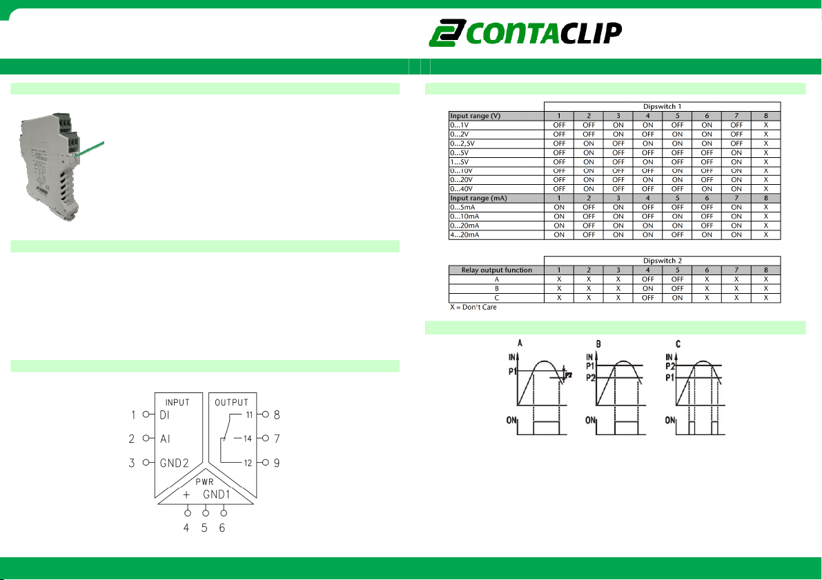
Configuration
Configuration Dipswitch settings
ConfigurationConfiguration
=
=
Connecting the module
Connecting the module
Connecting the moduleConnecting the module
=
The pin configuration for I/O and power connection is shown on the top of the module.
DI input is not used.
Signal
ignal converter
ignalignal
converter
converterconverter
To open the module press the locking levers under the
terminals with a screwdriver.
The module is configured by setting the dip-switches according
to this manual and the table on the side of the module.
=
=
=
=
=
S S
===== = = = = = = = = =
Dipswitch settings
Dipswitch settingsDipswitch settings
CMS
CMS----UI
UI----RRRR=
CMSCMS
UIUI
Co
Connection diagram
nnection diagram
CoCo
nnection diagramnnection diagram
=
=
Re
Relay switching diagram
lay switching diagram
ReRe
lay switching diagramlay switching diagram
=
Set the threshold value of potentiometer P1 and P2 by using a screwdriver.
Both potentiometers represent a percentage from the selected input value.
Full left turn is 0% and full right turn is 100% of the selected input value.
A:
A: The relay switches on when value P1 is reached. The relays switches off when
A:A:
value P1 - P2 is reached.
B:
B: The relay switches on when value P1 is reached. The relays switches off when
B: B:
Further information: www.conta-clip.com Cat. No.: 95120.8
value P2 is reached.
C:
C: The relay switches on between P1 and P2.=====
C: C:
Further information: www.conta-clip.com
=
=
=
=
 Loading...