

Page 1
input resistance (I)
accuracy (U/I)
RTD standard (PT1000 / NI1000)
offset U/I
dimensions (l x w x h) on TS35x7,5
conductor cross section
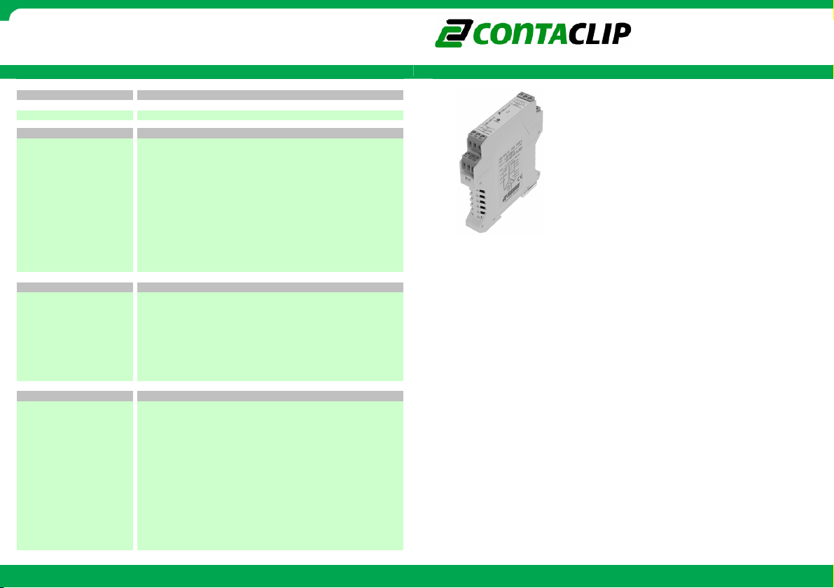
connection system
insulation stripping length
100 Ohm
10mV/20uA
< 10mV / 20uA
EN60751/DIN 43760
EMC Directive 2004/108/EC, according requirements of EN 55011 and EN 61326-1
CONTA-ELECTRONICS
Multi
Multi----function Multi
function Multi----channel converter
MultiMulti
function Multifunction Multi
channel converter
channel converterchannel converter
Electrical specifications
Electrical specifications
Electrical specificationsElectrical specifications
Order informat ion
Order informat ion
Order informat ionOrder informat ion
type
cat.no
Input dat a
Input dat a
Input dat aI nput data
4 Multifunctional analog/dig. Inputs
input resistance (U)
configuration resistor (PT/ NI1000)
accuracy (PT1000 / NI1000)
RTD current (PT1000 / NI1000)
digital input min puls width
digital input HI / LO status
Output data
Output data
Output dataOutput data
2 analog/dig. outputs
analog output
analog output load
digital output
digital output current
digital output voltage
General data
General data
General dataGeneral data
configuration information
power supply voltage
current consumption
conversion error
response time (analog / digital)
temperature coefficient
operating temperature range
CE marking
CMS-BS100 manual rev2.fl.doc
Resistor type: Plug-in(Rt) 18K2-0.1% (not included), Temp. range -20°C .. 140°C
0…10V DC or 0(4)..20mA, short-circu it and overvoltage (24Vac/dc) protected
<1% FSR, <0.5% when calibrated on requested range(U, I or RTD)
Low Voltage Directive (LVD) 2006/95/EC, accor ding requirements of EN 50178
Further information: www.conta-clip.com
input type is selected via jumpers
0..1V / 0..10V / 0(4)..20mA / RTD / 24VDC(14..30V)
output type is selected via jumpers
U: > 1kOhm I: < 500Ohm
Optocoupler transistor output
100mA continious collector current
CMS-BS100 manual
10ms / 60us + minima l pulse width
99 x 17,5 x 114,5mm
CMS-BS100
15963.2
40K2 Ohm
0,5°C
0.52mA
500us
>14VDC / <4VDC
jumper selectable
5..40VDC
24V DC ±20%
Approx. 25mA
< 0,02% /K
-20°C…50°C
0,2 - 2,5 mm²
screw clamp
7 mm
Manual
Manual
ManualManual
Cat. No.: 95120.1
Features:
• 4 Multifunctional analog/digital inputs
• 2 Multifunctional analog/digital outputs
• several conversion functions included
• especially suited for customer-specific
applications
• Input range and output range selectable via
DIP switches
Further information: www.conta-clip.com
The CMS-BS100 is a multi-functional signal converter with
multiple inputs and outputs. Analog voltage-, current-,
RTD- and digital signals can be converted to analog or
digital outputs. Several common conversion functions are
already included, e.g.
- analog inverter(s)
- 1 input to 2 separate outputs
- 2 inputs to 1 output (highest or lowest input)
- 2 inputs to 1 output (difference between inputs)
- RTD (Ni1000, PT1000) to analog output(s)
- Potentiometer(s) to analog output(s)
- up/down (2 digital inputs) to 1 analog output,
with selectable ramp from 5sec to 30min.
- if analog input1>2 then digital output1 on
if analog input3>4 then digital output2 on
- pulse stretcher(s)
Furthermore, this module is especially suited for customerspecific applications. Due to its number of inputs and
outputs it can be programmed to measure the inputs and
control the outputs in any way or function the customer
desires.
Even for very low volumes, special programming can be
very interesting for you!
CMS
CMS----BS100
BS100
CMSCMS
BS100BS100
Page 2
CONTA-ELECTRONICS
Multi
Multi----function Multi
function Multi----channel converter
MultiMulti
function Multifunction Multi
channel converter
channel converterchannel converter
Configuration
Configuration Connection diagram
ConfigurationConfiguration
Connecting the module
Connecting the module
Connecting the moduleConnecting the module
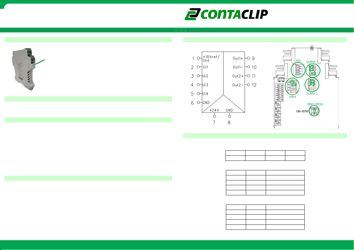
The pin configuration for I/O and power connection is shown on the top of the module.
The green Led on top indicates Power ON.
Input configuration
Input configuration
Input configurationInput configuration
The CMS-BS100 has 4 multifunctional inputs which can be configured for measuring voltage,
current, RTD and to detect digital signals. To configure the inputs a series of jumpers and/or
additional resistors(not included) have to be set according to the text on the PCB.
The inputs must be set as follows:
• Uin: jumper on U, resolution: jumper on 2.5V, no resistor placed
• Iin: jumper on I, resolution: jumper on 2.5V, no resistor placed
• RTD: no jumper on input, resolution: jumper on 1V, resistor 18K2 0.1% placed
• Digital in: jumper on U, resolution: jumper on 2.5V, no resistor placed
In the example drawing input1 is set to measure Voltage and input2 to measure current.
Output configuration
Output configuration
Output configurationOutput configuration
The CMS-BS100 has 2 multifunctional outputs which can be configured to output voltage,
current and digital signals. To configure the outputs a series of jumpers have to be set
according to the text on the PCB.
The outputs must be set as follows:
• Uout: jumper on U, 2 jumpers on ANA
• Iout: jumper on I, 2 jumpers on ANA
• Digital out: no jumper on U/I, 2 jumpers on DIG
In the configuration example output1 is set to output current and output2 to output digital
signals.
To open the module press the locking levers under the terminals with
a screwdriver.
The module is configured by setting the dip-switches and jumpers
according to this manual.
Further information: www.conta-clip.com
Connection diagram Configuration example
Connection diagramConnection diagram
Function
Function: splitter
: splitter
FunctionFunction
: splitter: splitter
Input1 is forwarded to both output1 and output2. This function is selected by setting the
dipswitches as shown below.
Select the input range:
Select the output range:
Cat. No.: 95120.1
DIP1
DIP1 DIP2
DIP1DIP1
off off off off
DIP5
DIP5 DIP6
DIP5DIP5
DIP7
DIP7 DIP8
DIP7DIP7
Further information: www.conta-clip.com
DIP2 DIP3
DIP2DIP2
DIP6 value
off off 0..10V / 0..20mA
off on 0..5V / 0..10mA
on off 2..10V / 4..20mA
on on 1..5V / 2..10mA
off off 0..10V / 0..20mA
off on 0..5V / 0..10mA
on off 2..10V / 4..20mA
on on 1..5V / 2..10mA
DIP6DIP6
DIP8 value
DIP8DIP8
Configuration example
Configuration exampleConfiguration example
DIP3 DIP4
DIP3DIP3
value
valuevalue
value
valuevalue
CMS
CMS----BS100
BS100
CMSCMS
BS100BS100
DIP4
DIP4DIP4
Page 3

CONTA-ELECTRONICS
Multi
Multi----function Multi
function Multi----channel converter
MultiMulti
function Multifunction Multi
channel converter
channel converterchannel converter
Function: inverter
Function: inverter
Function: inverterFunction: inverter
The value from input1 and/or input2 is forwarded inverted to resp. output1 and/or output2.
This function is selected by setting the dipswitches as shown below.
Select the input range:
DIP5
DIP5 DIP6
DIP5DIP5
Function: optocoupler out
Function: optocoupler out
Function: optocoupler outFunction: optocoupler out
The optocoupler out function behaves as shown in the switching diagram. Potentiometer P1
an P2 represent the threshold for input1, potentiometer P3 and P4 represent the threshold for
input2. Input1 switches output1 and input2 switches output2.
A:
A: output1/2 switches on when value P1/P3 is reached. The output1/2 switches off
A:A:
when value P1 - P2 / P3 – P4 is reached.
B:
B: output1/2 switches on when value P1/P3 is reached. The relays switches off when
B: B:
value P2/P4 is reached.
All potentiometers represent a percentage from the selected input value. Full left turn is 0%
and full right turn is 100%.
This function is selected by setting the dipswitches as shown below.
DIP1
DIP1 DIP2
DIP1DIP1
off off off on
input1
input1 input2
input1input1
DIP6 DIP7
off off off off 0..10V / 0..20mA
off on off on 0..5V / 0..10mA
on off on off 2..10V / 4..20mA
on on on on 1..5V / 2..10mA
DIP6DIP6
DIP1
DIP1 DIP2
DIP1DIP1
off off on off
DIP2 DIP3
DIP2DIP2
DIP7 DIP8
DIP7DIP7
DIP2 DIP3
DIP2DIP2
DIP3 DIP4
DIP3DIP3
input2
input2input2
DIP8 value
DIP8DIP8
DIP3 DIP4
DIP3DIP3
DIP4
DIP4DIP4
DIP4
DIP4DIP4
value
valuevalue
Select the input range:
Select the switching behaviour:
Function: RTD
Function: RTD
Function: RTDFunction: RTD
The RTD function forwards a temperature range from -20..140ºC to the selected output
range, input1 to output1 and input2 to output2. This function is selected by setting the
dipswitches as shown below.
Select the input RTD:
Select the output range:
Function: digital in to digital out
Function: digital in to digital out
Function: digital in to digital outFunction: digital in to digital out
Digital input1 and input2 will be forwarded to resp. output1 and output2.
This function is selected by setting the dipswitches as shown below.
Select the output type:
DIP5 input1
DIP5 input1 DIP6
DIP5 input1DIP5 input1
off off 0..10V / 0..20mA
on on 0..5V / 0..10mA
DIP7 output1
DIP7 output1 DIP8 output2
DIP7 output1DIP7 output1
off off A
on on B
DIP1
DIP1 DIP2
DIP1DIP1
DIP5 input1
DIP5 input1 DIP6 input2
DIP5 input1DIP5 input1
off off NI1000
on on PT1000
DIP7 output1
DIP7 output1 DIP8 output2
DIP7 output1DIP7 output1
off off 0..10V / 0..20mA
on on 2..10V / 4..20mA
DIP1
DIP1 DIP2
DIP1DIP1
output
output1111 output2
outputoutput
DIP5
DIP5 DIP6
DIP5DIP5
off off off off not inverted
off on off on inverted
DIP6 DIP7
DIP6DIP6
DIP6 input2
DIP6DIP6
DIP8 output2 value
DIP8 output2DIP8 output2
DIP2 DIP3
off off on on
on off off off
DIP2DIP2
DIP6 input2 RTD
DIP6 input2DIP6 input2
DIP8 output2 value
DIP8 output2DIP8 output2
DIP2 DIP3
DIP2DIP2
DIP7 DIP8
DIP7DIP7
CMS
CMS----BS100
CMSCMS
input2 value
input2 input2
DIP3 DIP4
DIP3DIP3
DIP3 DIP4
DIP3DIP3
output2
output2output2
DIP8 value
DIP8DIP8
value
valuevalue
value
valuevalue
DIP4
DIP4DIP4
RTD
RTDRTD
value
valuevalue
DIP4
DIP4DIP4
value
valuevalue
BS100
BS100BS100
Further information: www.conta-clip.com
Cat. No.: 95120.1
Further information: www.conta-clip.com
Page 4

CONTA-ELECTRONICS
Multi
Multi----function Multi
function Multi----channel converter
MultiMulti
function Multifunction Multi
channel converter
channel converterchannel converter
Function: absolute differential
Function: absolute differential
Function: absolute differentialFunction: absolute differential
The absolute differential between input 1 and 2 and/or input 3 and 4 will be forwarded to resp.
output1 and output2.
This function is selected by setting the dipswitches as shown below.
Select the input range:
DIP5
DIP5 DIP6
DIP5DIP5
Function: highest / lowest value
Function: highest / lowest value
Function: highest / lowest valueFunction: highest / lowest value
The highest / lowest value between input 1 and 2 and/or input 3 and 4 will be forwarded to
resp. output1 and output2.
This highest value is selected by setting the dipswitches as shown below.
DIP1
DIP1 DIP2
DIP1DIP1
off on off off
input1
input1 input2
input1input1
DIP6 DIP7
DIP6DIP6
off off off off 0..10V / 0..20mA
DDDDIP1
IP1 DIP2
IP1IP1
off on off on
Further information: www.conta-clip.com
DIP2 DIP3
DIP2DIP2
DIP7 DIP8
DIP7DIP7
DIP2 DIP3
DIP2DIP2
DIP3 DIP4
DIP3DIP3
input2
input2input2
DIP8 value
DIP8DIP8
DIP3 DIP4
DIP3DIP3
DIP4
DIP4DIP4
DIP4
DIP4DIP4
value
valuevalue
This lowest value is selected by setting the dipswitches as shown below.
Select the input range:
DIP5
DIP5 DIP6
DIP5DIP5
Function: analog to digital differential
Function: analog to digital differential
Function: analog to digital differentialFunction: analog to digital differential
Digital output1 switches when input1 > input2, output2 switches when input3 > input4.
The difference between the inputs must be >1%.
This function is selected by setting the dipswitches as shown below.
Select the input range:
DIP5
DIP5 DIP6
DIP5DIP5
Note: due to different resolutions this function cannot combine U/I in with RTD in. When
RTD is selected for input1/2, input3/4 must also be set as RTD.
Cat. No.: 95120.1
DIP1
DIP1 DIP2
DIP1DIP1
off on on off
input1
input1 input2
input1input1
DIP6 DIP7
off off off off 0..10V / 0..20mA
off off off off 0..10V / 0..20mA
off on off on NI1000
on off on off PT1000
DIP6DIP6
DIP1
DIP1 DIP2
DIP1DIP1
off on on on
input1
input1 input2
input1input1
DIP6 DIP7
DIP6DIP6
Further information: www.conta-clip.com
DIP2 DIP3
DIP2DIP2
DIP7 DIP8
DIP7DIP7
DIP2 DIP3
DIP2DIP2
DIP7 DIP8
DIP7DIP7
CMS
CMS----BS100
CMSCMS
DIP3 DIP4
DIP3DIP3
input2
input2input2
DIP8 value
DIP8DIP8
DIP3 DIP4
DIP3DIP3
input2
input2input2
DIP8 value
DIP8DIP8
DIP4
DIP4DIP4
DIP4
DIP4DIP4
value
valuevalue
value
valuevalue
BS100
BS100BS100
Page 5

CONTA-ELECTRONICS
Multi
Multi----function Multi
function Multi----channel converter
MultiMulti
function Multifunction Multi
channel converter
channel converterchannel converter
Function: pulse stretcher
Function: pulse stretcher
Function: pulse stretcherFunction: pulse stretcher
A pulse > 0.5ms on digital input1 and/or digital input2 stretches resp. digital output1 and/or
digital output2.
CMS
CMS----BS100
BS100
CMSCMS
BS100BS100
This function is selected by setting the dipswitches as shown below.
Select the output time:
DIP5
DIP5 DIP6
DIP5DIP5
Function: up / down digital input
Function: up / down digital input
Function: up / down digital inputFunction: up / down digital input
A pulse > 0.5ms on digital input1 or digital input3 increases resp. analog output1 and/or
analog output2 with a selected rise/fall time.
A pulse > 0.5ms on digital input2 or digital input4 decreases resp. analog output1 and/or
analog output2 with a selected rise/fall time.
The minimum and maximum value for the output values can be selected with P1 and P2 for
output1, P3 and P4 for output2.
This function is selected by setting the dipswitches as shown below.
DIP1
DIP1 DIP2
DIP1DIP1
on off off on
output1
output1 output2
output1output1
DIP6 DIP7
DIP6DIP6
off off off off 0.5 sec
off on off on 1.0 sec
on off on off 1.5 sec
on on on on 2.0 sec
DIP2 DIP3
DIP2DIP2
DIP7 DIP8
DIP7DIP7
DIP1
DIP1 DIP2
DIP1DIP1
on on
Further information: www.conta-clip.com
DIP3 DIP4
DIP3DIP3
output2
output2output2
DIP8 value
DIP8DIP8
DIP2
DIP2DIP2
DIP4
DIP4DIP4
value
valuevalue
Select the rise/fall time:
output1 P1 to P2
output1 P1 to P2 output2 P3 to P4
output1 P1 to P2output1 P1 to P2
DIP3
DIP3 DIP4
DIP3DIP3
off off off off off off 5sec
off off on off off on 10sec
off on off off on off 30sec
off on on off on on 1min
on off off on off off 3min
on off on on off on 5min
on on off on on off 10min
on on on on on on 30min
Cat. No.: 95120.1
DIP4 DIP5
DIP4DIP4
DIP5 DIP6
DIP5DIP5
Further information: www.conta-clip.com
output2 P3 to P4
output2 P3 to P4output2 P3 to P4
DIP6 DIP7
DIP6DIP6
DIP7 DIP8
DIP7DIP7
DIP8 value
DIP8DIP8
value
valuevalue
 Loading...