

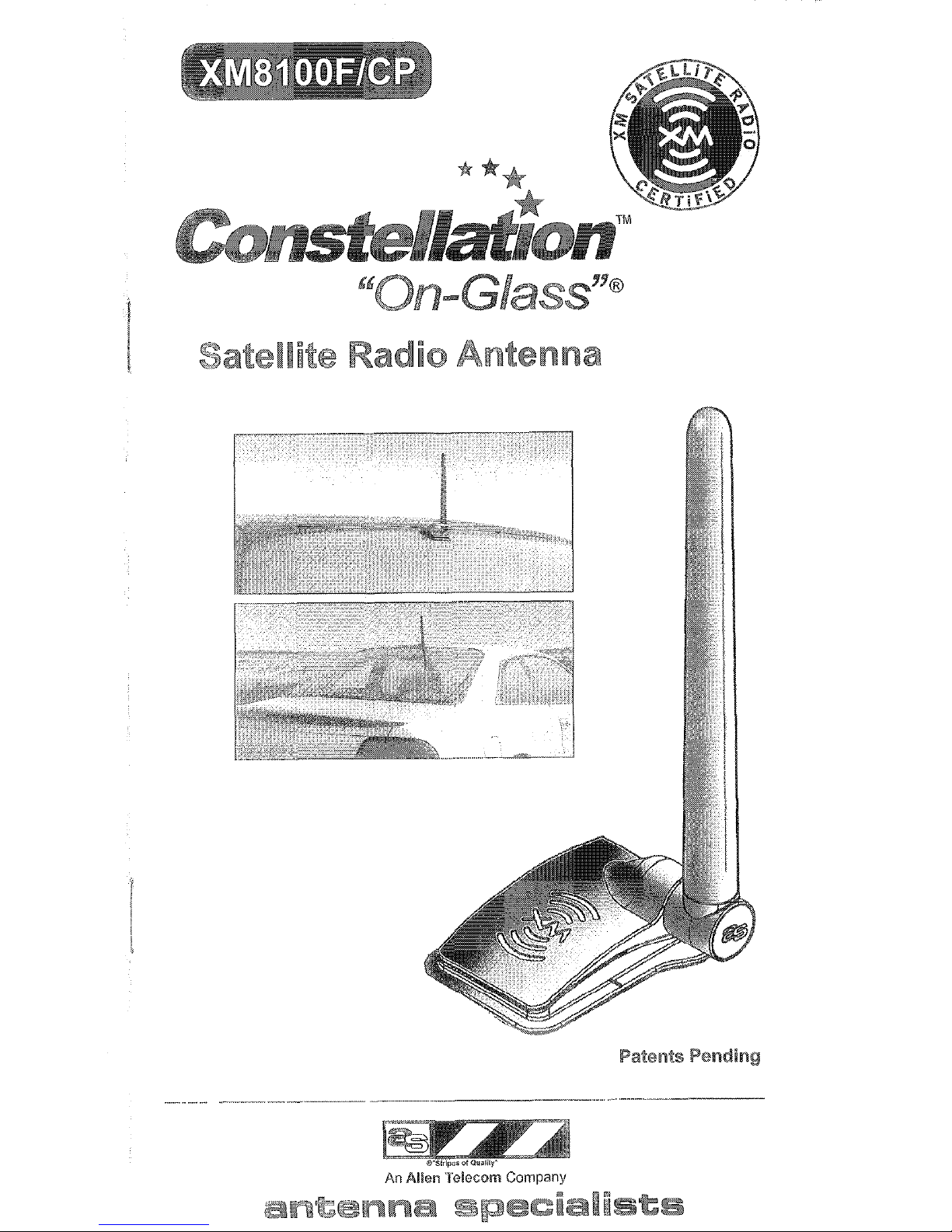
Constellation XM8100F/CP User Manual
..- . ..-.--.- -
_ _............... ._“.___
353
II
Radio
Patents Pending
An
Allen
Telecom Company
recorn~~~e~d~
any shortages call ~ntetina Specialist
97. (See Fig. I, page 4)
Integrity of the installation will be ~on~~rom~~ed if one or r
following are pr~~eflt at the planned ~t~~tailation location.
4. Rain XTM or other commercial water repellant.
2. After market window tinting material.
3. Glass waxes.
If present, remove material or select a different locatiol~ b
installing.
Do not install “On-Glass”@ antenna on %ront ~ind~hieid.
antenna must have an unobstructed view of the roofline,
clearance of roof racks, etc. (See Fig. 2, page 5)
Identify location of installation. Verify location using l‘emp
~u~at~~re Tool and instructions provided. Avoid locations
extremely curved glass.
Receiver location cannot be more than ‘I7 feet (via cable
antenna.
Check for cold weather install; the temperature must be a
ecord Serial No., Model No. and ~an~facturer’~ Code c
cover (see Fig. 22, pg. 14 for data location)
B must
Table
of
Contents
Pre-Installation Considerations
3
Vehicle
Mounting
locations
3
Parts
list
4
Installation Tips
5
Location
&Glass Preparation
6,
7
InstallationofExterior Base
8""11
InstallationofInteriorCoupler
12,13
Cable Routing
14
Trouble Shooting
15
Use &Care 15
***
Constellattonf
2
I
t: ~r~~~~~ionat in~~~lia~i~~l is highly r~~~rnrn~nd~d due ‘ro the
complexity of eledronic c~rnp~n~n~~ within the vehicle.
s Ilst. If any shor&ges call An&?nna Specialists ~us~~rn~r
7. (See Fig. 1, page 4)
ln~~gri~y of Ihe ins”rallation will be ~ompr~rni~~d if one or more of Ihe
fallowing are preset3 a’s the planned ins’rallatian location.
‘t . Rain XTM or other cammercial water repellan’r.
2. P&W market window tinting ma%erial.
3. Glass waxes.
If present, remove material or select 8 different location before
installing.
Do not install “Qn-Glass”@ antenna on front windshield.
~n~~t~~~~ mus8 have an unobsWded view of %he roofline, including
clearance of roof racks, etc. (See Fig. 2, page 5)
Identify location of installation. Verify location using Template, Glass
curvature Tool and instructions provided. Avoid locations with
extremely curved glass.
Receivc;r loca$ion canne’r be more than 17 feet (via cable routing) from
ar&nna,
Check for cold weather install; the ~~rn~~ra~ur~ must. be at least 60”
F.
Record Serial No., Model No. and ~anu~ac~ur~r’~ Code on back
cover (see Fig. 22, pg. 14 for data location)
Premlnstallation
Considerations
Iml30rtmllt: Professional installation is highly recommended due to the
complexity
of
electronic components within the vehicle.
Chock
parts
list. Ifany shortages call Antenna Specialists Customer
Service 800-321,·9977. (See Fig.
1,
page 4)
Integrity
of
the installation will be compromisedifoneormoreofthe
following are present at the planned installation location.
1.
Rain
XTM
or other commercial water repellant.
2.
After market window tinting material.
3.
Glass waxes.
If
present, remove material or select a different location before
installing.
Do not install "On-Glass"® antenna on front windshield.
Antenna must have an unobstructed view
of
the roofline, including
clearance of roof racks, etc. (See Fig.
2,
page
5)
Identify locationofinstallation. Verify location using Template, Glass
Curvature
Tool
and instructions provided. Avoid locations with
extremely curved glass.
Receiver location cannot be more than 17 feet (via cable routing) from
antenna,
Check for cold weather install; the temperature must be at least 60°
F.
Record Serial
No"
Model No, and Manufacturer's Code on back
cover (see Fig. 22, pg. 14 for data location)
CAUTION: Cable
must
NOT be
cutoraltered
ill
al"ly
mamier
as
reception
will
be adversely affected.
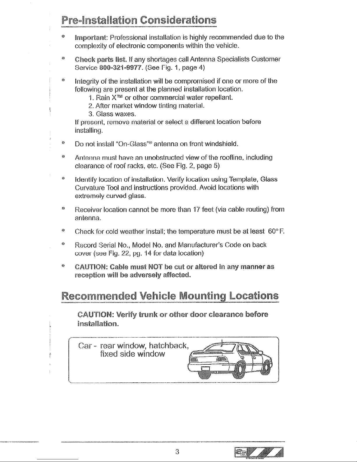
Recommended Vehicle
Mounting
Locations
CAUTION: Verify
trunkorother
door
clearance before
installation.
~
rear window, hatchback,
=~~;J
fixed side window
t:,
Green
Yell0 w
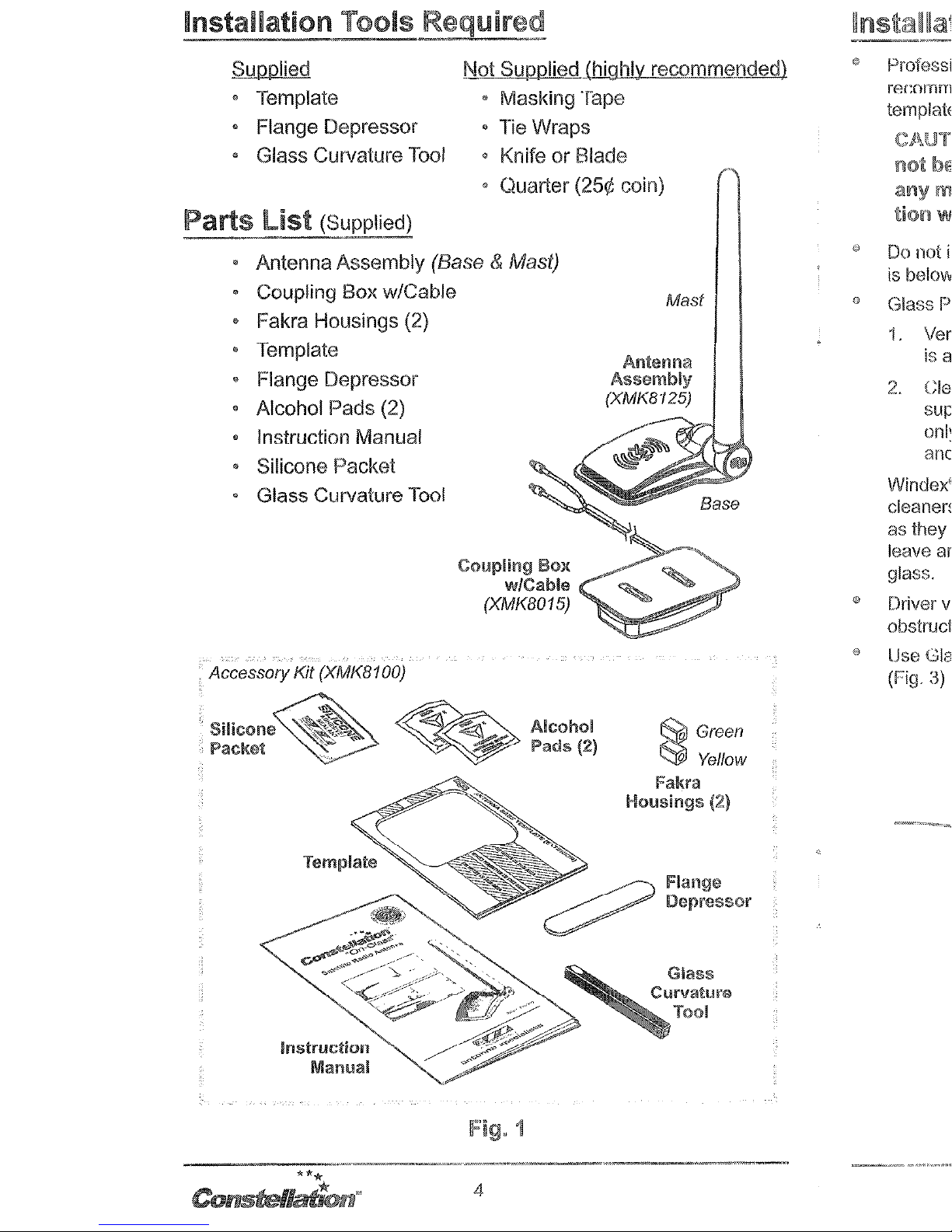
Not
Supplied (highly
recomm~osled)
• Masking Tape
• Tie Wraps
• KnifeorBlade
• ()uarter (25¢
COin)',
Installation Tools
R~nu
Supplied
o Template
• Flange Depressor
• Glass Curvature
Tool
Parts~
list
(Supplied)
• Antenna Assembly (Base
(fj,
Mast)
• Coupling Box w/Cable
• Fakra Housings (2)
• Template
• Flange Depressor
o Alcohol Pads (2)
• Instruction Manual
• Silicone Packet
• Glass Curvature Tool
AccessoryKit (XMK8100)
Mast
Antenna
Assembly
(XMK8125)
Silicone
PacKet
***
Constellatton"
4
Alcoho!
Pads (2)
E?eJ
Green
~
Ye/fow
Fakra
Housings
c
Lb32 Glass Curvature -?-a01
(Fig. 3)
@
Professional installation
(t<
Mount as high on glass as
recommended. Use supplied possible for optimal
perfor~
template and materials only!
manCEL
CAUTION: Cable mu.st
®
Do not install antenna over rear
riot be
cu.t
or
altered
in
brake light.
any manner, as
recepm
@
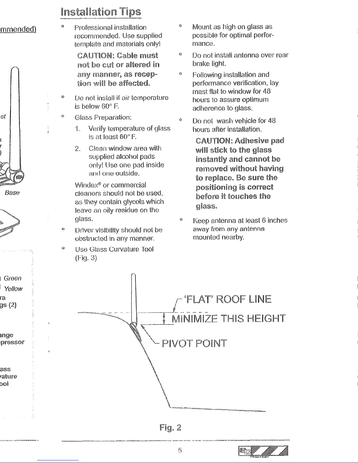
Following installation and
tio!1
will
be affected.
performance verification, lay
mast flat to window for 48
0
Do not install if air temperature
hours to assure optimum
is
below 60°
F.
adherence to glass.
Ii!
Glass Preparation:
0
Do not wash veh,icle for 48
'I. Verify temperature
of
glass
hours after installation.
is at least 60°
F.
CAUTION:
Adhesive
2. Clean window area with
will
sticktothe
gla$$
supplied alcohol pads
instantiy
and
cannot
be
only! Use one pad inside
removed
without
haVing
and olle outside.
to
Be
sure
the
Windex@orcommercial
positioningiscorrect
cleaners should not be used,
beforeittouches
the
as they contain glycols which
leave
an
oily residue
on
the
glass.
Keep antenna at least 6 inches
Driver visibility should not be
away from any antenna
obstructed in any manner.
mounted nearby.
Ii!
Use Glass Curvature Tool
(Fig. 3)
LINE
HEIGHT
2
5
1.
Identify location of in~t~llat~o~. Select a location that allows for
interior headliner clearance. Allow for rear window wiper ~le~r~t~~e
if present. Using the Glass puncture Tool, nie~~ure for low glass
curvature. (Fig. 3)
Glass preparation:
223)
2.b)
2.c)
Warm glass using a standard hairdryer,
: lk not use a
commercially available heat gun or other type of tool.
RESS AND FIRMLY
USE QUARTER TO
OLD DOWN ON 5OT.
ENSURE PROPER
GLASS CURVATURE.
IF COIN FITS
BETWEEN TOOLAND
GLASS, TRY ANOTHER
LOCATION.
3,
In order for adhesive to properly ~d~~ere to exterior surl
curvature of the glass must not be $euer~~ for best inst
Check far (;Llrv~t~re of glass using the tool provided.
oHold tool fl~~sh against glass surface, with finger a
tool dot (as shown in
* aping a quarter, slide it flush along the glass surfa
the o~po~i~~ end of the tool, as shown.
If the quarter fits beseech the tool (Fig. 3), the
~~rv~~~rl
severe for optim~i ir~~t~ll~ti~r~~ Select different
l~~~~ion
steps.
4,
~emo\/e ~aL]tior~ Label from antenna base and couple
tousling probes, as shown. (Fig. 4)
REMOVE CAUTION LABEL
/?
/’ \
COUPLER
Verify probes extend beyond ad~~~~ive pad surface, a$
(Fig. 5)
//- PROBES,
VERIFY ~I~I~HT~ND ADJUST AS
NECESSARY USING FLANGE
5EPRESSOF-2, BEING CAREFUL NOT
TO DAMAGE OR KINK PROBES.
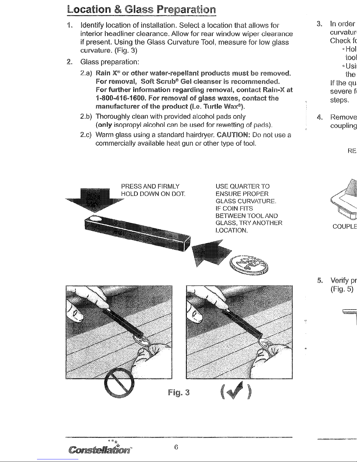
1. Identify location
of
installation. Select a location that allows for
interior headliner clearance. Allow for rear window wiper clearance
if
present. Using the Glass Curvature Tool, measure for low glass
curvature. (Fig. 3)
2. Glass preparation:
2.a)
Rain
X®orother
water·repel!~ult
products
ml.lst be
r1~moved.
for
removal, Soft Scrl.lb® Gel cleanser is recommended.
for
further
information regarding removal,
contact
Rain-X at
1.8(1)-416.1600.
For
removal
of
glass
waxes,
contact
tl'le
manufactl.lrer
of
the
prodl.lct (I.e. Turtie
Wax®).
2.b) Thoroughly clean with provided alcohol pads only
(only
isopropyl alcohol can be used for rewettingofpads).
2.c) Warm glass using a standard hairdryer. CAUTION:
Do
not use a
commercially available heat gun or other type
of
tool.
PRESS AND FIRMLY
HOLD DOWN ON DOT.
fig.
3
6
USE QUARTER TO
ENSURE PROPER
GLASS CURVATURE.
IF COIN FITS
BETWEEN TOOLAND
GLASS, TRY ANOTHER
LOCATION.
. In order for
adhesive
to pmperly adhere k2 exterior surf333, the
cu~lature of the glass must no% be severe, for best installatian.
Check for cuwa%ure of glass using the tool provided.
~Mald tool flush against glass sutiace, wifh finger applied or&
kml dot (as shown in Fig.3).
* Using a quarter, slide i% flush along ‘rhe glass sufiace toward
ahe ~~~o~i~~ end of the tool, as shown.
If the quarkr fits beneath the $ool (Fig. 3), the curvature is too
severe for optimal in§~~tl~~i~n. Select diffemm~ location I repetat
steps.
REMOVE CAUJION LABEL
ADJUSTED IN ORDER TO
MAKE CONTACT WI-l-ii GLASS
,//\
SURFACE (See
Step 5 below)
. Verify probes extend kayoed adhesive pad sutiace, as shown.
(Fig. 5)
VERIFY ~~IG~T~~R ADJUST AS
NECESSARY USING FkANGE
DEPRESSOR, BEING CAREFUL NOT
TO DAMAGE OR KINK PROBES.
3.
In
order for adhesive to properly adhere to exterior surface, the
curvature
of
the glass must not be severe, for best installation.
Check for curvature
of
glass using the tool provided.
o Hold tool flush against glass surface, with finger applied onto
tool dot (as shown in Fig.3).
•Using a quarter, slide it flush along the glass surface toward
the opposite end
of
the tool, as shown.
Ifthe qUalier fits beneath the tool (Fig. 3), the curvature is too
severe for optimal installation. Select different location - repeat
steps.
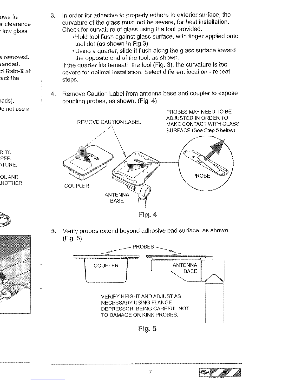
4. Remove Caution
label
from antenna base and coupler to expose
coupling probes, as shown. (Fig. 4)
PROBES MAY NEED TO BE
ADJUSTED
IN
ORDER TO
MAKE CONTACT WITH GLASS
SURFACE (See Step 5 below)
I
I
Fig. 4
5.
Verify probes extend beyond adllesive pad surface, as shown.
(Fig.
5)
VERIFY HEIGHTAND ADJUST AS
NECESSARY USING FLANGE
DEPRESSOR, BEING CAREFUL NOT
TO DAMAGE OR KINK PROBES.
5
7
 Loading...