

Page 1
TDMA CONTROL 602-702 Eng Nov.doc
1
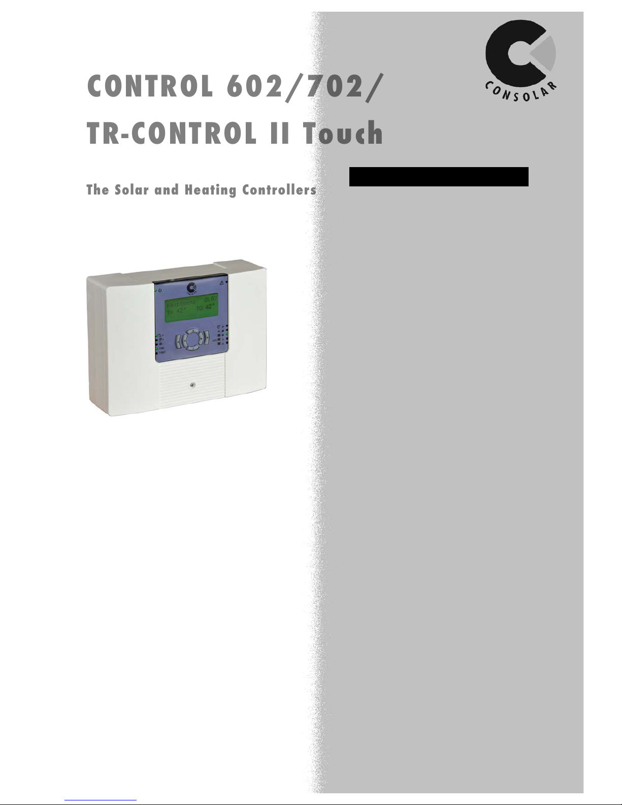
CONTROL 602/702/
CONTROL 602/702/
TR
TR--
CONTROL II Touch
CONTROL II Touch
The Solar and Heating Controllers
The Solar and Heating Controllers
Operating Instructions
Solar:
• Solar Control with Stratification Logic
• New: Operation of Solar Pump under partial shade conditions
• Capture the solar yield with or without a flow meter
• New: East / West with two pumps
• Cooling Function
• Control for two thermal stores
• Swimming pool function
Boiler control and integration:
• New: single-stage or modulating control of the boiler (power or
temperature)
• Solid fuel boiler control
• Return temperature raising or boiler buffering
Heating systems:
• Control of up to 3 heating circuits with the CONTROL 702
• New: screed drying function
Hot water system:
• New: Programmable timer for 3 hot water temperatures: set back /
normal / extra comfort
• Circulation control schedule
Additional Functions:
• Multi-functional Temperature differential Controller
• Multi-functional Temperature Switch
• New: Holiday mode allows disabling of auto-heating & dhw for a set
period of days
• New: service engineer’s telephone number can be stored and
displayed in the event of a fault occurring
• New: Data logger, Parameter storage and operating system update via
SD Card
• Optional: Remote control and room thermostat function through the
use of the TR-CONTROL 2 Touch
• Display texts in four languages
Note: The features available differ between both variants (see Function
Table).
The CONTROL 602 / 702 series are generalpurpose solar and heating controller with a range
of features for high energy-efficient operation of
the system.
For boiler and heating systems in old and new
buildings, the efficient operation is due to the large
range of functions available. The majority of
commercially available boilers, even modulating
boilers can be operated via the CONTROL 602 /
702.
The SD Card captures data, stores it and uploads
the setting in case of problems occurring. The data
can be transferred to other systems or remote
access to the plant can be achieved via a standard
LAN interface and web portal.
Page 2

TDMA CONTROL 602-702 Eng Nov.doc
2
1
GENERAL INFORMATION 3
1.1 Information on the Documentation 3
1.2 Storgae 3
1.3 Symbols 3
1.4 Limitation of Liability 4
1.5 Copyright Protection 4
1.6 Warranty Provision 4
1.7 Support and Customer Service 4
1.8 CE – Declaration of Conformity 4
2 SAFETY 5
2.1 Special Hazards 5
2.2 Conduct in Emergency Situations and Accidents 5
3 TECHNICAL DATA 6
3.1 Technical Data CONTROL 602 6
3.2 Technical Data CONTROL 702 7
3.3 Technical Data TR-CONTROL II Touch 7
4 OPERATION 8
4.1 Structure 8
4.2 Explanation of Symbols 8
4.3 Assisgnment of the Control Buttons 8
4.4 Menu Structure 9
4.5 Operation of the TR-CONTROL II Touch 10
5 FUNCTIONS AND SETTINGS 11
5.1 Display Values (Temperature and Calculated Values) 11
5.2 Variant Options 11
5.3 Functions Error! Bookmark not defined.11
5.4 Solar system Operation Function (Solar Input) 14
5.5 Yield Measurement (Calculated Input) 18
5.6 Hot Water Operation Function (Water Input) 20
5.7 Heating System Operation Functions (Heating Input) 24
5.8 Boiler Control Function (Boiler Input) 30
5.9 T-PRO / T-PRO 2 / T-PRO 3 35
5.10 Holiday Function 36
5.11 Service Menu 37
5.12 Firmware (Software) Updates via SD-Card 39
5.13 CONTROL 602: Sample Variant A 41
5.14 CONTROL 602: Sample Variant B 44
5.15 CONTROL 702: Sample 48
5.16 TR-CONTROL II Touch Special Functions 52
6 ASSEMBLY CONTROL 602 54
6.1 Mounting of the CONTROL 602 54
6.2 Electrical Connections CONTROL 602 55
7 ASSEMBLY CONTROL 702 59
7.1 Mounting of the CONTROL 702 59
7.2 Electrical Connections CONTROL 702 62
8 ASSEMBLY AND OPERATION OF THE TR-CONTROL II TOUCH 66
8.1 Wiring up the TR-CONTROL II Touch 66
8.2 Mounting the TR-CONTROL II Touch 66
8.3 Electrical Connections TR-CONTROL II Touch 67
8.4 Operation 68
9 FAULT AND FUNCTION CHECK 69
9.1 Solar Control without Additional Functions 69
9.2 Solar Control with Active Frost Protection 69
9.3 Solar Control with Two Thermal Stores 70
9.4 Solar Control with Heating Function 71
Page 3
TDMA CONTROL 602-702 Eng Nov.doc
3
1 General Information
In this technical documentation, the installation and operating instructions are the
‘Original Instructions’.
1.1 Information on the Documentation
This documentation provides information on installation and instructions for the use
and operation of the system. Conditions for safe operation, compliance with all
specified safety and handling instruction.
1.2 Storage
This document should be handed over to the owner of the system after successful
commissioning. It should remain with the owner and be made available for future
servicing and maintenance requirements of the system.
1.3 Symbols Used
-> WARNING NOTICES
DANGER!
Indicates an imminent hazardous situation, which leads to death or serious injury f not
avoided.
WARNING!
Indicates an imminent hazardous situation that can result in death or serious injury if
not avoided.
CAUTION!
Indicates an imminent hazardous situation that can lead to minor injuries, if not
avoided.
Attention!
Indicates an imminent hazardous situation that can lead to property damage if not
avoided.
-> TIPS AND ADVICE
NOTE!
Highlights useful tips and advice with recommendations for efficient and trouble-free
operation.
-> SPECIAL PRECAUTIONS
Risk of Electric Shock
Fall Risk – if necessary, wear a safety belt or wear appropriate protective clothing.
Page 4

TDMA CONTROL 602-702 Eng Nov.doc
4
1.4 Limitations of Liability
All information and instructions in this document have been compiled in accordance
with the applicable standards and regulations, plus our many years of experience.
The manufacturer assumes no liability for damages due to:
• Failure to follow the documentation
• Improper use
• Installation by non-trained personnel
• Unauthorised modification
• Use of unauthorised replacement parts
The actual scope of delivery can differ from the descriptions and illustrations given
here in case of special designs, additional ordering options or the latest technical
changes.
1.5 Copyright Protection
Copyright laws protect the content of information, text, illustrations and other
depictions. Any further use requires the approval of Consolar. Any unauthorised use
is forbidden and will lead to legal proceedings being implemented.
1.6 Warranty Provision
The warranty terms are in the separate document ‘Consolar warranty certificate’ and
in the price list.
1.7 Support and Customer Service
Technical information is available from the specialist companies we support.
Technical Support:
01452 772035
1.8 CE – Declaration of Conformity
We, Consolar Solare Energiesysteme GmbH, declare under sole responsibility that
the product CONTROL 602 and CONTROL 702 with the following standards:
2004/108/EG (EMC Directive)
DIN EN 61326-1; DIN EN 61326-2-2; DIN EN 55011; DIN EN 61000-3-2;
DIN EN 61000-3-3; DIN EN 61000-4-2; DIN EN 61000-4-3; DIN EN 61000-4-4;
DIN EN 61000-4-5; DIN EN 61000-4-6; DIN EN 61000-4-11
2006/95/EG (Low Voltage Directive)
DIN EN 61010-1
Page 5
TDMA CONTROL 602-702 Eng Nov.doc
5
2 Safety
Please read the following instructions for installation and commissioning carefully
before you start installing the equipment and putting into operation. This will prevent
damage to the plant, which can result from improper handling. All work must be
carried out in accordance with relevant local and VDE guidelines by authorised
personnel only.
2.1 Special Hazards
DANGER of Electric Stock!
In case of contact with live components there is immediate danger to life. Damage to
the insulation or components can be fatal.
Therefore:
• If damage has been caused to the insulation, turn off the power immediately
and arrange for repair.
• Work on electrical systems should only be undertaken by suitably qualified
electricians.
• Before doing any work on electrical systems, check that the system is isolated
and safe.
• Ensure the fuse is not bypassed or the system overridden. When replacing
fuses, ensure the correct amperage fuse is used.
• Keep all moisture away from live parts, as this can cause short circuits.
2.2 Conduct in Emergency Situations & Accidents
Preventive measures
• Always be prepared for any accidents or fires that may arise.
• Have first-aid equipment and fire extinguishers handy.
• Personnel should familiarise themselves with first aid equipment and rescue
facilities.
• All access routes should be kept clear for emergency vehicles.
Correct action in case of
emergency
• Switch off plant immediately.
• Initiate first aid if required.
• Remove persons from danger.
• Inform Site Manager.
• Raise the fire alarm and/or medical assistance.
• Make sure access routes are clear for emergency vehicles.
Page 6
TDMA CONTROL 602-702 Eng Nov.doc
6
3 Technical Data
3.1 Technical Data CONTROL 602
Base Unit:
Plastic housing 235 x 170 x 75 mm
Protection:
IP 20
Operating Voltage:
230 V ±10%, 50 Hz, AC
Power Consumption:
max. 10 W
Ambient Temperature
0°C...40°C
Outputs / Inputs
Switching Outputs
A1…A7: Semi-conductor Triac 230V, max. 2A, Fused with glass fuse 3
x15A slow blow, only suitable for the loads
Switch
A8: potential-free changeover relay, max. 240 V, max. 2A, not
protected
Analogue Outputs 1...2
a.) 0V ... 10V, minimum load resistance 1 kOhm
b.) PWM, max. 1 kHz, minimum load resistance 1 kOhm
Analogue Inputs ES
0V...10V, Load resistance 10 kOhm, resolution 10 Bit
supply voltage: 18V...24V, max. 100mA
Digital Inputs D1,D2
a.) Potential-free contacts
b.) Open Contact: low < 10V, high > 14V
Supply voltage: 18V...24V, max. 100mA
Ethernet interface
10/100 BASE-T
Temperature sensor inputs
10 x RTD Type Pt1000, Class B
Scale range: -40°C ... 350°C
Measuring range: -20°C ... 150°C
Accuracy in measuring range: +/- 1°C
Operation:
Menu driven
Service menu:
Each output can be switched manually.
Temp. in
°C
-10 0 10
20
30
40
50
60
70
80
90
100
110
R in Ohm
961,5
1000
1038,5
1077
1115,5
1154
1192,5
1231
1269,5
1308
1346,5
1385
1423,5
Note:
The details and advice in the Technical Documentation do not claim to be
comprehensive and are not a replacement for professional planning. Errors and
omissions accepted.
Page 7

TDMA CONTROL 602-702 Eng Nov.doc
7
3.2 Technical Data CONTROL 702
Base unit:
Plastic housing, ca. 235 x 170 x 130 mm
Protection:
IP 20
Operating Voltage:
230 V ±10%, 50 Hz, AC
Power consumption:
max. 10 W
Ambient temperature:
0°C...40°C
Output / Input:
Switching outputs:
A1…A17: Semi-conductor Triac 230V, max. 2A, fused with glass fuse 3
x 15A slow blow, only suitable for the loads
Switch:
A18…A19: potential free changeover relay, max. 240 V, max. 2A,
not protected
Analogue outputs 1...6
The Analogue outputs 3…6 are not used
a) 0V ... 10V, ± 5 %, minimum load resistance 1 kOhm
b) PWM, max. 1 kHz, minimum load resistance 1 kOhm
Analogue inputs ES
0V...10V, load resistance 10 kOhm, resolution 10 Bit
supply voltage: 18V...24V, max. 100mA
Digital inputs D1…D6
a) potential free contacts
b) Open Contact: low < 10V, high > 14V
supply voltage: 18V...24V, max. 100mA
Ethernet interface
10/100 BASE-T
Temperature sensor inputs
24 x resistance temperature sensors Type Pt1000, class B
Scale range: -40°C ... 350°C
Measuring range: -20°C ... 150°C
Accuracy in measuring range: +/- 1°C
Operation:
Menu driven
Service menu:
Each output can be switched manually.
Temp. in
°C
-10 0 10
20
30
40
50
60
70
80
90
100
110
R in Ohm
961,5
1000
1038,5
1077
1115,5
1154
1192,5
1231
1269,5
1308
1346,5
1385
1423,5
3.3 Technical Data TR-CONTROL II Touch
Base unit:
Plastic housing, ca. 132 x 90 x 21 mm
Protection:
IP 20
Power Input
Max. 2 W
Ambient temperature:
0°C...40°C
Room sensor accuracy
+/- 0.5 oC (with wall compensation)
Note:
The details and advice in the technical documentation do not claim to be
comprehensive and are not a replacement for professional planning. Errors and
omissions excepted
Page 8
TDMA CONTROL 602-702 Eng Nov.doc
8
4 Operation
4.1 Structure
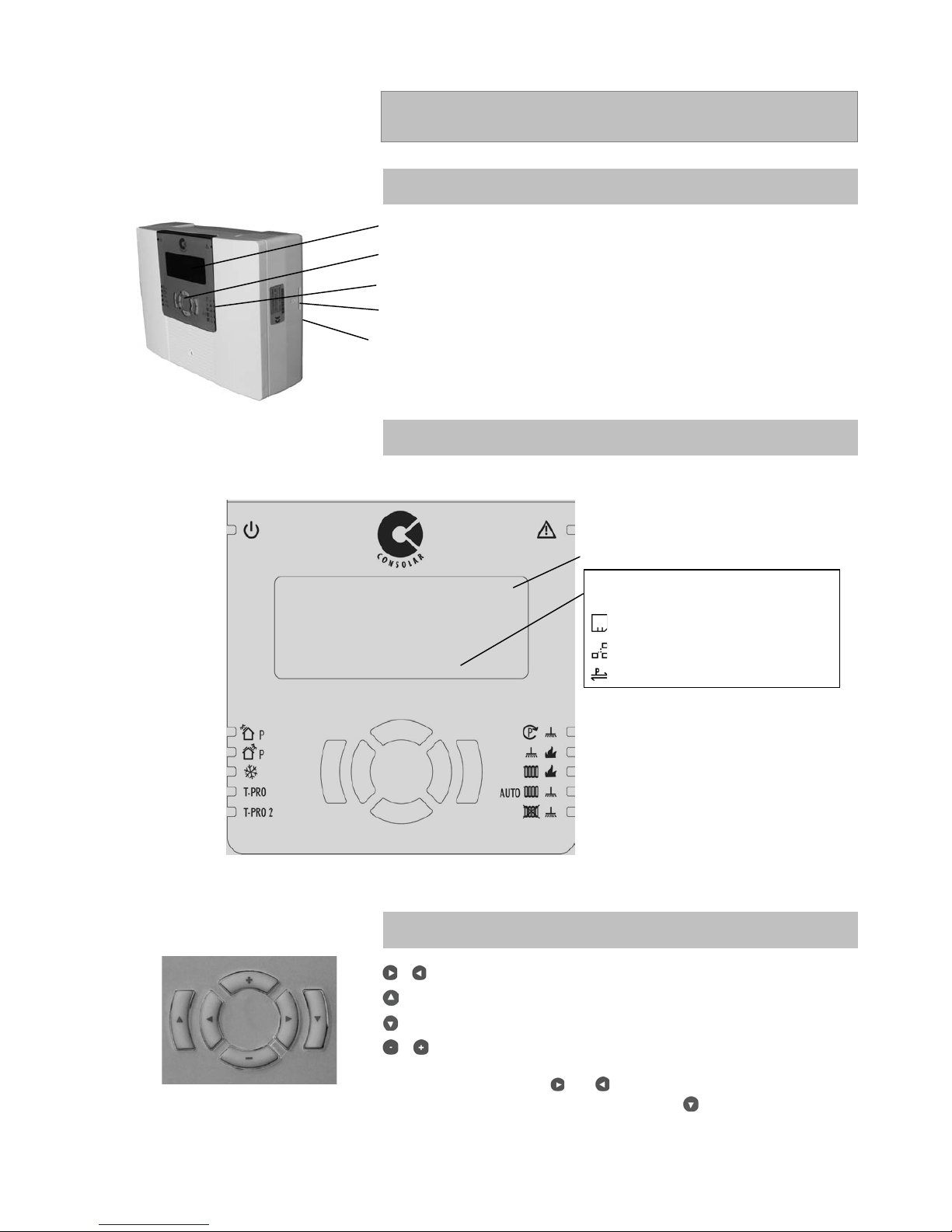
Display
Control Buttons
Status Indicators
Slot for SD-Card
Name plate with Serial Number
4.2 Explanation of Symbols
* LED Solar pump: Light On = Solar pump running; Light Flashing = Solar pump in intermittent mode (see 5.4.2)
4.3 Assignment of the Control Buttons
/ Forwards & Backwards within a Menu Option
Return to Previous Screen
Confirming Entry (Enter) or Change in Menu Offered
/ Increase/ Decrease/ Change of Parameters
Simultaneously pressing the and -> for Main MenuThe display values
flashes after it has been changed and by pressing will confirm the value
and store it.
Operating
Solar Pump *
East - West
T-PRO
T-PRO 2
Fault
∇ Submenu available (Press Enter Key)
Circulation Pump
Heating Requirement
Heating & Hot Water in Auto Mode
Hot Water in Auto Mode: Heating is Turned Off
Depending on the operational state the
following symbols may be displayed here:
SD Card is inserted
Network connection exists
Connection active to remote site
Circle – Professional menu / no circle – end
user menu
Hot Water Requirement
Page 9
TDMA CONTROL 602-702 Eng Nov.doc
9
4.4 Menu Structure
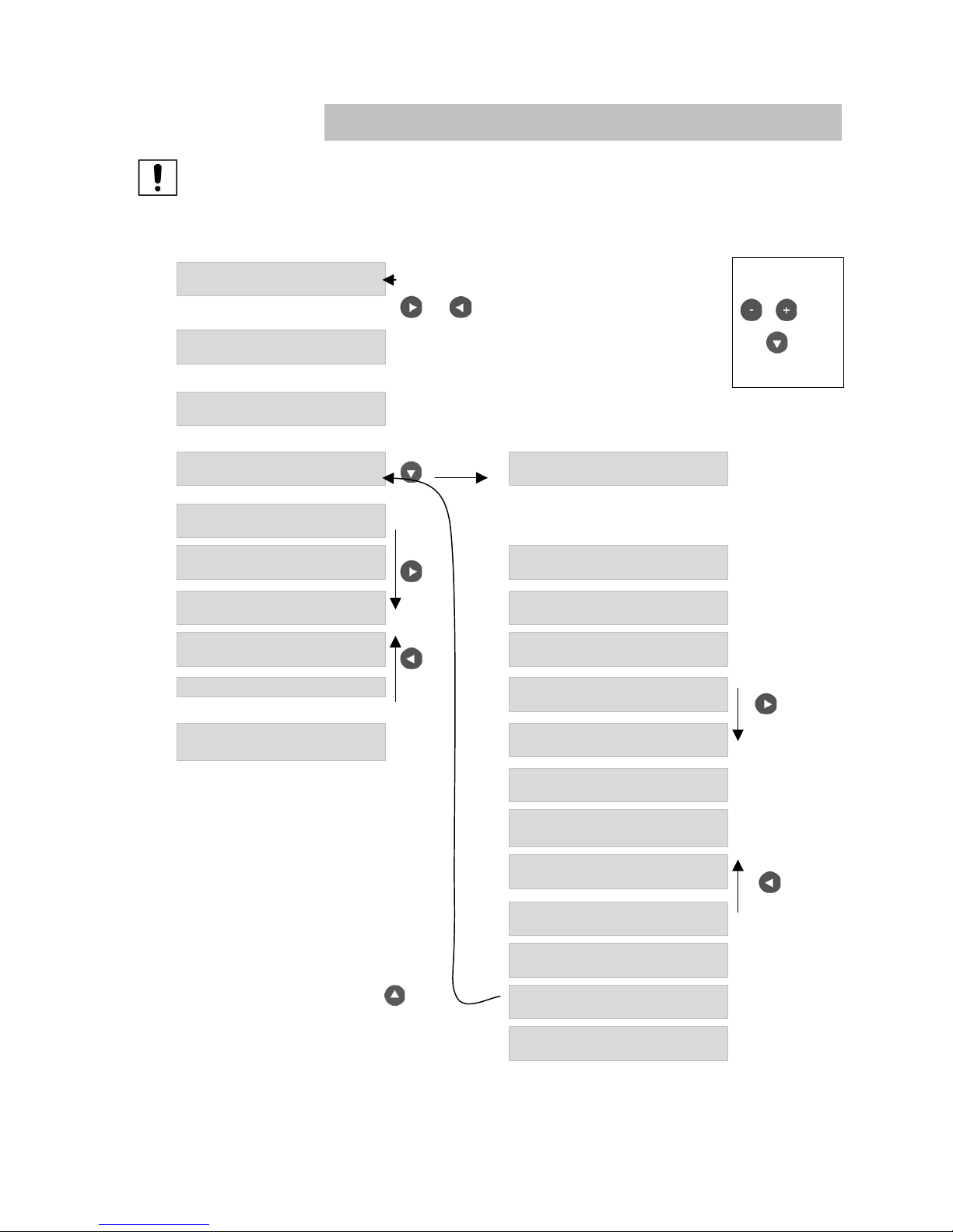
Note:
Only qualified personnel should do the input of the system parameters.
The chart below shows an example of the CONTROL 602, Version A menu structure.
Main menu
Sub menu
!"#$%!&$'%%%%%%%%%%%()*+,%
-.*%/0%1%%%%%%%%%%-2*%30%1%
Simultaneously
Press the
and
!"#$%!&$'%%%%%%%%%%()*+,%
-&45&6"7'6&8%
Setting Values:
/ and
with to
confirm.
!"#$%!&$'%%%%%%%%%%()*+,%
9":;%<":'&8%
*
!"#$%!&$'%%%%%%%%%%()*+,%
<"6#"$78%
Change to Sub
Menu
<"6#"$7%%%
%%%%%=%
*
!"#$%!&$'%%%%%%%%%%()*+,%
>&7%>?:"6%
*
!"#$%!&$'%%%%%%%%%%()*+,%
>&7%@?7%A"7&6%
Next Menu:
>76"7#B#;"7#?$%
C'$;7#?$*%%%%%%%%%%%%%%='7?%
*
!"#$%!&$'%%%%%%%%%%()*+,%
>&7%9":;%<":'&8%
=DD#7#?$":%C'$;7#?$%(%
E#&:D%
!"#$%!&$'%%%%%%%%%%()*+,%
>&7%@&"7#$F%
Previous Menu:
=DD#7#?$":%C'$;7#?$%)%
9??:#$F%
@?:#D"G8*%%%%%%%%%%%%%%%%%%%%%%%%%%%%%%%%%%%0%%%H"G%I8J%
=DD#7#?$":%C'$;7#?$%+%
@?7%A"7&6%9K"6F&%
Next Menu:
!"#$%!&$'%%%%%%%%%%()*+,%
>&6L#;&%
=DD#7#?$":%C'$;7#?$%,%
9#6;':"7#?$%
=DD#7#?$":%C'$;7#?$%3%
M?%C'$;7#?$%
=DD#7#?$":%C'$;7?$%/%
M?%C'$;7#?$%
>&:&;7%C'$;7#?$%(%
N?#:&6%O6&%@&"7%
Previous Menu:
>&:&;7%C'$;7#?$%)%
P"87QA&87%)%O'458%
>&:&;7%C'$;7#?$%+%
M?%C'$;7#?$%
Return to Previous Menu:
>&:&;7%C'$;7#?$%,%
M?%C'$;7#?$%
>?:"6%#$%4"R%
L#"*%E#&:D%>&$8?6%
Page 10
TDMA CONTROL 602-702 Eng Nov.doc
10
4.5 Operation of the TR-CONTROL II Touch
4.5.1 General Operations
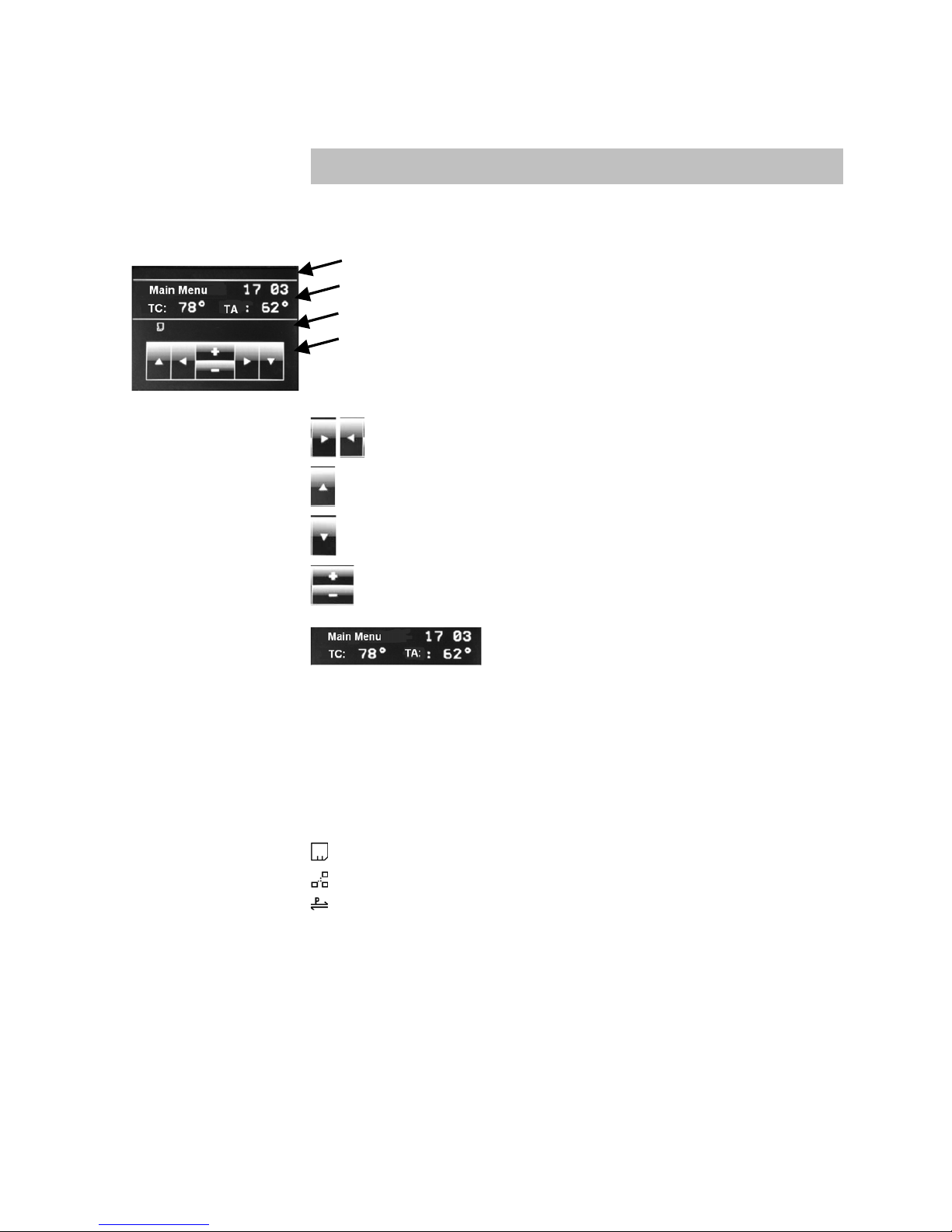
Status Bar (The area aove the display screen)
Display-Screen
Info Bar (The area between the display screen and keypad)
Buttons
Buttons:
Back & forth within a menu
Back one menu level
Confirmation of entry (Enter) or change in the menu offered
Increase/ decrease/ change the parameters
Touching this area returns you to the main menu
Status Bar:
The following information is displayed here:
Top Right: = in Professional Menu - No O = Customer Menu
Top Left: X (red cross) = Fault - No X = No Fault
Info Bar:
The display shows the symbols below showing the operating conditions:
∇ Submenu available (press Enter key)
After changing a value the figure flashes and an exclamation mark appears above the
enter button. On pressing the Enter button, the value is confirmed and saved. A green
tick appears above the enter button to show confirmation of the change.
Page 11

TDMA CONTROL 602-702 Eng Nov.doc
11
5 Functions and Settings
5.1 User Levels
The controller has two user levels:
1. End User Level: – Delivery of the controller is in this menu level. The setting of all
necessary everyday items (eg. Hot water target temp, timers, room temperature, etc)
occurs in this level.
2. Professional Level: - To enable this menu the code 3003 must be inputed (Service
menu, Authorised – Service Menu section 5.11). The setting of all menu items (eg. Plant
variant, circuit paramenters, boiler parameters, etc.) occurs in this menu level. 30
minutes after the last entry, the controller automatically switches to the End User level.
5.2 Display values (Temperature and calc. values)
!"#$%!&$'%%%%%%%%%%%%%%%%()*+,%
-&45&6"7'6&%L":'&8%
Shows all measured temperatures, such as collector and store temperatures including
store top min/max temperatures.
!"#$%!&$'%%%%%%%%%%%%%%%%()*+,%
9":;%L":'&8%
Shows the various calc values, such as power, performance, and operation hours.
5.3 System Variants and Functions
!"#$%!&$'%%%%%%%%%%%%%%%%()*+,%
<"6#"$78%
With the CONTROL 602 the selection of the appropriate system variant must be chosen.
The CONTROL 602 is factory set to Variant A.
The CONTROL 702 only has one variant.
The menu system variants can only be set in the Professional menu (see Section 5.1)
%<"6#"$7%
=%S%N%
The variant required must be choen before any other setting on the CONTROL 602 can
be set. See table on page 12 for the functions available for each variant.
Basic function (Solar control): is always active; permantly set.
Additional function (e.g. radiation measurement): optional activatable. The
corresponding temperatures or settings only appear on the display when the feature is
activated.
Select function: Functions can be selected and activated between several different
functions.
=DD#7#?$":%C'$;7#?$*%
%
The particular function can be activated. If it is not required, it has ‘no effect’ and can
be set so that no sensor fault is reported. Refer to controller for connection details (See
section 5.13, 5.14 and 5.15)
>&:&;7%C'$;7#?$*%
%
With each ‘Select function’ only one function can be selected, the others will not be
active. See Variant A & B function list chart (section 5.13, 5.14 und 5.15).
Page 12
TDMA CONTROL 602-702 Eng Nov.doc
12
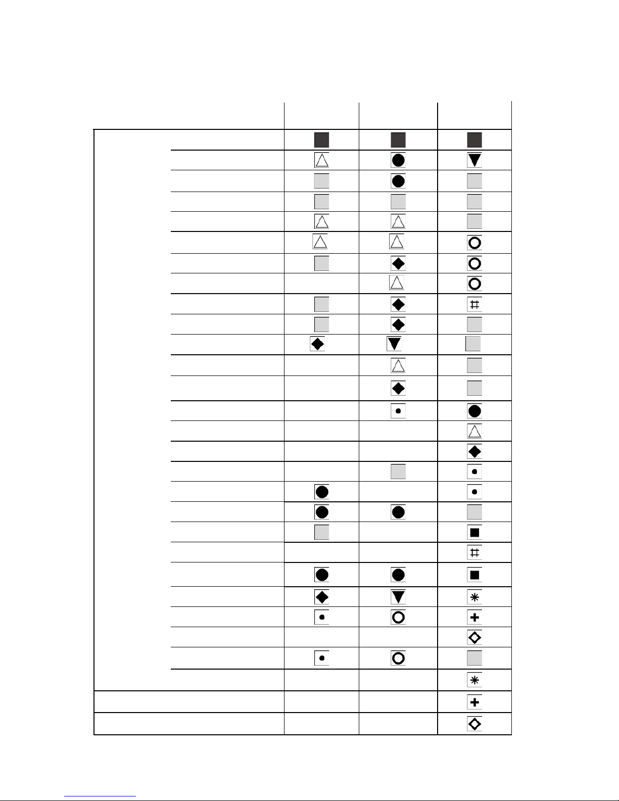
5.3.1 Function Overview CONTROL 602 / 702
CONTROL 602
Variant A
CONTROL 602
Variant B
CONTROL 702
Solar
Solar pump with or without top
loading (Stratification function*9)
East-West with 2 Pumps*2
Yield measurement
Radiation measurement
Active frost protection
Two stores (priority, equal
priority) swimming pool*2
*1
*1
Cooling
Cooling with heating circuit
*3
Hot Water
DHW heating with separate
output
Circulation
Circulation and bath button
*7
*8
*6
Boiler
Boiler control for hot water and
heating
Heating
Pump control for boiler and store
Heating Circuits
Heating mixing valve Circuit 1
Heating mixing valve Circuit 2
Heating mixing valve Circuit 3
Buffer logic
Return temperature raising
T-Control
T-PRO
T-PRO 2
T-PRO 3
Solid fuel boiler
Solid fuel boiler with temperature
differential control
Quantity of heat
detection
Heat meter 1
Heat meter 2
Heat meter 3
Flow meter for measuring solar
output *4
Thermostat (TR-Touch) Htg circ 1
Thermostat (TR-Touch) Htg circ 2
Thermostat (TR-Touch) Htg circ 3
Page 13
TDMA CONTROL 602-702 Eng Nov.doc
13
*1 Only when cooling is possible, *2 East/West with 2 Pumps and Swimming pool cnnot be activated together, *3 Only heating circuit is activated, *4
Only activated if heating circuit flow meter is available, *5 Not available for East/West with 2 Pumpsh, *6 Only available if the circulation is activated,
*7 Only available when the circulation function and hot water function are activated by a remote control, *8 Only possible when circulation function
and boiler control are enabled
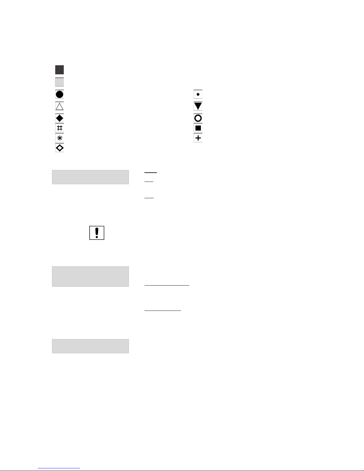
= Basic function: always active
= Additional function: can be activated
= Select function 1 (one function can be activated) = Select function 4 (one function can be activated)
= Select function 2 (one function can be activated) = Select function 5 (one function can be activated)
= Select function 3 (one function can be activated) = Select function 6 (one function can be activated)
= Select function 7 (one function can be activated) = Select function 8 (one function can be activated)
= Select function 9 (one function can be activated) = Select function 10 (one function can be activated)
= Select function 11 (one function can be activated)
>76"7#B#;"7#?$%%
C'$;7#?$*%%='7?%S%2$%S%2BB%
Auto: Stratification function with automatic switching to solar winter operation.
On: Stratification function without automatic switching to solar winter
operation.
Off: Simple differential temperature control, e.g. for store without stratified
solar load.
For explanation of stratification function, see section 5.4.2.
Note: Stratification function ‘AUTO’ is possible in Variant A only if the heating
return temperature raising is activated.
Stratification function cannot be activated in ‘East-West with 2 pumps’
(automaticall set to off)!
>?:"6%4"R#4'4%L#"*%%
E#&:D%!&"8'6&4&$7S9?::&;7?6%
>&$8?6%%
Yield Measurement: to enable, select ‘Yield Sensor’ in the menu and then
activate.
Via collector sensor: the maximum allowable collector fluid temperature
(110...115 °C) that can enter the solar heat exchanger is calculated from the
store bottom temperature.
Via yield sensor: The maximum temperature that may occur in the solar heat
exchanger is measured at the yield sensor (heat exchanger inlet). The solar
pump will shut down when the temperature exceeds 100 °C at the yield sensor
or 140 °C at the collector sensor.
H@A%N";TQ'5%K&"7#$F%L#"%%%
9?$76?:%%%%%%%%%%%E&8%S%M?%
%
Hot water back-up heating should be controlled by using the CONTROL 602 /
702 ‘Return Temperature Raising’ function. The back-up heating option should
be set to ‘Yes’. During the heating of the hot water standby component the
return temperature raising (3-way diverter valve) is interrupted, to prevent a
hydraulic short-circuit. The interruption of Return Temperature Raising also
occurs during the summer operation.
Page 14

TDMA CONTROL 602-702 Eng Nov.doc
14
5.4 Functions to Operate the Solar System (Solar Input)
!"#$%!&$'%%%%%%%%%%%()*+,%
>&7%>?:"6%
%
The microprocessor-controlled controller CONTROL 602 and CONTROL 702
are designed for optimum functionality and reliability of the Consolar solar
systems. Even for solar systems with other stores, these controllers can be
used. The controls allows for intelligent use of differing insolation and weather
conditions by automatically switching between three operating levels
depending on the solar loading..
5.4.1 Solar Pump Operation
9?::&;7?6%%%%%%%%%%E&8S%M?%
-'U&%C'$;7#?$%
This function allows the solar system to start, for example, with a temporarily
shaded collector. During this start-up period, the solar pump is switched
cyclically on and off for an adjustable duration.
%-?%>'U4&$'V%
If above was ‘Yes’ then you get the option by pressing the down arrow to go
to a submenu, where the following functions can be set or adjusted.
>7"67*%%%%%%%%%%%0W*00%K6%
-'U&%C'$;7#?$%
P$D*%%%%%%%%%%%%%0X*00%K6%
-'U&%C'$;7#?$%
>7?5%-#4&%
)%Y%30%!#$%
Z'$%-#4&%
[%Y%)0%>&;%
5.4.2 Operation of the Solar pump
Top Loading (Stratification Function): In good weather conditions, the full flow
of solar-fluid is only circulated without interruption once the collector reaches a
set minimum temperature (top loading temperature). The top loading
temperature is calculated automatically by the CONTROL 602 / 702 (DHW set
temperature + 5 K). The hysteresis is set at the factory with 2 K. The hot water
is then stratified loaded at the top of the Consolae store at a temperature 2..5
K lower.
Intermittent Operation: If there is not enough solar irradiation to heat the
collector on top loading, the controller switches on to intermittent operation.
That is, the CONTROL 602/702 waits a certain time, while the collector heats
up. This state is indicated by a flashing LED ‘Solar Pump’. After this fixed
period, it switches on the solar pump, unless during this period the solar
irradiation has increased and has reached the top loading setting and has
already started the solar pump. The run-time of the solar pump during
intermittent operation should be the length of time it takes to circulate the fluid
once through the system. In the Consolar store this lower temperature water is
automatically directed to the middle or lower storage areas. With intermittent
operation, usable temperature difference control. In summer, this avoids restarting the boiler.
Page 15

TDMA CONTROL 602-702 Eng Nov.doc
15
Preheating: In winter and during the transitional periods (ie., spring and
autumn) when the solar energy is not sufficient for top loading, the controller
will go into preheat mode. The heated water is then used to heat the store’s
buffer area.
9K"$F&%7?%!?D&%
A#$7&6*%%%%%%%%%%0\\\30%19%
%
Here the temperature can be set when the changeover takes place in the solar
system for winter operation. The solar pump will operate on a pure
temperature difference control. Switching over to winter operation is by either
the heating return sensor or the heating flow sensor dependenrt upon which
variant of the CONTROL 602 is selected. This is only possible if the
Stratification function is set to AUTO.
CONTROL 602
Control Setting
Sensor
Variant A
• Return temperature raising
• Heating return temperature
sensor
Variant B
• Heating control
• Flow sensor
H#BB&6&$;&%>?:"6*%
%%%%%%%%%%%%%%%%%%)\\\()%.%
%
The temperature difference between the collector sensor and the store
temperature is set here. If the collector sensor is higher than the bottom store
sensor by the amount set, then solar charging will take place. For small pipe
diameters and good thermal insulation, a small value can be set. For longer
pipelines, large diameter pipes, poor insulation or poor sensor configuration,
the temperature difference must be greater.
Example:
A 15 mm diameter pipe, 20 m long, pump with low power consumption and
good thermal pipe insulation, the value of 6 K can be set. In setting 6 K, the
solar pump will turn on when the temperature is ar least 6 K above the
temperature of the bottom store sensor. If the temperature difference between
collector and the bottom stoer temperature falls below 4 K (hysteresis of 2 K,
set at the factory), the solar pump shuts off
Solar pump: Allocation input - Function - Output
Input
Function
Collector sensor
(Supplied)
Top Loading (Stratified loading
function)
Solar Differential
Maximum Solar input
Store sensor bottom
(Supplied)
Solar Differential
Flow/Return flow sensors
(Art. Nr. RE 046)
Switch to Winter
Output: Solar pump
Page 16
TDMA CONTROL 602-702 Eng Nov.doc
16
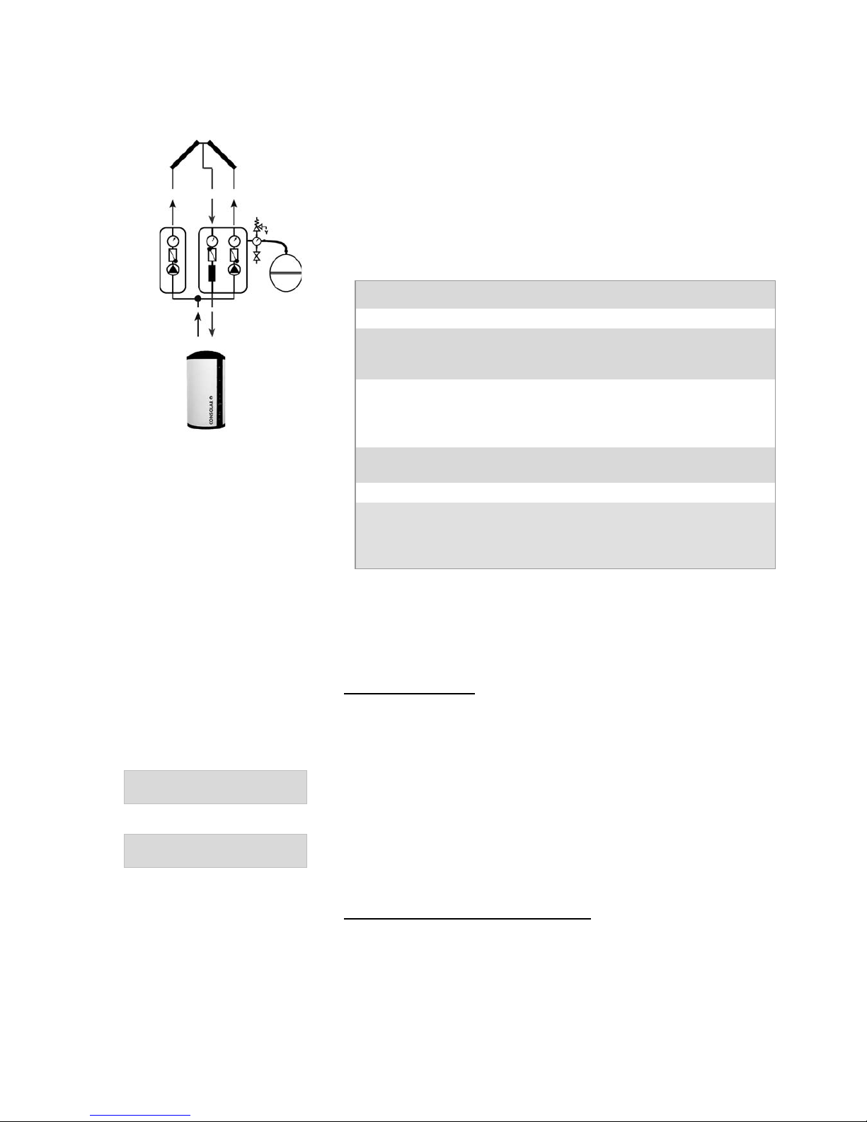
5.4.3 East-West-Control with two pumps
The ‘East-West with two pumps’ is for systems with two collector panals (fields),
which have different orientation. For example, one facing East and another
facing West. This function controls two separate solar pumps. Here, the
sensor F2 (store bottom sensor) is used to control both solar pumps, as a
reference sensor. If this function is activated, it automatically changes the
‘stratification functon’ to Off. When the solar yield function has been selected,
the controller starts to count when either of the two pumps run..
East-West with two Pumps: allocation input - Function - output
Input
Function
Collector sensor Field 1 (F1)
Activation conditions for solar
pump control 1 (Temperature
difference)
Collector sensor Field 2
CONTROL 602 Variant A (F8)
CONTROL 602 Variant B (F9)
CONTROL 702 (F11)
Activation conditions for solar
pump control 2 (Temperature
difference)
Store top sensor (F3)
Max. Permissible store
temperature (90°C)
Store bottom sensor (F2)
Differential Solar
Output:
Solar pump Field 1 (output A1)
Solar pump Field 2 (CONTROL 602 Output A3 in Variant A and Ouput A4 in
Variant B; CONTROL 702 Output A2)
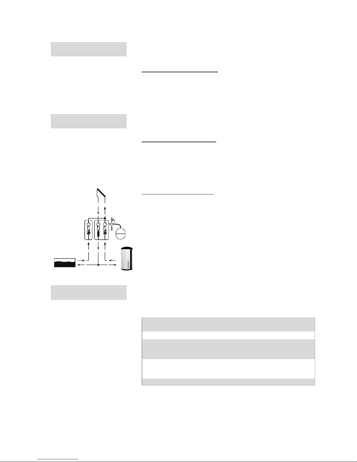
5.4.4 Cooling, Swimming Pool and two store control
This function is to prevent overheating of the collector or put heat to a second
store (or pool). The solar pump will continue during the cooling of the store as
long as the maximum collector or store temperature is not exceeded.
Select Function Cooling:
If the ‘store top sensor’ has reached the set ‘cooling temperature’, the output
‘cooling’ state is operated. This output can drive for example; a charging
pump to cool the store or redirect the heat to another store.
9??:#$F%-&45&6"7'6&*%
%%%%%%%%%%%%%%%%+0\\\X0%19%
Here the desired cooling temperature can be set.
@G87&6&8#8*%%
%%%%%%%%%%%%%%%%%%)\\\(0%.%
The hysteresis of cooling control can be set.
For example, with a cooling temperature of 85 °C and a Hysteresis of 5 K, the
output is activated at 85 °C and deactivated at 80 °C.
Seclect Function - Cooling via Heating Circuit:
When the store temperature is above a set value, the store can be cooled by
using heating circuit 1. The mixing valve and pump of heating circuit 1 is
operational.
The cooling temperature and hysteresis settings are described below.
Page 17
TDMA CONTROL 602-702 Eng Nov.doc
17
C:?]%-&45%@9%*%
9":;*%%%%%%%%%%%+0\\\X0%19%
The desired heating circuit flow set temperature in cooling mode is set here.
%
Select Function Two Store Priority: If the ‘store top sensor’ has reached the set
‘cooling temperature’, the output is switched to two store mode, for example,
to move a three-port valve to redirect the heat flow to another store.
Simultaneously, the store bottom sensor will switch to store bottom sensor 2.
The hysteresis setting is described in select function Cooling.
>]#7;K#$F%-&45&6"7'6&\*%
%%%%%%%%%%%%%%%+0\\\X0%19%
%
The desired switching temperature for the function ‘Two store priority’ and
‘Swimming pool’ are set here.
Select Function Two Store Equal: When the second thermal store bottom
sensor temperature is lower than that of the first, the ‘Two store’ function is
activated, This activates a tree-port valve so that the heat flow is diverted to
another thermal store, and simultaneously switches from the first to second
lower thermal store sensor. The hysteresis of 2 K is set in the factory.
Select Function Swimming Pool: When the store top sensor has reached the set
temperature the heat is switched to the pool heat exchanger. On contact
closure, the solar pump is switche doff and the pool pump is turned on, to
direct the heat flow into the pool heat exchanger. Simultaneously the store
bottom sensor switches to the second store bottom sensor.
The changeover temperature and hysteresis settings are described under two
Store Priority Select Function.
>]#44#$F%5??:%!"R*%
%%%%%%%%%%%%%%%%0\\\[0%19%
Here the swimming pool maximum temperature is set via the ‘second store
bottom sensor’.
Cooling, Two Store control and Swimming pool: allocation
Input - Function – output
Input
Function
Store Sensor Top
(Supplied)
Store max, Cooling, Two Store,
Swimming Pool
Store Sensor Bottom 2
(Art. Nr. RE 046)
Two Store, Swimming Pool
Output: Cooling, Two Store or Swimming Pool
Page 18
TDMA CONTROL 602-702 Eng Nov.doc
18
>7?6&%!"R*%
%%%%%%%%%%%%%%%%[0\\\X0%19%
If the store top sensor reaches above the set temperature, the solar pump is
switched off.
Note:
In some cases (such as a holiday in order to protect the system conponents) it
may be advisable to lower the maximum storage temperature to less than 90
°C. The cooling temperature should also be set below the maximum store
temperature, so that the collector does not stagnate.
5.4.5 Frost protection of solar circuit
2L&66'$%-#4&6*%
%%%%%%%%%%%%%%%%0\\\)0%4#$%
When the ‘Frost Protection’ option has been chosen, the sytstem for frost
protection is implemented. When the frost protection sensor falls below 5 °C
the solar pump is activated and when the teperature rises to 9 °C the pump
switches off. The frost protection circuit operates with vacuum tube collectors
and those that have water in the solar circuit. An overrun frost protection timer
(adjustable) allows the pump to run for a short period after the temperature
rises above the upper limit. Consolar does not recommend solar fluid that is
only water, as it may become frozen under adverse weather conditions and
cause the solar pump to fail.
!"#$%!&$'%%%%%%%%%%%()*+,%
9":;%<":'&8%
=$7#B6&&^&%-G5&%
%%%%%%%%O6?5G:&$%S%P7KG:&$%
C6?87%O6?7&;7#?$%O&6;&$7"F&%%%%%%0%_%
W0`%
5.5 Yield Measurement (Calc Values)
The solar yield is determined from the temperature differential between the
yield sensors on the heat exchanger inlet & outlet and the flow rate. The flow
rate can also be entered as a constant value, if no flow meter is installed.
However, the yield measurment can be fraught with msclculations and can be
up to 50% out, because the viscosity of the heat transfer fluid is highlt
temperature dependent.
Through these two settings, the parameters for the density and heat capacity of
the heat transfer medium can be determined. These parameters depend on
the temperature, mixing ratio of water/antifreeze and what type of antifreeze
used, from a propylene gycol mix: such as Tyforcor L; Tyfocor LS; Antifrogen
L; P-NF Liquid Reinsol; Ethylene Glycol; Tyforcor; Antifrogen N.
Obtainable from Consolar if Tyfocor LS (Item No. KR 130/135) whose
percentage of the antifreeze is set to 40%.
If a flow meter is installed for the CONTROL 602 Variant A choose ‘Select
Function 4’ or for Variant B choose ‘Select Function 6’ “Heat Meter”. For the
CONTROL 702 this is a basic function and does not have to be separately set.
C:?]4&7&6%H"7"%
0a00(\\\(%b#76&%S%5':8&%
If a flow meter is connected, the pusle rate of each metering unit can be
entered to allow for the automatic calculation of volume flow. Available from
Consolar is a flow meter (No. RE096) which is set at the controller with 0.026
l/pulse.
>?:"6%C:'#D%C:?]%%
0a(\\\+0%:S%4#$%
If a flow meter is connected, the flow rate must be set to 0 l/min. If no flow
meter is connected, the flow rate must be determined by using q Taco setter
and the vlue entered.
Note:
In ‘East-West with 2 Pumps’ if you enter the flow of one collector array, the
controller will assume that both arrays are the same!
Page 19

TDMA CONTROL 602-702 Eng Nov.doc
19
%
Yield Measurement: Allocation Input-Function-Output
Input
Function
Yield Sensor Flow (Solar Hot)
(Art. Nr. RE 046)
Temperature differential for Yield
calculation
Yield Sensor Return (Solar Cold)
(Art. Nr. RE 046)
Temperature differential for Yieldn
calculation
Flow Meter (Art. Nr. RE 096)
Flow measurement
No Output
5.5.1 Radiation Measurment (Input Data)
Z"D#"7#?$%>&$8?6*%
%%%%%%%%%%(00\\\([00%AS<4
)%
Here the solar radiation is measured. This requires a radiation sensor to be
connected.
In this menu option, the proportionality factor between the measured volatage
and the solar radiation can be set. The value of the Radiaition Sensor is 100
W/ Vm2 (RE354) and is preset in the controller.
Solar Radiation: Allocation input - Function - output
Input
Function
Radiation Sensor
(Art. Nr. RE 354)
Measurement of Solar Radiation
No Output
5.5.2 Heat Meter
For the CONTROL 602 select function 3 and 4 (Variant A) and 5 and 6
(Variant B) to activate the calculation of heat quality. The heat meter with
pulse output (No. RE064) is connected to the digital inputs D1 and D2. The
measured amount of energy can then be read directly on the controller in
‘Calc Values’. The CONTROL 702 can have three heat meters, which can be
activated in Select Function 9, 10 & 11.
@&"7%!&7&6%O':8&%Z"7&%H(%
Z"7&%%%%%%(a0%T]K%S%5':8&%
Here the pulse rate of the heat meter can be set. Wioth each pulse recorded,
the appropriate amount of heat is displayed on the controller. The rate is
stated in the manufacturer’s literature for the heat meter.
@&"7%!&7&6%%%%%%%%%%%%H%(%
-?%>&7V%%%%%%%%%%%%%%%%%%
In this menu item you can enter the details of the heat meter to be used.
%
@&"7%!&7&6%%%%%%%%%%%%H%(%
%
With the and , the name / type of meter can be entered with numbers or
letters. The curor than jumps automatically to the next character. When the
name is entered and confirmed with the you can the use the to input
details of other heat meters if fitted.
Page 20
TDMA CONTROL 602-702 Eng Nov.doc
20
5.6 Functions for operating domestic hot water system
(Set Hot water)
5.6.1 Time controlled heating of the hot water supply
!"#$%!&$'%%%%%%%%%%%()*+,%
>&7%@?7%A"7&6%
If the temperature of the store top sensor falls below the minimum set value, the
hot water back up heating and boiler On/Off functions are activated. The
minimum temperature can be raised as a one off via, for example, the
circulation and bath button. Hot water back up heating can also be
overridden at particular times via an integrated time switch.
The boiler On/Off is activated by the hot water back-up heating requirement
as well as by heating demand. The back-up heating is only activated by a hot
water back-up heating demand.
@?7%A"7&6%9K"6F&%
-"6F%-&45%%%%*%+0\\\W0%19%
When the ‘store top sensor’ reaches the set “Hot water heating set-point
temperature” the outputs ‘DHW heating’ and ‘boiler On/Off’ are switched off
and the loading of the hot water volume is complete.
@?7%A"7&6%9K"6F&%
@G87&6&8#8*%%%%%%)\\\(0%.%
The hysteresis for the DHW back-up heating can be set here. If for example, a
DHW required a temperature of 60 °C and a hysteresis of 5 K are chosen, the
contacts for the DHW back-up heating and the Boiler On/Off will close when
the temperature reaches 55 °C and switches them on. When the temperature
reachs 60 °C the contact opens and switches off the back up heating
requirement.
Note:
Be aware of Legionella Regulations
@?7%A"7&6%9K"6F&%
!#$%-&45*%%%%%0\\\W0%%19%
The hot water back up heating minimum temperature can be set here. The
DHW temperature will not fall below this minimum temperature, even when the
time switch is off.
@?7%A"7&6%9K"6F&%
2L&66'$*%%%%%%%(\\(0%4#$%
The hot water back-up heating function will continue to run for the set time
period after the set point has been reached. This function allows the thermal
store to be loaded above the minimum hot water demand volume. This
reduces the number of stop/start operations of the boiler, thereby prolonging
its life.
257#4#8&D%@?7%A"7&6%9K"6F&%
%%%%%%%%%%%%%%%%%E&8%S%M?%
This function can reduce the boiler run time for hot water heating and thus the
fuel consumption. If the “optimised hot water back-up heating” option is set to
“Yes”, the hot water target temperature will be calculated by the controller as
a function of the store bottom temperature.
If the store bottom temperature is high, the hot water setpoint will automatically
be reduced.
Page 21

TDMA CONTROL 602-702 Eng Nov.doc
21
@?7%A"7&6%9K"6F&%_%
O6#?6#7G*%%%%%%%%%E&8%S%M?%
If the hot water charge priority is set to “Yes” and the demand for hot water is
required, the heating circuit pump is switched off and the heating mixing valve
closes. This allows all the heat to go to the store to provide the hot water only.
Once this demand has been achieved the heating circuit pump is switched on
and the mixing valve opens..
@?7%A"7&6%PR76"%9?4B?67%
-&45*%%%%%%%%%%%%%%W0%19%
To activate the “Extra Comfort Temp” go to Select Function 3 (Variant A) and
Select Function 5 (Variant B) on the CONTROL 602 or with the CONTROL 702
this is an Additional Function. In the ‘Set Hot Water’ option, you can set a
raised hot water temperature for a short period, which is operated by athe
circiulation and bath button through Digital input D2.
If you press the circulation and bath button three times within 5 seconds, the
hot water heating setpoint temperature is raised to the temperature set here.
Thus a particularly high hot water temperature is ensured. This function can
make a signicant contribution to saving energy, especially if the hot water is set
lower during off-peak times. This function also operates during the timer off
periods.
@?7%A"7&6%9K"6F&*%%
-#4&6*%%%%%%%%%%%%2$%S%2BB%
If the timer is set to “On” the hot water charge runs only during the specified
time windows.
@?7%A"7&6%9K"6F&*%%
P";K%H"G%S%PL&6G%H"G%S%A&&T&$DQ
A&&TD"G%
Here the timer for the hot water charges can be set and adjusted.
Each Day: Here different times for each day can be set.
Every Day the Same: The same time applies for every day. The adjustment is
made only once.
Weekend/Weekday: The operating periods needs only be entered once for
the weekdays and once for the weekend (Saturday and Sunday).
For each switching time (6 No) there are three conditions to choose from –
“On”, “Comfort” and “Off”.
On: The store is heated at the top to the set “Hot Water Temperature”.
Comfort: The store is heated at the top to the set “Hot Water Extra Comfort
Temperature”.
Off: The store is heated at the top to the set “Hot Water Minimum
Temperature”.
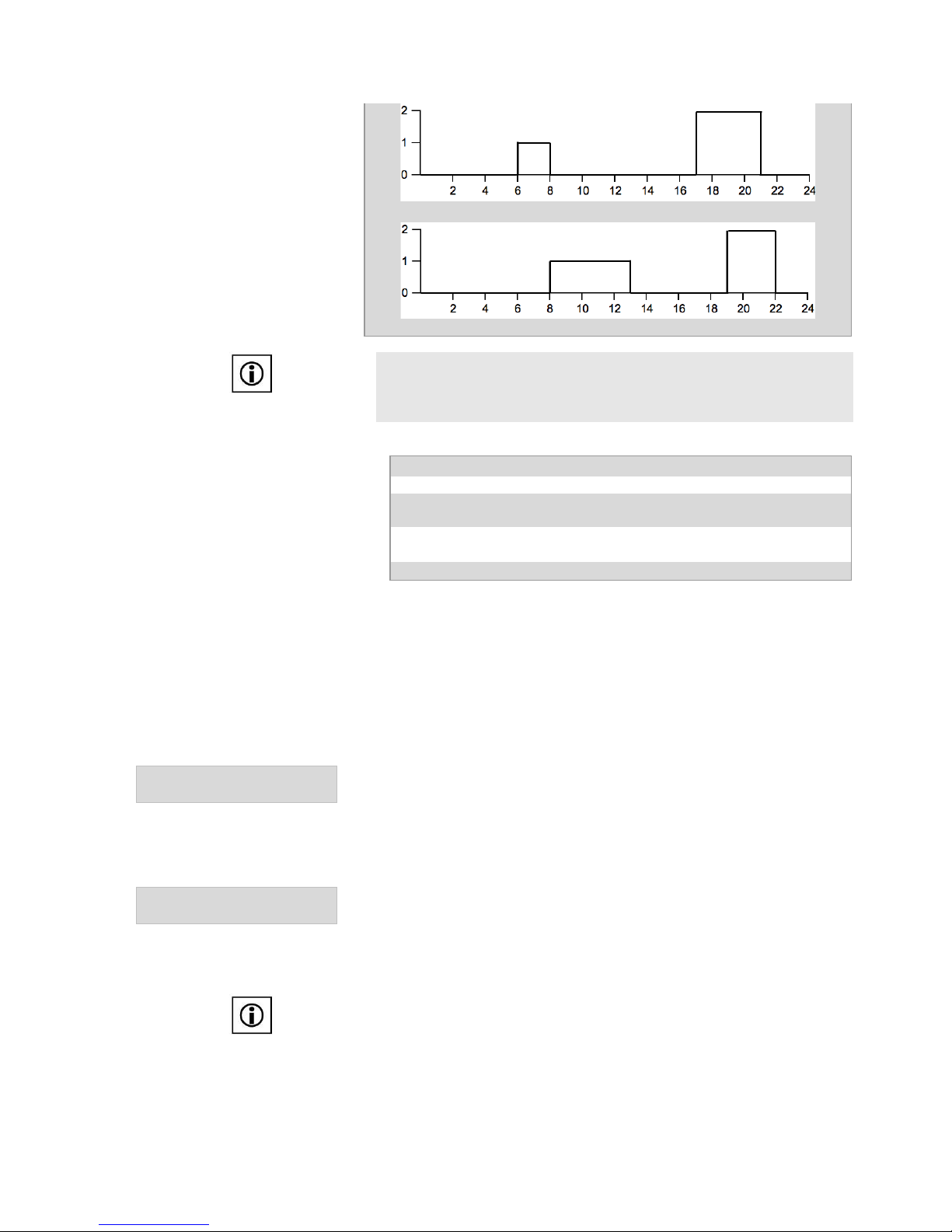
Example: DHW Heating - Weekday / Weekend
Timer:
Times
Switching Status
Mo-Fr Switching time 1:
06:00 hr
On (1)
Mo-Fr Switching time 2:
08:00 hr
Off (0)
Mo-Fr Switching time 3:
17:00 hr
Comfort (2)
Mo-Fr Switching time 4:
21:00 hr
Off (0)
Sa-So Switching time 1:
08:00 hr
On (1)
Sa-So Switching time 2:
13:00 hr
Off (0)
Sa-So Switching time 3:
19:00 hr
Comfort (2)
Sa-So Switching time 4:
22:00 hr
Off (0)
The hot water heating takes place from Monday to Friday during the hours of
6 – 8 and 17 – 21 and on the weekend between 8 – 13 and 19 – 22 (with
the later time periods being at the extra comfort temperature). During the off
periods the store will be maintained at the minimum temperature required.
Page 22
TDMA CONTROL 602-702 Eng Nov.doc
22
Monday to Friday
Saturday & Sunday
Note:
In Variant B (CONTROL 602) the boiler control in “Set Heating” can be set to
‘Auto + DHW or just DHW. The menu options in: Set Hot Water” are retained
and the output “Boiler On / Off” switches at the DHW’s request.
Hot Water Heating: Allocation Input – Function - Output
Input
Function
Store Sensor Top (Supplied)
Timed DHW Heating
Button
Timed control of extra comfort of
DHW heating
Output: DHW-heating, Boiler On/Off
5.6.2 Time Controlled Hot Water Circulation
The time controlled hot water circulation can save a lot of energy without
sacrificing comfort. The circulation pump can be connected into a bath button
and a built-in timer will be activated. If the bath button (circulation and bath
button, see section 5.6.1) is operated, the circulation pump is switched on for
the set time.
9#6;':"7#?$%O'45%Z'$$#$F%
-#4&%%%%%%%%%%%(\\\)0%!#$\%
Here, the operating time of the circulation pump can be set. The running time
should be such that warm water is pumped around the circuit form the store to
the furthest tap.
After switching off the pump, there will be an interval break of 15 minutes.
During this period the pump will not run, even when the button is pressed.
9#6;':"7#?$*%%%
-#4&6*%%%%%%%%%%%%2$%S%2BB%
If the circulation time switch is turned “On”, the circulation occurs within the
specified time frames according to the programme chosen (circulation period /
interval periods). 6 switching times can be set.
The setting of the timer is decribed in Section 5.6.1.
Note:
Be aware of Legionella Regulations
Page 23
TDMA CONTROL 602-702 Eng Nov.doc
23
Example: Hot water circulation weekend / weekday
Circulation running time:
2 Minutes
Times:
Time
Switching Status
Mo-Fr Switching time 1:
06:00 hr
On (1)
Mo-Fr Switching time 2:
08:00 hr
Off (0)
Mo-Fr Switching time 3:
17:00 hr
On (1)
Mo-Fr Switching time 4:
21:00 hr
Off (0)
Sa-Su Switching time 1:
08:00 hr
On (1)
Sa-Su Switching time 2:
13:00 hr
Off (0)
Sa-Su Switching time 3:
19:00 hr
On (1)
Sa-Su Switching time 4:
22:00 hr
Off (0)
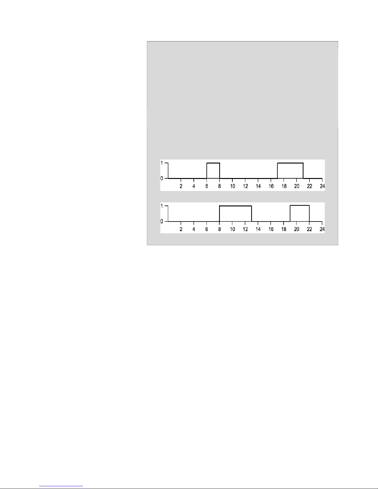
The circulation takes place from Monday to Friday during the hours 6 to 8
and 17 to 21 and on weekends from 8 to 13 and 19 to 22. Here, the pump
runs for 2 minutes with an interval break of 15 minutes. Outside this period,
the pump only runs when you press the button.
Monday to Friday
Saturday to Sunday
Page 24
TDMA CONTROL 602-702 Eng Nov.doc
24
5.7 Functions to operate the heating, the heating circuit
and heating support
5.7.1 Set Heating
!"#$%!&$'%%%%%%%%%%%%%%%%%%%%%%%%%%%%%%%%%()*+,%
>&7%@&"7#$F%%
The setting of the heating can be set here.
>7"67%@&"7%H"G%
2'7D\%-&45*%%%%%%%%%%%%%%%%%%%%%%%%%%%%0\\,0%19%
When the outdoor temperature exceeds the set “Start Heat Day Outd. Temp.”,
the heating is switched off (heaing circuit pump = off and mixing valve = close).
At 2 K below this temperature, the controller will turn the heating back on.
If a setback temperature is enabled, the “Start Day Outd. Temp.” will only be
active outside the setback periods.
>7"67%@&"7%M#FK7*%
2'7D\%-&45*%%%%%%%%%%%%%%%%%%%%%%%%%%0\\,0%19%
A similar action occurs at night as for the day, as mentioned above.
C6?87%O6?7&;7#?$*%
2'7D\%-&45*%%%%%%%%%%%%%%%%%%%%%%%Q(0\\\c(0%19%
If the outdoor air temperature drops below the Frost set point temperature
value, the heating independently of the operating mode (Auto heating + DHW
(winter) / Only DHW (summer) / Holiday) will switch on. When the heating is
switched off, the selected minimum flow temperature (flow temp. min.) is
adjusted.
H"G%>&7U";T*%%
%%%%%%%%%%%%%%%%%2$%S%2BB%
M#FK7%>&7U";T*%%%
%%%%%%%%%%%%%%%%%2$%S%2BB%
During either the day or night, the room temperature can be setback to a lower
temperature, rather than having the heating turned off. The length of time for
this set back temperature either during the day or night is adjustable.
M#FK7%>&7U";T*%%
P";K%H"G%S%PL&6G%H"G%S%A&&T&$DQ
A&&TD"G%
The setting of the timer occurs as described in Section 5.6.1
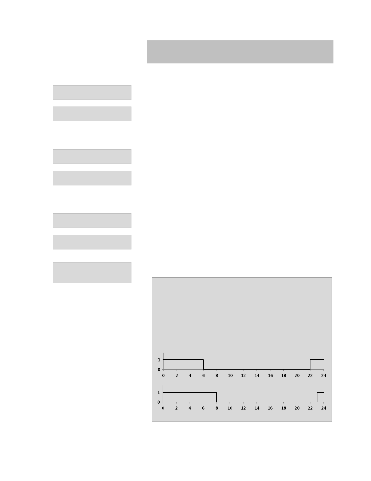
Example: Night Setback
Night Setback enabled:
On
Timer:
Weekday/Weekend
Weekday On (1):
22:00 hr
Weekday Off (0):
6:00 hr
Weekend On (1):
23:00 hr
Weekend Off (0):
8:00 hr
Room temperature Night
16 °C
The night set back is from 22:00 to 06:00 Monday to Friday and 23:00 to
08:00 Saturday & Sunday The room temp is lowered to the preset value.
Monday - Friday
Saturday - Sunday
Page 25
TDMA CONTROL 602-702 Eng Nov.doc
25
O"67G%>]#7;K*%%
%%%%%%%%%%%%%%%%%2$%S%2BB%
If the Party switch is set to “On” during the night or day setback periods, the
temperature setback is delayed until the party switch is set to “Off” again. If
the Party switch is not deactivated, the night setback waits until the following
night before coming active again.
The Party switch can also be activated by the TR-CONTROL. (see section
5.16.4)
See Technical Documentation on the TR-CONTROL for more information.
25&6"7#$F%!?D&*%%
='7?%K7F%c%H@A%S%H@A%?$:G%
Only DHW (Summer): The boiler and heating circuit pumps are switched off.
DHW heating is in operation. The heating circuit is active only for frost
protection.
Auto htg + DHW (Winter): Heating circuit pump, boiler and DHW heating in
operation. The heating circuit is active for frost protection.
Note:
Be aware of Legionella Regulations
5.7.1.1 Settings for a connected TR_CONTROL II Touch
Z??4%>&$8?6%
=;7#L&*%%%%%%%%E&8%S%M?%
If the CONTROL 602/702 and a TR-CONTROL II Touch are installed, then the
integrated room temperature sensor in the TR-CONTROL can be activated.
Only one circuit can be present in the reference room.
-Z%92M-Z2b*%
@7F\%"::?;"7#?$%
If the CONTROL 702 is to control multiple heating circuits, each having a TRCONTROL II Touch, then each circuit can be allocated against a TR-CONTROL.
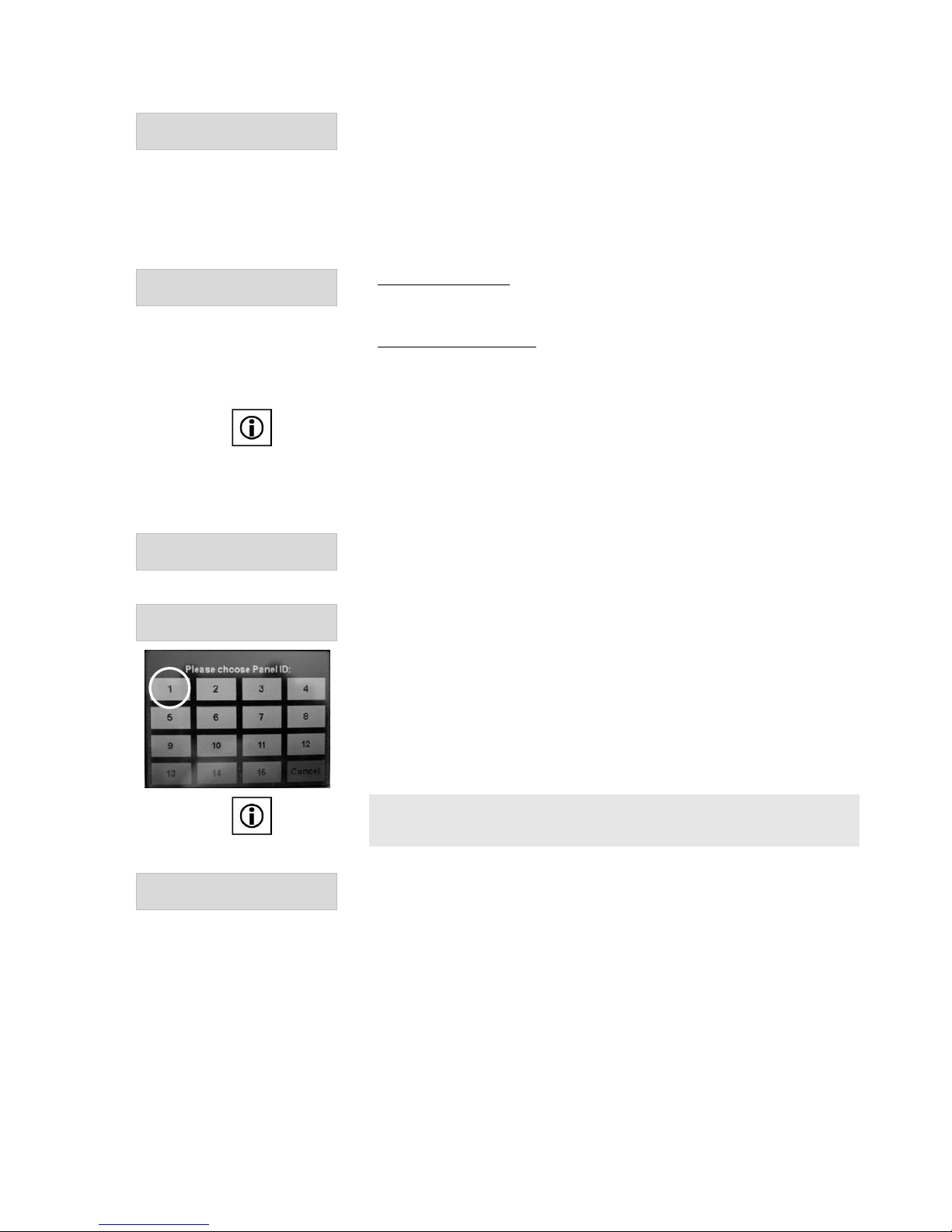
Assign a TR-CONTROL II Touch to each heating circuit: On start up of the TRCONTROL II Touch, press the screen where is says “Set ID”. You will get the
screen shown opposite. For Heating Circuit 1 press number 1, for Heating
Circuit 2 press 2, etc. The TR-CONTROL II Touch, after a few seconds revert to
the set time screen. Once this has bee set press the up key to go to main menu.
Note
The following 7 settings can be entered for each heating circuit (Set HC), as
long as each circuit has an active room sensor!
@&"7#$F%?BB%"7%0Y)0%T%"F"#$87%8&7%
6??4%7&45&6"7'6&%
Here the temperature difference between the actual room tenperature and the
target room temperature can be set. The boiler will then switch off and the
mixing valve closes. When a CONTROL 702 has several TR-CONTROL II
Touch’s connected, the controller will only shut off the boiler and the heating
pump when all the TR-CONTROL’s temperature differentials are met. The
hysteresis is factory set at 0.5 K
If a complete shutdown of the heating is not desired (eg. Set heating off at
20K) the system can still use the temperatures in the heating circuits during both
the day and night setback periods on the calculated flow temperatures to be
lowered.
Page 26

TDMA CONTROL 602-702 Eng Nov.doc
26
Example of CONTROL 602:
Room sensor active
Yes
Heating off at
1 K above room set temperature
Room temperature required:
20°C
When the room reaches 21 OC the controller will shut of the boiler, boiler
pump and heating circuit pump and closes the mixing valve.
For the CONTROL 702: With more than one TR-CONTROL Touch, the
boiler and boiler pump are only turned off when all the “heating off”
temperatures have been reached.
The heating is switched back on when the room reaches 20.5 OC.
-&45&6"7'6&%6#8#$F%"7*%
%%%%%%%%%%%%%%%%%0%Y%,0%19%
Here you set the room temperature, which is required on activation of
“temperature raising”.
-&45&6"7'6&%6"#8#$F%B?6*%
%%%%%%%%%%%%%%%0a[%Y%()%K%
Here you can set the time period for the how long you want the room
temperature to increase.
-&45&6"7'6&%:?]&6#$F%7?*%
%%%%%%%%%%%%%%%%0%Y%,0%19%
Here you can set the reduction in room temperature required.
-&45&6"7'6&%:?]&6#$F%B?6*%
%%%%%%%%%%%%%%%%0a[%Y%()%K%
Here you can set the time period for how long you want the room temperature
to decrease.
<&$7#:"7&%6??4%7&45&6"7'6&%7"6F&7*%%%%%%%%%%%
0Y%+0%19%
Here you can set the minimum room temperature at which the heating system
must switch on again.
A"::%9?66&;7#?$*%
%%%%%%%%%%%%%Q%(0%%c%(019%
Here you can correct the room temperature measurement.
Page 27

TDMA CONTROL 602-702 Eng Nov.doc
27
5.7.1.2 Screed Function
>;6&&D%H6G%C'$;7#?$%%
%%%%%%%%%%%%%%%%%2$%S%2BB%
This function allows the floor screed to dry by using the underfloor heating
circuits. The screed function is independent of the outside air temperature. It is
possible to enter up to 20 time intervals with different durations (shortest
duration 1 day) and different flow temperatures. A submenu allows you to
make the appropriate settings.
H&:"G%>7"67*%%
B?6*%%%%%%%%%%%0%%H"GI8J%
For a later start of the screed function, the time delay can be set here.
-#4&%d$7&6L":8%
%%%%%%%%%%%%%%%%%%%%%%0%
Depending on the screed size and construction, different time-temperature
curves for the drying process will be required. Here the number of time
intervals can be set.
d$7&6L":%H'6"7#?$%(%%
%%%%%%%%%%%%%%%%0%H"G8I8J%
Here the duration of interval 1 can be set.
d$7&6L":%(%C:?]%-&45&6"7'6&*%%%%%%%,[%
19%
The heating flow temperature for interval 1 can be set here.
Follow the above procedure for all the intervals:
>;6&&D%H6G%C'$;7#?$*%
>7"67*%%%%%%%%%%%E&8%S%M?%
This function can be started immediately.
After starting the programm the display will flash “screed function VL-Temp C”
with the respective flow temperature.
To stop the screed dry function at any time, turn the “screed Dry Function
Start” to No.
The number of power failures that occurred during the activated screed drying
function, can be read in the sub-menu.
Page 28
TDMA CONTROL 602-702 Eng Nov.doc
28
5.7.2 Set Heating Circuit
!"#$%!&$'%%%%%%%%%%%()*+,%
>&7%@9%
The flow temperature of the heating circuit is a function or outdoor
temperature. The heating curve slope can be adjusted depending on building
type and type of heating system. The CONTROL 602/702 calculates the
required flow temperature and operates the mixing valve to achieve this
temperature. The menu allows the following items to be adjusted individually.
For the CONTROL 602, the control of the heating circuit is only possible in
Variant B.
Z??4%-&45&6"7'6&*%
-"6F&7*%%%%%%%%%([\\\+0%19%
The preset room temperature is 20 °C. If a higher or lower room temperature
is desired, it can be set here.
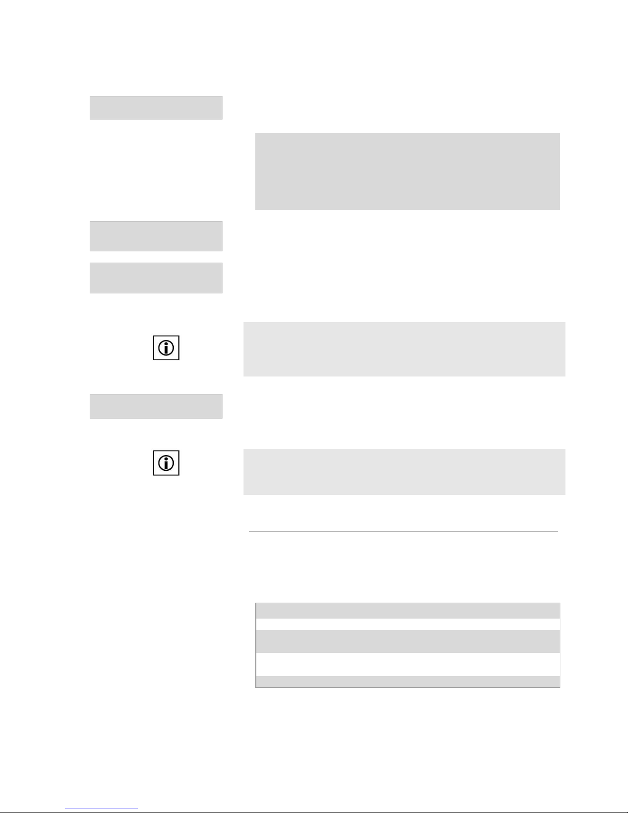
@&"7#$F%>:?5&*%
%%%%%%%%%%%%%%%0a+\\\,a,%
The heating slope required for the building location and flow temperature can
be set here.
Heating Slope
Flow Temperature °C
Slope
Example:
(1.) Location: Edinburgh (from
table below: -6 °C, high
thermal inertia building
without overload capacity)
(2.) Heating temperature:
Flow 60°C/ Return 40°C
(3.) From the diagram gives a
slope of heating of 1.4, which
is set on the controller.
External Temperature °C
External Tenperature for Various Locations
Low Thermal Inertia Building
High Thermal Inertia Building
Location
Overload Capacity
Without Overload
Capacity
With Overload
Capacity
Without Overload
Capacity
Birmingham
-5.0
-7.5
-3.0
-5.5
Cardiff
-3.0
-5.5
-1.5
-4.0
Edinburgh
-4.5
-7.0
-3.5
-6.0
Glasgow
-4.0
-6.5
-2.0
-4.5
London
-3.0
-5.5
-2.0
-4.5
Manchester
-3.5
-6.0
-2.5
-5.0
Plymouth
-1.0
-3.5
0.0
-2.5
Page 29
TDMA CONTROL 602-702 Eng Nov.doc
29
@&"7%9'6L&*%
%%%%%%%%%%%%%%%(a0\\\(a3%
The curviture of the curve is solely dependent on the type of heating system.
Example: Heating Curve
Underfloor Heating:
1,1
Column radiators made of cast iron or steel at normal
connection
1,3
Convector Heaters depending on Manufacturer:
1,3...1,6
C:?]%-&45%
!"R*%%%%%%%%%%%0\\\()0%19%%
Here the maximum flow temperature from the mixing valve can be set (eg.
Underfloor heating 40 oC)
C:?]%-&45*%
!#$*%%%%%%%%%%0\\\()0%19%%
Here the minimum flow temperature from the mixing valve can be set (eg,
Underfloor heating 30 oC).
Note:
With a defective external temperature sensor (open or short circuit), the
heating system will operate on frost protection (heating circuit pump = On and
flow temperature is set to ‘flow temp. Min.’ control)
@&"7#$F%!#R#$F%<":L&%%
Z&85?$8&%%%%%%%%%(\\\)00%
The heating mixing valve response is preset to 100 (for Consolar mixing
valve). This valve will change, either higher or lower, depending on
Manufcturer.
Note:
The larger control parameter entered, the quicker the deviation from the target
temperature will be corrected. However, using a parameter setting which is to
high can lead to the correct target temperatures not being achieved
Safety Function to Prevent the Mixing Valve or the Heating Circuit Pump sticks:
The controller opens and closes the mixing valve and turns on the heating
circuit pump for 30 seconds on a daily basis. This protective function is
activated when the heating circuit pump has been switch off for longer than 24
hours.
Heating circuit: Input Allocation – Function - Output
Input
Function
External Air Temperature Sensor
(Art. Nr. RE 046)
Heating circuit flow temperature,
heating frost protection limit
Flow Sensor (Art. Nr. RE 046)
Heating circuit flow temperature,
Winter switch
Output: Heating circuit pump and mixing valve
Page 30
TDMA CONTROL 602-702 Eng Nov.doc
30
5.7.3 Return Temperature Raising
!"#$%!&$'%%%%%%%%%%%()*+,%
>&7%@&"7#$F%
The CONTROL 602 / 702 has an adjustable temperature differential control,
which allows ‘Return Temperature Raising’ to be implemented. ‘Return
Temperature Raising is only possible in the CONTROL 602 with Variant A.
In the summer mode (DHW only) the ‘Return Temperature Raising’ function is
disabled.
H#BB\%Z&7'6$%-&45*%
C:?]%%%%%%%%%%%%%%)\\\),%.%
The temperature difference by which the temperature of the heating return can be
set here. The thermal store temperature must be higher than the return flow
temperature by this set amount to activate this function (switching the divert valve
from AB to A). The hysteresis is factory set at 2 K.
Note:
For the function ‘Return Temperature Raising’ the setting in Section 5.2 must be
considered.
Temperature differential Switch:
Allocation Input - Function - Ouput
Input
Function
Store sensor (D) (Art. Nr. RE 046)
Return Temperature Raising
Return Temp. Raising
(Art. Nr. RE 046)
Return Temperature Raising
Switch to winter mode (Soalr
system)
Output: Return Temp Raising (divertor valve)
5.8 Functions required to operate boiler
(Set Boiler)
!"#$%!&$'%%%%%%%%%%%()*+,%
>&7%N?#:&6%
This menu item can be any settings that affect either the boiler (eg., oil or solid
fuel), the boiler pump or the store charging pump.
To control the boiler, select the ‘boiler control’ in the CONTROL 602 Variant B
(select function 2) and in the CONTROL 702 (additional function 1).
If a boiler and a boiler pump are to be controlled by the controller, set the
‘’pump control’ as following Control 602 (select function 3) and the CONTROL
702 (additional function 2).
5.8.1 Boiler (Oil, Gas, Pellets)
Depending on the hydraulic circuit, either the boiler pump or store charging
pump is driven. The assignment are as follows:
Control Setting
Automatic assignement of the hydraulic circuit
Buffer logic
With Boiler Pump
Return temp raising
With Store charging pump
No setting
With Store charging pump
N?#:&6%-&45&6"7'6&%%
!#$*%%%%%%%%%%%%0\\\/0%19%
Here the minimum boier temperature is set, at which the boiler or store charging
pump output (A2) is turned on.
Page 31

TDMA CONTROL 602-702 Eng Nov.doc
31
N?#:&6%-&45&6"7'6&%%
!"R*%%%%%%%%%%%%%[0\\\X0%19%
Here the maximum boiler temperature can be set. The boiler (burner) is switched
off by the potential-free contact or via the 0-10V interface.
N?#:&6%H#BB&6&$7#":%
!"R*%%%%%%%%%%%%0\\\\30%.%
Heating: Here is calculated the temperatre difference between the heating
setpoint + differential buffer logic (if buffer logic is enabled) and sets the actual
boiler temperature. If the boiler actual temperature is higher than this
temperature differential, the burner switces off.
Hot Water Heating: The temperature difference between the hot water target
temperature and the actual boiler temperature is set here. When the actual
boiler temperature is higher than the target temperature by this set amount th
buner will switch off.
Example: Boiler heating
Heating circuit target temperature:
50 °C
Hot water temperature setpoint:
55 °C
Max Boiler differential:
15 K
If during hot water back up heating operation the bopiler reaches a
temperature of 70 °C, the boiler will switch off. During the heating
operation, the boiler will switch off at 65 °C. However, when the buffer
logic function is activated (Buffer logic differential 6 K), the boiler will switch
off at 71 °C.
N?#:&6%d$5'7*%%
(%_%>7&5%
With this function, the boiler (depending on design) 1-step, modulating or
temperature setpoint delivery can be controlled.
1-Step: The boiler is switched on and off via the potential-free contact.
N?#:&6%d$5'7*%
!?D':"7&D%
Modulated: A voltage of between 0 to 10 V controls the boiler. The output
voltage is dependent upon the temperature difference between actual and
desired temperature of the boiler The modulation is carried out by the CONTROL
602/702. Witht eh CONTROL 602, the modulation of the boiler control system
can only be used in Variant A.
The electrical connections are made in accordance with Section 6.2.3.3. or
7.2.4.3.
The following 6 menu items for the modulation of the boiler control are only
found in the Engineer’s menu.
Note:
If ‘Modulation’ has been set – no speed control of the store charging pump or
boiler pump can be made.
!#$*%%%%%)\\\[0%TA%
N?#:&6%2'75'7%
Here the minimum boiler output for modulating for modulating control can be set.
!"R*%%%%%)\\\[0%TA%
N?#:&6%2'75'7%
Here the maximum boiler output for modulating control can be set.
0%<*%%%%%0\\\[0%TA%
N?#:&6%2'75'7%
At this point the minimum boiler output corresponding to the 0 V value could be
set.
Page 32
TDMA CONTROL 602-702 Eng Nov.doc
32
(0%<*%%%%)\\\[0%TA%
N?#:&6%2'75'7%
At this point the maximum boiler output corresponding to the 10 V could be set.
O%QO"6"*%%%0\\\[0\0%
9?$76?:%O"6"4&7&68%
The P & I (tn) parameters of the 0 to 10 V output can be set here.
-$*%%%0\\\[00a0%>&;%
9?$76?:%O"6"4&7&68%
It is recommended not to change the preset parameters.
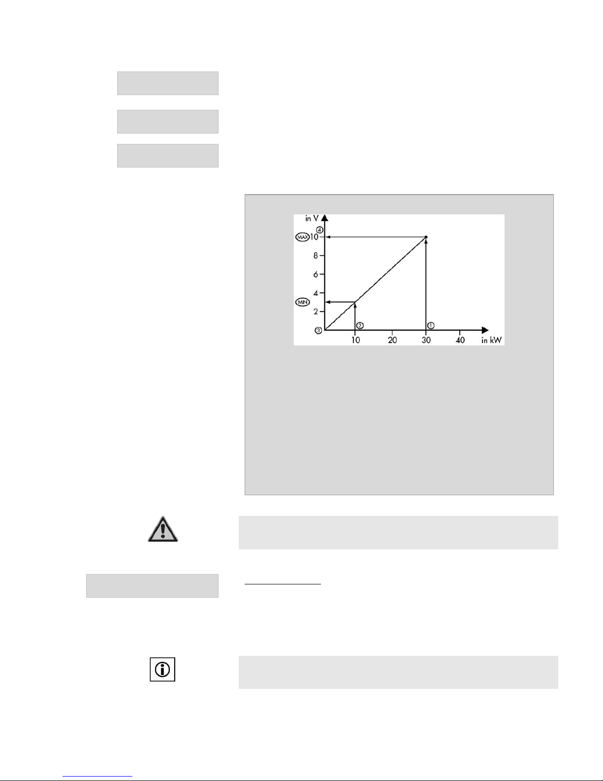
Example: Condensing Boiler – Giega Star from Giersch
(1) Boiler Output max:
30 kW
(2) Boiler Input min:
10 kW
(3) 0V:
0 kW
(4) 10V:
30 kW
P-Para:
10
I-Para:
15s
Ifthe boiler target temperature is either exceeded or not achived, the capacity
of the boiler output will be decreased or increased until the target temperature
is reached.
Attention
The modulation boiler control is only suitable with boilers who can be modulated
via 0-10 V output and do not independently modulate on their own.
N?#:&6%d$5'7%
-&45&6"7'6&%-"6F&7%
Temperature Target: The CONTROL 602/702 transmits the calculated target
temperature via a voltage between 0-10 v using the control on the boiler. This
processes the voltage signal and modulates the boiler automatically to the
desired temperature. The modulation is done by the boiler conrtroller.
The following two menu items appear only in the Engineer’s menu with a boiler
operating with ‘Temperature Target’.
Note:
When setting ‘Temperature Target’, no speed control of store charging pump or
boiler pump can occur!
Page 33
TDMA CONTROL 602-702 Eng Nov.doc
33
(%<*%%%%%%%%%(0%19%
2'75'7%-&45%*%
At this point, the target temperature can be set for 1 V (Boiler off = 0V).
(0%<*%%%%%%%(00%19%
2'75'7%-&45%*%
At this point, the target temperature can be set for 10 V.
O'45%-G5&%
87"$D"6DS%0Q(0LS%5]4%
The type of pump used is set here.
For a PWM pump 1 kHz = 10V
O'45%>5&&D%
4#$*%%%%%%%%%%%%%%%(00%`%
Here the minimum speed of the pump can be set. The speed of the boiler or
store charge pump is controlled, so that the desired temperature is reached at
the boiler. The speed of the boiler or store charge pump is always set at 100%
when the boiler is operating in a modulating capacity.
Note
If the boiler is set for modulating control or a temperature target – no speed
control of the boiler pump or store charge pump can occur!
!#$#4'4%H'6"7#?$*%
N?#:&6*%%%%%%%0\\30%4#$\%
Here the minimum duration of the boiler operation can be set, although the
maximum allowable boiler temperature will still activate the boiler safety shutoff
2L&66'$%-#4&*%%
N?#:&6%O'45%%%%0\\)0%4#$%
Here the overrun time of the boiler pump can be set.
2L&66'$%-#4&*%
>7?6&%O'45*%%%%0\\)0%4#$%
Here the overrun time of the Store Charge Pump is set.
Note
For the control of the boiler, the rules of the boiler manufacturer must be
observed.
Boiler Control: Allocation Input - Fuction - Output
Input
Function
Boiler sensor
(Art. Nr. RE 046)
Maximum temperature
Minimum temperature
Boiler/Store pump
Output: Boiler On/Off, Boiler /Store Pump
5.8.2 Solid Fuel Boiler Pump
The ‘Solid Fuel Boiler’ function can be used to provide the on/off control of the
solid fuel boiler pump. A temperature differential and minimum temperature
requirements are set, from which both conditions must be met before the pump
is started.
>?:#D%C'&:%N?#:&6*%%
-&45*%%%4#$*%%%+0\\W0%19%
When the solid fuel boiler sesnors reaches the minimum temperature, the ‘Solid
Fuel Boiler’ function is activated. The solid feul boiler pump runs until the
minimum temperature is exceeded by 2 K (hysteresis set at factory).
Page 34
TDMA CONTROL 602-702 Eng Nov.doc
34
H#BB\%>?:#D%C&':%N?#:&6*%
>CNQ>7?6&*%%%%%%)\\),%%.%
With this function, the temperature difference can be adjusted to maintain the
temperature at which the solid feul boiler sensor must be higher than the
temperature of the store sensor, so that the solid feul boiler is switched on.
The hysteres of 2 K has been set at the factory.
N?#:&6%2BB%#B%>?:#D%C'&:%N?#:&6%#8%2$%%%%%
E&8SM?%
If this function is set to ‘Yes’, then the boiler (oil, gas) is turned off when the
solid feul boiler is running.
Solid Fuel Boiler Control: Allocation Input - Function - Output
Input
Function
Solid Fuel Boiler Sensor
(Art. Nr. RE 046)
Minimum Temperature
Solid Fuel Boiler Differential
Store Temp Sensor - Solid Fuel
Boiler (Art. Nr. RE 046)
Solid Fuel Boiler Differential
Output: Solid Fuel Boiler Pump
5.8.3 Buffer logic
This function enables the boiler to be switched off when the buffer region of
the thermal store has reached the heating target temperature, whether this has
been achieved from solar energy or byusing the boiler.
The buffer logic controls the boiler operation in relation to the external
temperature. The additional ‘Lower buffer temperature sensor’ which is
situated below the ‘Upper buffer temperature sensor’ enables the boiler to run
longer in order to load the buffer region between these two temperature
sensors.
Note
The buffer logic function is activated in CONTROL 602, Variant B, and
Additional Function 8, while for the CONTROL 702 it is in Select Function 4.
H#BB&6&$7#":%N'BB&6%Q%%
:?F#;*%%%%%%%%%%%)\\),%.%
This function allows the temperature differential to be set. The temperature in
the buffer area.must be higher than the heating setpoint temperature to
activate the boiler on/off control
@G87&6&8#8%N'BB&6Q%%
:?F#;*%%%%%%%%%%(\\(0%.%
Here the hysteresis switching logic can be set.
Function: Buffer logic
The control switches the output depending on
Output Boiler On/Off
If both buffer temperature sensors are ≤ the
heating circuit flow temperature, plus the buffer
logic differential minus the hysteresis
Boiler On
Domestic hot water heating active
Frost protection active
If both buffer sensors are ≥ the heating circuit
flow temperature plus buffer differential
Boiler Off
Heizgrenzen überschritten
Page 35

TDMA CONTROL 602-702 Eng Nov.doc
35
Example: Buffer Logic
Heating Circuit setpoint temperature:
50 °C
Upper Buffer Sensor:
48 °C
Lower Buffer Sensor
42 °C
8K
Buffer Logic Hysteresis:
5K
When both buffer temperature sensors reach a temperature of 58 oC, the
boiler contact opene and switches off the boiler. When the temperature
falls to 53 oC (50 + 8 – 5) or less the boiler contact close and the boiler
switches on.
5.9 T-PRO / T-PRO 2 / T-PRO 3
!"#$%!&$'%%%%%%%%%%()*+,%
>&7%-_OZ2%
The CONTROL 602 has 2 all-pupose temperature difference control capability,
which enable control of hrdraulic circuits of various types. The CONTROL 702
has 3 T-Pro’s. Since the settings are identical, only that of the T-Pro will be
explained in more detail.
-&45&6"7'6&%>&$8?6%)%
%%%%%%%%%%%%%%%%%E&8%S%M?%
If the ‘Temperature sensor 2’: No’ option is set, the the T-PRO will function as
one temperature switch..
H#BB&6&$7#":%
-QOZ2%%%%%%%%%%%%0\\\+0%.%
The temperature differential can be adjusted so that the temperature at sensor
1 (source) must be higher than the temperature at sensor 2 (sink), so that the
T-PRO function is activated.
@G87&6&8#8%%
-QOZ2%%%%%%%%%%%%0\\\+0%.%
To prevent the contact switching continuously on and off, the switch hysteresis
is set here.
-&45&6"7'6&%%
!#$%%%%%%%%%%%%%0\\\(00%19%
The minimum and maximum temperatures for T-PRO sensors 1 and 2 can be
set.
-&45&6"7'6&%
!"R%%%%%%%%%%%%0\\\(,0%19%
2L&66'$%%
-QOZ2*%%%%%%%%0\\\30%4#$%
The T-PRO function will turn off after the preset overrun time has expired.
-#4&6%%
-QOZ2*%%%%%%%%%%%%E&8SM?%
If the timer is set to ‘Yes’, the T-PRO will only be active between the selected
time limits.
-QOZ2*%
PL&6GD"GS=::%H"GSA&&TD"GQ
A&&T&$D%
Thet timer settings are described in Section 5.6.1
Page 36
TDMA CONTROL 602-702 Eng Nov.doc
36
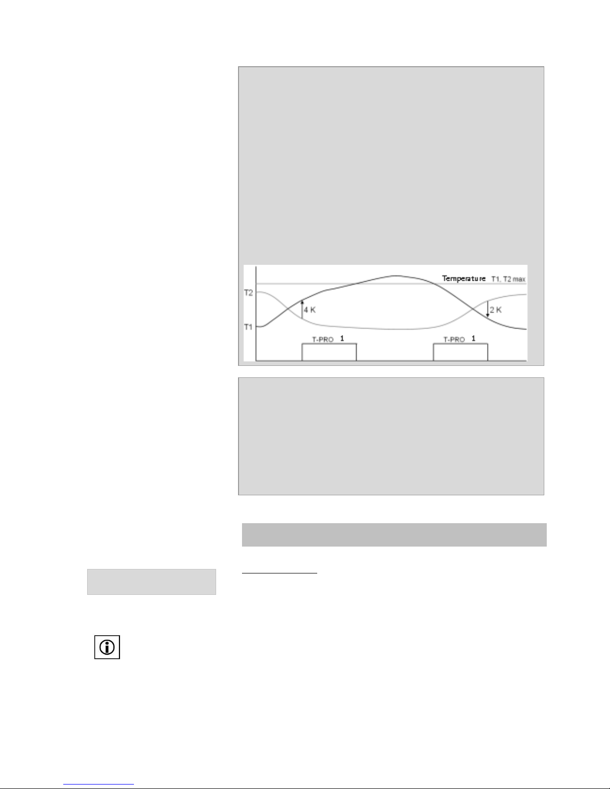
Example: Differential Temperature Control
Temperature sensor T2:
Yes
Differential T-PRO:
4K
Hysteresis T-PRO:
2K
Temperature T1 min:
50 °C
Temperature T1 max:
90 °C
Temperature T2 min:
50 °C
Temperature T2 max:
90 °C
Timer T-PRO:
On
T-PRO On 1:
08:00 hr
T-PRO Off 1:
16:00 hr
If the temperature at T1 is higher than T2 by 4k, the contact will close. If the
temperature of T1 falls back to within 2K of T2 the contact opens. If the
temperature exceeds the max temperature the contact opens and if it falls
below the minimum value the contact closes. This feature is only active
between 08:00 and 16:00.
Example: Temperature Switch
Temperature Sensor T2:
Nein
Temperature T1 min:
55 °C
Temperature T1 max:
60 °C
Overrun T-PRO
2 Minuten
If the temperature at temperature sensor T1 is lower than the preset
temperature of 55°C, the contact will close. When the temperature rises to
60°C, at sensor T1, the contact will open after the set overrun time of 2
minutes.
5.10 Holiday function
@?:#D"G*%
%%%%%%%%%%%0%Y%(00%H"GI8J%%
Holiday Operation: For the number of days set the heating circuit pumps,
boiler and DHW back-up heating is switched off. The frost protection function
remains active.
The holiday function can be found in the mainmenu options.
At low ambient temperatures, the home could become cold, therefore ensure
the holiday mode is turned off. In winter, if necessary, the minimum heating
flow temperature can be raised.
If the number of days is set to 0, all the systems that were switched off are
activated again. The flashing message ‘Active Holiday Function’ indictes the
holiday function is active.
Page 37
TDMA CONTROL 602-702 Eng Nov.doc
37
5.11 Service Menu
!"#$%!&$'%%%%%%%%%%()*+,%
>&6L#;&%
9?$8?:"6%%%9?$\%30)%%%%%%=55*%%%%%%%%%%<0\\%
)[\%(%
In this and the next item, the controller software version (App…….) along with
the system and basic software versions can be read.
>G87&4%%%%%%%<3\(+\)%%%%%%N"8#8%%%%%%%%<0\)3%
-#4&%%%%%%%%%%%%%%()*+,%
@68%S%!#$%%%%%%%%%%c%S%Q%
The time of the controller clock can be adjusted by using the - and + keys. The
hours are changed first and are set by pressing theconfirmation key . The
minutes can then be set.
Note
Time and date will continue to record for up to 2 hours following a power
failure. After that time the clock must be reset.
H"7&%
H"G%%%%%%%%%%%%%(\0(\)0((%
The date on the controller can be set here. With - and + keys you set the year
first and after confirmation with pressing the , you can then change the
month followed by the day.
>'44&6SA#$7&6*%%%%%%%%%='7?%7#4&*%%%%%%%%
E&8SM?%
You can set whether the controller will automatically select either summer or
wintertime.
9:?;T%9":#U6"7#?$*%
%%%%%%%0%a%(%%%4#$%S%!?$7K%
The time fields are set by which the clock should be calibrated monthly.
>&6L#;&%-&:%M?\%
d$5'7%
The telephone number of the service/installation company can be entered,
which will appear automatically in the display in the event of a fault occurring.
>&6L#;&%-&:%M?\%
0()+,[3/WX00000%
With the keys and the cursor can be navigated by the number row. The
key can select numbers or spaces. If the phone number entered is complete,
it should be confirmed with .
C";7?6G%>&77#$F*%%%
Z&87?6&V%%
Will restore the factory settings if confirmed with . The controller will reset
all values enter to those set in the factory (Variant A in 602).
Warning!
With ‘Factory Settings’ all setting will be overwritten. The controller must then
be re-programmed.
e5D"7&*%%%%%%%%%%%%%%M?%
d$5'7%
A software update can be performed (see Section 0).
Page 38
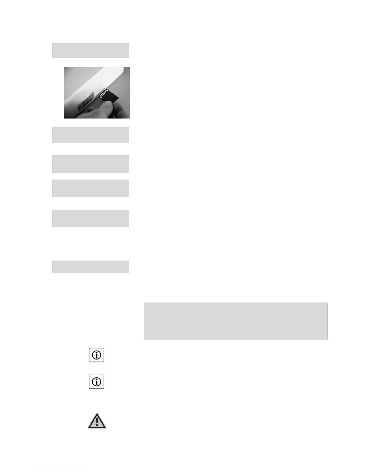
TDMA CONTROL 602-702 Eng Nov.doc
38
>H%_%Z&;?6D#$F%
>7"7'8*%%%%%%%%%%%%%%2$%
If the Sd recoding status ‘On’ is selected, the controller records, as soon as an
SD card is put into the controller, all measured values automatically. Also all
temperature values and output states will be recorded.
It is recommended that an SD Card is left in the controller and recording, so
that in case of a failure the cause can be found from the data recorded.
d$7&6L":*%%%%%%%%%%%(%0%8%
>H%Q%Z&;?6D#$F%
The time interval between the readings that the SD card will record.
>&77#$F8%%%
>"L&V%
The complete settings (selected system variant with all customer specific
adjustments) are saved to the SD card.
>&77#$F8%%%
e5:?"DV%
Saved settings / configerations can be uploaded. This can be useful for
programming errors or for firmware updates.
>&6L#;&%!&$'*%
P7K&6$&7%d$5'7%
The IP address for the controller can either be set or read. Ifthe DHCP state:
On is selected, the controller will automatically assign an IP address when the
controller is on a network.
The remore portal MAC address, which is required for registration, can be
found here.
!"$'":V%%
%
Here all outputs can be switched manually.
The settings in manual mode have priority over everything else. This means
that the pumps, or mixing valves can be switched on or off, even if the function
is turned off, in another menu, or even if in a fault condition.
Example: Manual Mode of Solar Pump
On: The solar pump is switched on permanently.
Off: The solar pump is switched off.
Auto: The controller controls the pump according to the state of the system.
Note
If the DHW back-up heating and the boiler functions are activated manually to
‘On’ they switch back to ‘Auto’ operation after 10 minutes automatically.
Note:
Choosing Open, Close, Off or Auto can operate the mixing valve manually.
In the Open, Close or Off positions, the mixing valve will remain in that
position permanently until the control is switched back to Auto. You should
therefore always set it to Auto.
Caution
The manual switching (manual operation) must only be used in short periods or
for testing purposes only. Continual running in manual mode will damage the
system or components, because the safety functions are overridden.
Page 39
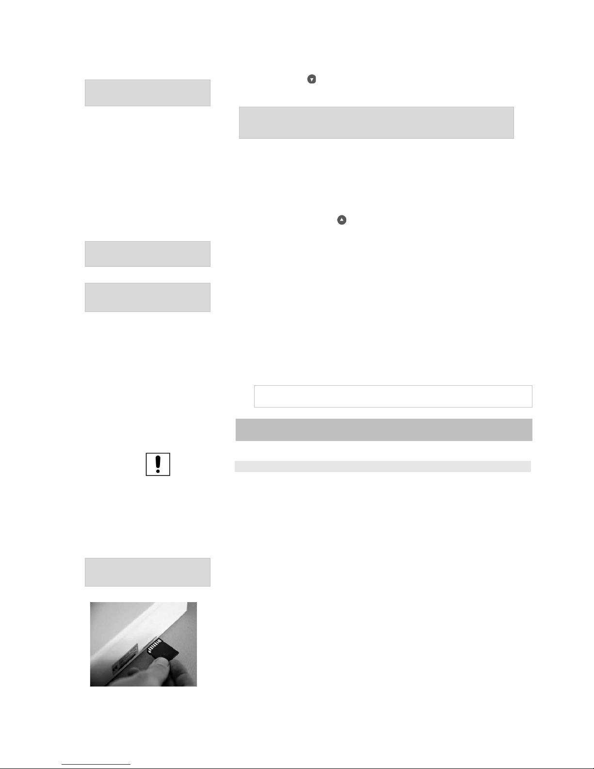
TDMA CONTROL 602-702 Eng Nov.doc
39
2'75'7%<#&]V%
%
By confirming with the outputs appear as follows:
View of CONTROL 602:
(%%%%+%%%%[%%%%/%%%%!%(%*%00a0%<%
)%%%%,%%%%3%%%%W%%%%!%)%*%00a0%<%
With the CONTROL 702 the outputs are shown in two views (View 1 = output
1 to 19, View 2 = Output M1 to M6).
If an output is switched on the corresponding number will change to a ,
whilst for unswitched outputs the display shows a symbol. The outputs that
require a 0-10V voltage are displayed along side the corresponding M
symbol. With pressing the key you will be returned to the service menu.
>&:&;7%b"$F'"F&%
P$F:#8K%
The language used can be selected here from English, German, French and
Italian.
='7K?6#8"7#?$*%
>&7V%
The professional menu can be access by using the code number 3003.
30 minutes after the last input, the controller automatically locks the
professional menu.
By inputing 0000, the professional menu is locked..
5.12 Software Update via SD-Card
Note:
A software update is only possible in the professional menu.
Any new controller software must be stored on the SD Card under a folder
called ‘Firmware”. This allows the controller to locate the software.
The settings made in the web portal such as data recording, graphical views,
may need to be re-set after a firmware update. It is recommended that the
data is saved prior to the update.
='7K?6#8"7#?$*%
>&7V%
The Engineer’s menu is found by inputing the cose 3003 in the authorised to
set option.
Insert the SD-Card into the slot provided on the side of the controller (see
photo). When the controller detects the SD Card, an SD Card icon appears in
the display window.
Located on the SD Card in the ‘Firmware’ folder is a control software that
matches the controller, the controller asks whether a software update is to be
performed.
Page 40

TDMA CONTROL 602-702 Eng Nov.doc
40
e5D"7&*%%%%%%%%%%%%%%%M?%
O&6B?64V%
Confirm with Yes and to activate.
The controller switches to the basic system and displays a list of the possible
controller software versions.
=L"#:"U:&%C#64]"6&%Qf%%% %%
92M-Z2b%30)%%<(\00%
%%%92M-Z2b%30)%%<(\0)%%%%%%%%%%%%%%%%%%%%%%%%%
Selection of the software via and . Confirm the software and start the
updates with .
The controller automatically makes a backup of the control software. The
controller automatically installs the selected software.
Page 41
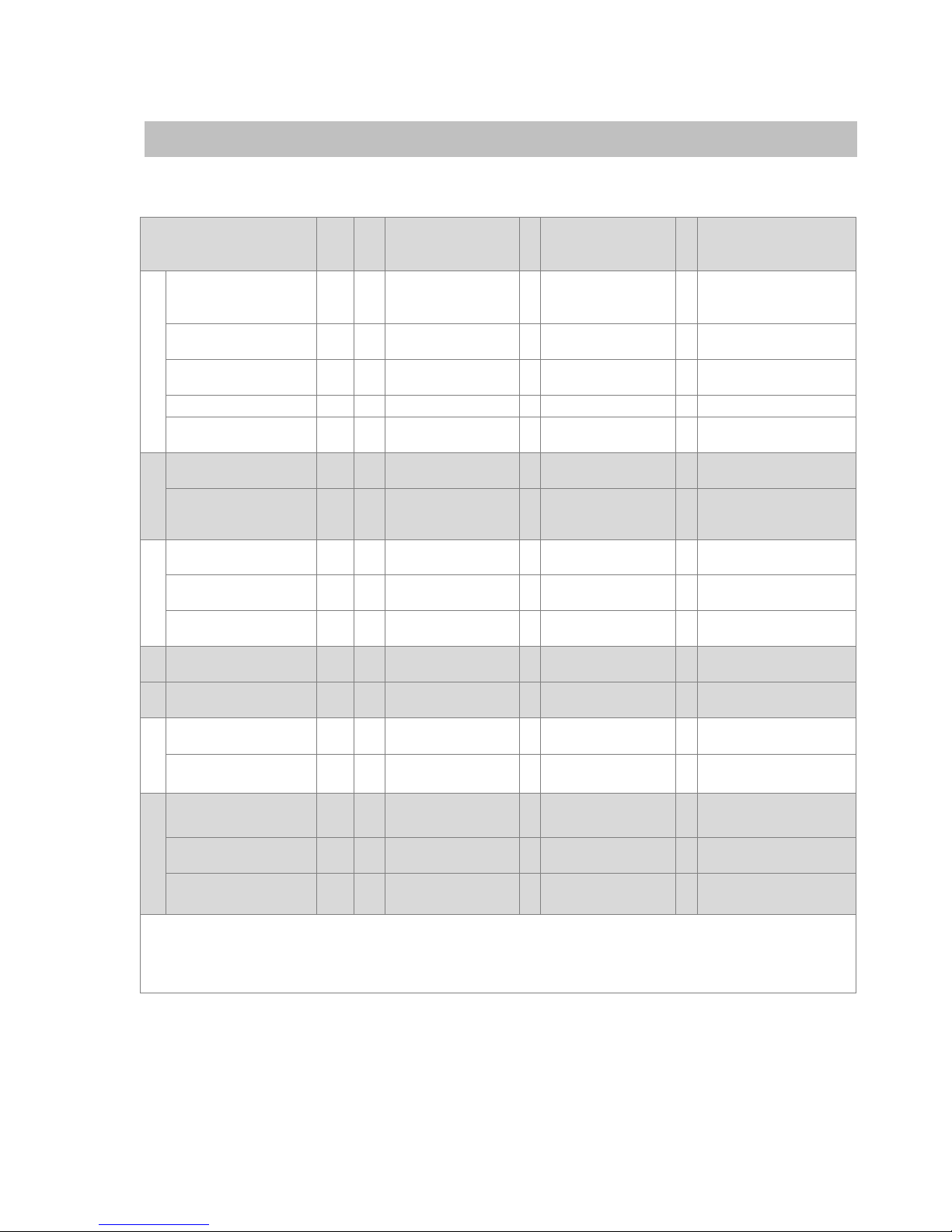
TDMA CONTROL 602-702 Eng Nov.doc
41
5.13 CONTROL 602: Example Variant A
Function
Sele
ction
Sub
sect
ion
Cannot be
combined with
F
Sensor allocation
A
Output
allocation
Solar pump with and
without top loading
X
BF
- 1 2
3
Collector sensor
Store bottom (F)
Store top (A; B)
1
Collector pump
230
V
** East-West
V
SF 2 Active frost
protection, cooling
8
Collector sensor 2
3
Collector pump
2
230
V
Yield Measurement
AF
1
-
4 5 Yield sensor (cold)
Yield sensor (hot)
- -
Radiation measure
AF - ES
Radiation sensor
- -
Solar
Frost protection
SF
2
East-West, cooling
8
Frost sensor
1
Collector pump
230
V
Cooling
AF
2
- 3 Store top (A; B)
2
Cooling
230
V
Cooling
* Two store (Priority
or Equal) pool**
SF 2 East-West,
Frost protection
8
Store 2 bottom;
Pool sensor
2
Cooling
230
V
DHW heating
AF
3
- 3 Store top (A; B)
8
DHW heating
230
V
Circulation
AF
4
- - -
5
Circulation
pump
230
V
Hot water
Circulation with bath
button ***
SF
3
Heat meter 1
- - D1
Bath button
Return temperature
raising
V
SF 1 T-Pro,
Solid fuel boiler
9
10
Heating return
store sensor (C)
4
Return temp
raising
230
V
Solid fuel boiler
SF 1 Return temp
raising, T-Pro
9
10
Solid fuel boiler
Store sensor (E)
4
Solid fuel boiler
230
V
T-Pro
SF 1 Return temp raise,
Solid fuel boiler
9
10
T-Pro sensor 1
T-Pro sensor 2
4
T-Pro
230
V
T-Pro
T-Pro 2
AF
6
-
6 7 T-Pro 2 sensor 1
T-Pro 2 sensor 2
6
T-Pro 2
230
V
Heat meter 1
SF 3 Circulation with
bath button
D1
Heat meter 1
- -
Heat meter 2
SF 4 Yield measurement
flow meter
D2
Heat meter 2
- -
Heat Sensing
Flow meter for Yield
measurement
SF
4
Heat meter 1
D3
Flow meter (solar
return line)
- -
BF = Basic func tion (always active); AF…AF8 = Additional function (need activating); SF1…SF6 = Select function
(one function can be activated); A, B, C, D, E and F : Sensor sleeve position SOLUS II; *Cooling is possible
only if selected, ** East-West a nd Swimming pool cannot be activated together, ***Only when circulation
function and hot water heating are activated with a separate output.
Page 42
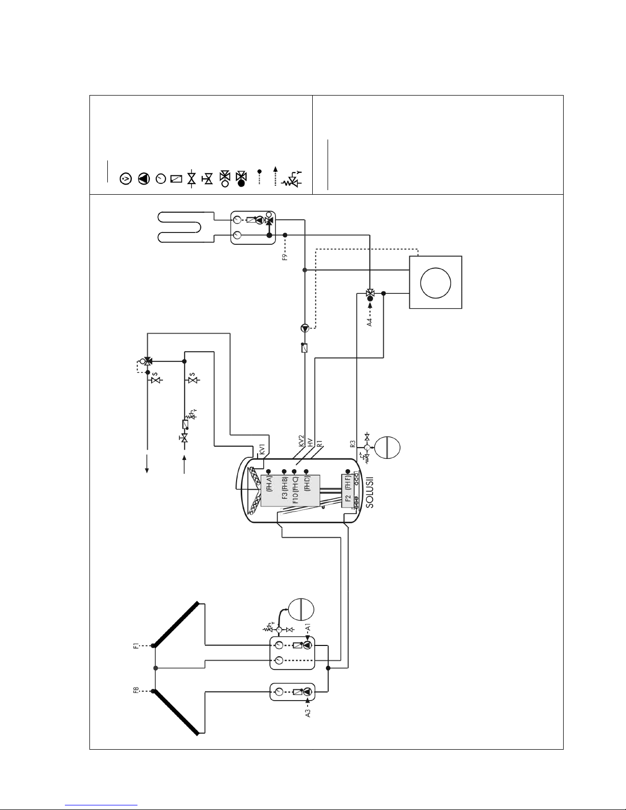
TDMA CONTROL 602-702 Eng Nov.doc
42
5.13.1Hydraulic Circuit example CONTROL 602 Variant A
Flow Meter
Pump Analoge Thermometer Non Return Valve Flushing Valve Stop Valve Mixing Valve Diverting Valve Temperature Sensor CONTROL Outputs Safety Valve
Control Settings:
Variant: A
Additional Func 1: No
Function
Additional Func 2: No
Function
Additional Func 3: No
Function
Additional Func 4: No
Function
Additional Func 6: No
Function
Additional Func 7: No
Function
Select Func 1: Return Temp
Raising
Select Func 2: East/ West
with 2 Pumps
Select Func 3: No Function
Select Func 4: No Function
Legend
Page 43
TDMA CONTROL 602-702 Eng Nov.doc
43
System Variant
Recommended Value:
Setting:
Variant
A
Stratisification Function
Auto
Additional Function 1
Yield
Additional Function 2
Application Dependent
Additional Function 3
Application Dependent
Additional Function 4
Application Dependent
Additional Function 6
Application Dependent
Additional Function 7
Application Dependent
Select Function 1
Application Dependent
Select Function 2
Application Dependent
Select Function 3
Application Dependent
Select Function 4
Application Dependent
Solar max via:
Yield Sensor
DHW Heating back-up via
Control:
1
Application Dependent
Solar Input:
Recommended Value:
Setting:
Solar Differential
6...12 K
Solar Differential 2
2
6...12 K
Switch to Winter
3
25 °C
Store Top max
90 °C
Cooling Temperature
4,5
85 °C
Cooling Hysteresis
4,5
5 K
Changeover
Temperature
6,7,8
85 °C
Changeover Hysteresis
6,7,8
5 K
Swimming Pool max
8
25 °C
Solar Collector Start
Application Dependent
Frost Protention Overrun
9
Application Dependent
Water Input10:
Recommended Value:
Setting:
DHW Temperature Setpoint
55 °C
DHW Temp Hysteresis
5 K
DHW Back-up Htg Overrun
4 Min.
DHW Back-up Min Temp
Application Dependent
DHW Heating Optimised
User Dependent
DHW Extra Comfort
65 °C
DHW Heating Timer
On
To Engineer’s Menu?
DHW Back-up Heating
User Dependent
Switching Time1
User Dependent
Switching Time 2
User Dependent
Switching Time 3
User Dependent
Switching Time 4
User Dependent
Switching Time 5
User Dependent
Switching Time 6
User Dependent
Water Input11:
Recommended Value:
Setting:
Circulation Run Time
User Dependent
Circulation Timer
On
To Engineer’s Menu?
Circulation
User Dependent
Switching Time 1
User Dependent
Switching Time 2
User Dependent
Switching Time 3
User Dependent
Switching Time 4
User Dependent
Switching Time 5
User Dependent
Switching Time 6
User Dependent
Input Calc. Values:
Recommended Value:
Setting:
Anti-Freeze Type
12
Propylen
Anti-Freeze Concentration
12
Application Dependent
Solar Flow Rate
12, i
Application Dependent
Heat Meter Value
13
Application Dependent
Heat Meter Setting
12, 13
Application Dependent
Volumetric Flowmeter
14
Application Dependent
Heating Input:
Recommended Value:
Setting:
Return Flow Differential
1
6 K
Screed Function
Off
Boiler Input:
Recommended Value:
Setting:
Solid Fuel Boiler Temp.min
50 °C
Solid Fuel Boiler Differential
6 K
Input T-PRO15:
Recommended Value:
Setting:
Temperature Sensor 2
Application Dependent
Differential T-PRO
Application Dependent
Hysteresis T-PRO
Application Dependent
Temperature T1 min
Application Dependent
Temperature T1 max
Application Dependent
Temperature T2 min
Application Dependent
Temperature T2 max
Application Dependent
T-PRO Overrun
Application Dependent
Use T-PRO Timer?
Application Dependent
to Engineer’s Menu?
T-PRO Timer
Application Dependent
Switching Time 1
Application Dependent
Switching Time 2
Application Dependent
Switching Time 3
Application Dependent
Switching Time 4
Application Dependent
Input T-PRO 216:
Recommended Value:
Setting:
Temperature Sensor 2
Application Dependent
Differential T-PRO
Application Dependent
Hysteresis T-PRO
Application Dependent
Temperature T1 min
Application Dependent
Temperature T1 max
Application Dependent
Temperature T2 min
Application Dependent
Temperature T2 max
Application Dependent
T-PRO Overrun
Application Dependent
Use T-PRO Timer?
Application Dependent
To Engineer’s Menu?
T-PRO Timer
Application Dependent
Switching Time 1
Application Dependent
Switching Time 2
Application Dependent
Switching Time 3
Application Dependent
Switching Time 4
Application Dependent
Service:
Recommended Value:
Setting:
Consolar Con. 602 App
Software Version
Basic
Basic Version
Time
Current Time
Date
Current Date
Automatic Switching
Summer/Winter Time
Yes
Clock Calibration
Application Dependent
Service Tel.-Nr. Setting
Application Dependent
Restore factory Settings
No
Interval of SD Card
Recordng
60 s
Ethernet Input
User Dependent
DHCP state
IP Address
Sub-network
Gateway Address
MAC Address
Manual Control
Auto
View Outputs
Select Language
User Dependent
Authorised Set
User Dependent
!"#$%&'%()*+%
,-%.)*/0"%1)23)04*/0)%.4&(&"5% % % % 6-%708(*%908*):*&8"%
;-%<4(*%=%>)(*% % % % % ,?-%@A>%A)4*&"5%
B-%C*04*&'&:4*&8"%7/":*&8"%=%D/*8% % % % ,,-%E&0:/#4*&8"% % E8"*8##)0%C)0&4#%F8GGGGGGGGGGGGG-%
H-%E88#&"5% % % % % % ,;-%I&)#J%
K-%E88#&"5%/(&"5%A)4*&"5%E&0:/&*%,% % % ,B-%A)4*%L)*)0%
M-%1N8%C*80)%90&80&*$% % % % % ,H-%O8#/2)%7#8N2)*)0%
P-%1N8%C*80)%<Q/4#% % % % % ,K-%1R9.!%
S-%CN&22&"5%988#% % % % % ,M-%1R9.!%;%
%F8*)+%
When using a flow meter set the solar flow to 0 l/min on the controller.%
Page 44
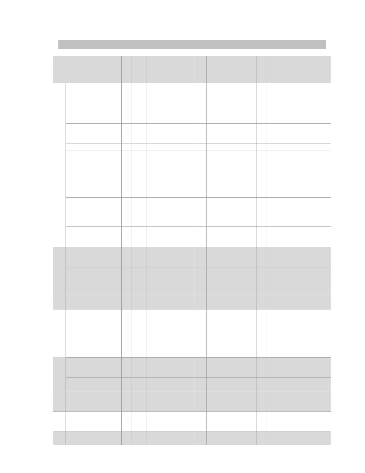
TDMA CONTROL 602-702 Eng Nov.doc
44
5.14 CONTROL 602: Example Variant B
Function
Se
lec
tio
n
Sub
secti
on
Cannot be
combined with
F
Sensor allocation
A
Output
allocation
Solar pump with
and without top
loading
X
BF
- 1 2
3
Collector sensor
Store bottom (F)
Store top (A; B)
1
Collector pump
230V
*
3
East-West
V
SF 1
Active frost
protection,
cooling
9
Collector sensor
2
4
Collector pump
2
230V
Yield Measurement
SF 1
East-West, T-Pro,
Solid Fuel Boiler
9
10
Yield sensor
(cold)
Yield sensor (hot)
- -
Radiation measure
AF - ES
Radiation sensor
- -
Frost Protection
SF 2
Cooling via
Heating Circuit,
Two Store,
Boiler Control
8
Frost Protection
Sensor (Coldest
Point)
1
Collector pump
230V
Cooling
SF 3
DHW Back-up
Htg, Circulation,
Pump Control
3
Store Top (A; B)
2
Cooling
230V
Two Store *1
(Priority, Equal
Priority), Swimming
Pool
SF 2
Frost Protection,
Cooling via
Heating Circuit,
Boiler Control
8
Store 2 Bottom;
Swimming Pool
Sensor
2
Cooling
230V
Solar
Cooling via
Heating Circuit *
2
SF 2
Frost Protection,
Two Store,
Boiler Control
3
Store Top (A; B)
2 5 Cooling
Heating Circuit
230V
DHW Heating with
Separate Output
SF 3
Cooling,
Circulation,
Pump Control
3
Store Top (A; B)
2
DHW Back-up
heating
230V
Circulation
SF 3
Cooling,
DHW Back-up
Heating, Pump
Control
-
Without Sensor
2
Circulation
Pump
230V
DH Water
Circulation with
Bath Button *4
SF 5
Heat Meter 1
D1
Bathroom Button
- -
Boiler Control for
DHW and Heating
V
SF 2
Frost Protection,
Two Store,
Cooling via
Heating Circuit
8 3 Boiler Sensor
Store Top (A; B)
8
Boiler Control
0-
10V
Boiler
Pump Control for
Boiler and Store
V
SF 3
Cooling,
Circulation,
DHW Back-up
3
Store Top (A; B)
2
Boiler/ Store
Pump
230V
1 Heating Circuit /
Mixing Valve and
Pump Control
V
SF 4
1 Heat PI
6
7
Htg Flow Sensor
Ambient Air
Temp
5
6
7
Heating Pump
Mixing Vv Close
Mixing Vv Open
230V
Buffer Logic
V
AF 8
-
4 5 Buffer Top (C)
Buffer Bottom (D)
- -
Heating Support
Solid Fuel Boiler
SF 1
East-West, T-Pro,
Yield
Measurement
9
10
Solid Fuel Boiler
Store SFB (E)
4
Solid Fuel Boiler
230V
T-Pro
SF 1
East-West, Yield
Measurement,
Solid Fuel Boiler
9
10
T-Pro 1
T-Pro 2
4
T-Pro
230V
t
Se
ns
in
g
Heat Meter 1
SF 5
Circulation/Bath
Button
D1
Heat Meter 1
- -
Page 45

TDMA CONTROL 602-702 Eng Nov.doc
45
Heat Meter 2
SF 6
Yield Flow
D2
Heat Meter 2
- -
Solar Yield Flow
Measurement
V
SF 6
Heat Meter 2
D2
Volumetric Flow
Meter (Solar
Flow )
- -
BF = Basic Function (always active); AF…AF8 = Addittional Function (Activate); SF1…SF6 = Select Function (One
function can be activated); A, B, C, D, E and F: Sensor sleeve position on the SOLUS II; *
1
Cooling is possible
only when set, *
2
Only possible with heating circuit *
3
East-West a nd Swimming pool cannot be activated
togther, *
4
Only possible when circulation and boiler controls are activated.
Page 46
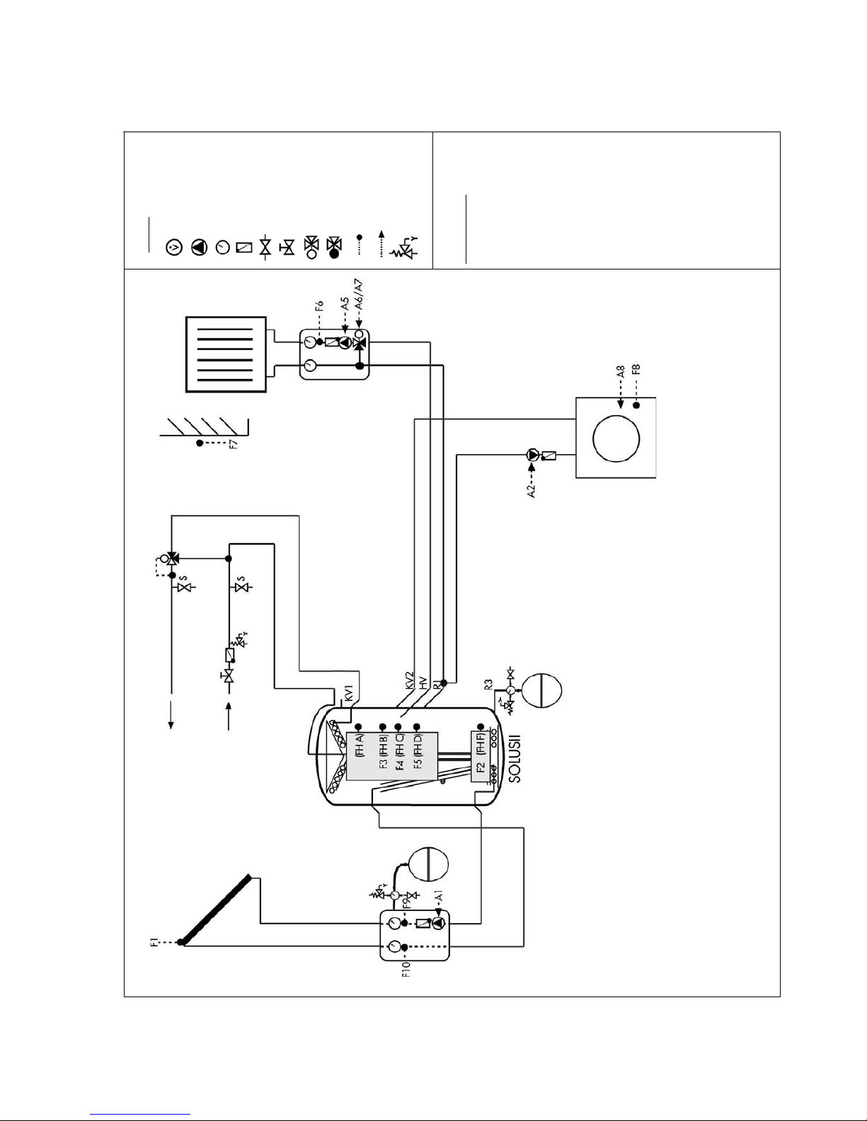
TDMA CONTROL 602-702 Eng Nov.doc
46
5.14.1 Sample Circuit for CONTROL 602 Variant B
Flow Meter Pump
Analoge Thermometer Non Return Valve
Flusing Valve
Stop Valve Mixing Valve Diverting Valve
Temperature Sensor CONTROL Outputs Safety Valve
Control Settings:
Variant: B
Additional Func. 7:No
Function
Additional Func. 8: Buffer
Logic
Select Func. 1: Yield
Select func. 2: Boiler Control
Select func. 3: Pump Control
Select Func. 4: Heating Circuit
Select Func. 5: No Function
Select Func. 6: Flow Meter
Legende
Page 47

TDMA CONTROL 602-702 Eng Nov.doc
47
System Variant
Recommended Value
Sttings
Variant
B
Stratification Function
Auto
Additional Function 7
Application Dependent
Additional Function 8
Application Dependent
Select Function 1
Application Dependent
Select Function 2
Application Dependent
Select Function 3
Application Dependent
Select Function 4
Application Dependent
Select Function 5
Application Dependent
Select Function 6
Application Dependent
Solar max via:
Application Dependent
Solar Input:
Recommended Value
Settings
Differential Solar
6...12 K
Differential Solar 2
1
6...12 K
Switch to Winter
2
25 °C
Store Top max
90 °C
Cooling Temperature
3,4
85 °C
Hysteresis Cooling
4,5
5 K
Changeover Temperature
5,6,7
85 °C
Hysteresis Changeover
6,7,8
5 K
Swimming Pool max
8
25 °C
Solar Collector Start
Application Dependent
Frost Protection Overrun
8
Application Dependent
Water Input10
Recommended Value
Settings
DHW Set-point Temperature
55 °C
DHW Heating Hysteresis
5 K
DHW Heating Overrun
4 Min.
DHW Heating Min Temp
Application Dependent
Optimised DHW Heating
User Dependent
DHW Priority
Application Dependent
DHW Extra Comfort
65 °C
DHW Heating Timer
On
To Engineer’s Menu?
DHW Back-up Heating
User Dependent
Switching Time 1
User Dependent
Switching Time 2
User Dependent
Switching Time 3
User Dependent
Switching Time 4
User Dependent
Switching Time 5
User Dependent
Switching Time 6
User Dependent
Water Input11:
Recommended Value
Settings
Circulations Run Time
User Dependent
Circulation Timer
On
To Engineers’s Menu?
Circulation
User Dependent
Switching Time 1
User Dependent
Switching Time 2
User Dependent
Switching Time 3
User Dependent
Switching Time 4
User Dependent
Switching Time 5
User Dependent
Switching Time 6
User Dependent
Input Calc. Values:
Recommended Value
Settings
Anti-Freeze Type
12
Propylen
Anti-Freeze Concentration
12
Application Dependent
Solar Flow Rate
12, i
Application Dependent
Heat Meter Value
13
Application Dependent
Heat Meter Setting
13
Application Dependent
Volumetric Flow Meter
12, 14
Application Dependent
Heating Input:
Recommended Value
Settings
Day outside temp htg limit
15
22 °C
Night outside temp htg limit.
15
18 °C
Frost protection temp limit.15
4 °C
Day Set-back
15
On
To Engineer’s Menu?
Room Temp – Day
18 °C
Day Set-back
User Dependent
Switching Time 1
User Dependent
Switching Time 2
User Dependent
Night Set-back
15
On
Room Temp – Night
16 °C
Night Set-back
User Dependent
Switching Time 1
User Dependent
Switching Time 2
User Dependent
Party Switch
15
User Dependent
Operating Mode
15
Season Dependent
Minimum flow temperature
User Dependent
Screed Function
Off
Heating Circuit Input15:
Recommended Value
Settings
Desired Room Temperature
20 °C
Heating Curve Slope
See Technical Doc.
Heating Characteristic Curve
Application Dependent
Flow Temperature max
Application Dependent
Flow Temperature min
Application Dependent
Mixing Valve Control
Parameter
Application Dependent
Boiler Input10:
Recommended Value
Settings
Boiler Temperature min
System Dependent
Boiler Temperature max
System Dependent
Differential Boiler max
10 K
Boiler Input
Application Dependent
Boiler Output min
ii
System Dependent
Boiler Output max
ii
System Dependent
Boiler Output 0 V
ii
System Dependent
Boiler Output 10 V
ii
System Dependent
Control Parameter P
ii
Application Dependent
Control Parameter Tn
ii
Application Dependent
Pump Speed min
Application Dependent
Min Run Time of Boiler
2 Minutes
Boiler Pp Extended Running Time
Application Dependent
Difference Bufferlogic
16
Hysterese Bufferlogic
Solid Fuel Boier Temp.min
17
50 °C
Difference Solid Fuel Boiler
17
4 K
Boiler off if Solid fuel boiler on?
17
Application Dependent
T- PRO18 Input
Recommended Value
Settings
Temperature sensor 2
Application Dependent
Difference T-PRO
Application Dependent
Hysterese T-PRO
Application Dependent
Temperature T1 min
Application Dependent
Temperature T1 max
Application Dependent
Temperature T2 min
Application Dependent
Temperature T2 max
Application Dependent
Overrun T-PRO
Application Dependent
Timer T-PRO Use?
Application Dependent
To Engineer’s Menu?
Timer T-PRO
Application Dependent
Switching Time 1
Application Dependent
Switching Time 2
Application Dependent
Switching Time 3
Application Dependent
Switching Time 4
Application Dependent
Service:
Recommended Value
Settings
Consolar Con. 602 App
Software version
Basic
Basic version
Time
Current Time
Date
Current Date
Auto Switching Sum/Win time
Yes
Calibrate Clock
Application Dependent
Service Tel.-Nr. insert
Application Dependent
Restore Factory Settings
No
Interval SD-Recording
60 s
Ethernet Input
User Dependent
DHCP State
IP Address
Sub-Network
Gateway Address
MAC Address
Manual Operation
Auto
View Outputs
Language
User Dependent
Authorisation Set?
User Dependent
Controller Serial No………………………. Only if Set:
1
East-West
7
Swimming Pool
13
Heat Meter
2
Stratification Function ≡ Auto
8
Frost Protection
14
Volume Flow Meter
3
Cooling
9
DHW Heating
15
Heating
4
Cooling via Heating Circuit 1
10
Boiler Control
16
Bufferlogic
5
Two Store Priority
11
Circulation
17
Solid Fuel Boiler
6
Two Store Equal
12
Yield
18
T-PRO
Note:
i
When using a flow meter set the solar flow to 0 l/min on the controller.
ii
Only with modulated boiler operation must the parameters be set
Page 48
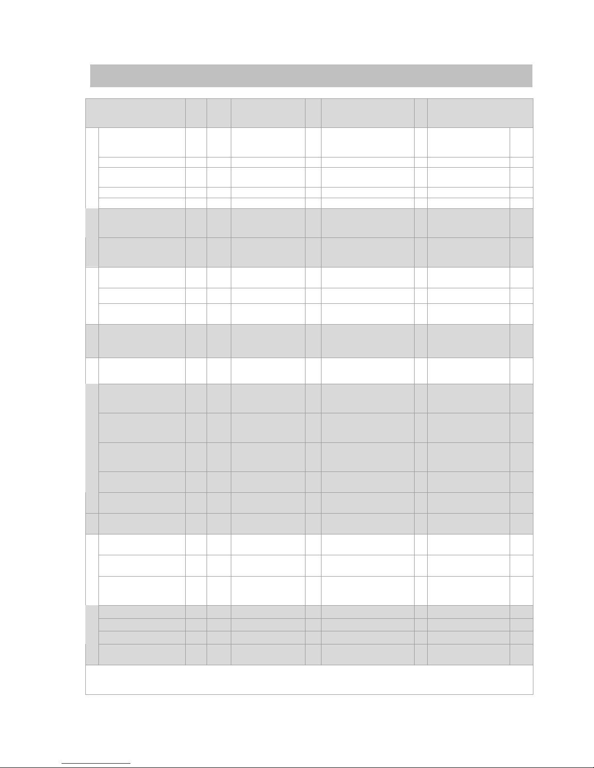
TDMA CONTROL 602-702 Eng Nov.doc
48
5.15 CONTROL 702: Example
Function
Sele
ctio
n
Subsecti
on:
Cannot be
combined with:
F
Sensor Allocation
A
Output Allocation
Solar pump with &
without top loading
X
BF
- 1 2
3
Collec tor Sensor
Store Bottom (F)
Store Top (A; B)
1
Collector pump
230V
East-West
SF 5 - 11
Collec tor Sensor 2
2
Collec tor pump 2
230V
Yield Measurement
AF 4
-
9
10
Yield Sensor (Cold)
Yield Sensor (Hot)
- -
Radiation Measure
AF 7 - ES
Radiation Sensor
- -
Solar Function
Frost Protection
AF 6 - 17
Frost Sensor
1
Collector pump
230V
* Twin Store
(Priority, Equal),
Swimming Pool
SF 6
-
3
15
Store top (A; B)
Store 2 Bottom
3
Cooling
230V
Cooling
** Cooling via
Heating Circuit
SF 6
Twin Store
(Priority, Equal),
Swimming Pool
3
Store Top (A; B)
9
10
11
Pump Heating circ 1
Mixer Close HC1
Mixer Open HC 1
230V
DHW Heating with
Separate Output
SF 7 - 3
Store Top (A; B)
18
DHW Heating
0-
10V
Circ ulation
AF 3 - - - 5
Circ ulation pump
230V
DHW
Circ ulation/ Bath
Button
BF - D2
- Digital Input 2
-
Circ ulation pump
230V
Boiler
Boiler Control for
DHW & Heating
AF 1
-
3
12
16
Store Top (A; B)
Boiler Sensor
Ambient Temperature
19
Boiler Demand
0-
10V
Htg
Pump Control for
Boiler & Heating
AF 2 - 12
Boiler Sensor
6
Boiler pump
230V
Heating Circ 1 /
Mixer Vv & Pump
Control
SF 1
-
6
16
Heating Flow 1
Ambient Temp Sensor
9
10
11
Pump Heating Cir 1
Mixer Close HC1
Mixer Open HC 1
230V
Heating Circ 2 /
Mixer Vv & Pump
Control
SF 2
-
7
16
Heating Flow 2
Ambient Temp Sensor
12
13
14
Mixer Close HC 2
Mixer Open HC2
Pump Heating Cir 2
230V
Heating Circ 3 /
Mixer Vv & Pump
Control
SF 3
-
8
16
Heating Flow 3
Ambient Temp Sensor
15
16
17
Mixer Close HC 3
Mixer Open HC3
Pump Heating Cir 3
230V
Bufferlogic
SF 4
Return Temp
Raising
4 5 Buffer Sensor 1
Buffer Sensor 2
- -
Heating Support
Return Temp Raising
SF 4
Bufferlogic
4 5 Heating Return
Store Heating Return
7
Return Temp Raising
230V
Solid Fuel Boiler
SF 8
T- Pro 2
13
14
Solid Fuel Blr Sensor
Store Solid Fuel Blr
8
Solid Fuel Boiler
230V
T- Pro
AF 5
-
18
19
T- Pro Sensor 1
T- Pro Sensor 2
4
T- Pro
230V
T- Pro 2
SF 8
Solid Fuel Boiler
13
14
T- Pro 2 Sensor 1
T- Pro 2 Sensor 2
8
T- Pro 2
230V
Temp.- Control
T- Pro 3
SF 7
DHW Heating
with Separate
Output
20
21
T- Pro 3 Sensor 1
T- Pro 3 Sensor 2
18
T- Pro 3
230V
Heat Meter 1
SF 9
Thermostat HC 1
D3
Digital Input 3
- -
Heat Meter 2
SF 10
Thermostat HC 2
D4
Digital Input 4
- -
Heat Meter 3
SF 11
Thermostat HC 3
D5
Digital Input 5
- -
Flowmeter for Solar
Output Measurement
BF D1
Digital Input 1
- -
BF = Basic func tion (always active); AF1…AF7 = Additional Function (activate); SF1…SF11 = Select Function (one
function can be activated); A, B, C, D, E and F: SOLUS II Sensor Sleeve Positions; *Only when Cooling is set,
**Only with activated heating circuit control.
Page 49
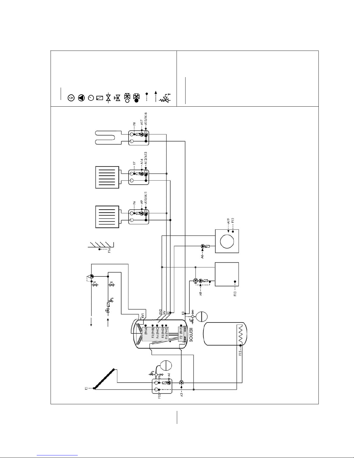
TDMA CONTROL 602-702 Eng Nov.doc
49
5.15.1 Sample Circuit for CONTROL 702 Boiler Buffering
Volume Flow Meter Pump Temperature Gauge
Non-Return Valve
Flushing Valve
Isolating Valve Miving Valve Diverting Valve Temperaturs Sensor
Inputs - CONTROL Safety Valve
Control Setting:
Additional Func. 1: Boiler
Control
Additional Func. 2: Pump
Control
Additional Func. 4: Yield
Select Func. 1: Heating
Circuit 1
Select Func. 2: Heating
Circuit 2
Select Func. 3: Heating
Circuit 3
Select Func. 4: Buffer Logic
Select Func. 6: Two Store
Priority
Select Func. 8: Soid Fuel
Boiler
Legend
Page 50
TDMA CONTROL 602-702 Eng Nov.doc
50
System Variant
Recommended Value
Setting
Stratification Function
Auto
Additional Function 1
Application Dependent
Additional Function 2
Application Dependent
Additional Function 3
Application Dependent
Additional Function 4
Application Dependent
Additional Function 5
Application Dependent
Additional Function 6
Application Dependent
Additional Function 7
Application Dependent
Select Function 1
Application Dependent
Select Function 2
Application Dependent
Select Function 3
Application Dependent
Select Function 4
Application Dependent
Select Function 5
Application Dependent
Select Function 6
Application Dependent
Select Function 7
Application Dependent
Select Function 8
Application Dependent
Select Function 9
Application Dependent
Select Function 10
Application Dependent
Select Function 11
Application Dependent
Solar max. via:
Application Dependent
Solar Input:
Recommended Value
Setting
Difference Solar
6...12 K
Difference Solar 2
1
6...12 K
Switch to Winter
2
25 °C
Store Top max
90 °C
Cooling Temperature
3,4
85 °C
Hysteresis Cooling
4,5
5 K
Changeover Temperature
5,6,7
85 °C
Hysteresis Changeover
6,7,8
5 K
Swimming Pool max
8
25 °C
Solar Collector Start
Application Dependent
Frost Protection Overrun
8
Application Dependent
Water Input
9,10
:
Recommended Value
Setting
DHW Set-point Temp.
55 °C
DHW Heating Hysteresis
5 K
DHW Heating Overrun
4 Min.
DHW Heating min Temp.
Application Dependent
Optimised DHW Heating
User Dependent
DHW Priority
Application Dependent
DHW Extra Comfort Temp.
65 °C
DHW Timer
On
To Engineer’s Menu?
WW-Nachheizung
User Dependent
Switchinh Time 1
User Dependent
Switchinh Time 2
User Dependent
Switchinh Time 3
User Dependent
Switchinh Time 4
User Dependent
Switchinh Time 5
User Dependent
Switchinh Time 6
User Dependent
Eingabe Wasser11:
Recommended Value
Setting
Zirkulationslaufzeit
User Dependent
Zirkulation Schaltuhr
EIN
To Engineer’s Menu?
Circulation
User Dependent
Switching Time 1
User Dependent
Switching Time 2
User Dependent
Switching Time 3
User Dependent
Switching Time 4
User Dependent
Switching Time 5
User Dependent
Switching Time 6
User Dependent
Input Calc. Values:
Recommended Value
Setting
Antifreeze Type
12
Propylen
Antifreeze Concentration
12
Application Dependent
Solar Flow Rate
12, i
Application Dependent
Rdiation Sensor
Application Dependent
Heat Meter 1 (D3) Value
13
Application Dependent
Heat Meter 1 (D3) Set
13
Application Dependent
Heat Meter 2 (D4) value
13
Application Dependent
Heat Meter 2 (D4) Set
13
Application Dependent
Heat Meter 3 (D5) Value
13
Application Dependent
Heat Meter 3 (D5) Set
13
Application Dependent
Volumetric Flow Meter
12, 14
Application Dependent
Heating Input:
Recommended Value
Setting
Frost Protection Temp.15
4 °C
Setting of Heat Circuits
User Dependent
Room sensor Active
Application Dependent
Input HC115:
Recommended Value
Setting
Day Outside Temp Htg Limit
15
22 °C
Night Outside Temp Htg Limit
15
18 °C
Desired Room Temperature
20 °C
Day Setback
15
On
To Engineer’s Menu?
Day Setback Room Temp.
18 °C
Switching Time 1
User Dependent
Switching Time 2
User Dependent
Night Setback
15
On
Night Setback Room Temp.
16 °C
Switching Time 1
User Dependent
Switching Time 2
User Dependent
Party Switch
15
User Dependent
Operating Mode
15
Season Dependent
Heating Curve Slope
See Technical Document
Heating Characteristic Curve
Application Dependent
Flow Temperature max
Application Dependent
Flow Temperature min
Application Dependent
Mixing Vv Control Parameter
Application Dependent
Input HC215:
Recommended Value
Setting
Day Outside Temp Htg Limit
15
22 °C
Night Outside Temp Htg Limit
15
18 °C
Desired Room Temperature
20 °C
Day Setback
15
On
To Engineer’s Menu?
Day Setback Room Temp.
18 °C
Switching Time 1
User Dependent
Switching Time 2
User Dependent
Night Setback
15
On
Night Setback Room Temp.
16 °C
Switching Time 1
User Dependent
Switching Time 2
User Dependent
Party Switch
15
User Dependent
Operating Mode
15
Season Dependent
Heating Curve Slope
See Technical Document
Heating Characteristic Curve
Application Dependent
Flow Temperature max
Application Dependent
Flow Temperature min
Application Dependent
Mixing Vv Control Parameter
Application Dependent
Input HC315:
Recommended Value
Setting
Day Outside Temp Htg Limit
15
22 °C
Night Outside Temp Htg Limit
15
18 °C
Desired Room Temperature
20 °C
Day Setback
15
On
To Engineer’s Menu?
Day Setback Room Temp.
18 °C
Switching Time 1
User Dependent
Switching Time 2
User Dependent
Night Setback
15
On
Ra Night Setback Room Temp.
16 °C
Switching Time 1
User Dependent
Switching Time 2
User Dependent
Party Switch
15
User Dependent
Operating Mode
15
Season Dependent
Heating Curve Slope
See Technical Document
Heating Characteristic Curve
Application Dependent
Flow Temperature max
Application Dependent
Flow Temperature min
Application Dependent
Mixing Vv Control Parameter
Application Dependent
Input Boiler10:
Recommended Value
Setting
Boiler Temperature min
Boiler Dependent
Boiler Temperature max
Boiler Dependent
Difference Boiler max
30 K
Boiler Input
Application Dependent
Boiler Output min
ii
Boiler Dependent
Page 51

TDMA CONTROL 602-702 Eng Nov.doc
51
Boiler Output max
ii
Boiler Dependent
Boiler Output 0 V
ii
Boiler Dependent
Boiler Output 10 V
ii
Boiler Dependent
Control Parameter P
ii
Application Dependent
Control Parameter Tn
ii
Application Dependent
Pump Speed min
Application Dependent
Min Run Time of Boiler
2 Minutes
Boiler Pp Extended Running Time
Application Dependent
Difference Buffer Logic
16
Hysteresis Buffer Logic
Solid Fuel Boiler Temp.min
17
50 °C
Difference Solid Fuel Boiler
17
4 K
Boiler off, if Solid Fuel Boiler on?
17
Application Dependent
Input T-PRO18:
Recommended Value
Setting
Temperature Sensor 2
Application Dependent
Difference T-PRO
Application Dependent
Hysteresis T-PRO
Application Dependent
Temperature T1 min
Application Dependent
Temperature T1 max
Application Dependent
Temperature T2 min
Application Dependent
Temperature T2 max
Application Dependent
Overrun T-PRO
Application Dependent
Timer T-PRO Use?
Application Dependent
To Engineer’s Menu?
Timer T-PRO
Application Dependent
Switching Time 1
Application Dependent
Switching Time 2
Application Dependent
Switching Time 3
Application Dependent
Switching Time 4
Application Dependent
Input T-PRO 218:
Recommended Value
Setting
Temperatur e Sensor 2
Application Dependent
Difference T-PRO
Application Dependent
Hysteresis T-PRO
Application Dependent
Temperature T1 min
Application Dependent
Temperature T1 max
Application Dependent
Temperature T2 min
Application Dependent
Temperature T2 max
Application Dependent
Overrun T-PRO
Application Dependent
Timer T-PRO Use?
Application Dependent
To Engineer’s Menu?
Timer T-PRO
Application Dependent
Switching Time 1
Application Dependent
Switching Time 2
Application Dependent
Switching Time 3
Application Dependent
Switching Time 4
Application Dependent
Input T-PRO 318:
Recommended Value
Setting
Temperature Sensor 2
Application Dependent
Difference T-PRO
Application Dependent
Hysteresis T-PRO
Application Dependent
Temperature T1 min
Application Dependent
Temperature T1 max
Application Dependent
Temperature T2 min
Application Dependent
Temperature T2 max
Application Dependent
Overrun T-PRO
Application Dependent
Timer T-PRO Use?
Application Dependent
To Engineer’s Menu?
Timer T-PRO
Application Dependent
Switching Time 1
Application Dependent
Switching Time 2
Application Dependent
Switching Time 3
Application Dependent
Switching Time 4
Application Dependent
Service:
Recommended Value
Setting
Consolar Con. 702 App
Software Version
Basic
Basic Version
Time
Current Time
Date
Current Date
Auto Switching Sum/Win Time
Yes
Calibrate Clock
Application Dependent
Service Tel. Nr. Insert
Application Dependent
Restore factory Settings
No
Interval SD-Recording
60 s
Input Ethernet
User Dependent
DHCP State
IP Address
Sub-network
Gateway Address
MAC Address
Manual Operation
Auto
View Outputs
Language
User Dependent
Authorisation Set?
User Dependent
Serial No…………………………..
Only if set:
1
East-West
10
Boiler Control
2
Stratification Function ≡ Auto
11
Circulation
3
Cooling
12
Yield
4
Cooling via Heating Circuit 1
13
Heat Meter
5
Two Store Priority
14
Volume Flow Meter
6
Two Store Equal
15
Hearing
7
Swimming Pool
16
Buffer logic
8
Frost Protection
17
Solid Fuel Boiler
9
DHW Heating
18
T-PRO
Note:
i
When using a flow meter set the solar flow to 0 l/min on the controller.
ii
Only with modulated boiler operation must the parameters be set.
Page 52
TDMA CONTROL 602-702 Eng Nov.doc
52
5.16 TR-CONTROL II Touch Special Features
The TR-CONTROL II Touch allows access to various functions (if programmed) by just
pressing the key whilst in the main menu screen (such as circulation button, party
button and extra comfort). These special functions can be found by pressing either the
/ keys and then the . You can turn on or off the function by pressing the + or
– keys and then pressing the key. If you turn one of the functions off, you are
asked ‘disable function really?’ by pressing the feature is turned off.
5.16.1 Circulation Button
The circulation pump can be activated on demand via the TR-CONTROL II Touch, by
pressing the key when in the main menu screen. To change the pump from off to On,
use the + or – keys and then confirm with the key. The circulation pump will run for
the allocated time (set Hot Water – Circulation Run Time).
This function is only possible if in Variants the circulation function is activated.
When the circulation pump run time has expired, it is locked for about 20 minutes. Re-
activation during this time is not possible. The display will show ‘Circulation Locked’
(gesperrt).
5.16.2 DHW Heating Extra Comfort Temperature
The DHW set-point temperature can be raised for a set period to an Extra Comfort
DHW Temperature level (within Set Hot Water function). If this function has been turned
on, then the hot water will be delivery at the raised temperature. If the store top
temperature cannot provide the required extra comfort temperature, the controller will
bring on the back up heating to raise the store top temperature. After the extra confort
temperature is reached the display will show Comfort at 65oC (or temperature chosen).
When the temperature has been reached a re-activation is not possible until the
temperature in the store top has fallen below the DHW heating Extra Comfort
Temperature (2K hysteresis).
This function can make a significant contribution to energy saving during off-peak
periods, where the reheating temperature can be set lower.
Even during the off-times the extra comfort temperature switch can still operate.
5.16.3 Ventilation
The heating circuit can be switched off briefly, when ventilation the house (ie by
opening the windows on a daily basis). When in the main menu, press the and then
until Ventilation is shown, then press + to change to ON then press to confirm.
This will switch off the heating pump and the mixer is left running. When the room
temperature falls below the Set Room Temperature the ventilation function is
automatically disabled and the heating goes back to normal. To disable the function
press the and the following message appears ‘Disable Function Really’. To confirm
press .
This function is only possible if the room sensor of the TR-CONTROL II Touch has been
enabled.
Notes for CONTROL 702
In setting ‘Individual setting of heating circuits: Inputing ‘Yes’ – The function is effective
only on the heating circuit, which the TR-CONTROL II Touch has been assigned.
Inputing ‘No’ – The function affects all heating.
Page 53
TDMA CONTROL 602-702 Eng Nov.doc
53
5.16.4 Party Switch
If heat is required during the night setback period, then pressing the Party Switch will
bring the heating back on. To do this press when in the main menu screen and
continue to press the until Party Switch appears on the screen, then press + followed
by which will change the Off to On. To revert back to normal operation, press the
which shows the following message ‘ Function Really Deactivate?’, to confirm press
. If you do not deactivate the Party Switch, the controller will naturally do this the
next time the night setback is required.
Notes for CONTROL 702
In setting ‘Individual setting of heating circuits: Inputing ‘Yes’ – The function is effective
only on the heating circuit, which the TR-CONTROL II Touch has been assigned.
Inputing ‘No’ – The function affects all heating.
5.16.5 Room Temperature Drop ….min to …oC
With this function, the ambient temperature of the room can be lowered. When
activated (press then until ‘Room Temp Drop’ is shown, then press to activate)
the room temperature is lowered for the duration set and to the preset temperature.
The setting values can be found in Set HC.
To deactivate this function press , a message will appear asking ‘Disable Function
Really?’ to confirm press and the function will be deactivated. (see Section 5.7.1)
5.16.6 Temperature Rise …Min at …°C
With this function, the ambient temperature of the room can be raised. When activated
(press then until ‘Room Temp Rise’ is shown, then press to activate) the room
temperature is raised for the duration set and to the preset temperature. The setting
values can be found in Set HC.
To deactivate this function press , a message will appear asking ‘Disable Function
Really?’ to confirm press and the function will be deactivated. (see Section 5.7.1)
Page 54
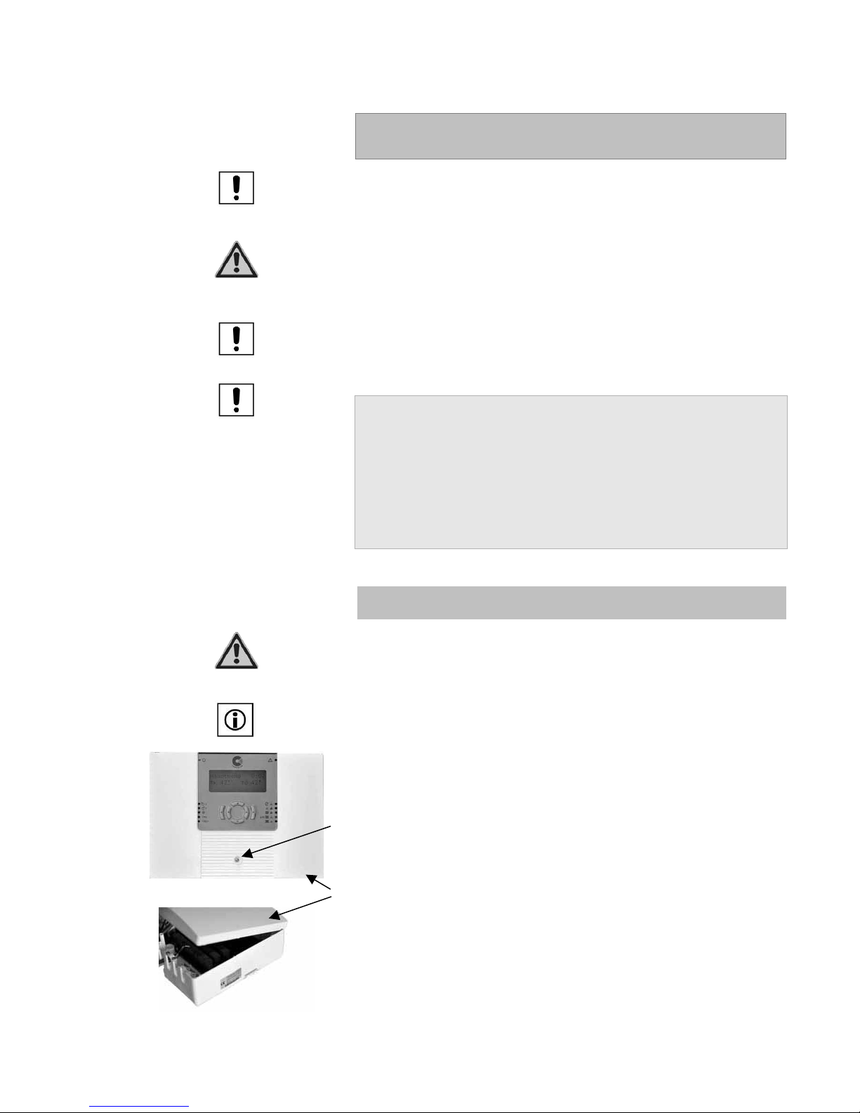
TDMA CONTROL 602-702 Eng Nov.doc
54
6 Asembly CONTROL 602
The unit must be restricted to indoor use only.
Authorised personnel must carry out all work under the relevant local and
national guidelines.
Note to VDE Guidelines
The relevant local and IEE regulations must be observed. The sensor cables
carry low voltage and should not share a trunking with cables carrying more
than 50 V.
Note on Electrical Wiring
The pin assignments of inputs and outputs occur under the controller
connection information in Section 5.13 and 5.14.
Note on the Position of the Collector Sensor
The sensor should be mounted on the last possible absorber plate
(TUBO 12), so as to be able to pick up the maximum insolation.
If a pocket is used (PLANO 27), a good contact must be made
between the sensor and the pocket. The use of heat conducting
paste is recommended. In no case should the sensor be mounted
outside of the collector.
Incorrect positioning of the sensor can lead to inaccurate
collector temperature measurement and thus the controller will
not function correctly.
6.1 Mounting the CONTROL 602
Caution
The controller should only be opened after the power has been disconnected
from it. Risk of electrical stock and death!
Note for Mounting the Controller
The template, included, should be used to mount the controller.
After removing the screw (1) the front cover can be tilted up from the front (2)
and removed (see picture opposite). When you reinsert the upper part make
sure the hinges slide into the slots provided, before lowering the front section
and refixing the screw.
2
1
Page 55
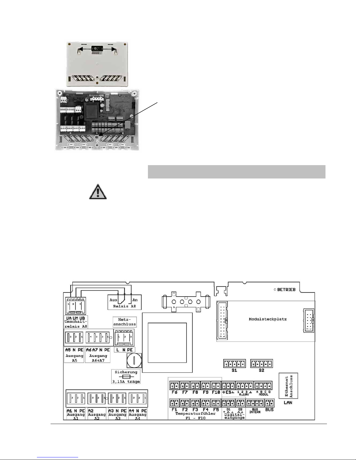
TDMA CONTROL 602-702 Eng Nov.doc
55
The lower housing section is fixed to the wall by three screws. First drill and
screw two screws into the wall at 140 mm centres. Mount housing onto these
screws and then drill and insert the third screw through the lower hole and fix
to the wall.
Third screw location hole
Thereafter, the electrical connections can be made.
6.2 Electrical Connections CONTROL 602
Caution
Never remove the front cover when mains voltage is present! Danger!
In order to prevent faulty operation during commissioning, the connections
should be made in the following order:
1. Sensor and network connections
2. Set he system variant (see Section 5.3)
3. Interrupt the power supply and connect all outputs.
Not following this sequence can lead to faluty operation during
commissioning, causing the ‘Restore Factory Settings’ to be implemented which
goes automatically to Variant A, which may not match the desired output
circuits.
6.2.1 Connection Board - CONTROL 602
140m
Page 56
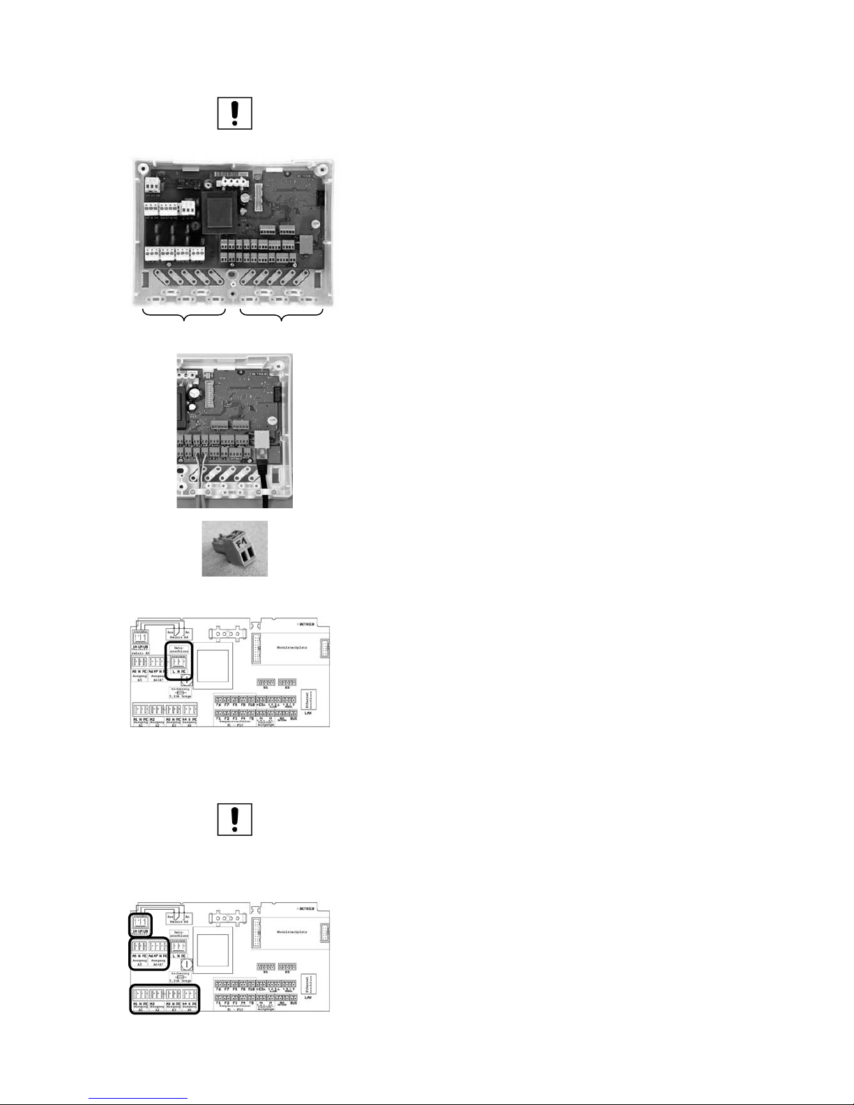
TDMA CONTROL 602-702 Eng Nov.doc
56
Note: Mains Voltage
When mains voltage is applied to the controller, a green LED ‘Power’ light
(top right hand side of the front cover) will be illuminated.
230V cables (inputs and outputs) are installed on the left hand side of the
controller, whilst the sensor cables (inputs) and network cable is to be installed
on the right.
All cables must be secured by the cable clamps and screws provided, as
shown in the photograph adjacent.
NOTE!
The connection plugs indicate whether they are inputs or outputs, thus ensuring
the appropriate connections are made correctly.
6.2.2 Electrical Connection
The CONTROL 602 is powered by an external power supply 230 V ± 10 %
(50-60 Hz). The connections are made to the terminals L/ N/ PE (see drawing
adjacent).
6.2.3 Outputs
Note:
Control relays and contactors are connected to the outputs of the CONTROL
602 and 702. These may not be `Hum-free’. A`Hum-free’ contctor can lead
to a shutdown of the controller output and is not reliable. Check the outputs
and the connected loads after startup and treat with respect. We rocmmend
the use of Consolar contactors (RE080 und RE081).
6.2.3.1 Outputs
The outputs 1...7 are respectively 230 V outputs. These outputs are connected
to terminals A1 through to A7.
Output 8 is a potential free contact. The output should be connected to the
terminals A8 (UA, UM, UB). If the output 8 is switched, contacts M-A are
closed.
230V
Sensor cables
Page 57
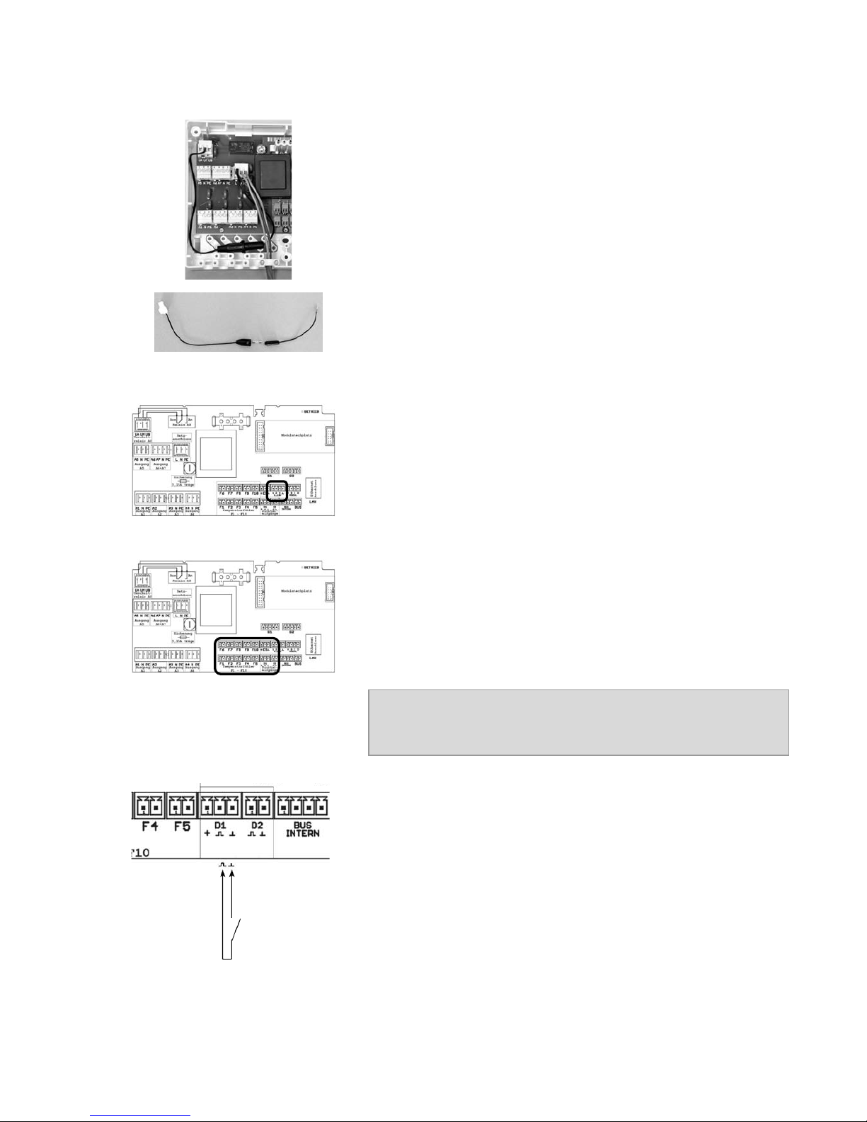
TDMA CONTROL 602-702 Eng Nov.doc
57
6.2.3.2 Potential Free Output
With the potential free output, a 230 V output can be realised by installing a
link between the Live terminal and the output terminal 8, using the link cable
provided.
6.2.3.3 0-10V Outputs
A boiler connected to a modulating signal, has to be connected to terminals 1
and GND. When using a boiler/store-charging pump with either 0-10 V or
PWM signal, use terminal 2 and GND.
The digital output A3 is not occupied.
6.2.4 Inputs
The connection of the temperature sensors goes to terminals F1 through to
F10. The polarity of the sensor connections is arbitary.
To avoid damage to the collector sensor by lightning, the installation of a
surge protector (No. RE500) is recommended.
The digital output A3 is not occupied.
Example of maximum cable length:
Sensor
Cable
Max length
PT 1000
2 X 0,75 mm
25 m
6.2.5 Connection of Comfort Button
The connection of the comfort button (for DHW and back-up heating extra
comfort or circulation) needs to be put into digital input part of D1 and Gnd.
Page 58
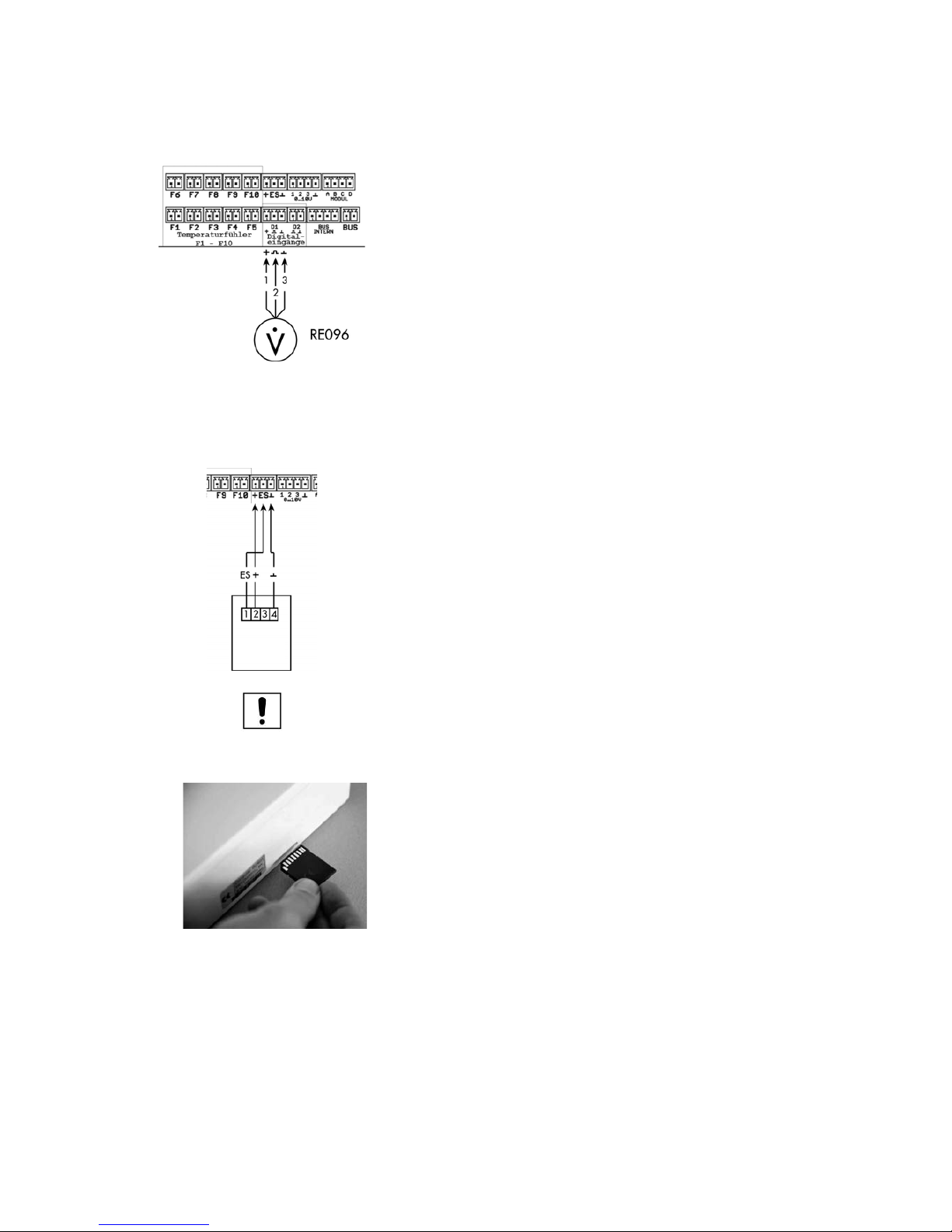
TDMA CONTROL 602-702 Eng Nov.doc
58
6.2.6 Connection of Flow Measuring Unit (RE096)
Used for Yield measurement.
A volume flow-measuring unit is connected at D2 (see figure). The
corresponding option or additional functions should be activated.
1 = White (+ 24 Volt) in D1
2 = Green (Impulse input) in D2
3 = brown (GND) in D2
6.2.7 Connecting Insolation Sensor (RE354)
For measurement purposes, n insolation sensor can be connected to the
CONTROL 602. The terminal layout is shown in the adjacent figure.
Note
The function of the insolation sensor is described in Section 5.5.1.
6.2.8 Inserting the SD Card into the CONTROL 602
The SD Card nust be inserted into the designated slot on the right hand side of
the controller with the contacts facing up-wards. In the menu setting turn the
SD card recording to On. Now the data will be recorded. In the case of a
filaure, the problem may be abled to be pinpointed based on the recorded
data saved.
RE354
Page 59
TDMA CONTROL 602-702 Eng Nov.doc
59
7 Assembly CONTROL 702
The unit must be restricted to indoor use only.
Authorised personnel must carry out all work under the relevant local and
national guidelines.
Note to VDE Guidelines
The relevant local and IEE regulations must be observed. The sensor cables
carry low voltage and should not share a trunking with cables carrying more
than 50 V.
Note on Electrical Wiring
The pin assignments of inputs and outputs occur under the controller
connection information in Section 5.13 and 5.14.
Note on the Position of the Collector Sensor
The sensor should be mounted on the last possible absorber plate
(TUBO 12), so as to be able to pick up the maximum insolation.
If a pocket is used (PLANO 27), a good contact must be made
between the sensor and the pocket. The use of heat conducting
paste is recommended. In no case should the sensor be mounted
outside of the collector.
Incorrect positioning of the sensor can lead to inaccurate
collector temperature measurement and thus the controller will
not function correctly.
7.1 Mounting the CONTROL 702
Caution
The controller should only be opened after the power has been disconnected
from it. Risk of electrical stock and death!
Note for Mounting the Controller
The template, included, should be used to mount the controller.
The controller consists of two plastic housing. As standard both housing are
assembled one on top of the other. The controller can be split to fit side by
side, which is possible with the separately available cover (RE123)
Top cover (with disply, control buttons and LED status indicators).
Page 60
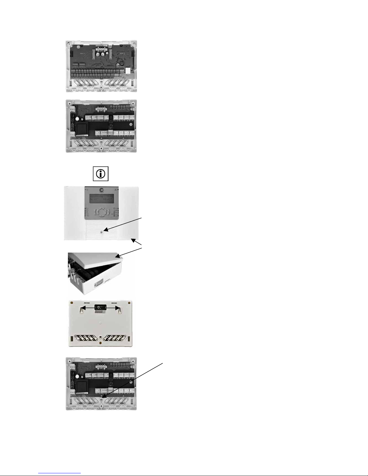
TDMA CONTROL 602-702 Eng Nov.doc
60
Input Unit (with inputs, Ethernet socket and SD slot).
Output Unit (with power supply and outputs)
7.1.1 Superimposed Assembly
Note: For mounting the controller, the output unit is always
secured under the input unit.
After removing the screw (1) the front cover can be tilted up from the front (2)
and removed (see picture opposite). When you reinsert the upper part make
sure the hinges slide into the slots provided, before lowering the front section
and refixing the screw.
The lower housing section is fixed to the wall by three screws. First drill and
screw two screws into the wall at 140 mm centres. Mount housing onto these
screws and then drill and insert the third screw through the lower hole and fix
to the wall.
Third screw location hole
Thereafter, the electrical connections can be made (see Section 7.2).
2
1
140m
Page 61
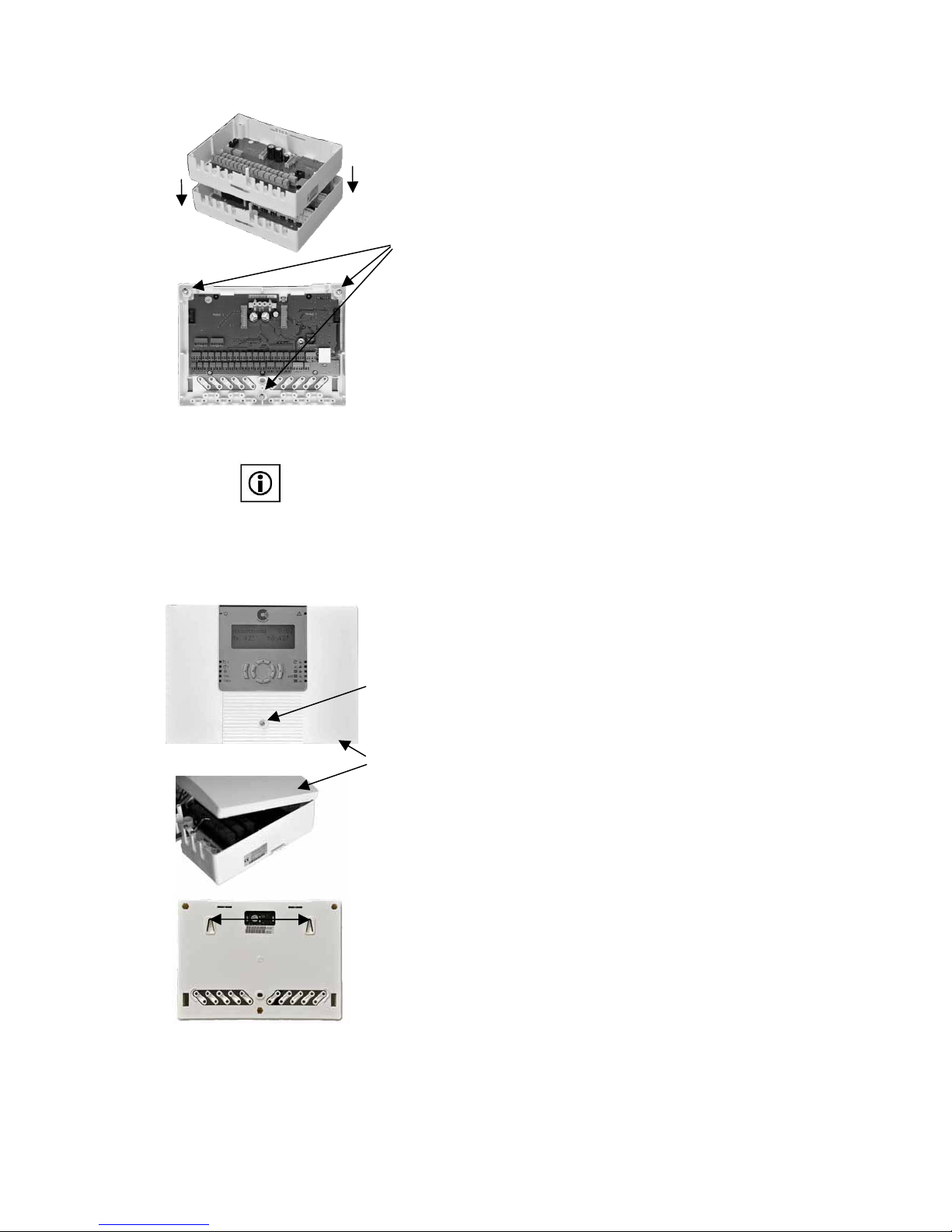
TDMA CONTROL 602-702 Eng Nov.doc
61
After completing the electrical connections of the output unit, the input unit is
placed on top of the output unit and secured with three screws.
Screws
The electrical connections of the input unit can be installed (sensors, etc.).
7.1.2 Adjacent Mounting of Controller Units
Note: To fix the controller
An adjacent assembly is only possible with the separate cover (RE123). The
input module must be installed always to the right of the output module. This is
to prevent the SD Card slot from being blocked by the output unit. RE123
includes all the necessary cables etc to connect both sections together. After
connecting both sections the output unit should be fitted with the blank cover.
After removing the screw (1) the front cover can be tilted up from the front (2)
and removed (see picture opposite). When you reinsert the upper part make
sure the hinges slide into the slots provided, before lowering the front section
and refixing the screw.
The lower housing section is fixed to the wall by three screws. First drill and
screw two screws into the wall at 140 mm centres. Mount housing onto these
screws and then drill and insert the third screw through the lower hole and fix
to the wall.
2
1
140m
Page 62
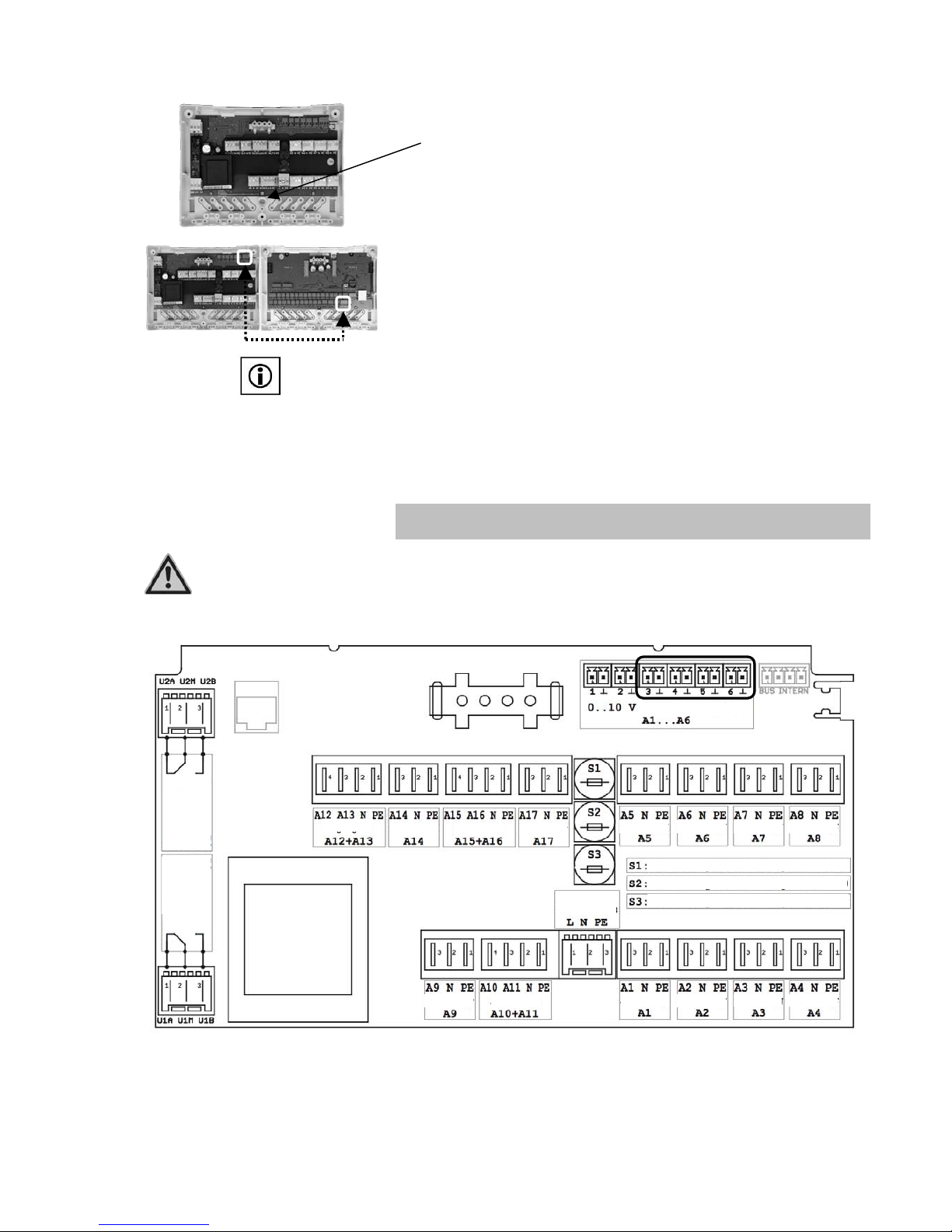
TDMA CONTROL 602-702 Eng Nov.doc
62
Third screw location hole
Install the input unit in the same way as the output unit, but on the right hand
side of the output unit. By using the enclosed bus cable, connect the input and
output units (connect to terminals marked as `Internal Bus’
Note:
The bus cable must not be extended! The cable can be cut, but remember the
order of the wires.
Make the electrical according to Section 7.2.
7.2 Electrical Connections CONTROL 702
Caution
Never remove the front cover when mains voltage is present! Danger!
7.2.1 Connector Board CONTROL 702 Output Unit
The 0…10 V Analoge Outputs A3…A6 are not used.
Ausgang
Ausgang
Ausgang
Ausgang
Ausgang
Ausgang
Ausgang
Ausgang
Ausgang
Ausgang
Ausgang
Ausgang
Ausgang
Ausgang
Netzanschluss
Sicherung 3,15A träge A1 … A4
Sicherung 3,15A träge A5 … A10
Sicherung 3,15A träge A11 … A16
Ausgang
A19
Umschaltrelais U2
Ausgang
A18
Umschaltrelais U1
AN
AN
Analog- Ausgänge
Ausgang
Page 63
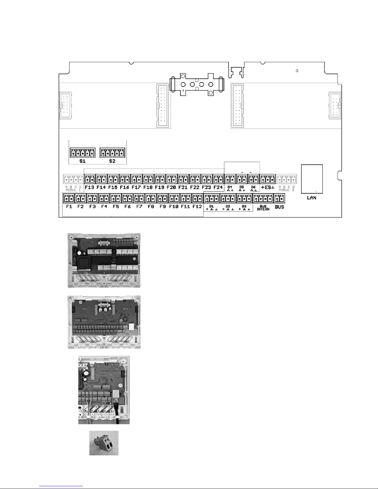
TDMA CONTROL 602-702 Eng Nov.doc
63
7.2.2 Connector Board CONTROL 702 Input Unit
230 V cables (mains supply and output cables) installed in the output unit.
Sensor cables (inputs) and network cable installed in the input unit.
All cables must be secured by the cable clamps and screws provided, as
shown in the photograph adjacent.
NOTE!
The connection plugs indicate whether they are inputs or outputs, thus ensuring
the appropriate connections are made correctly.
Modulsteckplatz 1
Modulsteckplatz 2
Temperaturfühler F1 – F24
Digitaleingänge
Ethernet-
Anschluss
Betrieb
Page 64
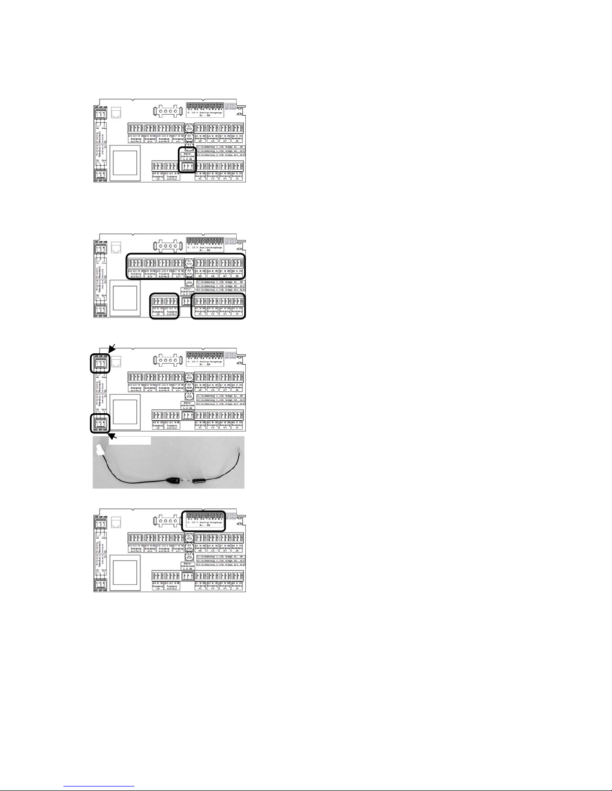
TDMA CONTROL 602-702 Eng Nov.doc
64
7.2.3 Power Supply (Output Unit)
The CONTROL 702 is powered by an external power supply 230 V ± 10 %
(50-60 Hz). The connections are made to the terminals L/ N/ PE (see drawing
adjacent).
7.2.4 Outputs (Output Unit)
7.2.4.1 230 V Output
The outputs 1 ..7 are respectively 230 V outputs. These outputs are connected
to terminals A1 through to A7.
7.2.4.2 Potential Free Output
The outputs 18 and 19 are potential free switching relays (max. 240 V, max.
2A), not protected. The output loads are connected to terminals U1 and U2.
The load of output 18 should be connected to the terminals of U1 (U1A, U1M,
U1B). If the output is switched, the contact U1M-U1A is closed.
The load of output 19 should be connected to the terminals of U2 (U2A, U2M,
U2B). If the output is switched, the contact U2M-U2A is closed.
Should either of these volt free outputs require a 230V supply, a link between
L and the appropriate UM terminals will provide the operating voltage for the
required output.
7.2.4.3 0 – 10 V Output
If a boiler requires a modulating input signal, connect to terminals 1 and GND.
If the boiler/store charge pump requires 0-10V or PWM signal, this is to be
connected into terminals 2 and GRD.
The digital outputs A3 – A6 are not used.
U2 (A19)
U1 (A18)
Page 65
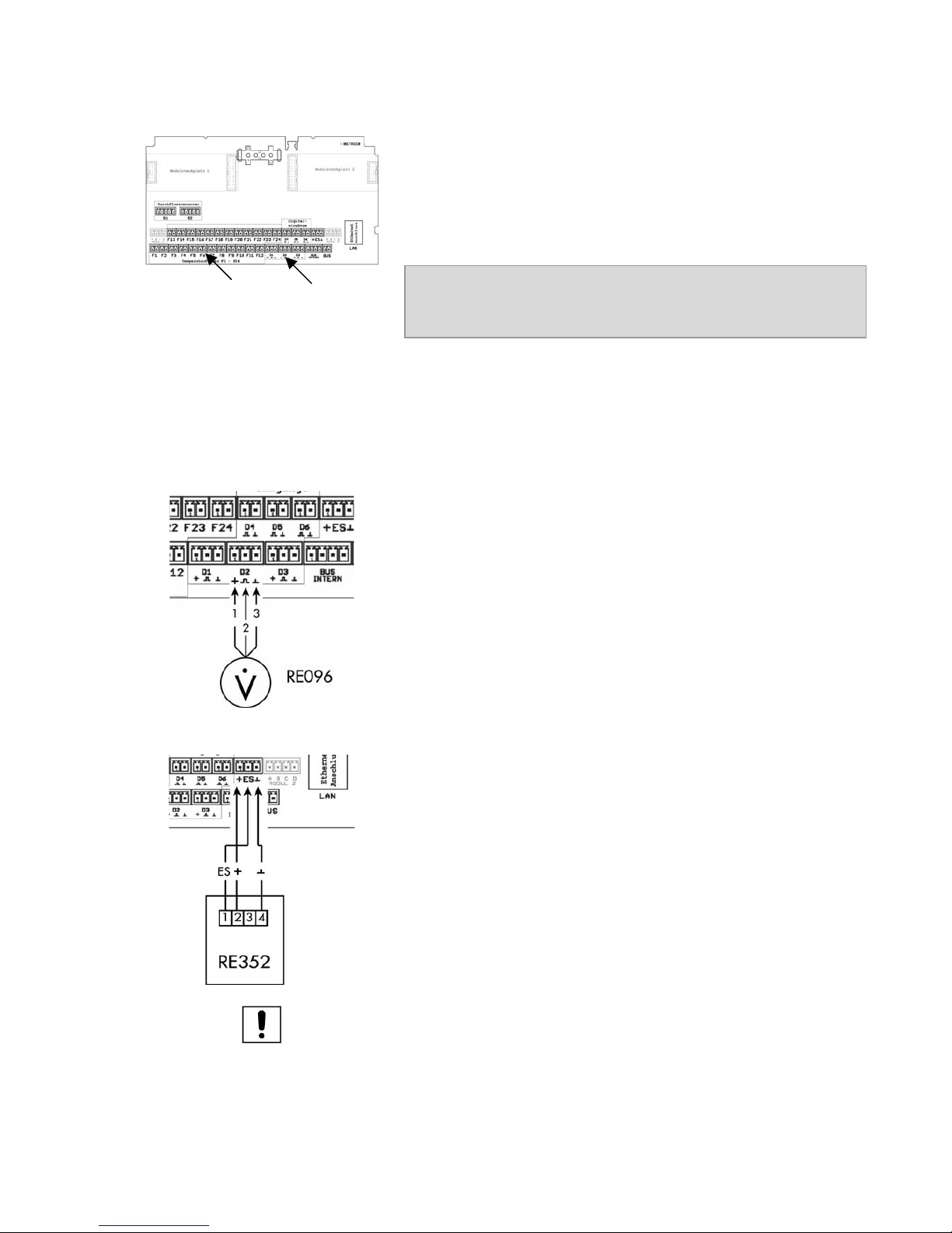
TDMA CONTROL 602-702 Eng Nov.doc
65
7.2.5 Inputs (Input Unity)
Terminals F1 to F24 are for the connection of temperature sensors. The
polarity of the sensor connections is arbitary.
To prevent damage to the collector sensor by lighting, install a surge protector
(No. RE500) is recommended.
Terminals D1 to D6 are for digital inputs.
Example of the maximum cable length:
Sensor
Cable
Length to
PT 1000
2 X 0,75 mm
25 m
7.2.5.1 Connection of the Comfort Button
See section 6.2.5 for further details
7.2.5.2 Connection of Flow Measuring Unit (RE096)
A volume flow-measuring unit if used should be connected to D2 (see diagram
opposite).
The wire assignment when using a Consolar flow-measuring unit (RE096) are
as follows:
1 = White (+ 24 Volt)
2 = Green (Impulse input)
3 = brown (GND)
7.2.5.3 Connecting Insolation Sensor (RE354)
For measurement purposes, an insolation sensor can be connected to the
CONTROL 702. The terminal layout is shown in the djacent figure.
Note:
The function of the insolation sensor is described in Section 5.5.1
7.2.6 Installing the SD Card in the CONTROL 702
See section 6.2.8 for further details
Temperaturfühler
Digitaleingäng
Page 66
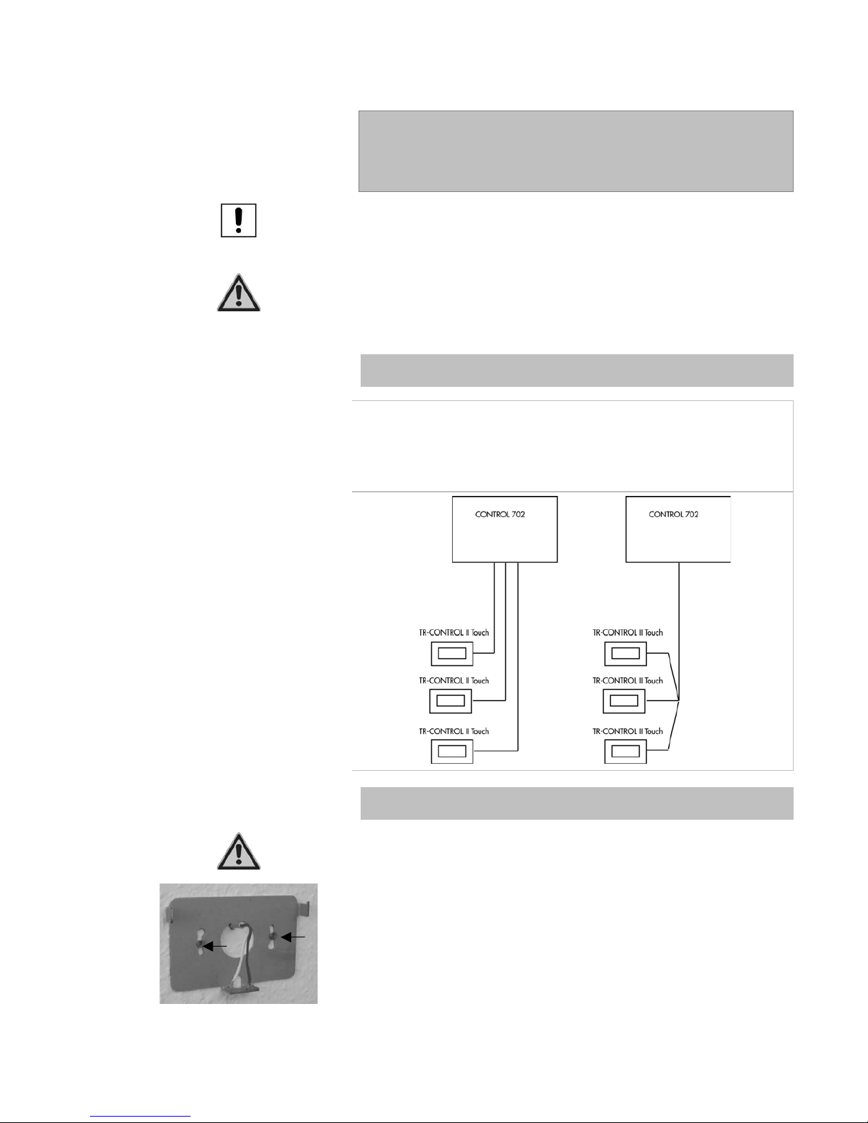
TDMA CONTROL 602-702 Eng Nov.doc
66
8 Installation and Commissioning
of the TR-CONTROL II Touch
The unit is for indoor use only.
All work must be in accordance with relevant local and national guidelines
and by authorised personnel.
Note: VDE Directive
The relevant local and IEE regulations must be observed. The sensor cables
carry low voltage and should not share the same truncking/conduit/cable tray
with cables carrying more than 50V.
8.1 Connecting the TR-CONTROL II Touch
One TR-CONTROL II Touch can be connected to a CONTROL 602, whilst the
CONTROL 702 can have 3. The wiring is via a 2-core cable, which is
provided (0.5mm2 x 30m). The cables should not be installed next to any
230V cables.
The following cabling connections are available.
8.2 Mounting the TR-CONTROL II Touch
Caution
Only open the TR-CONTROL when the power has been disconnected.
Note on fixing unit
Secure the base plate to the wall by two screws, as shown in the picture
opposite.
Page 67
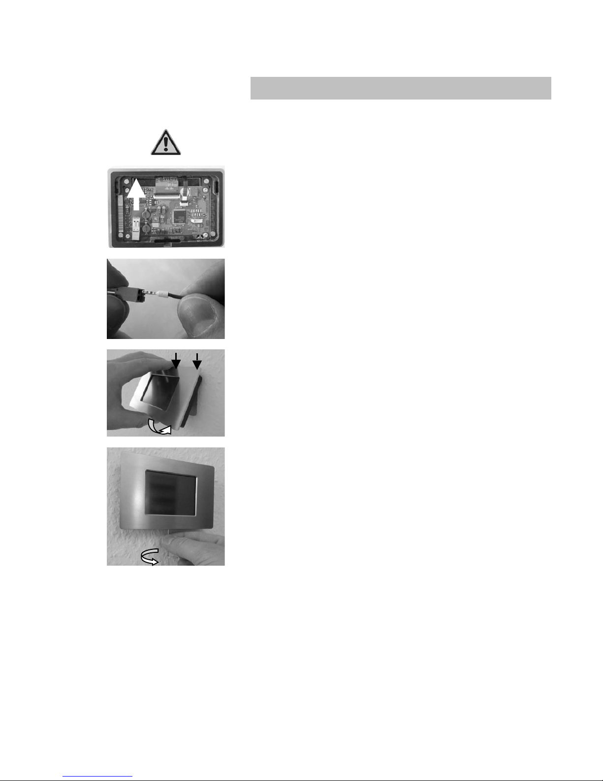
TDMA CONTROL 602-702 Eng Nov.doc
67
8.3 Electrical Connection TR-CONTROL II Touch
8.3.1 Connecting the TR-CONTROL II Touch
Caution
The unit should only be opened when the power has been disconnected.
Remove the connector for the connecting cable from the board.
Insert the connecting cable into the terminals of the connector.
Then plug the connector back into the board.
Insert the top of the front panel (1) onto the base section and swing down (2)
Use the Allen key to secure the front panel to the rear base section.
1
2
Page 68
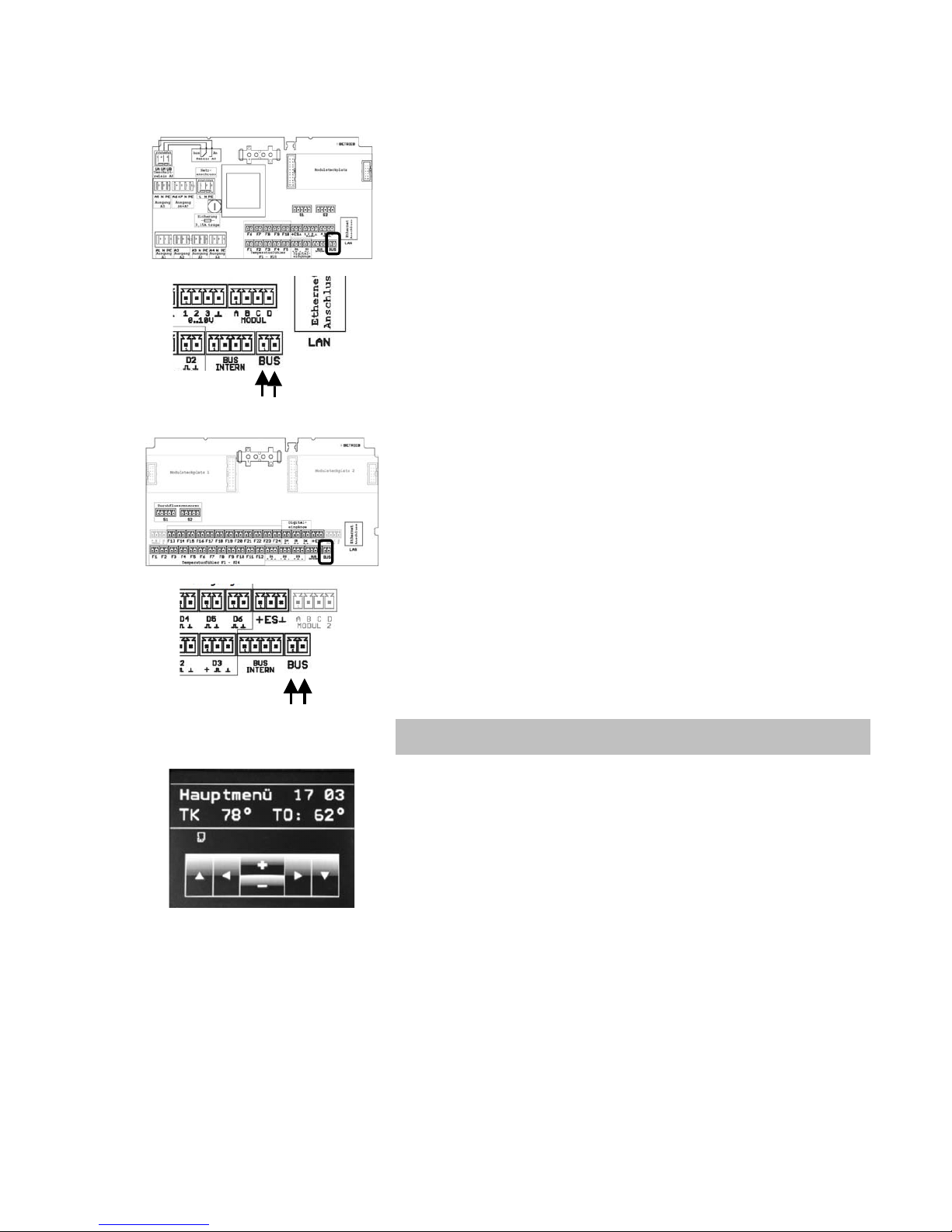
TDMA CONTROL 602-702 Eng Nov.doc
68
8.3.2 Connecting to the CONTROL 602
Connect the cabling from the TR-CONTROL II Touch into the terminals of the
CONTROL 602 marked as ‘BUS’.
The cables can be connected to either terminal, as there is no polarity to be
considered!
8.3.3 Connecting to the CONTROL 702
Connect the cabling from the TR-CONTROL II Touch into the terminals of the
Input Section of the CONTROL 702 and which is marked as ‘BUS’
The cables can be connected to either terminal, as there is no polarity to be
considered!
8.4 Start-up
The TR_CONTROL II Touch will automatically start-up on power up. After a
few seconds the display panel shows the control buttons and display. If
necessary each TR-CONTROL must be set to the appropriate heating circuit
(see section 5.7.1.1)
Page 69

TDMA CONTROL 602-702 Eng Nov.doc
69
9 Troubleshooting and Functon
Control
In the event that a temperature sensor becomes defective (short or open), the
controller will respond according to the tables set out below. Whenever a fult
occurs, the LCD display will flash with the fault and the Service Engineer’s
telephone number (if programmed).
d$7&66'57#?$%%%%
>&$8?6%%%M6\%\\\%
If a sensor is interrupted, the display shows the measure opposite.
>K?67%9#6;'#7%%
>&$8?6%%%M6\%\\\%
A sensor short circuit will appear on the display with the message opposite.
The fault messages are only programmed for functions and their outputs! If a
function (eg. Yield) is not activated and no sensor connected, no error will be
displayed. There will be no reaction to the absence of the sensor. A fault
message will be generated if the collector sensor is not installed when the
system is powered up.
9.1 Solar Control without Additional Function
Sensor Failure
Action
Collector Sensor
Solar pump = Off
Cooling = Normal operation
DHW heating = Normal operation
Store Top Sensor
Solar pump = Off
Cooling = Off
DHW Heating = Off
Store Bottom Sensor
Solar pump = Off
Cooling = Normal operation
DHW Heating = Normal operation
9.2 Solar Control with Active Frost Protection Control
Sensor Failure
Action
Collector Sensor
Solar pump = Off
Cooling = Normal operation
DHW heating = Normal operation
Store Top Sensor
Solar pump = Off
Cooling = Off
DHW Heating = Off
Store Bottom Sensor
Solar pump = Off
Cooling = Normal operation
DHW Heating = Normal operation
Page 70

TDMA CONTROL 602-702 Eng Nov.doc
70
Frost Protection Sensor
Solar pump = Normal operation and when collector
temperature <20°C, then solarpump = On. When collector
temperature > 22°C, then solar pump = off
Cooling = Normal operation
DHW Heating = Off
Frost protection sensor and collector
sensor (short circuit)
Or
Frost protection sensor, collector sensor
(short circuit) and store bottom sensor
Solar pump = On but when store top temperature is >90°C,
then solar pump = Off
Cooling = Normal operation
DHW Heating = Off
Frost protection sensor and collector
sensor (interruption)
Or
Frost protection sensor, collector sensor
(interruption) and store bottom sensor
Solar pump = Off
Cooling = Normal operation
DHW Heating = Off
Frost protection sensor and store top
sensor
Or
Frost protection sensor and cylinder
sensor below
Solar pump = Off, but when collector temperature is r <
20°C, then solar pump = On, when collector temperature is >
22°C, then solar pump = Off
Cooling = Off
DHW heating = Off
Frost protection sensor, collector sensor
and store top sensor
Solar pump = Off
Cooling = Off
DHW heating =Off
9.3 Solar Control with Two Store Control
Sensor Failure
Action
Collector Sensor
Solar pump = Off
Cooling= Normal operation
DHW Heating = Normal operation
Store Top Sensor
Solar pump = Off
Cooling = Off
DHW Heating = Off
Store Bottom Sensor
Solar pump = Off
Cooling = Normal operation
DHW Heating = Normal operation
Store Bottom Sensor 2
Solar pump = Normal operation
Cooling = Off, Uswitching to store bottom sensor
DHW Heating = Normal operation
Store bottom sensor2 and Collector
Sensor
Solar pump = Off
Cooling = Off
DHW heating = Normal operation
Store Bottom Sensor 2 and Store
Sensor Top
Solar pump = Off
Cooling = Off
DHW Heating = Off
Store Bottom Sensor 2 and Store
Bottom Sensor
Solar pump = Off
Cooling = Off
DHW heating = Normal operation
Page 71

TDMA CONTROL 602-702 Eng Nov.doc
71
9.4 Solar Control with Heating Function
Sensor Failure
Action
Collector Sensor
Solar pump = Off
Cooling = Normal operation
DHW heating = Normal operation
Store Top Sensor
Solar pump = Off
Cooling = Off
DHW heating = Off
Boiler = Off
Boiler pump = Off
Store Bottom Sensor
Solar pump = Off
Cooling = Normal operation
DHW heating = Normal operation
Store Sensor
(Return Temperature Raising)
Solar pump = Normal operation
Cooling = Normal operation
DHW heating = Normal operation
Mixing Valve = energised (AB-B)
Return Flow Sensor
(Return Temperature Raising)
Solar pump = Normal operation
Cooling = Normal operation
DHW heating = Normal operation
Mixing Valve = energised (AB-B)
Solid Fuel Boiler Sensor
(Solid Fuel Boiler)
Solar pump = Normal operation
Cooling = Normal operation
DHW heating = Normal operation
Solid Fuel Boiler pump = On
Store Sensor
(Solid Fuel Boiler)
Solar pump = Normal operation
Cooling = Normal operation
DHW heating = Normal operation
Solid Fuel Boiler pump = Pump is controlled by solid fuel boiler
sensor
Buffer Sensor
Uppe & Lower
Solar pump = Normal operation
Cooling = Normal operation
DHW heating = Normal operation
Heating pump = Normal operation
Boiler = Off (even with DHW heating on)
Boiler pump = Off
Boiler Sensor
Solar pump = Normal operation
Cooling = Normal operation
DHW heating = Off
Heating pump = Normal operation
Boiler = Off
Boiler pump = Off
External Air Temperature Sensor
Solar pump = Normal operation
Cooling = Normal operation
DHW heating = Normal operation
Heating pump = Off
Boiler = Off
Heating Circuit Flow Sensor
Solar pump = Normal operation
Cooling = Normal operation
DHW heating = Normal operation
Heating pump = Off
Boiler = Normal operation
Page 72
TDMA CONTROL 602-702 Eng Nov.doc
72
NOTE:
The statements made in the technical
documentation and the information
provided, do not lay claim to
completeness and do not replace
professional planning. Changes and
errors excepted.
Technischer
Support:
07621-42228-504
Consolar Product and advice from:
Consolar Solare
Energiesysteme GmbH
Gewerbestraße 7
D - 79539 Lörrach
Fon: 07621-42228-500
Fax: 07621-42228-31
[email protected]
www.consolar.com
Stand 27.04.2012
Änderungen und Irrtum vorbehalten.
NOTIZEN
………………………………………………………………………………………………………………………………………
…………………………………
………………………………………………………………………………………………………………………………………
………………………………………………………………………………………………………………………………………
………………………………………………………………………………………………………………………………………
………………………………………………………………………………………………………………………………………
………………………………………………………………………………………………………………………………………
………………………………………………………………………………………………………………………………………
………………………………………………………………………………………………………………………………………
………………………………………………………………………………………………………………………………………
………………………………………………………………………………………………………………………………………
………………………………………………………………………………………………………………………………………
………………………………………………………………………………………………………………………………………
………………………………………………………………………………………………………………………………………
………………………………………………………………………………………………………………………………………
……………………………………………………………………………………………………………
Consolar UK
Greenshop Solar Ltd
Calf Way
Bisley
Gloucestershire
GL6 7BX
01452 772030
[email protected]
 Loading...