

Page 1

304202P003
Rev. C
October 2008
SRT X-BAND TRANSCEIVER
RADAR SYSTEMS
TECHNICAL MANUAL
CONSILIUM SELESMAR s.r.l.
Head Office & Plant
Via Romita, 26 - 50020 Montagnana V. P. (Florence) Italy
Tel.: +39/0571/68121 Telefax +39/0571/670798
www.consilium.se
Page 2

REV. C
304202P003
October 2008
SRT X-BAND
MANUAL
TRANSCEIVER
RADAR SYSTEMS
TECHNICAL
Page 3

SRT X-BAND RADAR SYSTEMS
FOREWORD
APPLICATION FOR MANUAL REVISIONS
Upon receipt of this manual, please fill in the necessary data. It is important that the addressee be the end user so that the operating personnel
will receive all revisions to the manual
EQUIPMENT NAME .............................................................................................
SERIAL No...................................... MODEL ......................................................
MANUAL TITLE ....................................................................................................
........................................................ MANUAL PART NUMBER.........................
ISSUED INDEX............................... REVISION INDEX......................................
PURCHASING AGENCY......................................................................................
NAME OF USER...................................................................................................
ADDRESS OF USER............................................................................................
.............................................................................................................
.............................................................................................................
ATTN:...................................................................................................
304202P003 A Rev. C
Page 4

SRT X-BAND RADAR SYSTEMS
FOREWORD
RECORD OF CHANGES
RCS CODE/REV. INDEX DATE
Revision A NOV 2007 First Emission
Revision B April 2008
Revision C
October
2008
PURPOSE OF
THE CHANGE
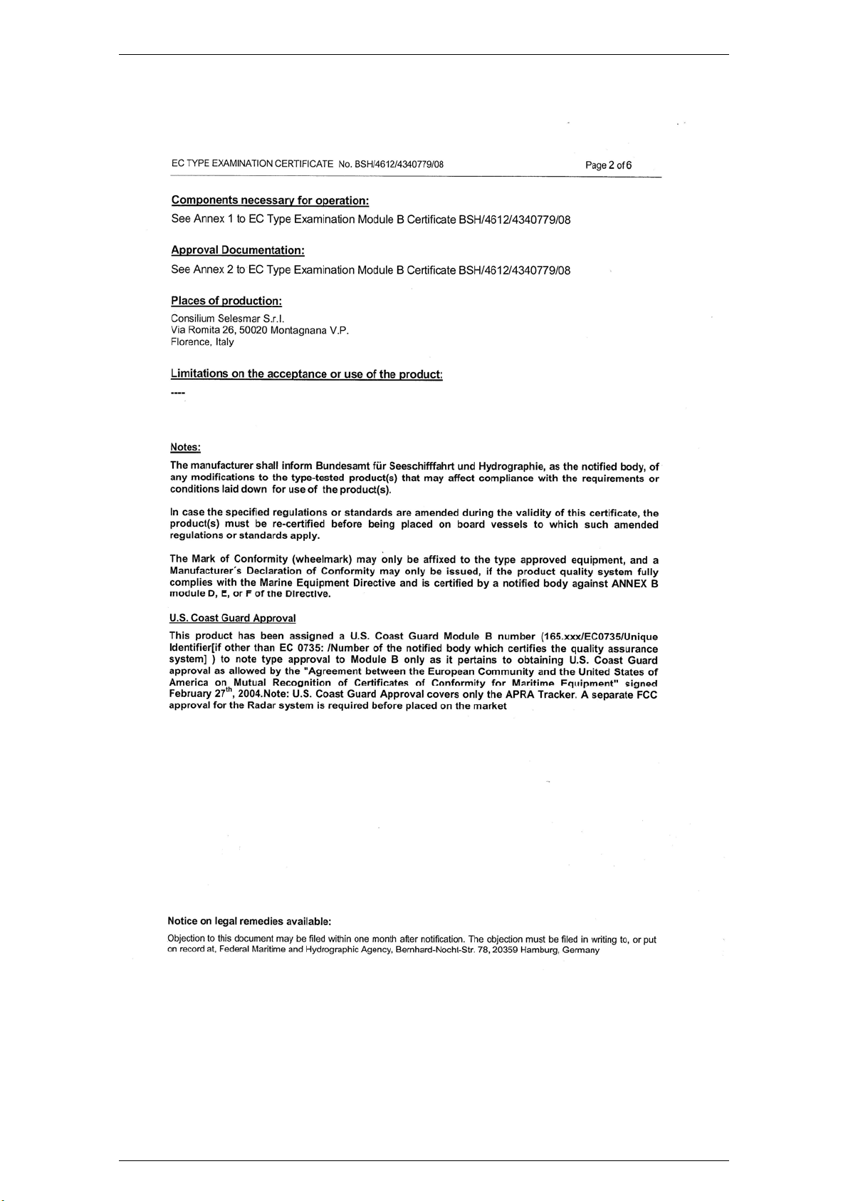
Add the EC
CERTIFICATE
Replace the EC
CERTIFICATE
CHANGE
REQUESTED BY
Request for Changes
014/08
Request for Changes
044/08
304202P003 B Rev. C
Page 5

SRT X-BAND RADAR SYSTEMS
FOREWORD
304202P003 C Rev. C
Page 6
SRT X-BAND RADAR SYSTEMS
FOREWORD
304202P003 D Rev. C
Page 7
SRT X-BAND RADAR SYSTEMS
FOREWORD
304202P003 E Rev. C
Page 8
SRT X-BAND RADAR SYSTEMS
FOREWORD
304202P003 F Rev. C
Page 9
SRT X-BAND RADAR SYSTEMS
FOREWORD
304202P003 G Rev. C
Page 10

SRT X-BAND RADAR SYSTEMS
FOREWORD
304202P003 H Rev. C
Page 11
SRT X-BAND RADAR SYSTEMS
FOREWORD
304202P003 I Rev. C
Page 12

SRT X-BAND RADAR SYSTEMS
FOREWORD
304202P003 J Rev. C
Page 13
SRT X-BAND RADAR SYSTEMS
FOREWORD
304202P003 K Rev. C
Page 14

SRT X-BAND RADAR SYSTEMS
FOREWORD
304202P003 L Rev. C
Page 15

SRT X-BAND RADAR SYSTEMS
FOREWORD
MANUAL TABLE OF CONTENTS
Warnings
Chapter 1 DESCRIPTION AND MAIN CHARACTERISTICS
Chapter 2 OPERATION
Chapter 3 FUNCTIONAL DESCRIPTION
Chapter 4 PREVENTIVE MAINTENANCE
Chapter 5 TROUBLESHOOTING
Chapter 6 CORRECTIVE MAINTENANCE
Chapter 7 PART LIST
Chapter 8 INSTALLATION
Chapter 9 FIGURES
304202P003 M Rev. C
Page 16

SRT X-BAND RADAR SYSTEMS
INDEX
TABLE OF CONTENTS
CHAPTER 1 DESCRIPTION AND MAIN CHARACTERISTICS..................................................1.1
1.1 INTRODUCTION........................................................................................................................1.1
1.1.1 MANUAL APPLICABILITY ........................................................................................................1.1
1.1.2 THE PURPOSE OF THE EQUIPMENT............................................................................................1.2
1.1.3 LIST OF ABBREVIATIONS.........................................................................................................1.3
1.2 CONFIGURATION TABLE..........................................................................................................1.4
1.3 PHYSICAL DESCRIPTION..........................................................................................................1.5
1.3.1 ANTENNA................................................................................................................................1.6
1.3.2 PEDESTAL ...............................................................................................................................1.7
1.3.2.1 MAIN CONNECTOR .............................................................................................................1.7
1.3.2.2 SRT ELECTRONICS PARTS ..................................................................................................1.8
1.3.2.3 MOTOR UNIT......................................................................................................................1.9
1.3.2.4 PEDESTAL FOR DOWNMAST CONFIGURATION ..................................................................1.10
1.4 FUNCTIONAL DESCRIPTION ...................................................................................................1.11
1.5 TECHNICAL CHARACTERISTICS .............................................................................................1.12
CHAPTER 2 OPERATION...................................................................................................................2.1
2.1 INTRODUCTION........................................................................................................................2.1
2.1.1 PURPOSE .................................................................................................................................2.1
2.2 CONTROLS AND INDICATORS...................................................................................................2.1
2.3 SEMI-OPERATIVE CONTROLS...................................................................................................2.1
2.4 NMEA TRANSFER PROTOCOL.................................................................................................2.3
2.4.1 ABBREVIATIONS......................................................................................................................2.3
2.4.2 DATA TRANSMISSION FROM RDC TO TXRX (OR INTERFACES)..............................2.4
2.4.2.1 OPERATIONAL CONTROL SENTENCE 2....................................................................2.4
2.4.2.2 SECTOR BLANKING SENTENCE.................................................................................2.4
2.4.2.3 TIMERS INITIALIZATION.............................................................................................2.5
2.4.2.4 DIGITAL POTENTIOMETERS.......................................................................................2.5
2.4.3 DATA TRANSMISSION FROM TXRX TO RDC................................................................2.6
2.4.3.1 STATUS SENTENCE 2....................................................................................................2.6
2.4.3.2 DATA SENTENCE...........................................................................................................2.6
2.4.3.3 TIMERS INFORMATION................................................................................................2.7
2.4.3.4 DIGITAL POT. INFORMATION....................................................................................2.7
2.4.3.5 SECTOR BLANKING SENTENCE.................................................................................2.8
2.4.3.6 WRONG COMMAND RETURN (NACK) ...................................................................... 2.8
2.4.3.7 HEALTH SENTENCE 2...................................................................................................2.8
2.4.3.8 DATA SENTENCE 3........................................................................................................2.9
2.4.4 GENERAL NOTES..............................................................................................................2.10
CHAPTER 3 FUNCTIONAL DESCRIPTION....................................................................................3.1
3.1 INTRODUCTION........................................................................................................................3.1
3.2 FUNCTIONAL DESCRIPTION .....................................................................................................3.2
3.2.1 ELECTRONICS RACK................................................................................................................3.2
3.2.1.1 SRT POWER BOARD...........................................................................................................3.3
3.2.1.2 SRT POWER - LOW VOLTAGE POWER SUPPLY ...................................................................3.3
3.2.1.3 SRT_POWER - HIGH VOLTAGE POWER SUPPLY .................................................................3.3
3.2.1.4 SRT_MOS BOARD..............................................................................................................3.4
3.2.1.5 SRT_CONTROL BOARD......................................................................................................3.5
3.2.1.6 MICROPROCESSOR AND GATE ARRAY ................................................................................3.6
3.2.1.6.1 GENERAL DESCRIPTION......................................................................................................3.6
3.2.1.6.2 FUNCTIONS PERFORMED ....................................................................................................3.7
3.2.1.6.3 MICROPROCESSOR OUTPUT SIGNALS .................................................................................3.7
3.2.1.6.4 MICROPROCESSOR INPUT SIGNALS.....................................................................................3.7
3.2.1.6.5 GATE ARRAY INPUT SIGNAL ..............................................................................................3.8
3.2.1.6.6 GATE ARRAY OUTPUT SIGNAL...........................................................................................3.9
3.2.1.6.7 GATE ARRAY PULSE LENGTH GENERATOR ........................................................................3.9
304202P003 i Rev. C
Page 17

SRT X-BAND RADAR SYSTEMS
INDEX
3.2.1.7 SYSTEM MONITOR FUNCTIONS.........................................................................................3.10
3.2.1.8 PERFORMANCE MONITOR FUNCTIONS..............................................................................3.10
3.2.1.9 INPUT AND OUTPUT INTERFACE........................................................................................3.11
3.2.1.10 AZIMUTH (AZ) AND HEADING LINE (HL) SIGNAL CIRCUIT GENERATOR.........................3.11
3.2.2 RF HEAD.............................................................................................................................3.11
3.2.3 BRUSHLESS MOTOR CONTROLLER........................................................................................3.12
3.2.4 MOTOR UNIT.........................................................................................................................3.13
3.2.5 OPTIONAL EQUIPMENT: SRT ADAPTER BOX.........................................................................3.14
3.2.6 OPTIONAL EQUIPMENT: HEATERS ........................................................................................3.14
3.2.7 OPTIONAL EQUIPMENT: ENCODER........................................................................................3.14
CHAPTER 4 PREVENTIVE MAINTENANCE..................................................................................4.1
4.1 INTRODUCTION........................................................................................................................4.1
4.2 PREVENTIVE MAINTENANCE PROCEDURE...............................................................................4.1
CHAPTER 5 TROUBLESHOOTING..................................................................................................5.1
5.1 INTRODUCTION........................................................................................................................5.1
5.1.1 GENERAL ................................................................................................................................5.1
5.1.2 ORGANIZATION.......................................................................................................................5.1
5.1.3 PERSONNEL.............................................................................................................................5.1
5.1.4 TOOLS AND INSTRUMENTS ......................................................................................................5.1
5.2 TROUBLESHHOTING PROCEDURES...........................................................................................5.2
5.2.1 SAFETY PRECAUTIONS ............................................................................................................5.2
5.2.2 TROUBLESHOOTING OPERATIONS ...........................................................................................5.2
CHAPTER 6 CORRECTIVE MAINTENANCE.................................................................................6.1
6.1 GENERAL ................................................................................................................................6.1
6.1.1 INTRODUCTION........................................................................................................................6.1
6.1.2 SAFETY PRECAUTIONS ............................................................................................................6.1
6.1.3 PERSONNEL.............................................................................................................................6.1
6.1.4 REQUIRED TOOLS AND INSTRUMENTS.....................................................................................6.1
6.2 CORRECTIVE MAINTENANCE PROCEDURES.............................................................................6.2
6.2.1 GENERAL ................................................................................................................................6.2
6.2.2 ANTENNA REPLACEMENT .......................................................................................................6.2
6.2.3 OPENING/CLOSING OF THE TXRX COVER ..............................................................................6.3
6.2.4 REPLACEMENT OF THE MOTOREDUCER ASSY .........................................................................6.3
6.2.5 REPLACEMENT OF THE BRUSHLESS MOTOR CONTROLLER......................................................6.4
6.2.6 REPLACEMENT OF THE MAGNETRON.......................................................................................6.4
6.2.7 REPLACEMENT OF THE RF FRONT END ASSY..........................................................................6.5
6.2.8 REMOVAL/INSTALLATION OF THE ELECTRONICS ASSY ...........................................................6.6
6.2.9 REPLACEMENT OF THE BEARING READER BOARD...................................................................6.7
CHAPTER 7 PART LIST ......................................................................................................................7.1
7.1 INTRODUCTION........................................................................................................................7.1
7.1.1 PART LIST ...............................................................................................................................7.1
7.1.2 PART LOCATION ILLUSTRATION..............................................................................................7.1
7.2 PART LIST TABLES..................................................................................................................7.2
CHAPTER 8 INSTALLATION.............................................................................................................8.1
8.1 INTRODUCTION........................................................................................................................8.2
8.1.1 SHIPPING.................................................................................................................................8.2
8.1.2 UNPACKING ............................................................................................................................8.2
8.1.3 STORAGE.................................................................................................................................8.3
8.1.4 HANDLING ..............................................................................................................................8.3
8.2 SPECIFICATIONS ......................................................................................................................8.3
8.2.1 DIMENSIONS AND WEIGHTS (ALSO SEE OUTLINE DRAWINGS) ................................................8.3
8.2.2 REQUIRED POWER ...................................................................................................................8.4
8.2.3 ENVIRONMENTAL DATA..........................................................................................................8.4
8.3 INSTALLATION ........................................................................................................................8.5
8.3.1 INSTALLATION PRINCIPLES .....................................................................................................8.5
8.3.2 MECHANICAL INSTALLATION ..................................................................................................8.7
8.3.2.1 UNIT (PEDESTAL + TRANSCEIVER)......................................................................................8.7
304202P003 ii Rev. C
Page 18

SRT X-BAND RADAR SYSTEMS
INDEX
8.3.2.2 ANTENNA...........................................................................................................................8.8
8.3.2.3 SAFETY SWITCH (EXTERNAL IS OPTIONAL) ........................................................................8.8
8.3.2.4 PERFORMANCE MONITOR ARM ..........................................................................................8.8
8.3.3 ELECTRICAL INSTALLATION....................................................................................................8.9
8.3.3.1 MULTICORE CABLE............................................................................................................8.9
8.3.3.2 SAFETY SWITCH .................................................................................................................8.9
8.3.3.3 GROUNDING .......................................................................................................................8.9
8.3.4 PRE SETUP PROCEDURES.......................................................................................................8.10
8.3.4.1 SHIP POWER VOLTAGE .....................................................................................................8.10
8.3.4.2 COMPASS SAFE DISTANCE................................................................................................8.11
8.4 INSTALLATION FIGURES AND DRAWINGS ..............................................................................8.12
8.5 ANNEX..................................................................................................................................8.23
8.5.1 MULTICORE CABLING AND TERMINATION PRINCIPLE...........................................................8.23
CHAPTER 9 FIGURES..........................................................................................................................9.1
FIGURE 9.1.1 SRT UP MAST GENERAL VIEW .................................................................................9.3
FIGURE 9.1.2 SRT UP MAST– EXTERNAL VIEW..............................................................................9.4
FIGURE 9.1.3 PEDESTAL EXTERNAL VIEW......................................................................................9.5
FIGURE 9.1.4 PEDESTAL INTERNAL VIEW.......................................................................................9.6
FIGURE 9.1.5 MOTOREDUCER ASSY................................................................................................9.7
FIGURE 9.1.6 ELECTRONICS RACK .................................................................................................9.8
FIGURE 9.1.7 SRT FUNCTIONAL BLOCK DIAGRAM FOR 6’ ANTENNA ............................................9.9
FIGURE 9.1.8 SRT INTERNAL CONNECTION .................................................................................9.10
FIGURE 9.1.9 SRT INTERNAL VOLTAGE AND SIGNALS..................................................................9.11
FIGURE 9.1.10 SRT_POWER - BOARD..........................................................................................9.12
FIGURE 9.1.11 SRT_POWER – GENERAL BLOCK ............................................................................9.13
FIGURE 9.1.12 SRT_POWER – PROTECTION CIRCUITS ................................................................. 9.14
FIGURE 9.1.13 SRT_POWER – LVPS CIRCUITS............................................................................9.15
FIGURE 9.1.14 SRT_POWER – HVPS CIRCUITS ...........................................................................9.16
FIGURE 9.1.15 SRT_MOS – BOARD ..............................................................................................9.17
FIGURE 9.1.16 SRT_MOS – BLOCK DIAGRAM...............................................................................9.18
FIGURE 9.1.17 SRT_CONTROL BOARD.......................................................................................9.19
FIGURE 9.1.18 SRT_CONTROL – BLOCKS...................................................................................9.20
FIGURE 9.1.19 SRT_CONTROL – MICROPROCESSOR AND GATE ARRAY.....................................9.21
FIGURE 9.1.20 SRT_CONTROL – INPUT INTERFACE ....................................................................9.22
FIGURE 9.1.21 SRT_CONTROL – OUTPUT INTERFACE.................................................................9.23
FIGURE 9.1.22 SRT_CONTROL – MONITOR ................................................................................9.24
FIGURE 9.1.23 SRT RF HEAD – FUNCTIONAL BLOCK DIAGRAM ...................................................9.25
FIGURE 9.1.24 SRT RF HEAD – L.N.F.E. .....................................................................................9.26
FIGURE 9.1.25 SRT RF HEAD – RF DETECTOR ............................................................................9.27
FIGURE 9.1.26 BRUSHLESS CONTROLLER – FUNCTIONAL BLOCKS ........................................9.28
FIGURE 9.1.27 ELECTRONICS RACK – PARTICULAR OF THE RF HEAD............................................9.29
FIGURE 9.1.28 RF AMPLIFIER ........................................................................................................9.30
FIGURE 9.1.29 ELECTRONICS RACK................................................................................................9.31
FIGURE 9.1.30 BEARING READER BOARD .......................................................................................9.32
FIGURE 9.1.31 ROTARY JOINT ........................................................................................................9.33
FIGURE 9.1.32 BRUSHLESS MOTOR CONTROLLER..........................................................................9.34
FIGURE 9.1.33 SRT DOWNMAST PEDESTAL DIMENSIONS DRAWING...............................................9.35
FIGURE 9.1.34 SRT DOWNMAST CONFIGURATION MECHANICAL ASSEMBLY ....................................9.36
FIGURE 9.1.35 SRT DOWNMAST CONFIGURATION MECHANICAL ASSEMBLY ....................................9.37
304202P003 iii Rev. C
Page 19

SRT X-BAND RADAR SYSTEMS
INDEX
LIST OF TABLES
TABLE 1.1.1 - LIST OF ABBREVIATIONS .................................................................................................1.3
TABLE 1.3.1- EQUIPMENT, ACCESSORIES AND DOCUMENTS SUPPLIED .................................................1.5
TABLE 1.3.2 – SRT X-BAND 12 AND 25KW COMPOSITION ..................................................................1.8
TABLE 1.3.3 - RF HEAD....................................................................................................................... 1.8
TABLE 1.3.4 - ELECTRONICS RACK........................................................................................................1.8
TABLE 2.3.1 - SEMI-OPERATIVE CONTROLS LOCATION OF TXRX CABINET .........................................2.1
TABLE 2.3.2 - SEMI-OPERATIVE CONTROLS LOCATION OF ELECTRONIC RACK.....................................2.2
TABLE 2.3.3 - SEMI-OPERATIVE CONTROLS LOCATION OF BRUSHLESS MOTOR CONTROLLER .............2.2
TABLE 4.2.1 - LIST OF RECOMMENDED TOOLS AND INSTRUMENTS .......................................................4.2
TABLE 4.2.2 - LIST OF THE PREVENTIVE MAINTENANCE CARDS ...........................................................4.2
TABLE 5.1.1- LIST OF RECOMMENDED INSTRUMENTS...........................................................................5.1
TABLE 5.2.1 - LIST OF MAIN POSSIBLE FAILURES)................................................................................5.1
TABLE 6.2.1 - LIST OF CORRECTIVE MAINTENANCE PROCEDURES........................................................6.2
TABLE 6.2.2 - CONNECTORS OF THE ELECTRONICS RACK .....................................................................6.7
TABLE 7.2.1- LIST OF ITEMS OF CHAPTER 9 .........................................................................................7.2
304202P003 i Rev. C
Page 20
SRT X-BAND RADAR SYSTEMS
WARNINGS
WARNINGS
IMPORTANT NOTE
For correct operation, please, read this instruction manual
carefully, before operating the equipment.
HIGH VOLTAGE
Radar equipment requires the use of high voltages. This can cause injury, or
loss of life. Danger exists only when the units are opened, exposing internal
circuits, as when servicing the equipment. You do not face any danger during
normal operation. The SRT X-Band Radar System has been carefully designed
to protect personnel from possible injury from high voltages at normal operation.
When inspecting or servicing the equipment, nevertheless, it is recommended
that the Line Switch to left open, as an added protection.
Although every effort has been made to eliminate danger to personnel, no
responsibility is accepted for any injury or loss of life suffered in connection with
the equipment.
RADIO-FREQUENCY RADIATION
Harmful effects (particularly to the eyes) may be caused by exposure of any
part of the human body to radio-frequency mean power densities. Hazard
distances at which power densities of 100 W/ m², 50 W/ m² and 10 W/m² exist,
are given in the following table
Configuration Distance to 100 W/
m² point [m]
12 kW Transceiver + 6'X Band
Antenna (ANT6X-001)
12 kW Transceiver + 9'X Band
Antenna (ANT9X-001)
12 kW Transceiver + 12'X Band
Antenna (ANT12X-001)
25 kW Transceiver + 6'X Band
Antenna (ANT6X-001)
25 kW Transceiver + 9'X Band
Antenna (ANT9X-001)
25 kW Transceiver + 12'X Band
Antenna (ANT12X-001)
Note :
12 KW transceiver: SRT/12-002 - SRT/12-003.
25 KW transceiver: SRT/25-002 - SRT/25-003 or SRT/PED-001 / SRT/PED-002 with 25KW Dowmast transceiver,
- 0,15 0,6
- - 0,5
- - 0,35
0,1 0,2 1,3
- 0,1 1,0
- 0,05 0,9
Distance to 50 W/
m² point [m]
Distance to 10 W/ m²
point [m]
The system is however designed too always disable the microwave radiation
when the antenna is not rotating.
304202P003 1 Rev. C
Page 21

SRT X-BAND RADAR SYSTEMS
WARNINGS
The pedestals have also been prepared for the installation of an external safety
switch, which can be mounted on, or near the platform. This switch removes the
power from the Pedestal eliminating the possibility of accidental operation
during servicing and also causes disabling of transmission.
Whenever it is necessary to disconnect the waveguide system from a radar
transmitter for maintenance purpose, the transmitter output should be
terminated in a matched load, when possible. If this is not possible, care should
be taken to avoid standing in front of an open-ended waveguide from which
power is being radiated.
NEVER look down a waveguide from which power is being radiated.
X-RAY RADIATION
This unit does not generate X-RAY radiation.
SAFETY SWITCH
The Radar Unit is provided with a safety switch, which disable the Antenna
movement during maintenance operations and avoids high voltage damage.
Always turn the safety switch off, whenever advised in this manual (for instance,
before performing any maintenance or installation procedure.). Ignoring safety
switch operation may produce hazard of electrocution as well as other severe
injures.
SAFETY PRECAUTIONS
Purpose
Safety precautions described in this paragraph are applicable to the SRT XBand Radar System. Depending upon the type of advice, the following attention
sings are used in the technical manual:
IF THIS OPERATING PROCEDURE, MAINTENANCE
PROCEDURE, PRACTICE, CONDITION OR STATEMENT IS
NOT STRICTLY FOLLOWED, COULD RESULT IN SEVERE
INJURY OR DEATH OF PERSONNEL
DANGER
WARNING
IF THIS IS OPERATING PROCEDURE, MAINTENANCE
PROCEDURE, PRACTICE, CONDITION OR STATEMENT IS
NOT STRICTLY FOLLOWED, COULD RESULT IN DAMAGE,
OR DESTRUCTION OF UNIT, OR LOSS OF EMISSION
EFFECTIVENESS.
304202P003 2 Rev. C
Page 22

SRT X-BAND RADAR SYSTEMS
WARNINGS
CAUTION
IF THIS IS OPERATING PROCEDURE, MAINTENANCE
PROCEDURE, PRACTICE, CONDITION OR STATEMENT IS
NOT STRICTLY FOLLOWED, COULD RESULT IN INJURY OF
PERSONNEL OR PROPERTY DAMAGE .
NOTE
Advice of an essential operating procedure, maintenance
procedure, condition or statement which must be followed.
Whenever a precaution, relating specific part of the technical manual is needed,
precaution information is given in the relevant part of the manual. Warnings and
Cautions Signs precede applicable text.
Safety Operations
During normal operation (front cover closed), the unit can be quickly
disconnected from the main power line, setting to OFF the main circuit breaker
located on the electric switchboard.
During maintenance (front cover opened), it is possible to turn on the unit, by
linking P1 on SRT Power Board (Chapter 9, Figure 9.1.10, pos. 5).
This link forces the unit main power to be ON. During normal operation P1 on
SRT Power Board must be set OPEN.
NOTE
The main power line is always present on the terminal board
Safety Summary
The following are general safety precautions that are not related to any specific
procedure and therefore do not appear elsewhere in this technical manual.
These are recommended precautions that all personnel must understand and
apply during all phases of operation and maintenance.
KEEP AWAY FROM ANY LIVE CIRCUITS !
(Do not touch any circuits under operation!)
Operating personnel must at all times observe all safety regulations.
Do not replace components or make adjustments inside the unit with the high
voltage supply turned ON. Under certain conditions, dangerous potentials may
exist also, when the power breaker is in the OFF position, due to charges
304202P003 3 Rev. C
Page 23

SRT X-BAND RADAR SYSTEMS
WARNINGS
retained on capacitors. To avoid danger and casualties, always remove power
and discharge to ground a high voltage circuit before touching it!
DO NOT SERVICE OR ADJUST ALONE !
Under no circumstances should any person initiate servicing or adjusting the
unit except in the presence of someone capable of helping.
RESUSCITATION
Personnel working with or near high voltage should be familiar with modern
methods of resuscitation. Such information may be obtained from the Bureau of
Medicine and Surgery or equivalent.
304202P003 4 Rev. C
Page 24

SRT X-BAND RADAR SYSTEMS
WARNINGS
Warning Information
The following warnings signs appear in this technical manual, and to point out
their importance, they are repeated also here for emphasis:
WARNING
USE EXTREME CARE WHEN WORKING ON THE UNIT
ONCE THE COVER HAS BEEN OPENED. THE MAGNETRON
ASSEMBLY OPERATES AT HIGH VOLTAGES THAT MAY
CAUSE FATAL INJURIES
WARNING
BE AWARE OF HIGH VOLTAGE CAPACITORS ! IT IS
NECESSARY TO SHORT-CIRCUIT THEIR LEADS BEFORE
PERFORMING ANY MAINTENANCE ACTION ON THEM.
WARNING
ON THE ELECTRIC SWITCHBOARD, SET TO “OFF” THE
POWER BREAKER DEDICATED TO THE PRESENT
EQUIPMENT AND HANG TO IT A SIGN, READING: “WORK
IN PROGRESS ! DO NOT SWITCH ON! ”
WARNING
USE EXTREME CARE, WHEN WORKING ON THE
EQUIPMENT, ONCE THE FRONT COVER HAS BEEN
OPENED. THE MAGNETRON ASSEMBLY OPERATES AT
HIGH VOLTAGES THAT MAY CAUSE FATAL INJURIES!
WARNING
SET MAIN LINE BREAKER TO OFF BEFORE REPLACING
ANY FUSE. FUSES ARE UNDER VOLTAGE LEVELS WHICH
MAY CAUSE FATAL INJURIES!
304202P003 5 Rev. C
Page 25

SRT X-BAND RADAR SYSTEMS
DESCRIPTION AND MAIN CHARACTERISTICS
CHAPTER 1
DESCRIPTION AND MAIN CHARACTERIS-
TICS
1.1 Introduction
1.1.1 Manual Applicability
The present technical manual provides information, data, and procedures
relevant to general description, operation, functional description, scheduled
maintenance, troubleshooting, corrective maintenance and replaceable parts list
of the SRT X-Band RADAR SYSTEMS consisting of 12 kW or 25 kW pedestal
and 6, 9, or 12 feet antennas.
For brevity of description, reference to the equipment in this manual, can also
be made by means of the Manufacturer code name:
SRT X-Band RADAR SYSTEMS with 12 or 25 kW Pedestal with 6, 9, or 12
Feet Antennas (Chapter 9,.Figure 9.1.4 pos. 8).
The contents of the present technical manual are arranged in 10 Chapters as
follows:
Warnings
Chapter 1 DESCRIPTION AND MAIN CHARACTERISTICS
Chapter 2 OPERATION
Chapter 3 FUNCTIONAL DESCRIPTION
Chapter 4 PREVENTIVE MAINTENANCE
Chapter 5 TROUBLESHOOTING
Chapter 6 CORRECTIVE MAINTENANCE
Chapter 7 PART LIST
Chapter 8 INSTALLATION
Chapter 9 FIGURES
304202P003 1.1 Rev. C
Page 26

SRT X-BAND RADAR SYSTEMS
DESCRIPTION AND MAIN CHARACTERISTICS
1.1.2 The purpose of the equipment
The SRT X-Band Radar System, when connected to a Display Unit (not
described in this manual), performs the following functions:
− It receives the radar controls from the Display Unit connected
to the equipment.
− It generates and receives the RF pulses.
− It processes the RF pulses.
− It sends the radar data and controls to the Display Unit.
The equipment’s power supply, 48 VDC is given by the Display Unit or from the
SRT Adapter Box from the Ship Main Line.
304202P003 1.2 Rev. C
Page 27

SRT X-BAND RADAR SYSTEMS
DESCRIPTION AND MAIN CHARACTERISTICS
1.1.3 List of Abbreviations
All measurement abbreviations are according to the MIL STD-12. Other terms
and abbreviations, used in the manual are listed in Table 1.1.1 - List of
abbreviations.
Table 1.1.1 - List of abbreviations
ABBREVIATION MEANINGS
AC
AZ
DC
dB
dBm
HL
HV
IF
LED
LO
LNFE
LV
MDS
MTBF
PRF
RC
RF
Alternating Current
Antenna Azimuth Pulse
Direct Current
Decibel
Decibel referred to 1 milli-Watt
Heading Line
High Voltage
Intermediate Frequency
Light Emitting Diode
Local Oscillator
Low Noise Front End
Low Voltage
Minimum Detectable Signal
Mean Time Between Failures
Pulse Repetition Frequency
Resistor - Capacitor
Radio Frequency
RPM
TXRX
STC
TTL
VCO
WG
Revolution per Minute
Radar Transceiver
Sensitivity Time Control
Transistor-Transistor Logic
Voltage Controlled Oscillator
Waveguide
304202P003 1.3 Rev. C
Page 28

SRT X-BAND RADAR SYSTEMS
DESCRIPTION AND MAIN CHARACTERISTICS
1.2 Configuration Table
Pedestal Antenna Transceiver Output Power
SRT/12-002 ANT6X-001 Included in Pedestal 12 KW Standard
SRT/12-002 ANT9X-001 Included in Pedestal 12 KW Standard
SRT/25-002 ANT6X-001 Included in Pedestal 25 KW Standard
SRT/25-002 ANT9X-001 Included in Pedestal 25 KW Standard
SRT/12-003 ANT6X-001 Included in Pedestal 12 KW HSC
SRT/12-003 ANT9X-001 Included in Pedestal 12 KW HSC
SRT/25-003 ANT6X-001 Included in Pedestal 25 KW HSC
SRT/25-003 ANT9X-001 Included in Pedestal 25 KW HSC
SRT/PED-001 ANT6X-001 09N-009 25 KW Standard
SRT/PED-001 ANT9X-001 09N-009 25 KW Standard
SRT/PED-002 ANT6X-001 09N-009 25 KW HSC
SRT/PED-002 ANT9X-001 09N-009 25 KW HSC
Rotational
Speed
304202P003 1.4 Rev. C
Page 29
SRT X-BAND RADAR SYSTEMS
DESCRIPTION AND MAIN CHARACTERISTICS
1.3 Physical Description
The SRT 12 and 25 kW X-Band Radar System is composed of (Chapter 9,
Figure 9.1.2):
− The Antenna: 6, 9,or 12 feet (pos. 3)
− The Pedestal (pos. 2)
− Optional equipments: Heater, Encoder, SRT Adapter Box
All Units are designed for maximum resistance to the severe environmental
conditions in which they have to operate.
Table 1.3.1- Equipment, Accessories and Documents Supplied
Pos. Description Code
1 12.5 or 25 kW
X-Band Receiver
Transmitter
Modulator and
Antenna
2 Technical manual 304202P003 N.A. N.A. N.A. N.A.
Unit type: SRTX
SRTX/12-002 / SRT/12-003
or
SRT/25-002 / SRT/25-003
with
ANT6X-001 (**) or
ANT12X-001 (***) or
ANT12X-001 (´´´´)
Width
(mm)
364* 391*
1800**
2650
3618´´´
***
Height
(mm)
466**
466**
*
466´´´
Depth
(mm)
534
Weight
(Kg)
35*
40**
44***
49´´´´
(*) Without Antenna
− (**) With 6´ Antenna
− (***) With 9´ Antenna
− (```` ) With 12 ´Antenna
−
304202P003 1.5 Rev. C
Page 30

SRT X-BAND RADAR SYSTEMS
DESCRIPTION AND MAIN CHARACTERISTICS
1.3.1 Antenna
The Antennas available are:
− 6 feet: ANT6X-001
− 9 feet: ANT9X-001
− 12 feet: ANT12X-001 (only IEC 60945 tested)
The Antenna (Chapter 9, Figure 9.1.2 pos. 3) is fixed to the Pedestal Support
(pos. 1) by means of four (4) screw (pos. 1)
The antenna consists of
• a side feeded slotted waveguide of 6, 9, or 12 feet lengths,
• a waveguide feeding the slotted waveguide from the rotary joint
including a turnaround part. The connection to the rotary joint is
trough a choke flange without screws.
• a polarisator to radiate only in horizontal polarization.
• an antenna horn consisting of upper and lower side to form the
vertical beam.
• A plastic external cover for weather protection.
The antenna is mounted on the pedestal by the antenna support structure with
4 screws. This support structure makes the antenna more rigid against wind
and vibration.
304202P003 1.6 Rev. C
Page 31

SRT X-BAND RADAR SYSTEMS
DESCRIPTION AND MAIN CHARACTERISTICS
1.3.2 Pedestal
The Pedestal is composed of a metal cabinet (Chapter 9 Figure 9.1.3 pos. 1),
made of Aluminum, treated with anticorrosive paint in order to be saline
atmosphere resistant. The cabinet is provided with a cover (Chapter 9 Figure
9.1.4 pos. 2) fixed to the cabinet by four screw (pos. 1); the cover can be
opened to allow an easy access to the internal components.
In that part of the cabinet, which is on the same side as the cover hinge
(Chapter 9 Figure 9.1.3 pos. 2), the following items are located:
− the screw for the grounding connection of the Unit to the ship structure
(pos. 4)
− the main connector (pos. 3) for the connecting cable with the Display Unit
used also for the power supply.
When the cover is open, it is possible to access the following internal units
(Chapter 9, Figure 9.1.4):
− Connecting Terminal Board
− Electronics Rack (pos. 4)
− Brushless Motor Controller (pos. 5)
− Motor Unit (pos. 6)
− RF Head (pos. 7)
1.3.2.1 Main Connector
The Main Connector (Chapter 9, Figure 9.1.3 pos. 3), is mounted at the bottom
of the Pedestal cabinet (pos. 1). This main connector allows the connection
between the Display Unit (or the optional SRT Adapter Box), and the Pedestal
Unit (including the Motor Unit and Electronics Rack).
On the Main Connector the following signals can be located:
− Combined Video,
− Power supply,
− Safety Switch.
304202P003 1.7 Rev. C
Page 32
SRT X-BAND RADAR SYSTEMS
DESCRIPTION AND MAIN CHARACTERISTICS
1.3.2.2 SRT Electronics parts
The SRT X-BAND RADAR Pedestal contains high speed electronic circuits,
which allow to the RF HEAD, transmission, reception and processing the RF
echoes.
Table 1.3.2 – SRT X-Band 12 and 25kW Composition lists the main
assemblies composing the unit and their position inside the unit.
Table 1.3.2 – SRT X-Band 12 and 25kW Composition
DESCRIPTION POSITION
RF HEAD Chapter 9, Figure 9.1.4, pos. 7
Electronic Rack Chapter 9, Figure 9.1.4, pos. 4
Bearing Reader Board Chapter 9, Figure 9.1.30, pos. 2
Brushless motor controller Board Chapter 9, Figure 9.1.4, pos. 5
Brushless motor Chapter 9, Figure 9.1.4, pos. 6
Table 1.3.3 - RF HEAD
DESCRIPTION POSITION
Magnetron Chapter 9, Figure 9.1.27, pos. 2
Circulator Chapter 9, Figure 9.1.27, pos. 3
Limiter Chapter 9, Figure 9.1.27, pos. 4
RF_Amplifier Assy Chapter 9, Figure 9.1.27, pos. 5
Table 1.3.4 - Electronics Rack
DESCRIPTION POSITION
SRT_Control Chapter 9, Figure 9.1.6, pos. 6
SRT_MOS Chapter 9, Figure 9.1.6, pos. 7
SRT_Power Chapter 9, Figure 9.1.6, pos. 8
The Electronics Rack is connected to:
− the Bearing Reader Board Read-out by a connector (Chapter 9, Figure
9.1.17 pos. 2) on the SRT Control Board.
− the Brushless Motor Controller Board (Chapter 9, Figure 9.1.17 pos. 3).
− the RF HEAD (Chapter 9, Figure 9.1.17 pos. 4 and Chapter 9, Figure
9.1.15 pos. 1)
− the Display Unit, through the Main Connector (Chapter 9, Figure 9.1.3
pos. 3).
304202P003 1.8 Rev. C
Page 33

SRT X-BAND RADAR SYSTEMS
DESCRIPTION AND MAIN CHARACTERISTICS
1.3.2.3 Motor Unit
The Motor Unit is composed of (Chapter 9, Figure 9.1.5):
− the Motor (pos. 1) whose function is to provide the necessary power to
produce the Antenna rotation,
− the Gear Reduction Box (pos. 2) whose function is to reduce the motor
angular speed,
− the final gear (pos. 3) whose function is to transmit, trough the rotating
wheel, the motion, provided by the Gear Reduction, to the Antenna,
− the Optical Read-out (Chapter 9, Figure 9.1.30, pos. 1) whose function is
to generate the Heading Line (HL) pulse and the pulses indicating the
Antenna position (AZ).
− the Rotary Joint (Chapter 9, Figure 9.1.31, pos. 1) whose function is to
connect the Waveguide of the Antenna to the internal one; this part is
connected to the Waveguide (Chapter 9, Figure 9.1.2 pos. 4) from the RF
HEAD
− The Motor Group is connected to the Brushless Controller by means of a
cables provided with connectors for the Electric Motor supply and a cable
provided with connector for the Optical Read-Out signals.
304202P003 1.9 Rev. C
Page 34

SRT X-BAND RADAR SYSTEMS
DESCRIPTION AND MAIN CHARACTERISTICS
1.3.2.4 Pedestal for Downmast Configuration
In the case of a Downmast Configuration the Pedestal contains only the Motor
Unit as described in 1.2.2.3. and one interface PCB.
The link between the rotary joint and the external waveguide is made with a
special 90° joint (Figure 9.1.34/45 – 2) with a flange choke at one of the
extremities.
In this way a mechanically locked connection is not needed and the transceiver
lid can be easily opened.
The microwave signals are connected from the Downmast RF unit by a flexible
waveguide. The pedestal casting has an separate opening for the flexible
waveguide to enter (Chapter 9, Figure 9.1.33. Downmast pedestal Dimensional
Drawing).
The mechanical assembly is mounted similarly to Up- mast configuration,
according to Figure 9.1.34.
The whole assembled SRT pedestal with open top is shown in Figure 9.1.35.
The interface PCB (Figure 9.1.34/45 - 1) functions are:
- Bearing signal conditioning with a +15V high level in output
- Antenna soft –start circuit and rotation protection via the external safety
switch.
- Coaxial cable interface for the Performance Monitor Arm signal.
- Terminal board for the Multicore cable.
The Multicore cable is connected trough a cable gland to the interface PCB and
the brushless motor controller during the installation. The cable gland is not only
IP protected but has an optional ring tenure for EMC.
304202P003 1.10 Rev. C
Page 35

SRT X-BAND RADAR SYSTEMS
DESCRIPTION AND MAIN CHARACTERISTICS
1.4 Functional Description
The SRT 12 KW and 25 kW X-BAND Radar System is divided mainly into
Receiver and Transmitter sections, both connected to a solid state controlled
modular R.F. HEAD.
The Transmitter generates the R.F. energy in the X-Band range and pulses
modulated with a peak power of 12 or 25 kW. The length and PRF of the pulses
are in accordance with the range scale selected on the Display Unit. The
transmission pulses can be: Short, Medium and Long.
The Receiver enables reception of echoes and subsequent amplification in the
RF_Amplifier Assy.
The Electronics Rack unit also includes the circuits to generate the voltage
required for its operation.
The function of the Antenna unit is to:
1) Transmit the R.F: pulses within the specified (se b1.4.1) vertical and
horizontal lobes with horizontal polarization.
2) Receive the reflected R.F. echo signals and forward them towards the
RF HEAD.
304202P003 1.11 Rev. C
Page 36

SRT X-BAND RADAR SYSTEMS
DESCRIPTION AND MAIN CHARACTERISTICS
1.5 Technical Characteristics
In Table 1.4.1. the Technical Data Sheet of the SRT X-Band Radar System with
12 and 25 kW pedestal and 6, 9, and 12 feet antennas are given:
Table 1.4.1. SRT X-Band Radar System technical Data Sheet:
1 General Description
1
In this configuration a sturdy and splash proof antenna pedestal houses the following sub-assemblies:
• Built-in, X band, solid state controlled Transceiver;
• Transceiver DC Power Supply and external AC/DC converter box;
• Antenna motor & reducer;
• High performance plastic gear wheel
• RF rotary joint;
• Proximity switch for antenna data transmission (azimuth and heading line) or encoder with 1024
pulses.
• The antenna is an End Fed Slotted Waveguide type.
• Selectable antenna rotation speed.
The above compact arrangement allows a direct coupling between Transceiver and rotary joint, thus simplifying the installation work and significantly reducing the RF losses normally accepted when the Transceiver
is installed into a separate cabinet in “down-mast” position. The interface with the radar console is trough a
single connector and it is not necessary to open the transceiver casting during installation. Every analog
adjustment is made remotely from the Selux console.
The pedestal with built-in 12kW or 25 kW transceiver supports 6´/ 9´/ 12´ antennas.
Both Transceiver and motor driver are fed by a 48 VDC supply, an external transformer is required for
115/220 VAC 50/60 Hz power supply.
The Transceiver has new compact electronics with a high integration level derived from a well-tested design.
Main features:
• Modular and solid state construction;
• Electronic Modulator based on MOSFET technology;
rd/4rth
• Long life 3
• Low Noise Amplifier providing a reduced overall Noise Figure (4.0 dB nominal);
• Microcomputer controlled operations;
• Serial link with telemetry and remote control for adjustments;
• Built-in test facilities for power supply and modulator parameters;
• PRF jittering removing any possible ambiguity due to multiple-time-around echoes;
• Two different Sectors Blanking to be set at time of installation;
generation magnetron (10/12 KW and 25 KW);
304202P003 1.12 Rev. C
Page 37
SRT X-BAND RADAR SYSTEMS
DESCRIPTION AND MAIN CHARACTERISTICS
1 General Description
1
• Performance Monitor;
• Rotation: 20 and 40 RPM selectable;
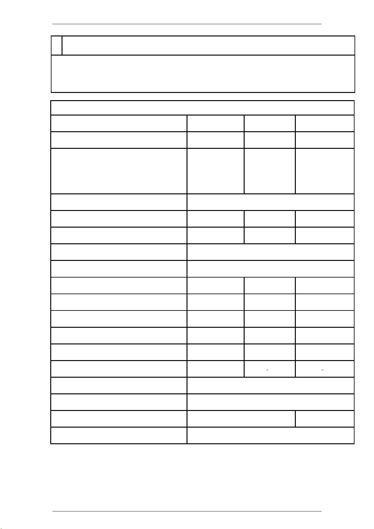
2. Antenna & Driver - Technical Specifications
Antenna model
Antenna Unit Type I/N ANT6X-001 ANT9X-001 ANT12X-001
Driver & Transceiver I/N: SRT/12-002
Antenna type End-fed-slotted wave guide
Antenna length (inch / mm.) 6’ / 1800 9’ / 2650 12’ / 3618
Antenna swing circle (/ mm.) 1800 2650 3618
Frequency (MHz) 9325 - 9425
Polarization Horizontal
Gain (dB) 29 31 32,5
Horizontal beam width at -3 dB 1,35° 0,9° 0,7°
6X 9X 12X
SRT/12-002
SRT/25-002
SRT/12-003
SRT/25-003
SRT/25-002
SRT/12-003
SRT/25-003
SRT/12-002
SRT/25-002
Vertical beam width at -3 dB 22° 22° 22°
Horizontal side lobes (‘dB):
- within 10° - 27 - 26 - 26
- outside 10° - 30 - 30 - 30
VSWR Better than 1.20
PPR 128 / 1024 with encoder
Nominal Rotation speed (RPM) > 40 > 20
Nominal Wind resistance (KT) 100
304202P003 1.13 Rev. C
Page 38
SRT X-BAND RADAR SYSTEMS
DESCRIPTION AND MAIN CHARACTERISTICS
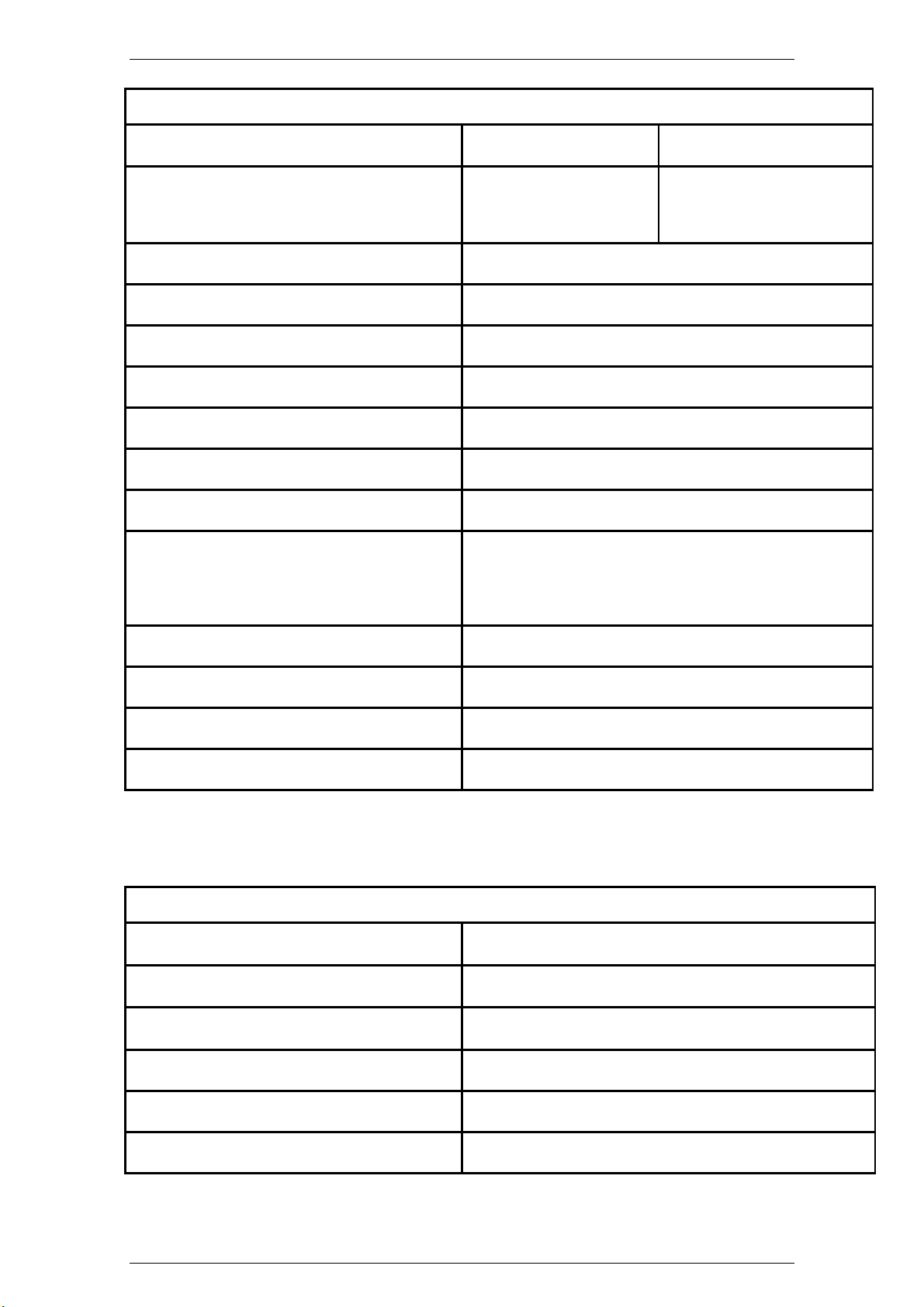
3. X Band Transceiver - Technical Specifications
Nominal peak power (KW):
Transceiver I/N: SRT/12-002
Operating frequency (MHz): 9375 ± 30 or 9410 ± 30 (X Band)
Pulse length (nsec.): 60 - 250 - 800
PRF (Hz): 3000-1500-750
Modulator: MOSFET Solid state
IF amplifier: Logarithmic
IF dynamic (dB) 100 (+30 pre STC)
IF center frequency (MHz) 60
IF bandwidth (MHz):
- short pulse
- medium pulse
- long pulse
20
4,8
1,5
12/10 (*) 25
SRT/12-003
SRT/25-002
SRT/25-003
Overall noise figure (nominal dB) ≤ 5
MDS on long pulse (dBm) ≤ -110
- Overall at receiver level ≤ -100
- At IF level ≤ -110
(*) EEV 4
rth
generation magnetron is 10.5 KW, NJRC is 12 KW
4. Environmental features
Operating temperature
Storage temperature
Relative humidity
Vibrations As for IEC 60945
-25°C / +55°C As in IEC 60945
-25°C / +70°C As in IEC 60945
Up to 95% at +40° As for IEC 60945
Water proof according to IP 66
Wind resistance (KT) 100
304202P003 1.14 Rev. C
Page 39
SRT X-BAND RADAR SYSTEMS
DESCRIPTION AND MAIN CHARACTERISTICS
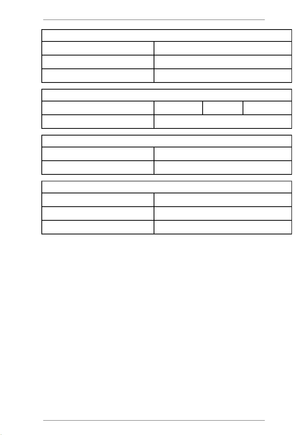
5. Dimensions (mm)
Width 364
Depth 534
Height 391
6. Weights (Kg)
Antennas (6X / 9X / 12X) 5 9 14
Pedestal with Transceiver 35
7. Required Power Supply
Standard configuration 24 VDC or 115/220 VAC
Power consumption: Ca 350 W Peak at maximum wind load
8. Options
Different PRF set
Heaters
Encoder 1024 pulses
Upon Customer request
For very cold environments (< -25° C)
Upon Customer request
304202P003 1.15 Rev. C
Page 40

SRT X-BAND RADAR SYSTEMS
OPERATION
CHAPTER 2
OPERATION
2.1 Introduction
2.1.1 Purpose
The present chapter provides the operating instructions, information and procedures required
in order to enable operating personnel to efficiently and effectively operate the SRT X-BAND
Radar System, for it to accomplish its designated tasks.
The Chapter is divided in:
Paragraph 2.2 Controls and Indicators
Paragraph 2.3 Semi-operative Controls
The Unit does not require personnel on steady watch conditions, but requires general
monitoring during normal operating situations. Since, the Unit has no operating controls,
paragraph 2.2 is not applicable. All semi-operative controls are located inside the unit.
2.2 Controls and Indicators
Since the Unit has no operating controls, this paragraph is not applicable.
2.3 Semi-operative Controls
The unit is fitted with some semi-operative controls, which are accessible, when the front
cover is open.
Table 2.3.1 - Semi-Operative Controls Location of TXRX Cabinet
Fig. Pos.
Figure 9.1.4 9 S1
Code
(Ref. Assy)
(Electronics
Rack)
Type Function
Interlock TXRX cover interlock switch for disabling the
High Voltage generation
304202P003 2.1 Rev. C
Page 41
SRT X-BAND RADAR SYSTEMS
OPERATION
Table 2.3.2 - Semi-Operative Controls Location of Electronic Rack
Fig. Pos.
Figure
Code
(Ref. Assy)
6 S1 10 position
9.1.17
Figure
2 DL1 LED green It indicates the presence of the +24VDC
9.1.10
Figure
3 DL2 LED green It indicates the presence of the +5V
9.1.10
Figure
4 DL3 LED red It indicates the presence of High Voltage
9.1.10
Figure
6 DL4 Red and
9.1.10
Type Function
It selects the TXRX unit operation mode as
rotary
switch
follow:
Pos. Function
0 SRT under external control 1
1 SRT under external control 2
2 SRT in local stand-by
3 SRT in local with short pulse
4 SRT in local with medium pulse
5 SRT in local with long pulse
9 SRT in local with long pulse and
performance monitor with auto
tuning and antenna rotation
power supply
Green indicates when Line Voltage is ON
Green
Red indicates that the PCB is in operation.
Table 2.3.3 - Semi-Operative Controls Location of Brushless Motor Controller
1
2
Code
(Ref. Assy)
Type Function
DL1 LED green It indicates the presence of the +50 VDC
power supply
DL2
LED red
It indicates the status of the controller:
Light on = motor in OFF or controller in
protection
Light off = motor in rotation
Fig. Pos.
Figure
9.1.32
Figure
9.1.32
304202P003 2.2 Rev. C
Page 42

SRT X-BAND RADAR SYSTEMS
OPERATION
2.4 NMEA Transfer Protocol
2.4.1 Abbreviations
RDC Radar Display Console
TXRX Transceiver (TX/RX)
CRC Checksum Field
Field Type
Field type Symbol Definition
Status A A = Yes, data valid, warning flag clear.
Variable Numbers x.x Variable length integer or floating numeric field. Op-
Fixed HEX field hh- Fixed length HEX number only, MSB on the left.
Variable text c—c Variable length valid character field.
Fixed alpha field aa- Fixed length field of upper-case or lower-case alpha
Fixed number field xx- Fixed length field of numeric characters.
Fixed text field cc- Fixed length of valid characters.
• NOTE ¹ Spaces shall only be used in variable text fields.
• NOTE ² A negative SIGN “-“ (HEX 2D) is the first character in a field if the value is
V = No, data invalid, warning flag set.
tional leading and trailing zeros. The decimal point
and associated decimal fraction are optional if full
resolution is not required (example: 73.10 = 73.1 =
073.1 = 73).
characters.
negative. When used, this increases the specified size of fixed length fields by one.
The sign is omitted if the value is positive.
304202P003 2.3 Rev. C
Page 43

SRT X-BAND RADAR SYSTEMS
OPERATION
2.4.2 DATA TRANSMISSION FROM RDC TO TXRX (OR
INTERFACES)
2.4.2.1 OPERATIONAL CONTROL SENTENCE 2
$PCO2,x,a,aa,aaa,a,a,a,a,hh,a*hh<CR><LF>
│ │ │ │ │ │ │ │ │ └─ MGN Heater: W = warm, C = cold else NULL (AUTO)
│ │ │ │ │ │ │ │ └─ Tuning adjust (min 00H, max FFH). If Automatic don't care.
│ │ │ │ │ │ │ └─ M = Manual Tuning, A = Automatic Tuning
│ │ │ │ │ │ └─ V = Video test else NULL (OFF)
│ │ │ │ │ └─ P = Performance Monitor ON else NULL (OFF)
│ │ │ │ └─ J = Jitter ON else NULL (OFF)
│ │ │ └─ Rxx = Antenna Rotating ON with xx RPM ( 01 ÷ 60) else NULL (OFF)
│ │ └─ Transceiver control (³)
│ └─ M = Request Master of Transceiver, S = Slave (²)
└─ Selected Transceiver Number (¹)
Notes:
(¹) Transceiver Number: 1, 2, 3, 4 (SPARE in stand alone TXRX)
(²) Master/Slave request (SPARE in stand alone TXRX and single equipments)
(³) Transceiver control:
Field type Field Descriptions
SB
SH
SM
SL
MM
ML
LL
Stand By
Short pulse, High frequency
Short pulse, Medium frequency
Short pulse, Low frequency
Medium pulse, Medium frequency
Medium pulse, Low frequency
Long pulse, Low frequency
2.4.2.2 SECTOR BLANKING SENTENCE
$PSE2,a,xxx.x,xxx.x,xxx.x,xxx.x*hh<CR><LF>
│ │ │ │ │
│ │ │ │ └─ End Sector 2
│ │ │ └─ Start Sector 2
│ │ └─ End Sector 1 (¹)
│ └─ Start Sector 1
└─ D = Sector Blanking Values, R = Sector Blanking Request (2)
Notes:
(¹) Start & End Sector units are degree. Es: 90.6.
This value will be rounded depending from the position sensor used
(2) If Sector Blanking Request, don't care
304202P003 2.4 Rev. C
Page 44

SRT X-BAND RADAR SYSTEMS
OPERATION
2.4.2.3 TIMERS INITIALIZATION
$PTIM,x,x,x,x.x,x.x,x.x,x.x,x.x,x.x,x.x*hh<CR><LF>
│ │ │ │ │ │ │ │ │ │
│ │ │ │ │ │ │ │ │ └─ Timer M-Pulse Low Freq.
│ │ │ │ │ │ │ │ └─ Timer S-Pulse Low Freq.
│ │ │ │ │ │ │ └─ Timer S-Pulse Medium Freq.
│ │ │ │ │ │ └─ Timer L-Pulse Low Freq. (²)
│ │ │ │ │ └─ Timer M-Pulse Medium Freq.
│ │ │ │ └─ Timer S-Pulse High Freq.
│ │ │ └─ Timer Standby
│ │ └─ Status 3
│ └─── Status 2
└───── Status 1 (¹)
Notes:
(¹) Command 1: 1 = Request for transmission of actual values
2 = Initialization of values .
3 = Reset of values.
Command 2: Spare
Command 3: Spare
(²) Timers : Integer value to pre-set the operated time. LSB is equal to 1 hour.
If Command 1 = 1 or Command 1 = 3 don't care.
2.4.2.4 DIGITAL POTENTIOMETERS
$PDPC,a,x,x*hh<CR><LF>
│ │ │
│ │ └─ Potentiometer increment signed value (³)
│ └─ Potentiometer ID (²)
└─ R = potentiometer value Request, F = potentiometer Factory preset else
NULL(¹) A = auto adjust (°)
Notes:
(¹) Factory preset is available for latest TX/RX versions.
(²) Pot. ID
#Potentiometer to be upgraded:
0 PRE-STC AMPLITUDE
1 PRE-STC SLOPE
2 P.M. OPEN
3 P.M. DISTANCE (Power Level)
4 TUNING INTICATION
5 TUNE OFFSET
304202P003 2.5 Rev. C
Page 45

SRT X-BAND RADAR SYSTEMS
OPERATION
6 NOISE DIODE CURRENT
(³) Increment or decrement to apply ( range ±7). (NEVER SEND 0)
(°) If “A” with pot id, adjust only the correspondent Pot. (not yet).
If “A” without pot id (,,), adjust all the auto adjustable (Tune offset for now).
Sentence should be sent under operator request only. Application of value is immediate but
storage of this one (not volatile memory) will take place after 20 seconds from last change i.e.
from last DPC sentence reception.
2.4.3 DATA TRANSMISSION FROM TXRX TO RDC
2.4.3.1 STATUS SENTENCE 2
$PST2,x,a,aa,aaa,a,a,a,a,a,hh,a,a,,a*hh<CR><LF
│ │ │ │ │ │ │ │ │ │ │ │││
│ │ │ │ │ │ │ │ │ │ │ ││└─ Protocol Version (Starting from A)
│ │ │ │ │ │ │ │ │ │ │ │└─ Empty Field
│ │ │ │ │ │ │ │ │ │ │ └─ MGN Heater: W = warm, C = cold else NULL (N.A.)
│ │ │ │ │ │ │ │ │ │ └─ A = Automatic Tuning ON else NULL (OFF)
│ │ │ │ │ │ │ │ │ └─ Manual Tuning Adjust. If Automatic NULL (Don't care)
│ │ │ │ │ │ │ │ └─ P = Performance Monitor Available else NULL (N.A.)
│ │ │ │ │ │ │ └─ S = Service Mode A = Auto Adjust. else NULL (OFF)
│ │ │ │ │ │ └─ W = Warm Up, R = Ready
│ │ │ │ │ └─ X = X-Band , S = S-Band Transceiver
│ │ │ │ └─ J = Jitter ON else NULL (OFF)
│ │ │ └─Rxx = Antenna Rotating ON with xx RPM ( 01 ÷ 60) else NULL (OFF)
│ │ └─ Transceiver status (³)
│ └─ M = Acknowledge Master, S = Slave (²)
└─ Transceiver Number (¹)
Notes:
(¹) Transceiver Number: 1, 2, 3, 4 (NULL in stand alone TXRX)
(²) Master/Slave acknowledge (NULL in stand alone TXRX)
(³) Transceiver status:
Field type Field Descriptions
SB
SH
SM
SL
MM
ML
LL
Stand By
Short pulse, High frequency
Short pulse, Medium frequency
Short pulse, Low frequency
Medium pulse, Medium frequency
Medium pulse, Low frequency
Long pulse, Low frequency
2.4.3.2 DATA SENTENCE
$PDAT,hh,hh,hh,xxx,xx,xxx,x*hh<CR><LF>
│ │ │ │ │ │ │
304202P003 2.6 Rev. C
Page 46

SRT X-BAND RADAR SYSTEMS
OPERATION
│ │ │ │ │ │ │
│ │ │ │ │ │ └── Software Revision (From A to Z)
│ │ │ │ │ └── Warm Up time (²)
│ │ │ │ └── Txrx Program Software Version (> 80)
│ │ │ └── Inner transceiver temperature (¹)
│ │ └── Magnetron Peak Current (Range 00H ± FFH).
│ └── Main Bang Amplitude (Range 00H ± FFH).
└── Power Level (Range 00H ± FFH).
Notes:
(¹) Transceiver temperature: From -99 to 99 Celsius degree (signed value).
(²) Warm Up time: calculated in seconds, when null becomes TXRX READY.
Value of power level, main bang and magnetron peak current during sector blanking are frozen.
2.4.3.3 TIMERS INFORMATION
$PTIM,c--c,x.x,x,x.x,x.x,x.x,x.x,x.x,x.x,x.x,x.x,a*hh<CR><LF>
│ │ │ │ │ │ │ │ │ │ │ │
│ │ │ │ │ │ │ │ │ │ │ └─ Timers validity: A = valid V = invalid
│ │ │ │ │ │ │ │ │ │ └─ System timer (4)
│ │ │ │ │ │ │ │ │ └─ Timer M-Pulse Low Freq.
│ │ │ │ │ │ │ │ └─ Timer S-Pulse Low Freq.
│ │ │ │ │ │ │ └─ Timer S-Pulse Medium Freq.
│ │ │ │ │ │ └─ Timer L-Pulse Low Freq. (3)
│ │ │ │ │ └─ Timer M-Pulse Medium Freq.
│ │ │ │ └─ Timer S-Pulse High Freq.
│ │ │ └─ Timer Standby
│ │ └─ Status 3
│ └─── Status 2 (2)
└───── Status 1 (¹)
Notes:
Status 1 (¹) : Magnetron Type label
Status 2 (2) : Integer value indicating the magnetron end of life, from 0 to 999, > 100 mean
end of life.
Status 3 : Spare
(3)Timers : Integer value indicating the operated time. LSB is equal to 1 hour.
(4)System : Integer value indicating lifetime of transceiver LSB is equal to 1 hour
2.4.3.4 DIGITAL POT. INFORMATION
$PDPI,xx,xx,xx,xx,xx,xx,xx*hh<CR><LF>
304202P003 2.7 Rev. C
Page 47

SRT X-BAND RADAR SYSTEMS
OPERATION
│ │ │ │ │ │ │
│ │ │ │ │ │ └─ Pot ID #6, PM Noise diode current
│ │ │ │ │ └─ Pot ID #5, Tuning Offset
│ │ │ │ └─ Pot ID #4, Video Level
│ │ │ └─ Pot ID #3, Performance Monitor Amplitude
│ │ └─ Pot ID #2, Performance Monitor Opening
│ └─ Pot ID #1, STC Slope
└─ Pot ID #0, STC Amplitude
Notes:
Potentiometer decimal Value : Range 0 ÷ 99.
2.4.3.5 SECTOR BLANKING SENTENCE
$PSE2,,x.x,x.x,x.x,x.x*hh<CR><LF>
│ │ │ │
│ │ │ └─ End Sector 2
│ │ └─ Start Sector 2
│ └─ End Sector 1 (¹)
└─ Start Sector 1
Notes:
(¹) Start & End Sector units are degree. Es: 90.6.
2.4.3.6 WRONG COMMAND RETURN (NACK)
$PNAC,x,aaa,xx,xx*hh<CR><LF>
│ │ └─ Error Code (²)
│ └─ Refused Sentence (if recognized) (¹)
└─ Transceiver Number (as sentence STS or NULL in stand alone TX/RX )
Notes:
Meaning: same feedback error directly from TXRX
│ │ │ │
│ │ │ └─ Wrong field (³)
(¹) See list of accepted sentences
(²) Numeric value, from 0 to 99, command dependent (see list below)
(³) Field number. Incremental from 1 after sentence code.
Es. 1:
Meaning: feedback on error inside COP command for transceiver 2 through TXRX Interface,
error type #01, field #05 (wrong JITTER field)
Es. 2:
-
$PNAC,2,COP,01,05*hh<CR><LF>
$PNAC,,COP,01,37*hh<CR><LF>
2.4.3.7 HEALTH SENTENCE 2
304202P003 2.8 Rev. C
Page 48

SRT X-BAND RADAR SYSTEMS
OPERATION
$PHT2,a,a,a,a,a,a,a,a,a,a,a*hh<CR><LF>
│ │ │ │ │ │ │ │ │ │ │
│ │ │ │ │ │ │ │ │ │ │
│ │ │ │ │ │ │ │ │ │ └── INTERLOCK test : A = Transceiver safety door CLOSED
│ │ │ │ │ │ │ │ │ │ V = Transceiver safety door OPEN
│ │ │ │ │ │ │ │ │ └── FE MONITOR test : A = Front End OK
│ │ │ │ │ │ │ │ │ V = Front End Fail
│ │ │ │ │ │ │ │ │
│ │ │ │ │ │ │ │ └── -15VDC Voltage test : A = Test valid (value in range)
│ │ │ │ │ │ │ │ V = Test invalid (value out of range)
│ │ │ │ │ │ │ │
│ │ │ │ │ │ │ └── 15ISO Voltage test : A = Test valid (value in range)
│ │ │ │ │ │ │ V = Test invalid (voltage out of range)
│ │ │ │ │ │ └─── +15 VDC Voltage test : A = Test valid (value in range)
│ │ │ │ │ │ V = Test invalid (voltage out of range)
│ │ │ │ │ │
│ │ │ │ │ └── Line Input (24/50v, Voltage test : A = Test valid (value in range)
│ │ │ │ │ V = Test invalid (voltage out of range)
│ │ │ │ └── LINK flag (³)
│ │ │ └── CRC ERROR RECEPTION (²)
│ │ └── Safety Controls : A = Test valid ( safety sw. close )
│ │ V = Test invalid (safety sw. open) (¹)
│ └── Magnetron Heater, Voltage test : A = Test valid (value in range)
│ V = Test invalid (voltage out of range)
└── +24 VCO, Voltage test : A = Test valid (value in range)
V = Test invalid (voltage out of range)
Notes:
LINK flag: Valid if Rx data are received.
Invalid if Rx data are NOT received. (time-out)
CRC ER: Invalid each time a crc error in Rx data will be found.
2.4.3.8 DATA SENTENCE 3
$PDT3,x.x,x.x,x.x,x.x,x.x,x.x,x.x,hhhh*hh<CR><LF>
│ │ │ │ │ │ │ │
│ │ │ │ │ │ │ └─ Prog. Config. 16 bits in hex format (Not in use)
│ │ │ │ │ │ └─ +5VDC Voltage
│ │ │ │ │ └─ -5VDC Voltage
│ │ │ │ └─ -15VDC Voltage
│ │ │ └─ Line Voltage +24 / 50 VDC
│ │ └─ +15 VDC Voltage
│ └─ +24 VCO VDC Voltage
└─ Heater Voltage
Each value of voltage is integer and millivolt.
304202P003 2.9 Rev. C
Page 49

SRT X-BAND RADAR SYSTEMS
OPERATION
2.4.4 GENERAL NOTES
1) Rates:
Data transmission rate to TXRX should be:
Sentence CO2 1 Hz normally, or when is necessary
Sentence SE2 when is necessary upgrade Sector Blanking
Sentence TIM every time is necessary timers information or reset values
Sentence DPC every time is necessary digital potentiometer information or value upgrade
Sentence CFG only for first setup
Sentence SPD only for first setup and when the motor controller is changed
Rate shall be not faster than 50ms between two consecutive sentences.
Data transmission rate from TXRX are:
Sentence ST2 1 Hz normally
Sentence DAT connection depending : 1 Hz (Interfaces) or 150ms (TXRX).
Sentences DPI, SE2 on request
Sentences TIM, on request and each 30 minutes of interval after power on.
Sentence NAC when necessary
Sentences HT2 1 Hz normally
Sentences DT3 1 Hz normally
Sentences CFG on request.
Sentences SPD on request
.
2) Error Code:
MESSAGE ERROR CODE MEANING
CO2
SEC
TIM
DPC
CFG
00 CRC ERROR
01 Field not in compliance with specification
02 Missing transceiver control
00 CRC ERROR
01 Field not in compliance with specification
02 Wrong sector value
00 CRC ERROR
01 Field not in compliance with specification
02 Missing command type
03 Initialization value outside limits
00 CRC ERROR
01 Field not in compliance with specification
02 Wrong potentiometer ID
03 Potentiometer value outside limits
00 CRC ERROR
01 Field not in compliance with specification
304202P003 2.10 Rev. C
Page 50

SRT X-BAND RADAR SYSTEMS
FUNCTIONAL DESCRIPTION
CHAPTER 3
FUNCTIONAL DESCRIPTION
3.1 Introduction
The present chapter provides the functional and detailed description of the main
functions and operations performed by the SRT X-BAND RADAR SYSTEM.
Functional diagrams are used to depict signal processing whilst the text is used
to support diagrams as necessary for explanation purposes.
The descriptions are structured in paragraphs as described in what follows:
Paragraph 3.2 - Functional Description, provides a general functional
description, functional areas identification and main interconnections among
them. This allows highlighting the main functions relationship and unit
performance. As a functional area it is intended a group of circuits, or other
devices, which operate together to accomplish a well defined function. Each of
the major functions of the unit shown in the functional block diagram (Chapter 9,
Figure 9.1.7 and Figure 9.1.8) is described in details on separate functional
block diagrams whose description is given as follows:
Paragraph 3.2.1 Electronics Rack
Paragraph 3.2.2 RF HEAD
Paragraph 3.2.3 Brushless Motor Controller
Paragraph 3.2.4 Motor Unit
Paragraph 3.2.5. Optional Unit: SRT Adapter Box
Paragraph 3.2.6. Optional Unit: Heater
Paragraph 3.2.7. Optional Unit: Encoder
Functional block diagrams show the development of a function from input to
output in detail. Main assemblies and subassemblies (modules and cards) are
shown and identified by code name and part number (P/N).
Hardware blocks are used in the signal paths to describe the processing
functions performed. For a better understanding, the signal functions on circuit
blocks are tagged by letters whose meanings are described in the list of
abbreviations Table 1.1.1 - List of abbreviations.
Signal flows are mainly laid down from left to right and from top to bottom
therefore subassemblies can be illustrated more than once to ensure logical
signal flow. Signals, on functional block diagram, appear with their official code
name as indicated on the manufacturer electric schematic diagrams and tabular
interconnection lists.
Comments for explanation purpose on signal paths are within parenthesis; this
sometimes identifies their operational accomplishment. Timing diagrams and
word-code bit structure figures are also given as necessary for a better
understanding of the described function. Logic terms and principles used in this
technical manual comply with standard engineering practices.
304202P003 3.1 Rev. C
Page 51

SRT X-BAND RADAR SYSTEMS
FUNCTIONAL DESCRIPTION
Logic symbols (gates) are used, if they represent more appropriately, in a
simplified form, the logic function performed even by complex parts of
hardware.
Where necessary, functional description of power supplies and minor
assemblies are referred to schematic diagrams.
NOTE
The schematic block diagrams of Chapter 3 show all the
functions that the boards’ hardware could potentially support,
while the related functional description refers only to the
functions implemented in the present customized configuration.
3.2 Functional Description
On the basis of the SRT X-BAND RARAR SYSTEM functional block diagram
shown in Chapter 9, Figure 9.1.7, the equipment can be subdivided into the
following main assemblies:
− Electronics Rack
− RF Head
− Brushless Motor Controller
− Motor Unit
There are also a number of optional functions which are also described below,
as:
• The SRT Adapter Box
• Heaters
• Encoder
3.2.1 Electronics Rack
The Electronics Rack block diagram is shown in Chapter 9, Figure 9.1.7 and
Figure 9.1.8. Each block represents a functional area which is described in
detail in the following function of the present chapter (paragraphs 3.3 through
3.7). The blocks indicated by dotted lines represent circuits assembled on the
equipment chassis.
This is concerning all the blocks diagrams of this chapter.
Basically, the unit performs the following functions:
− it generates the power supply voltages required for the unit’s functioning
− it generates the R.F. pulses which will be radiated by the Antenna; the
pulses, in X-band wave length (9375 ±30 MHz for NJRC or 9410 ±30
MHz for EEV Magnetrons) and with 12 (10 for EEV Magnetrons) or 25
kW peak nominal power, can be selected among the following:
304202P003 3.2 Rev. C
Page 52

SRT X-BAND RADAR SYSTEMS
FUNCTIONAL DESCRIPTION
Pulse Type Duration PRF
SHORT PULSE
MEDIUM PULSE
LONG PULSE
− it receives the echoes reflected from targets and it converts and amplifies
them
− it monitors the unit’s correct operations
nominal 60 ns 3000 Hz
nominal 250 ns 1500 Hz
nominal 800 ns 750 Hz
3.2.1.1 SRT Power Board
The SRT Power (Chapter 9, Figure 9.1.11) is divided into 2 units, LVPS and
HVPS; it generates all the voltage sources needed by the electronics rack from
the original 50 VDC (40÷60).
The SRT Power unit is equipped with protection circuits to avoid wrong polarity
connection, over current and over voltage spikes. A voltage sensor is connected
with microprocessor interrupt request input to provide save state function in
case of voltage fall under 40 VDC and to safely perform system shut down
without data loss.
3.2.1.2 SRT Power - Low Voltage Power Sup-
ply
The LVPS’s function (Chapter 9, Figure 9.1.13) is to generate the low DC
voltages, necessary to supply the SRT electronic circuits. As input, the circuit
receives the 50 VDC voltage. This voltage filtered and stabilized by suitable
solid state components in order to get as output:
− +5 V, -5 V, +15 V, - 15 V, +15V Iso, +24V to supply all the other
electronic circuits
− VFIL, Magnetron Heather in accordance with selected Pulse and
magnetron type.
3.2.1.3 SRT_Power - High Voltage Power
Supply
The H.V.P.S. Generator Circuit’s function (Chapter 9, Figure 9.1.14) is to
generate the high voltage (700 V) necessary to pulse transformer and to the
Magnetron for the transmission pulse generation. The signals used in this circuit
are:
304202P003 3.3 Rev. C
Page 53

SRT X-BAND RADAR SYSTEMS
FUNCTIONAL DESCRIPTION
− 50 VDC (VMOD)
− HVON from Gate Array of SRT Control Board
− LPA (Long Pulse Adjustment), MPA (Medium Pulse Adjustment) and
SPA (Short Pulse Adjustment) from Gate Array of SRT Control Board
− HVSTOP from SRT MOS board.
The H.V.P.S. starts functioning when the signal, output from the
COMPARATOR, is active; the signal is active when:
− the signal HVON, from the Gate Array of SRT Control Board, is LOW;
this signal is forced to high, inactive, when:
o 3 min. period isn’t yet passed since TXRX has been turned on
o TXRX is in standby mode
o safety switch or interlock is open.
o +15V is ≤ 14V or ≥ 16V
o VFil (6.3V) is ≤ 5V or ≥ 7V
− input voltage supply is over 40 VDC
− the signal HVSTOP is Low, which disables the functioning of the circuit
when the +15 ISO voltage is absent.
− the HVPS Generator Circuit generates the correct high voltage value.
When the high voltage is generated, the COMPARATOR sends to the Gate
Array of the SRT_Control board the signal HVOK and the red LED DL3
(HVOK), mounted on the SRT_Power lights-up.
The VMOD is applied to the primary of the HVPS TRANSFORMER which,
driven by the MOSFET, generates as output the required high voltage (700 V).
The Mosfet enabling is controlled by a circuit, which, also protects the
MOSFET, itself.
The circuit is composed by the blocks COMPARATOR, POTENTIOMETER and
FLYBACK CONTROLLER. When the COMPARATOR recognizes HVON signal
to be low, enables the FLYBACK CONTROLLER that in turn enables
transformer Mosfet output; in the feedback loop another comparator assures
that high voltage value is stable and correct. This action is performed by
potentiometers and LPA, MPA and SPA signals. In this way, it is possible to
control the Magnetron output power.
HVPS unit generates an additional 150 V voltage for a neon lamp performance
monitor, for future use.
3.2.1.4 SRT_Mos Board
Two configurations are available one for 12 KW and one for 25 KW, the number
of MOSFET transistor switched differ in these two versions.
Basically the SRT_Mos board (Chapter 9, Figure 9.1.16) performs the following
main function: High Voltage Pulses generation for Magnetron.
304202P003 3.4 Rev. C
Page 54

SRT X-BAND RADAR SYSTEMS
FUNCTIONAL DESCRIPTION
The Pulse Circuit Generator’s function is to generate the necessary high voltage
supplying the Magnetron, according to the previous selections.
The Input Pushing Trigger is TRPUSH and the input Pulling Trigger is TRPULL;
both from SRT_CONTROL Board. To the Pulse Circuit Generator is applied as
well the 700 V from the HVPS Generator Circuit.
To one terminal of the primary windings of the PULSE TRANSFORMER is
applied the 700V whilst the second terminal is connected to the MOSFET (push
and pull).
The pulse is generated in accordance with TRPULL and will be pushed in
accordance with TRPUSH; in fact there is current only when the Transformer is
grounded with the TRPULL. Every time there is 700 V on the primary, there is,
as well, 6 kV on the secondary windings of the PULSE TRANSFORMER.
According with this configuration the R.F. is sent to the antenna from the
Magnetron.
In order to get the best operating conditions for the Magnetron, there is also a
need to energize magnetron filament with a 6.3 V Filament Voltage (voltage
changes slightly depending from the magnetron installed, EEV or NJRC and 12
and 25 kW), named VFIL which is applied to a section of the secondary
windings of the PULSE TRANSFORMER. As result, the signal FIL. sent to the
Magnetron, has always a potential 6.3 V greater than the K potential.
While the SRT is Transmitting, the CURRENT TRANSFORMER generates the
signal MCUR which:
− is used in this circuit to block high voltage to magnetron when current
absorbed by magnetron is too high.
− is sent to the Gate Array of the SRT_Control Board
− is sent to the Microprocessor of the SRT_Control Board
3.2.1.5 SRT_Control Board
The SRT_CONTROL Board (Chapter 9, Figure 9.1.18) is located in the
Electronic assy, and his function is to control all SRT operations.
The SRT_CONTROL Board is divided in the following main circuits
− Microprocessor and Gate Array
− System monitor
− Performance Monitor
− Input and Output Interface
304202P003 3.5 Rev. C
Page 55

SRT X-BAND RADAR SYSTEMS
FUNCTIONAL DESCRIPTION
3.2.1.6 Microprocessor and Gate Array
3.2.1.6.1 General Description
PCB
The heart of SRT_Control Board, is an advanced 32 Bit MCU (Micro-controller
Unit) (Chapter 9, Figure 9.1.18), with highly sophisticated, on chip, peripheral
capabilities and performing the function of:
− managing all functions of the SRT unit on the basis of
commands/data from the Display Unit
− preparing the feed-back signals to be sent out to the Indicator unit
− executing all internal processing to assure the SRT units control
and monitoring
The Microprocessor used in the board is the MCF5211 with these
characteristics:
− 16 KB SRAM,
− 128 KB Flash Memory,
− Two UARTs,
− Queued serial peripheral interface (QSPI) with four peripheral chip
selects,
− Four 32-bit timer channels with DMA capability,
− Four 16-bit timer channels for capture, compare and pulse width
modulation (PWM),
− Four - channel 16-bit/8-channel 8-bit PWM generator,
− Two periodic interrupt timers (PITs) for alarm and countdown timing,
− Eight - channel 12-bit ADC
− System integration (PLL, SW watchdog)
− Up to 33 general-purpose I/O
The SRT unit management is performed by the Microprocessor that does not
require any external PROM or RAM elements. Its own memory, in fact, has
sufficient capacity to store the Operative Program. it is using an external U30
EEPROM, (Chapter 9, Figure 9.1.17 pos.7) for store transmitting parameters.
The necessary clock pulse of 50 MHz generated by the crystal oscillator.
In Chapter 9, Figure 9.1.19 are displayed the Microprocessor and Gate Array
general configuration, the main sub-systems and how they relate to the pins of
the MCU.
304202P003 3.6 Rev. C
Page 56

SRT X-BAND RADAR SYSTEMS
FUNCTIONAL DESCRIPTION
3.2.1.6.2 Functions Performed
The main functions performed by the Microprocessor with the Gate Array
(Chapter 9, Figure 9.1.20 and Figure 9.1.21), on the basis of commands and
selections, Remote, (from Display Unit) or Local, (Trough the Selector), are:
− to initialize the TXRX operations
− to generate the trigger pulse for SRT MOS Board and the trigger (TR)
pulse for the Display Unit and the P.M. function
− to generate the PRESTC waveform for the RF Detector Assy (STC) and
the selection commands for band-width of Receiver
− to generate:
. the VCO forwarded to Mixer
. the control signals forwarded to SRT MOS and SRT
Power Boards
− to receive the signals producing the Antenna rotation
− to perform the processing on various sensor signals in order to monitor
the correct operations of the TXRX unit
3.2.1.6.3 Microprocessor Output Signals
PCB
TR Transmission Trigger.
CS0, CS1, SCK, SO Serial Gate Array and EEprom management signals
TX Asynchronous serial transmission
/RES Asynchronous Reset
3.2.1.6.4 Microprocessor Input Signals
PCB
VDLEVEL Main bang Video signal level the value is send, in serial
mode, to the Display Unit
PWLEVEL Information about the Power Level; the value is send, in serial
mode, to the Display Unit
MCUR Magnetron cathode current pulse sample the value is send, in
serial mode, to the Display Unit
VFIL M VFil Voltage value
24 VCO M +24Vco Voltage value.
12 VT 40 to 60VDC Main Power Voltage value
15 M +15V Voltage value.
304202P003 3.7 Rev. C
Page 57

SRT X-BAND RADAR SYSTEMS
FUNCTIONAL DESCRIPTION
TEMP Temperature value; the value is send, in serial mode, to the
Display Unit
+5V M + 5V Voltage value.
- 5V M - 5V Voltage value.
- 15V M - 15V Voltage value.
Monitor M Information about the L.N.F.E. status.
AZ Antenna azimuth pulse
HL Antenna ship reset pulse
RX Asynchronous serial receive
IRQ Video data Reception/Transmission Interrupt.
NMI Power supply line absence.
CK10 50 MHz clock
SCK, SI Serial Gate Array management signals
3.2.1.6.5 Gate Array Input Signal
PCB
CK50 Input for the 50 MHz clock.
ANTBLK High voltage generation and antenna rotation disabling from
the Safety Switch.
SLK High voltage generation and antenna rotation disabling from
the interlock.
LINE Main power supply voltage
HV OK High voltage supply feedback
HV Stop Feedback from SRT MOS board for +15Iso presence
MPLC Magnetron transmission current.
P1 and P2 Links for the board configuration.
S1 selector 4 bit for the selector position.
TR Transmission Trigger.
CS1, SCK, SO Serial Gate Array management signals
TRSTC Pre-trigger for the STC generation.
RXCOMB Serial reception of the combined video.
304202P003 3.8 Rev. C
Page 58

SRT X-BAND RADAR SYSTEMS
FUNCTIONAL DESCRIPTION
3.2.1.6.6 Gate Array Output Signal
PCB
DATA BUS Bit DB0-DB7 of the Data Bus.
NMI Power supply line absence.
IRQ Video data Reception/Transmission Interrupt.
CK10 10 MHz clock
CS0-CS7 Digital potentiometer chip select.
U/D, INC Digital potentiometer control signals.
SWFIL1-2-3 Magnetron filament voltage control signals.
ANTS Antenna switch on signal.
SPA, MPA, LPA HVPS circuit control signals.
HVON HVPS circuit switch on signals.
SWB1-SWB2 Signals for the control of the NIFB bands.
TRPS Trigger PUSH for the transmission pulse generation.
TRPL Trigger PULL for the transmission pulse generation.
/TR Out Trigger for the display
/GSTC Gate for the STC signal generation.
TXCOMB Serial transmission of the combined video.
DIS TX Disabling for the combined transmission on the video.
TUNEN and /TUNEN Tuning detectors at transmission frequency
PM Out
SCK, SO Serial Gate Array management signals
3.2.1.6.7 Gate Array Pulse Length Generator
The Pulse Length Generator Function (Chapter 9, Figure 9.1.21) provides the
length of the generated pulse in accordance with the previous selections.
This function is performed by the Gate Array, which generates the signals
TRPS and TRPL when:
− the signal TR is active
− the signal HVOK is low
− the 50 MHz clock is present
− the signal RESET is high
− the signal LINE is true
− the signal SLK is high
− the signal ANTBLK is high
− Main Line ≥ 40VDC
304202P003 3.9 Rev. C
Page 59

SRT X-BAND RADAR SYSTEMS
FUNCTIONAL DESCRIPTION
The signals TRPS and TRPL are applied to the DRIVER which generates the
signals TRPUSH and TRPULL for the Pulse Generator circuit of the SRT_Mos
Board.
3.2.1.7 System Monitor Functions
System state monitor (Chapter 9, Figure 9.1.22) is performed by this unit. Unit is
composed of :
− Voltage Monitor
− Temperature Monitor
− SLK
− Safety switch
Voltage monitor performs monitoring of power supply voltage level. It receives
its inputs from the Voltage sensor of the SRT_Power Board.
Temperature monitor detects temperature value to be processed by the
microprocessor. In case of high value the microprocessor generates the signals
for switching the fan on through the Gate Array.
SLK is a signal from switch that disables transmission and antenna rotation
when the apparatus cover is open.
Safety switch disables the radar unit from hazardous power supply. The safety
switch must be operated when radar unit is under maintenance to prevent high
voltage hazard for operators.
3.2.1.8 Performance Monitor Functions
The Performance Monitor’s function is to monitor Transmission Power, Tuning
and Noise Figure in order to result in a Noise Ring presentation on PPI and for
to have the peak power value on TXRX DATA.
In the related circuit there is a diode, put inside the RF Head, operating as a
revelator when the magnetron send the power in output or as noise generator
when the signal PM_Out is available.
When the diode is operating as revelator, it is synchronized with the
transmission and the revelator circuit can detect the power present at the diode;
this circuit is always activated, the measurement is made every trigger and the
measured value is available on TXRX data.
When the command PMON, Performance Monitor ON, is inserted, the power
value and the tuning value are arranged to change PM_Out signal parameters.
The scope of this circuit is to introduce a noise ring on PPI. This noise ring
change its distance by the variation of the transmitting power and its thickness
by the variation of the tuning.
A neon lamp, placed in front of the Antenna, on a monitor arm extending from
the antenna pedestal, powered by 150 Voltage forwarded by POWER MOS
304202P003 3.10 Rev. C
Page 60

SRT X-BAND RADAR SYSTEMS
FUNCTIONAL DESCRIPTION
Board, is excited at each antenna scan by the radiated RF pulse energy, any
time the RF beam crosses over.
The result is, that when the Performance Monitor is switched on and the neon
lamp is radiated by the Magnetron RF, the RF energy causes a current variation
on neon lamp and on RM signal. A revelator circuit provides to detect this
variation that interrupts the Noise Ring
This function supplies to a general verification of the output power sent out.
3.2.1.9 Input and Output interface
The Input interface of the SRT_Control board receives input signals from SRT
Power, SRT MOS, RF Detector, Safety Switch, interlock and forwards them to
the microprocessor and to the gate array. Signal conditioning and level shifting
operation is accomplished by buffers, level translators and peak hold devices.
Azimuth (AZ-in) and Heading Line (HL-in) input signals are processed as well
and forwarded to the microprocessor and the gate array (AZ, HL)
The Output interface forwards processed signals from Gate Array, RF Detector,
Safety Switch and from the TX pin of the microprocessor to the Display, the RF
detector and the brushless motor controller.
3.2.1.10 Azimuth (AZ) and Heading Line (HL)
Signal Circuit Generator
The Antenna Unit must constantly forward its Azimuth position and Heading
Line to the Display Unit. The function of this circuit (Chapter 9, Figure 9.1.30) is
to process the incoming signals AZIN and HLIN and forward them to the
Microprocessor the signal AZ and HL for the blanking function.
The output signal AZOUT and HLOUT are used on the Display Unit.
3.2.2 RF HEAD
The RF Head (Chapter 9, Figure 9.1.23) is composed of a solid state controlled
MAGNETRON stage connected to a CIRCULATOR and ending with a flange to
be connected to a waveguide in order to transfer the RF PULSE to the Antenna
for it to be radiated. In the 25 kW system, there is also a Band Pass FILTER
included between the magnetron and the circulator to filter out spurious
frequency emissions.
The opposite end of the CIRCULATOR is fitted with the LIMITER, the
RF_Amplifer (L.N.F.E + RF_Detector). L.N.F.E (Low Noise and Front End) is
composed of: the IMAGE REJECTION FILTER, the LOW NOISE AMPLIFIER,
304202P003 3.11 Rev. C
Page 61

SRT X-BAND RADAR SYSTEMS
FUNCTIONAL DESCRIPTION
two-BALANCED MIXER and the LOCAL OSCILLATOR; RF_Detector is the
final amplification stage and it is of the logarithmic kind.
The RF Head is designed to generate RF pulses in the X-Band range up to 12
or 25 kW and to receive echo from targets.
During transmission time, the MAGNETRON receives a high voltage trigger
pulse, whose length ( short / medium / long ) is determined by the operator
settings on Display, and generates high power RF pulses in the X-Band range
until the high voltage pulse is applied to its cathode.
The RF energy generated is sent to the CIRCULATOR, and from this to the
waveguide which delivers the energy for the radiating Antenna.
The CIRCULATOR is a 3-way microwave device used either as a RF switch or
to send the transmission pulses to the Antenna or to apply the received echoes
to the Receiver.
The second function carried out by the RF HEAD unit is to convert, the
receiving R.F. energy, reflected from targets, into intermediate frequency, (I.F.)
and amplify it. This is provided by the R.F. HEAD block mainly consisting of:
− Limiter
− Integrated RF Amplifier composed of:
. Low Noise Front End (Low Noise Amplifier, Mixer, LO)
. RF Detector
The echo signal received by the Antenna arrives, through the Limiter and the
Low Noise Amplifier, to the Mixer where it is mixed with the signal forwarded by
the Local Oscillator. The resulting beat is the 60 MHz IF signal which is
forwarded to the RF_Detector. The Limiter is used to avoid an output above a
scheduled value. A higher output would cause a short-circuit.
The Low Noise Amplifier and the Image Rejection Filter are used to amplify the
echo signal in order to improve the noise figure of the receiver. The Local
Oscillator is integrated directly into the LNFE. It can be tuned up to the
Magnetron transmission frequency trough the VCO voltage level.
The RF Detector Assy’s function (Chapter 9, Figure 9.1.24 and Figure 9.1.25) is
to amplify the echo signals delivered by the RF HEAD Assy. It is composed of a
Group Amplifier stages, cascade connected, with specific components so to
obtain a logarithmic dynamic characteristic. The central frequency is 60 MHz
and the bandwidth is 1.8 MHz for Long Pulse, 4.5 MHz for Medium Pulse, 24
MHz for Short Pulse.
To maintain the target echo signals free from any possible external induction
that can degrade the performance of the Unit, the DC power supply voltages
and the band switching commands are applied to the module by means of a
FILTER.
3.2.3 Brushless Motor Controller
304202P003 3.12 Rev. C
Page 62

SRT X-BAND RADAR SYSTEMS
FUNCTIONAL DESCRIPTION
Speed controller board sets brushless motor rotation speed by means of variable voltage signal VEL coming from SRT_Control Board. An enable control 5V
signal is produced as well (start), for safety purpose. Turning the safety switch
off results in preventing motor from rotating (Chapter 9, Figure 9.1.26).
3.2.4 Motor Unit
The Motor Unit, on which 6' and 9' and 12 ´X-Band Antennas can be mounted,
is equipped with an Electric Motor powered by the Brushless Motor Controller
board in the casting (Chapter 9, Figure 9.1.5).
The motion is transferred to the X-BAND ANTENNA through 2 GEAR
REDUCTION GROUPS, with a total reduction ratio of 60:1.Note only for 6 and 9
feet per 12 feet is 120:1. The ANTENNA nominal angular speed can be ≥ 40
rpm.
On the Antenna shaft is mounted the OPTICAL READ-OUT group that
generates the pulses used to determine the Antenna position (Azimuth) and the
Heading Line.
The OPTICAL READ-OUT group is composed of a disk rotating with the
Antenna shaft and an optical sensor composed of two slotted optical switches.
When in front of the optical sensor passes a hole of the disk, a pulse is
generated by the Photo-transistor. The pulse is sent to the INTERFACE block of
the Electronics Rack through the SIGNAL CONDITIONER circuit, which adapts
the amplitude of the pulses from the Optical Read-out
The Heading Line pulses are obtained by means of another optical sensor,
equal to the previous one, which generates a pulse when a deeper hole passes
through the sensor.
On the SRT_Control board, it is applied a SAFETY SWITCH. This switch
positioned outside the equipment, when open, disables, in the SRT, the power
supply for the MOTOR and inhibits RF emission, thus achieving a safety
condition when personnel have to operate on the equipment both for
maintenance and for repairing. The wiring from the switch enters in the
equipment through the smaller stuffing tube. The installation is compulsory and
it is recommended to install the switch at the bottom of the mast stairs giving
access to the Unit.
NOTE
Before performing any service on the Antenna, SWITCH OFF
the Safety Switch.
304202P003 3.13 Rev. C
Page 63

SRT X-BAND RADAR SYSTEMS
FUNCTIONAL DESCRIPTION
3.2.5 Optional Equipment: SRT Adapter Box
It is possible to connect TRTX units to the Radar Display with lengths of 300 m
between.
To ensure adequate signal levels at this distances the SRT Adapter Box has
been introduced.
The SRT Adapter Box has the following functions:
• Ensure adequate Power supply level (of 50 V) for the TRTX even at long
cable lengths. A 480W AC/DC power supply with universal input from
85VDC to 250 VDC is located on the right part of the box.
• Safety switch location to interrupt the antenna rotation during maintenance.
• The Adapter PCB within the adapter box ensures correct signal buffering
and adjustment of signal levels (amplification) compensating for cable
losses.
• Decode the combined video and if needed convert older types of protocol
(as Mastermate) to new combined video protocol standards.
The decoding logic extracts the serial data packets, the trigger and bearing signals from the combined video and translated them in standard levels (for example 232/422 for serial lines)
Figure 9.1.36 shows the SRT Adapter Box PCB layout.
LED D9 is a dual red / green LED. When red the board receives from the display unit. When green transmitting to the display unit.
LED D10 is also a dual red/ green LED . When green, there is a proper signal
decoding is going on. When red, there is a parity error at decoding.
This latter LED works when the decoding function is enabled.
3.2.6 Optional Equipment: Heaters
Heaters are introduced for extreme cold environments, when the SRT Radar
System is expected to operate down to –40° C. The heater system consists of
cylindrical heater resistors mounted inside two cavities on the top part of the
transceiver. The heaters warm the inside electronics and the gearbox.
A controller PCB stops the heating when temperature is going over 0° C and
switches all the available power that is not used by the antenna rotation to the
heaters.
3.2.7 Optional Equipment: Encoder
The function of the Encoder is to increase the angular resolution of the azimuth
and heading signal to 1024 pulses for revolution.
304202P003 3.14 Rev. C
Page 64

SRT X-BAND RADAR SYSTEMS
PREVENTIVE MAINTENANCE
CHAPTER 4
PREVENTIVE MAINTENANCE
4.1 Introduction
This chapter provides the necessary information to execute the preventive
maintenance operations which must be carried out in order to ensure the SRT
X-BAND Radar System’s full efficiency.
The maintenance procedures are described in tabular form (Card); each card
lists the operations which must be performed, their periodicity, the personnel
required, the materials and the time required for their performance.
4.2 Preventive Maintenance Procedure
The preventive Maintenance procedures are given by means of cards. Each
card, besides indicating the operations to be performed during the maintenance
execution, lists the following indications:
− PERIODICITY: it is an alphanumeric code to identifying the maintenance
action described. The following periodicity symbols, as appropriate, are
used in the order of increasing periodicity interval as listed in the
following:
. M: Monthly
. S: Semi-annual
. A: Annually
. WR: When Required
− PERSONNEL: it indicates the number and the typology of the personnel
able to perform the maintenance operations; by making the assumption
that the qualification, knowledge, experience and skill needed to fulfill the
task assigned are proportional to the ranks. The following abbreviations
are used:
. ST: is a qualified persons with not less than ten years of
experience on the job
. JT: is a qualified person with more than four years of
experience on the job
. R: is a young technician with less than four years of
experience on the job, he can be either qualified or
undergoing qualification
− REQUIRED INSTRUMENTS: it indicates the tools or the instruments
which are used in the card operations; Table 4.2.1 - List of
Recommended Tools and Instruments lists the tools, the instruments and
the material required to perform the Preventive Maintenance operations.
− REQUIRED TIME: it indicates the total time required to perform the card
operations
304202P003 4.1 Rev. C
Page 65
SRT X-BAND RADAR SYSTEMS
PREVENTIVE MAINTENANCE
− SAFETY PRECAUTIONS: it indicates the precaution to be followed in
order to ensure a safe Preventive Maintenance operation execution
Table 4.2.2 - List of the Preventive Maintenance Cards, for each of them,
indicates the periodicity and the required time.
Table 4.2.1 - List of Recommended Tools and Instruments
Pr. Description Type Note
1 Set of screwdrivers USAG Insulated handle
2 Set of open wrenches USAG
3 Set of socket wrenches USAG
4 Set of socket hexagonal USAG
5 Set of communication tools -
6 30 W welders -
7 Electric Solder Iron
8 Desoldering tool SILVERSTAT
9 Vacuum cleaner
10 Digital multimeter CHAUVIN ARNOUX
CPA 9651 (3:5)
11 Oscilloscope Tektronix
or equivalent
Table 4.2.2 - List of the Preventive Maintenance Cards
Card Operation Periodicity
1 Check of the External Preservation Status S1 15'
2 Internal Inspection and General Cleaning S2 15'
3 Replacement of the Magnetron WR1-8000 h 30'
Required
Time
304202P003 4.2 Rev. C
Page 66

SRT X-BAND RADAR SYSTEMS
PREVENTIVE MAINTENANCE
WARNING
HIGH VOLTAGE IS PRESENT INSIDE THE UNIT. DO NOT
OPEN THE CABINET COVER BEFORE THE MAIN LINE
BREAKER HAS BEEN TURNED TO OFF POSITION. ALL
WORK PERFORMED ON THE TXRX MUST BE RECORDED
IN THE UNIT LOG BOOK.
WARNING
BEFORE STARTING ANY MAINTENANCE WORK, IT IS
MANDATORY THAT, FOR THE SAFETY OF PERSONNEL,
ALL HIGH-VOLTAGE CAPACITORS BE SHORT-CIRCUITED
BY MEANS OF A WELL INSULATED SCREWDRIVER OR
OTHER SUITABLE TOOL. BEFORE CONNECTING INSTRUMENTATION USED FOR PERFORMING MEASUREMENTS
INSIDE THE UNIT, IT IS ADVISABLE TO SWITCH OFF THE
POWER SUPPLY. DO NOT ALTER THE SETTING OF THE
SEMIOPERATIVE CONTROLS UNLESS A SPECIFIC ADJUSTAMENT IS REQUIRED AND THE NECESSARY TEST
EQUIPMENT IS AVAILABLE
304202P003 4.3 Rev. C
Page 67

SRT X-BAND RADAR SYSTEMS
PREVENTIVE MAINTENANCE
CARD 1
UNIT OPERATION PERIODICITY
SRT 12 KW X-
BAND
PERSONNEL REQUIRED INSTRUMENTS REQUIRED TIME
1R None 15 minutes
SAFETY PRECAUTIONS
On the electric switchboard, set to OFF the Main Line Breaker relevant to the unit and hang to
it a placard reading "WORK IN PROGRESS - DO NOT SWITCH ON"
STEP SEQUENCE OF OPERATIONS
1.
2.
3.
4.
5.
Check that no parts of the plastic covering the Antenna have been painted.
Check the casing preservation state.
Unscrew and grease the 4 fastening screws of the cover (Chapter 9, Figure 9.1.4,
pos. 1) to avoid corrosion and facilitate future inspections.
If paint has been scratched off at any point, proceed as follows:
- Carefully degrease the part to be painted
- Smooth lightly with emery paper
- Clean with dry brush
- Apply a coat of anticorrosive
- When the applied anticorrosive is dry, paint with a brush or, better still, by
On the electric switchboard, set to ON the power breaker relevant to the unit and
remove the warning placard.
Check of external preservation status S1
spraying
304202P003 4.4 Rev. C
Page 68

SRT X-BAND RADAR SYSTEMS
PREVENTIVE MAINTENANCE
CARD 2
UNIT OPERATION PERIODICITY
SRT 12 KW
X-BAND
PERSONNEL REQUIRED INSTRUMENTS REQUIRED TIME
1R Set of screwdrivers, Electro Contact Cleaner, Soft brush,
SAFETY PRECAUTIONS
On the electric switchboard, set to OFF the Main Line Breaker relevant to the unit and hang to it
a placard reading "WORK IN PROGRESS - DO NOT SWITCH ON"
STEP SEQUENCE OF OPERATIONS
Preliminary Operations
Position the Antenna as shown in Chapter 9, Figure 9.1.1.
1.
Unscrew and remove the four screws (Chapter 9, Figure 9.1.4, pos. 1) locking the cover
2.
(pos. 2) and open the former.
Internal Multipin Connectors and Cables Inspection
Check the conditions of each connector electric contacts (pins and plugs), connector
3.
packing and of its cable. Clean contacts by using Electro Contact Cleaner. Repair or
replace, if necessary, any defective part.
Mechanical Checks
Check the gear integrity. Add grease if the gear shows lack of lubrication.
4.
Check, carefully, that all cabinet internal screws are not loose.
5.
Replace or tighten firmly as necessary.
6.
General Cleaning
Cleaning is necessary only when layers, often dark layers, can be clearly seen on some
7.
areas. If these layers are visible, they must be removed with a dry cloth. Only if really
necessary, repeat the procedure with cloth dampened in carbon tetrachloride. A special
brush for cleaning, of appropriate size, may also be used. If and when necessary use
an air-brush to remove dust from inside the pedestal.
By using a soft brush and alcohol, remove dust, ash and grease from the internal
8.
components.
Dry the surfaces by using a soft cloth.
9.
By using a soft brush and alcohol, remove dust, ash and grease from the external
10.
surfaces of the cabinet.
Dry the surfaces by using a soft cloth.
11.
Final Operations
Close the equipment cover by following the reverse procedure.
12.
Grease the fastening screws to avoid corrosion and facilitate future inspections and fix
13.
the cover.
On the electric switchboard, set to ON the power breaker relevant to the unit and
14.
remove the warning placard.
Internal inspection and general cleaning S2
15 minutes
Primer, Paint, Emery paper, Soft cloth
304202P003 4.5 Rev. C
Page 69

SRT X-BAND RADAR SYSTEMS
PREVENTIVE MAINTENANCE
CARD 3
UNIT OPERATION PERIODICITY
SRT 12 KW
X-BAND
PERSONNEL REQUIRED INSTRUMENTS REQUIRED TIME
1JT Set of screwdrivers, Electric Soldering Iron, Silicone
SAFETY PRECAUTIONS
On the electric switchboard, set to OFF the Main Line Breaker relevant to the unit and hang to it
a placard reading "WORK IN PROGRESS - DO NOT SWITCH ON"
STEP SEQUENCE OF OPERATIONS
Preliminary Operations
Position the Antenna as shown in Chapter 9, Figure 9.1.1.
1.
Unscrew and remove the four screws (Chapter 9, Figure 9.1.4, pos. 1) locking the cover
2.
(pos. 2) and open the former.
Removal
Unscrew the 4 screws holding protection shield (Chapter 9, Figure 9.1.6, pos. 9)
3.
By means of the proper screwdriver, remove the Magnetron wires from the terminal
4.
(Chapter 9, Figure 9.1.15 pos.1) tacking note of their disposition:
By means of the proper screwdriver, unscrew the screws (Chapter 9, Figure 9.1.27 pos.
5.
1 and pos. 6) fixing the Magnetron (pos. 2).
Remove the Magnetron.
6.
Installation
Before fastening the Magnetron to the proper seat, spread a layer of silicone grease on
7.
Magnetron surface which is in contact with the alloy in order to increase the Magnetron
heating surface dissipation.
In order to install the new Magnetron, perform the removal operations in reverse order.
8.
Calibration
Replacement of the Magnetron WR1 (8000 hours)
30 minutes
grease compound 340
• Unplug yellow and green cables loosing the 2 bolts
• Unplug the yellow-green earth cable
WARNING
IN ORDER TO PREVENT ANY ACCIDENTAL ROTATION OF THE
ANTENNA, DISCONNECT THE MOTOR FROM THE BRUSHLESS
CONTROLLER BOARD AND UNPLUG THE 5 PIN CONNECTOR.
On the electric switchboard, set to ON the Main Line Break relevant to the unit and
9.
remove the warning placard.
Position the selector S1 of SRT_Control Board (Chapter 9, Figure 9.1.17 pos. 6) on
10.
position 2.
Perform the following operations:
11.
- on the SRT_Power board, made a link P1 (Chapter 9, Figure 9.1.10, pos. 5),
- before switching on, wait for 30 minutes.
By following the procedures of display manual, perform the VCO calibration.
12.
Final Operations
Perform the following operations:
13.
- on the SRT_Power remove the link P1 (Chapter 9, Figure 9.1.10, pos. 5),
- on SRT_Control Board, position S1 (Chapter 9, Figure 9.1.17 pos. 6) on 0 (zero).
Unlock and close the equipment cover by following the reverse procedure.
14.
304202P003 4.6 Rev. C
Page 70

SRT X-BAND RADAR SYSTEMS
TROUBLESHOOTING
CHAPTER 5
TROUBLESHOOTING
5.1 Introduction
5.1.1 General
This chapter provides the procedures to be followed in order to locate the faulty
component when a trouble arises in the SRT X-BAND RADAR SYSTEM.
5.1.2 Organization
The troubleshooting procedures are described by means of flow charts. When
the faulty component is located, refer to Chapter 6 for its replacement.
5.1.3 Personnel
The personnel involved in the troubleshooting procedures must be of a skilled
technician type and must have a good knowledge of the equipment.
5.1.4 Tools and Instruments
For the execution of the troubleshooting procedures, besides usual tools
(screwdrivers, pliers, etc.), the following instruments are required:
Table 5.1.1- List of Recommended Instruments
Pos. Description Type Note
1 Digital Multimeter CHAUVIN ARNOUX
CPA 9651 (3:5)
2 Oscilloscope Tektronix or equivalent
or equivalent
304202P003 5.1 Rev. C
Page 71

SRT X-BAND RADAR SYSTEMS
TROUBLESHOOTING
5.2 Troubleshhoting Procedures
5.2.1 Safety Precautions
WARNING
SET THE SAFETY SWITCH TO OFF AND HANG TO IT A
PLACARD READING “WORK IN PROGRESS DO NOT
SWITCH ON
WARNING
OPERATE WITH CARE ON THE TXRX UNIT BECAUSE OF
HIGH VOLTAGES AND HIGH POWER
5.2.2 Troubleshooting Operations
Table 5.2.1 - List Of Main Possible Failures, describes the failures that can be
met during the equipment functioning. If the failure occurred is not listed, call the
Manufacturer Service.
304202P003 5.2 Rev. C
Page 72
TXRX does not turn on
Transmitter can't be controlled
Antenna data can't be controlled
x
x
x
x x x x
x x
x x
x x
x x
x x
Transmitter performance is low
Sector Blanking is not working
Antenna does not rotate
There is no current to magnetron
Transmitter does not generate RF
Antenna rotates, but rotation speed cannot
be controlled
Power supply is missing or polarity is inverted
Power_ON signal is missing
Voltage supply is too low Check DL1 Led Status and measure voltage on TB2 of SRT_Power Board
BNC video cable is interrupted Check electrical continuity and insulation from GND
Video signal is low
Magnetron exhausted Check magnetron transmission hours and current Need check on console Replace magnetron
The safety switch is open Check switch position and continuity
High voltage generator is damaged
Cable between Bearing Reader
and SRT_Control boards is
interrupted
SRT X-BAND RADAR SYSTEMS
TROUBLESHOOTING
Table 5.2.1 - List Of Main Possible Failures)
Potential Cause Check Remedy
Check DL1 Led status and measure voltage on TB2 of PCB SRT_Power
Close P1 link on PCB SRT_Power and make sure the Led DL2 lights on
properly
Check video signal and data signal amplitude on TP1 (VD Out) of REI 2K
Board
Disconnect 700V cable from TB3 of SRT_Power Board, disconnect motor cables, turn S1 of the SRT_Control Board on position 3 and make sure
DL3 is off.
Check electrical continuity of the cables Replace cable
Connect the 24VDC volt-
age to the transmitter
Replace SRT_Control
Connect the 24VDC volt-
age to the transmitter
Adjust amplitude properly
Close the safety switch or
Replace SRT_Power
properly
Board
properly
replace it
Board
304202P003 5.1 Rev. C
Page 73
TXRX does not turn on
Transmitter can't be controlled
Antenna data can't be controlled
x x
x
x
x
x
x x
x
Transmitter performance is low
Sector Blanking is not working
Antenna does not rotate
There is no current to magnetron
Transmitter does not generate RF
Antenna rotates, but rotation speed cannot
SRT X-BAND RADAR SYSTEMS
TROUBLESHOOTING
be controlled
Potential Cause Check Remedy
Circuits are damaged Check input and output azimuth signals on SRT_Control board
High voltage is too low Check magnetron current and 700VDC voltage value
Motor power supply is missing
Motor power supply is missing Check Brushless if Motor Controller enable signals are missing
Motor power supply is missing Check Brushless if Motor Controller enable signals are present
Modulator is damaged
Brushless Motor Controller is not
enabled properly
Check if 24VDC voltage value on Brushless Motor Controller ends is low or
missing
Disconnect 700V cable from TB3 of SRT_Power Board, disconnect motor cables, turn S1 of the SRT_Control Board on position 3 and make sure
DL3 is off.
Check Brushless Motor Controller Signals
Replace the damaged
board
Adjust high voltage values
on SRT_Power Board
Connect the 24VDC volt-
age to the controller prop-
erly
Replace SRT_Control
Board
Replace the Brushless
Motor Controller
Replace SRT_Mos Board
Replace SRT_Control
Board
304202P003 5.2 Rev. C
Page 74

SRT X-BAND RADAR SYSTEMS
CORRECTIVE MAINTENANCE
CHAPTER 6
CORRECTIVE MAINTENANCE
6.1 General
6.1.1 Introduction
This chapter provides the procedure, which must be followed in order to replace
a faulty component of the SRT X-BAND transceiver according to the
troubleshooting procedures of Chapter 5.
6.1.2 Safety Precautions
If not otherwise specified in the procedures, during the corrective maintenance
operations, the following safety rules must be followed:
− each maintenance operation must be carried out only after the equipment
switching off
− before removing any component, be sure the spare part is available
− verify the integrity of the spare part and, if possible, perform a functional
test
WARNING
SET TO OFF THE MAIN BREAKER OF THE EQUIPMENT
AND HANG TO IT A PLACARD READING
<<WORK IN PROGRESS DO NOT SWITCH ON>>
6.1.3 Personnel
The replacement operations must be carried out exclusively by skilled personnel
with a good knowledge of the equipment.
6.1.4 Required Tools and Instruments
To carry out the replacement operations described in this chapter, only normal
workshop tools (as screwdrivers, wrenches etc.) are required.
The tools required to perform the troubleshooting operations are:
− set of screwdrivers;
− set of open wrenches;
304202P003 6.1 Rev. C
Page 75

SRT X-BAND RADAR SYSTEMS
CORRECTIVE MAINTENANCE
− set of socket wrenches;
− set of hexagonal wrenches.
6.2 Corrective Maintenance Procedures
6.2.1 General
This paragraph provides a detailed description of the operations to be carried
out in order to replace a damaged component Table 6.2.1 - List of Corrective
Maintenance Procedures.
Table 6.2.1 - List of Corrective Maintenance Procedures
Paragraph Component to be replaced
6.2.2 Antenna Replacement
6.2.4 Replacement of Motoreducer Assy
6.2.5 Replacement of the Brushless Motor Controller
6.2.6 Replacement of the Magnetron
6.2.7 Replacement of the RF_Amplifier Assy
6.2.8 Removal / Installation of Electronics Assy
6.2.9 Replacement of the Bearing Reader Board
6.2.2 Antenna Replacement
a) Required Tools
− Set of open wrenches
− Set of screwdrivers
b) Removal
1. By means of the proper open wrench, loose and remove
the screws (Chapter 9, Figure 9.1.2, pos. 6) fixing the
external Waveguide of the Antenna (pos. 3) to the
Pedestal
2. Using the proper open wrench, loose and remove the
bolts (pos. 1) fixing the Antenna (pos. 3) to the Pedestal
(pos. 2)
3. Remove the Antenna from the Pedestal, paying attention
not to damage the Antenna Waveguide
c) Installation
1. Check for the integrity of the new Antenna
2. In order to install the Antenna, perform the removal
operations in reverse order
304202P003 6.2 Rev. C
Page 76

SRT X-BAND RADAR SYSTEMS
CORRECTIVE MAINTENANCE
6.2.3 Opening/Closing of the TXRX Cover
a) Required Tools
− Set of hexagonal wrenches
b) Opening
1. On the electric switch board, set to OFF the Main Line
Breaker relevant to the unit and hang to it a placard
reading "WORK IN PROGRESS - DO NOT SWITCH ON"
2. By hands, rotate the Antenna (Chapter 9, Figure 9.1.2
pos. 3) orthogonally with respect to the cover opening
direction as shown in Chapter 9, Figure 9.1.1
3. Unscrew the four screws (Chapter 9, Figure 9.1.4 pos. 1)
locking the cover (pos. 2) and open the former
c) Closing
1. Check for the integrity of the cover seal (pos. 3) and
eventually replace it
2. Unlock the cover by releasing the locking device and
close the cover
3. Grease the fastening screws and fix the cover
4. On the electric switchboard, set to ON the power breaker
relevant to the unit and remove the warning placard
6.2.4 Replacement of the Motoreducer Assy
a) Required Tools
− set of hexagonal wrenches
b) Removal
1. By following the procedures of paragraph 6.2.3, open the
2. Holding the Motor with the Gear Reduction Group,
TXRX the Cover. Take note of connections displacement
in order to be able to reconnect the cables in the proper
positions. Unscrew contacts and power supply from
brushless motor driver.
remove the 4 screws (Chapter 9, Figure 9.1.5, pos. 4)
fixing the group (pos.1 + pos. 2) to the support and
remove the group
c) Installation
1. Check for the integrity of the new Motor Group with the
Gear Reduction Group
2. In order to install the Motor Group with the Gear
Reduction Group, perform the removal operations in
304202P003 6.3 Rev. C
Page 77

SRT X-BAND RADAR SYSTEMS
CORRECTIVE MAINTENANCE
reverse order
6.2.5 Replacement of the Brushless Motor
Controller
a) Required Tools
− Set of screwdrivers;
− Set of hexagonal wrenches.
b) Removal
1. By following the procedures of paragraph 6.2.3, open the
TXRX Cover
2. Disconnect the Brushless Motor Controller (Chapter 9,
Figure 9.1.4 pos. 5) cables, taking note of their
disposition
3. By means of the proper socket wrench, unscrew the 4
screws (pos. 10) fixing the Brushless Motor Controller to
the mechanical frame
4. Remove the Brushless Motor Controller.
c) Installation
1. Check for the integrity of the new Brushless Motor
Controller
2. In order to install the Brushless Motor Controller, perform
the removal operations in reverse order without closing
the cover
4. Close the cover following the procedures of paragraph
6.2.3
6.2.6 Replacement of the Magnetron
a) Required Tools
− Set of screwdrivers,
− Set of open wrenches,
− Set of hexagonal wrenches,
− Silicone grease compound 340.
b) Removal
1. By following the procedures of paragraph 6.2.3, open the
TXRX Cover
2. Unscrew the 4 screws holding protection shield (Chapter
9, Figure 9.1.6, pos. 9)
3. Unplug yellow and green cables loosing the 2 bolts
4. Unplug the yellow-green earth cable
304202P003 6.4 Rev. C
Page 78

SRT X-BAND RADAR SYSTEMS
CORRECTIVE MAINTENANCE
5. By means of the proper screwdriver, unscrew the screws
(Chapter 9, Figure 9.1.27 pos. 1 and pos. 6) and remove
the Magnetron (pos. 2).
c) Installation
6. Before fastening the Magnetron to the proper seat,
spread a layer of silicone grease on Magnetron surface
which is in contact with the alloy in order to increase the
Magnetron heating surface dissipation.
7. In order to install the new Magnetron, perform the
removal operations in reverse order
8. IN ORDER TO PREVENT ANY ACCIDENTAL
ROTATION OF THE ANTENNA, DISCONNECT THE
MOTOR FROM THE BRUSHLESS CONTROLLER
BOARD AND UNPLUG THE 5 PIN CONNECTOR.
9. On the electric switchboard, set to ON the Main Line
Break relevant to the unit and remove the warning
placard.
10. Position the selector S1 of SRT_Control Board (Chapter
9, Figure 9.1.17 pos. 6) on position 2.
11. On the SRT_Power board, made a link P1 (Chapter 9,
Figure 9.1.10, pos. 5)
before switching on, wait for 30 minutes.
12. By following the procedures of display manual, perform
the VCO calibration.
13. Perform the following operations:
- on the SRT_Power remove the link P1 (Chapter 9,
Figure 9.1.10, pos. 5),
- on SRT_Control Board, position S1 (Chapter 9, Figure
9.1.17 pos. 6) on 0 (zero).
14. Unlock and close the equipment cover by following the
reverse procedure.
6.2.7 Replacement of the RF Front End Assy
a) Required Tools
− Set of screwdrivers,
− Set of open wrenches,
− Set of hexagonal wrenches,
b) Removal
1. By following the procedures of paragraph 6.2.3, open the
TXRX Cover
2. Disconnect the RF_Amplifier Assy (Chapter 9, Figure
9.1.28, pos. 1) cabling, taking note of its disposition.
3. By means of the proper screwdrivers, unscrew the 4
screws (pos. 2)
304202P003 6.5 Rev. C
Page 79

SRT X-BAND RADAR SYSTEMS
CORRECTIVE MAINTENANCE
c) Installation
1. Check for the integrity of the new RF_Detector Assy
2. In order to install the RF_Detector Assy, perform the
removal operations in reverse order without closing the
Pedestal cover
3. By following the procedures of display manual, perform
the VCO calibration
4. Close the Pedestal cover following the procedures of
paragraph 6.2.3
6.2.8 Removal/Installation of the Electronics
Assy
a) Required Tools
− Set of screwdrivers,
− Set of open wrenches,
− Set of hexagonal wrenches,
b) Removal
1. By performing the operations of paragraph 6.2.3, open
the SRT cover
2. Unscrew the 4 screws holding protection shield (Chapter
9, Figure 9.1.6, pos. 9)
3. Remove the Electronics Rack cabling connectors, taking
note of their position. Table 6.2.2 - Connectors of the
Electronics Rack describes connectors to be removed
and their position in the Pedestal Unit.
4. By means of the proper screwdriver, unscrew the four
screws (Chapter 9, Figure 9.1.29, pos. 1) fixing the Electronics Rack to the SRT cover.
5. Extract the Electronics Rack from the cover paying attention to the cables and to the Waveguide joint Chapter
9, Figure 9.1.31, pos. 1)
c) Installation
1. Before installing the new electronics assy, remove the
EEPROM U30 from the SRT_Control Board of the old
Electronics Rack and replace it in the SRT_Control Board
of the new one. If this operation is skipped, then the unit
must be set up manually from blank to recover values
and settings stored in the old board EEPROM.
2. In order to install the Electronics Rack, perform the
Removal operations in reverse order
304202P003 6.6 Rev. C
Page 80
SRT X-BAND RADAR SYSTEMS
CORRECTIVE MAINTENANCE
Table 6.2.2 - Connectors of the Electronics Rack
Board Connector Purpose
SRT_Control J4 BNC, Video Signal output
SRT_Control P2 Terminal board for the signal to/from the Display
Unit
SRT_Control TB1 Safety Switch input
SRT_Control J12 Cable for the Optical Read-Out connection
SRT_Control
SRT_Control
SRT_Control
J1 Small BNC, Video Signal input
J2 Small BNC, Tune Signal input
P1 RF_Amplifier controls
SRT_Control TB3 Terminal Board for the Brushless Motor
Controller
SRT_Power TB2 Main Power input
SRT_Mos A – K – Fil Magnetron terminals
WARNING
WHEN THE ELECTRONICS RACK IS INSERTED ON THE
FIXING BOLTS PAY A LOT OF ATTENTION NOT TO DAMAGE THE WAVEGUIDE JOINT (Chapter 9, Figure 9.1.31, pos.
1)
6.2.9 Replacement of the Bearing Reader
Board
a) Required Tools
− Set of screwdrivers,
− Set of open wrenches,
− Set of hexagonal wrenches,
b) Removal
1. By following the procedures of paragraph 6.2.3, open the
TXRX the Cover
2. Disconnect the Bearing Reader Board cables (Chapter 9,
Figure 9.1.30, pos. 2).
3. By means of the proper screwdriver, unscrew the 2
screws (pos. 1) fixing the Bearing Reader mechanical
frame
4. Remove the Bearing Reader Board
c) Installation
304202P003 6.7 Rev. C
Page 81

SRT X-BAND RADAR SYSTEMS
CORRECTIVE MAINTENANCE
1. Check for the integrity of the new Bearing Reader Board
2. In order to install the Bearing Reader Board, perform the
removal operations in reverse order
304202P003 6.8 Rev. C
Page 82

SRT X-BAND RADAR SYSTEMS
PART LIST
CHAPTER 7
PART LIST
7.1 Introduction
This chapter provides the list of the SRT 12/25 KW X-BAND replaceable parts.
7.1.1 Part List
The parts’ list is divided into major assemblies. All parts attached to the
assemblies are listed in Part List Tables. The Parts’ List Tables consist of eight
columns as follows:
− Column 1: POS. (Position): the column reports the replaceable parts
position in the reference figure
− Column 2: DESCRIPTION: the column includes the descriptive
identification data of the replaceable part
− Column 3: SPECIFICATION NUMBER OR TYPE: the column reports the
specification number or the type of the replaceable part assigned by the
supplier
− Column 4: REQUIRED QUANTITY (N): the column indicates, for each
replaceable part, how many of them are assembled on the equipment
7.1.2 Part Location Illustration
Figures of Chapter 9 provide the location of the components. The position
numbers of the items shown in the figure are referenced in the related Part List
Tables.
304202P003 7.1 Rev. C
Page 83
SRT X-BAND RADAR SYSTEMS
7.2 Part List Tables
Table 7.2.1- List Of Items Of Chapter 9
PART LIST
FIG./POS.
Figure 9.1.2 6' Antenna X-Band
“ 9’ Antenna X-Band
“ 12’ Antenna X-Band
Figure 9.1.5 Motoreducer assy for 6/9’ antennas
Figure 9.1.5 Motoreducer assy for 12 antenna
Figure 9.1.4, pos.5 Brushless motor driver
Figure 9.1.27, pos.2 X Band Magnetron 12 KW
“ X Band Magnetron 25 KW
Figure 9.1.28 RF Amplifier assy
Figure 9.1.6 Main electronics assy 12 KW
“ Main electronics assy 25 KW
Figure 9.1.2 Performance Monitor Arm
Description
Drawing
Specification
Number or Type
304465G1
304465G2
304465G3
304280A2
TBD
304427A1
89A504P024
89A504P023
304214A1
304212A2
304212A3
304316A1
Required
Quantity
(N)
1
1
1
1
1
1
1
1
1
1
1
1
304202P003 7.2 Rev. C
Page 84

SRT X-BAND RADAR SYSTEMS
INSTALLATION
CHAPTER 8
INSTALLATION
X-Band Antenna Group including 6 or 9 12
feet Antenna and Pedestal with 12 / 25 kW
Transceiver up-mast
TABLE OF CONTENTS
CHAPTER 8 INSTALLATION..................................................................................................................
8.1 INTRODUCTION.............................................................................................................................
8.1.1 SHIPPING......................................................................................................................................
8.1.2 UNPACKING .................................................................................................................................
8.1.3 STORAGE......................................................................................................................................
8.1.4 HANDLING ...................................................................................................................................
8.2 SPECIFICATIONS ...........................................................................................................................
8.2.1 DIMENSIONS AND WEIGHTS (ALSO SEE OUTLINE DRAWINGS)
8.2.2 REQUIRED POWER ........................................................................................................................
8.2.3 ENVIRONMENTAL DATA...............................................................................................................
8.3 INSTALLATION .............................................................................................................................
8.3.1 INSTALLATION PRINCIPLES ..........................................................................................................
8.3.2 MECHANICAL INSTALLATION .......................................................................................................
8.3.2.1 UNIT (PEDESTAL + TRANSCEIVER)...........................................................................................
8.3.2.2 ANTENNA................................................................................................................................
8.3.2.3 SAFETY SWITCH ......................................................................................................................
8.3.2.4 PERFORMANCE MONITOR ARM ( OPTIONAL )..........................................................................
8.3.3 ELECTRICAL INSTALLATION.........................................................................................................
8.3.3.1 MULTICORE CABLE.................................................................................................................
8.3.3.2 SAFETY SWITCH ......................................................................................................................
8.3.3.3 GROUNDING ............................................................................................................................
8.3.4 PRE SETUP PROCEDURES..............................................................................................................
8.3.4.1 SHIP POWER VOLTAGE ............................................................................................................
8.4 INSTALLATION FIGURES AND DRAWINGS .....................................................................................
8.5 ANNEX.........................................................................................................................................
8.5.1 MULTICORE CABLING AND TERMINATION PRINCIPLE..................................................................
304202P003 8.1 Rev. C
Page 85

SRT X-BAND RADAR SYSTEMS
INSTALLATION
8.1 Introduction
This chapter of the Technical manual can be used as a self-contained
Installation Manual for the SRT X-Band Radar System including 6 or 9 12 feet
Antenna and Pedestal with 12kW or 25 kW Transceiver up-mast. It contains
necessary information, pictures and drawings to handle, assemble and install
this unit as a part of the complete Radar Equipment. Actions how to prepare this
unit for the Radar Equipment Setup Procedure are also described.
8.1.1 Shipping
Following general rules apply:
− Inspection for damage during transport
− When the unit(s) arrives at destination, inspection should be performed
immediately to register any damage that may have occurred during
transfer
− The customer is normally responsible for insurance during the
transportation. If any damage is found, both the insurance company and
the shipping agent must be informed immediately
8.1.2 Unpacking
The unit parts are placed in cardboard boxes covered with a plastic sheet. Each
box includes a protecting polyurethane box shaped for the contained parts.
− The following rules should be observed:
− Units must be transferred on board still packed into their boxes
When the units are removed from their boxes they must be left in their
protective plastic cover until installation
It is advisable to keep the packing material for possible future use the plastic
sheet in which the unit is wrapped can be used to protect it during installation
and maintenance procedures.
In addition to the various main parts forming the unit (se par. 8.3.2 below) there
is further materiel included in the delivery. Those additional things are:
− Technical Manual with Installation Manual included
− Installation Kit (Terminals, clamps, connectors etc.)
− Standard Spare Part Kit (Fuses etc.)
The Installation Kit and the Spare Part Kit is necessary for the installation and
operation of the equipment, and must be kept by them who perform the
installation work. Contents of the Kits should be checked immediately after
unpacking, using the materials list contained in the box. The manufacturer will
not accept claims for missing items unless presented immediately after
unpacking.
304202P003 8.2 Rev. C
Page 86

SRT X-BAND RADAR SYSTEMS
INSTALLATION
8.1.3 Storage
After the material contained in the boxes has been inspected in the presence of
customer and it has been verified that no damage has occurred, the unit shall
be stored in its original packing until the time of installation. The storage
premises must be dry and well protected.
If the units must be kept in storage for more than one month, it is advisable to
insert hygroscope substances, such as silicon gel salts, in the crates. See par.
8.2 Specification, (Environmental Conditions)
8.1.4 Handling
The antenna and the pedestal must be run up the mast separately and then
assembled.
The pedestal is lifted by crane. Use slings attached to the eyebolts fitted on top
of the pedestal.
Minimum angle at the base is 60º. See Figure 1 (Lifting by crane)
The pedestal contains delicate electronic components - handle accordingly.
The antenna surface is sensitive to impacts and pressure. Any deformation of
the antenna surface can reduce the radar performance. Lift the antenna in
slings, carefully preventing it from slipping.
8.2 Specifications
8.2.1 Dimensions and weights (Also See Out-
line Drawings)
Length
Width
Height
Weight with 6 ft antenna
Weight with 9 ft antenna
Weight with 12 ft antenna
534 mm
364 mm
391 mm
35 + 5 kg
35 + 9 kg
35 + 14 kg
Swing circle with 6 ft antenna
Swing circle with 9 ft antenna
Swing circle with 12 ft antenna
304202P003 8.3 Rev. C
1800 mm
2650 mm
3620 mm
Page 87

SRT X-BAND RADAR SYSTEMS
INSTALLATION
8.2.2 Required power
Standard configuration
Peak Power consumption 12 kW /25 kW
under 100 KN winds
Medium Power consumption (from
minimum configuration 12KW / 6X to
25KW / 9X HSC
115-220 V / 50-60 HZ
250 W / 380 W
75 W /130 W
8.2.3 Environmental Data
Operating temperature
Storage temperature
Relative humidity
Water resistance, Salt spray, Vibrations etc As per IEC 60945
-25°C / +55°C Note: With
Heater -40°C
-25°C / +70°C
Up to 95% at +40°C
304202P003 8.4 Rev. C
Page 88

SRT X-BAND RADAR SYSTEMS
INSTALLATION
8.3 Installation
8.3.1 Installation Principles
In order to obtain the best radar performance and accessibility, the following
precautions should be used:
− Space for the antenna to swing freely. See par.8.2 (Specifications;
Antenna type
− Safety and easy access for maintenance purposes. It is preferable to use
a platform on the ship mast.
− Figure 2 (Suggested Masthead Antenna mounting)
− The antenna to be accessible in all directions
− Avoid exposure to exhaust fumes from the funnel
− Avoid strong vibrations
)
− Avoid interference between two antennas
− Avoid obstacles in the radar beam, especially ahead of athwart ships
directions
If two radar sets are installed, their antennas should be installed on different
levels.
The antennas can be mounted, either on a single mast construction, so they are
on top of each-other, as illustrated in Figure 2 (Suggested Masthead Antenna
mounting) or the antennas can be mounted on a platform, Figure 3 (Suggested
Antenna mounting), one on portside and one on starboard side.
The following formula and drawing, as illustrated in Figure 4 (Antenna
Positions), will help you to determine the correct distance and height between
the two radar antennas. The 45° angle on the drawing is the actual vertical
beam-width with a safety margin included.
Example:
“H = L”,
H = height between the two antennas
L = the distance between the two antennas
If the distance L is 6m, then the height should be = 6m.
Blind sectors towards the bow and within a few degrees on port and/or
starboard side caused by the structure of the ship must be avoided with great
care. In case of a blind sector at the bow in mid-ships’ position, it is advisable to
mount the antennas on the starboard side of the ships’ keel-line.
When obstacles are sufficiently far from the antenna, they will result in a blind
sector on the radar display with approximately the same amplitude as observed
by the human eye, but these obstacles can produce false echoes. An echo
produced by an obstacle close to the antenna, can be suppressed by reflecting
the antenna-beam skywards by mounting a reflector made of metal, as also
illustrated in Figure 2 (Suggested Masthead Antenna mounting). This solution
304202P003 8.5 Rev. C
Page 89

SRT X-BAND RADAR SYSTEMS
INSTALLATION
however does not eliminate the blind sector, but will reduce false echoes
produced by the obstacle. The best position for the reflector can be found by
testing out different positions.
It is highly recommended that the shipyard submit the drawings of the radar
antenna position(s) to the manufacturer for approval.
The Installation consists of following basic steps:
− Mount the Unit without the Antenna on the mast
− Make relevant connector
− Install and connect the Performance Monitor (optional) arm
− Install the Safety Switch
− Mount the Antenna on the Unit
NOTE
The transceiver should be installed in such way that the performance monitor arm is not facing funnels or other big ships
obstruction. Sector blanking is enabled to prevent false echoes
caused by funnels and/or big ships construction (see above). If
performance monitor arm is positioned, within this blanking
area, the pedestal must be turned because the radar performance monitor is not working where there is no transmission in
the sector of its sensor
Installation of Safety Switch CHANGE: IT IS ON THE DC CORE OR ADAPTER
BOX OR OPTIONAL FOR THE ADAPTER BOX EXTERNAL is compulsory. It is
recommended to be installed at the bottom of the stairs giving access to the
Antenna Pedestal. The waterproof switch is supplied by manufacturer, but a
2
connection cable (2x2,5mm
) should be provided by the shipyard.
The Antenna Group must be covered by plastic sheet during any painting
performed after the installation.
NOTE
In no case, the Antenna shall be used to hoist the Pedestal up
the mast
304202P003 8.6 Rev. C
Page 90

SRT X-BAND RADAR SYSTEMS
INSTALLATION
8.3.2 Mechanical installation
The SRT consists of following units and type designations:
Pedestal with 12/25 kW transceiver SRT/xx
6 feet antenna ANT6X-001
9 feet antenna ANT9X-001
12 feet antenna ANT12X-001
Safety switch
(optional, always included in DC-CORE or SRT ADAPTER BOX)
8.3.2.1 Unit (pedestal + transceiver)
Prepare the platform for mounting of the pedestal, with its built in transceiver.
Hole diameters and distances is evident from Figure 5 (Dimensions Drawing).
The pedestal should be mounted with its lid hinges pointed forward and cable
glands pointed astern. However the antenna swinging plane must be horizontal
in all directions when ship is upright on even keel. Consider giving ample space
for service, especially astern of the antenna group. If such space can not be
achieved, contact manufacturer for installation alternatives.
NOTE
The protection waveguide covers on the antenna and pedestal
must not be removed until when mounting the antenna. Anyhow
the waveguide joints may not be uncovered when the antenna
is not mounted.
NOTE
The fixing materials to fasten the antenna pedestal to the ship’s
platform are not provided by the manufacturer. Assuming a platform plate thickness of 20 mm, four M10 stainless steel bolts of
65 mm length, with relative nuts grooves and washers, must be
used. The tightening couple is 44 Nm.
304202P003 8.7 Rev. C
Page 91

SRT X-BAND RADAR SYSTEMS
INSTALLATION
8.3.2.2 Antenna
The antenna and the unit must be run up the mast separately and then
assembled. The TXRX should not be lifted with the antenna already mounted.
The mounting procedure of the antenna to the pedestal consists of following
steps:
− Remove the waveguide protections on the antenna and pedestal.
− Mount the antenna over its support, check that the waveguide
connections are on the same side. The antenna assumes the right
position following two reference plugs.
− Rest the antenna on the pedestal and tighten the 4 bolts holding the
antenna (Chapter 9, Figure 9.1.2 pos. 1). The tightening couple is 22 Nm
8.3.2.3 Safety Switch (External is optional)
Usually the safety switch is located on the Radar Display DCORE or the
optional SRT adapter Box.
Installation of safety switch is compulsory. The optional safety switch can be
supplied by the manufacturer.
It is recommended to place the safety switch at the bottom of the stairs that are
giving access to the radar mast. The switch must be mounted with the cable
glands pointing down. Connect the cable as described in 8.3.3 Electrical
installation.
8.3.2.4 Performance Monitor Arm
To install the P.M. Arm proceed as follows:
− Connect the P.M. Arm for the radiation monitor on the SRT. The arm
shall be angled upwards
304202P003 8.8 Rev. C
Page 92

SRT X-BAND RADAR SYSTEMS
INSTALLATION
8.3.3 Electrical installation
The electrical installation of the SRT consists of cabling and connection to
terminals, Figure 6 (SRT schematic blocks), as described below:
8.3.3.1 Multicore Cable
Also see par. 8.5 (Multicore Cabling and Termination Principles)
NOTE
Use the installation materials for the Multicore cable which are
delivered by the manufacturer to ensure proper connection
Normally the cable (4 twisted pair + 2 Coax + 8 wire), P/N 55X456P001, is
delivered to a length of 30m. The Multicore cable includes wires for Power,
Video, Trigger and Antenna data. It is therefore required to handle these cables
with particular care.
The SRT unit end of the multi-core cable shall be connected to the Main
Connector see Figure 7 and Figure 8.
8.3.3.2 Safety Switch
The safety switch is supplied by the manufacturer. Cable from the safety switch
to the Core is not included.
− Check the Safety Switch is placed as described in par. 8.3.2 Mechanical
Installation
− Connect the two poles of the safety switch, on TB1 of SELUX display
Core
− The cable gland not used must be properly sealed
− Carefully make sure that the switch is closed in “1” (On) position and
open in “0” (Off) position
8.3.3.3 Grounding
Connect a tinned braided copper wire (>25mm2) between the GROUND
TERMINAL on the SRT and the radar mast.
304202P003 8.9 Rev. C
Page 93

SRT X-BAND RADAR SYSTEMS
INSTALLATION
8.3.4 Pre Setup Procedures
This paragraph provides information concerning the preliminary controls and
procedures to be done as a completion of the electrical installation and before
supplying the unit with power and before performing the System Setup
Procedure:
NOTE
Powering the Radar System is not included in the Pre Setup
Procedure
− Carry out a careful visual inspection of the installed
components referring to the layouts of the unit and to the
interconnection drawings
− Carefully check the integrity of the fuses
NOTE
Powering the Radar System is not included in the Pre Setup
Procedure
8.3.4.1 Ship power Voltage
− The unit must is connected to ship main voltage trough the Radar display
console DC-CORE or trough the SRT adapter box.
− Cable section shall be ≥ 4mm to support a 15A current.
304202P003 8.10 Rev. C
Page 94

SRT X-BAND RADAR SYSTEMS
INSTALLATION
8.3.4.2 Compass Safe Distance
Every unit should be located outside the minimum magnetic compass safe
distance according to the following table:
Unit Unit type
Safe distance to
the standard
magnetic com-
pass
(m)
Safe distance to
the steering
magnetic com-
pass
(m)
Reduced Safe
distance to the
standard magnetic compass
(m)
Reduced Safe
distance to the
steering mag-
netic compass
(m)
12.5 or 25 kW
X-Band SRT
Transceiver
SRT Adapter
Box
SRTX/12-002
SRT/12-003
or
SRTX/25-002
SRT/25-003
SRTAB-001
1.35 0.85 0.85 0.55
1.20 0.50 0.75 0.30
304202P003 8.11 Rev. C
Page 95

SRT X-BAND RADAR SYSTEMS
INSTALLATION
8.4 Installation figures and Drawings
The following figures and drawings are included after this page:
Figure 1 (Lifting by crane)
Figure 2 (Suggested Masthead Antenna mounting)
Figure 3 (Suggested Antenna mounting)
Figure 4 (Antenna Positions)
Figure 5 (Dimensions Drawing)
Figure 6 (SRT schematic blocks)
Figure 7 (Main Connector Drawing)
Figure 8 (Cable termination)
Figure 9 (SRT Control boards Drawing)
Figure 10 (SRT Control board - service switch)
Figure 11 (Safety Switch Drawing)
304202P003 8.12 Rev. C
Page 96
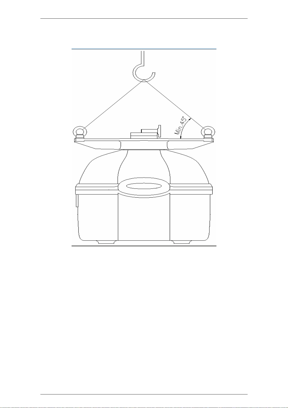
SRT X-BAND RADAR SYSTEMS
INSTALLATION
Fig 1 Lifting by crane
WARNING Never pass or stay under any lifted object.
304202P003 8.13 Rev. C
Page 97
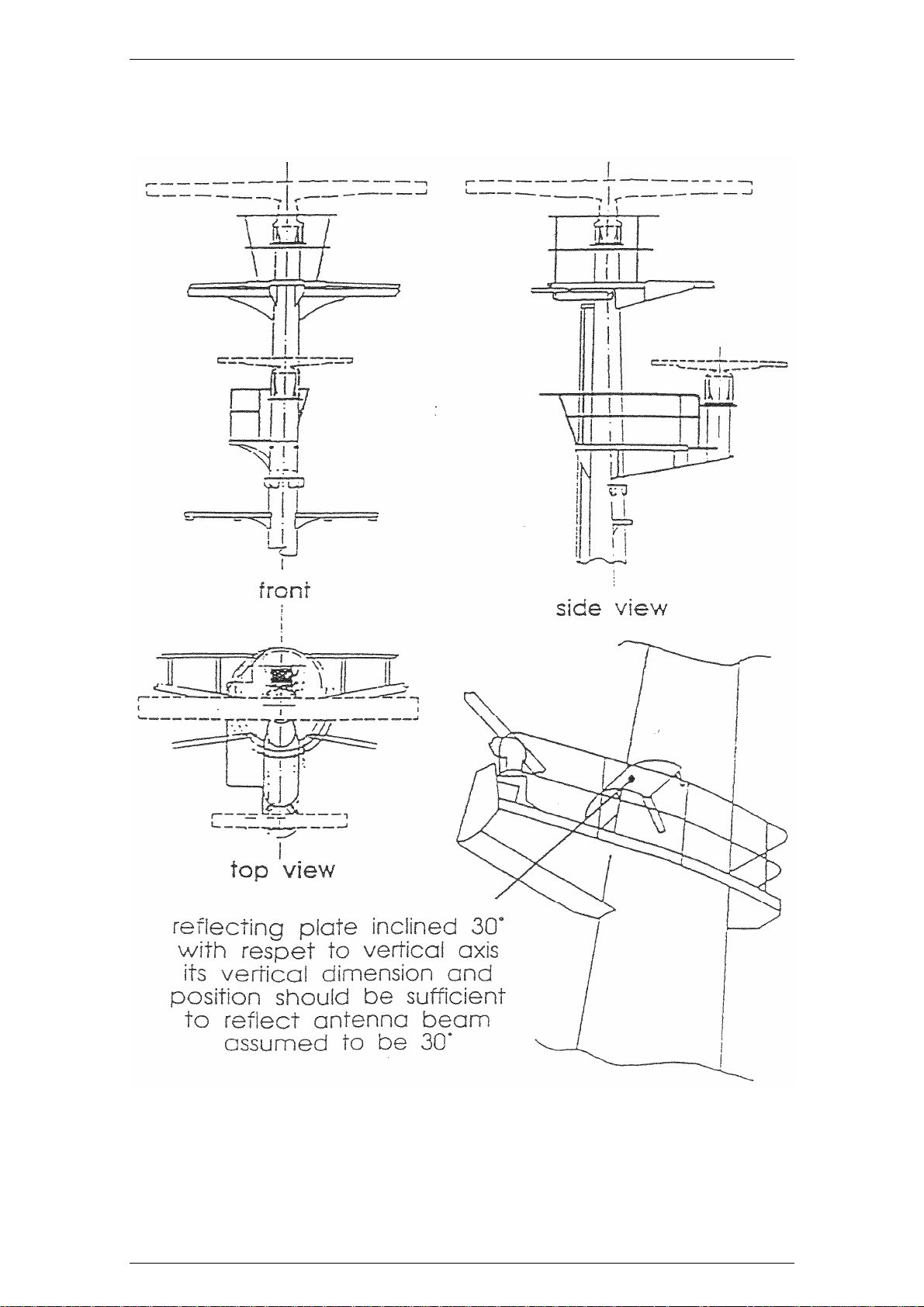
SRT X-BAND RADAR SYSTEMS
INSTALLATION
Fig 2 Suggested Masthead Antenna mounting
304202P003 8.14 Rev. C
Page 98
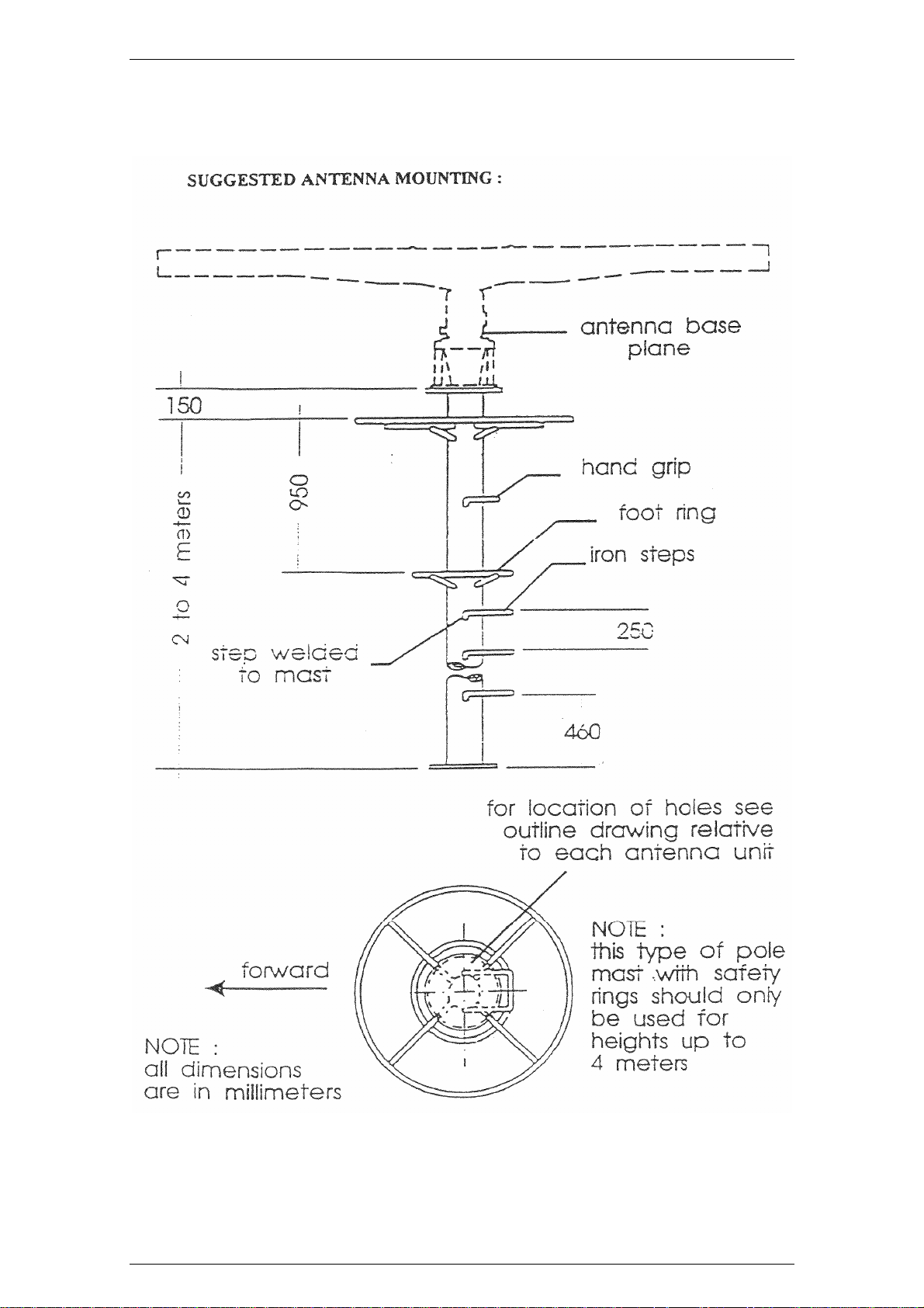
SRT X-BAND RADAR SYSTEMS
INSTALLATION
Fig 3 Suggested Antenna mounting
304202P003 8.15 Rev. C
Page 99
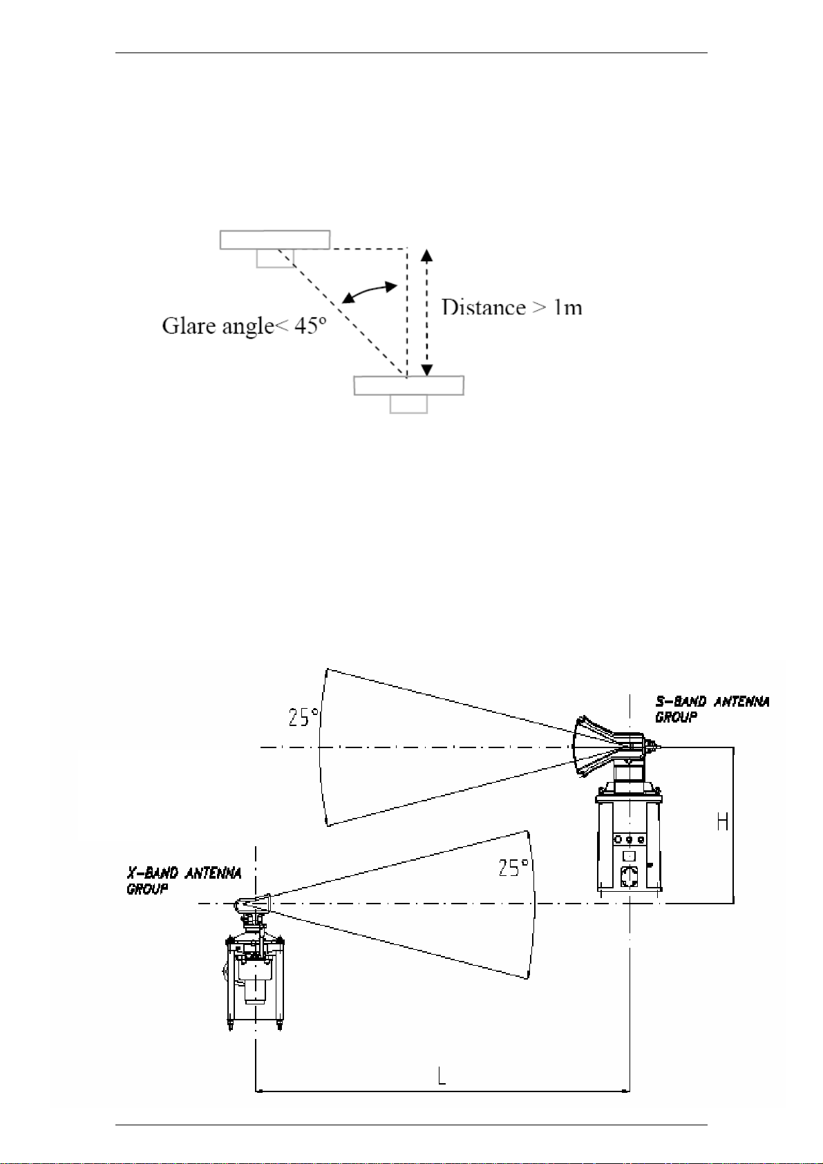
SRT X-BAND RADAR SYSTEMS
INSTALLATION
Fig 4 Antenna Positions
H ≥ L
304202P003 8.16 Rev. C
Page 100
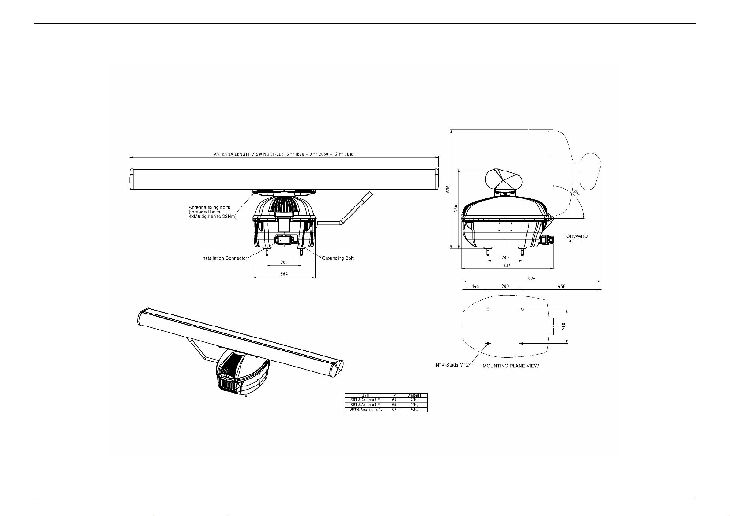
SRT X-BAND RADAR SYSTEMS
INSTALLATION
Fig 5 Dimension drawing
304202P003 8.17 Rev. C
 Loading...