

Consilium SELUX ST Installation And Service Manual

304648P001
Rev. E
September. 2010
SELUX ST INSTALLA-
TION AND SERVICE
MANUAL

CONSILIUM SELESMAR s.r.l.
Head Office & Plant
Via Romita, 26 - 50020 Montagnana V. P. (Florence) Italy
Tel.: +39/0571/68121 Telefax +39/0571/670798
304648P001
Rev. E
September 2010
SELUX ST INSTALLATION AND
SERVICE MANUAL

Selux ST Installation and service manual
A Rev. E
This page is intentionally left blank

Selux ST Installation and service manual
A Rev. E
APPLICATION FOR MANUAL REVISIONS
Upon receipt of this manual, please fill in the necessary data. It is
important that the addressee be the end user so that the operating
personnel will receive all revisions to the manual
EQUIPMENT NAME .............................................................................................
SERIAL No ..................................... MODEL ......................................................
MANUAL TITLE ....................................................................................................
........................................................ MANUAL PART NUMBER .........................
ISSUED INDEX ............................... REVISION INDEX ......................................
PURCHASING AGENCY ......................................................................................
NAME OF USER ...................................................................................................
ADDRESS OF USER ............................................................................................
.............................................................................................................
.............................................................................................................
ATTN: ..................................................................................................

Selux ST Installation and service manual
B Rev. E
RECORD OF CHANGES
RCS CODE/REV. INDEX
DATE PURPOSE OF THE
CHANGE
CHANGE
REQUESTED BY
Revision A June 2009 First issue N/A
Revision B December
2009
General revision N/A
Revision D April 2010 General revision N/A
Revision E
September
2010
General revision
N/A

Selux ST Installation and service manual
C Rev. E
MANUAL TABLE OF CONTENTS
Warnings
Chapter 1 INSTALLATION AND SETTINGS
Chapter 2 SERIAL INTERFACE SPECIFICATIONS
Chapter 3 RADAR CONFIGURATION
Chapter 4 DEBUG AND SIMULATION FACILITIES
Chapter 5 TROUBLESHOTTING
Chapter 6 Annex A
Chapter 7 Annex B
Chapter 8 Annex c

Selux ST Installation and service manual
D Rev. E
This page is intentionally left blank

Selux ST Installation and service manual
i Rev. E
TABLE OF CONTENTS
CHAPTER 1 Installation and setting ....................................................................... 1.1
1.1
G
UIDELINES FOR THE INSTALLATION OF SHIPBORNE RADAR EQUIPMENT
............... 1.1
1.2
I
NTERFERENCE
.......................................................................................................... 1.1
1.2.1
L
OCATION RELATIVE TO MASTS, FUNNELS AND OTHER CONSTRUCTIONS
............... 1.2
1.2.2
B
LIND SECTORS AND RANGE
..................................................................................... 1.2
1.2.3
I
NTERACTION WITH SEA AND FALSE ECHOES
........................................................... 1.4
1.2.4
C
ABLES AND GROUNDING
.......................................................................................... 1.4
1.2.5
R
ADAR CONTROLS CONTROLS AND DISPLAY
............................................................ 1.5
1.3
S
YSTEM SPECIFICATIONS
.......................................................................................... 1.6
1.3.1
D
IMENSION AND WEIGHT
........................................................................................... 1.6
1.3.2
P
OWER
....................................................................................................................... 1.6
1.3.3
E
NVIRONMENTAL DATA
.............................................................................................. 1.7
1.4
I
NPUT/OUTPUT REQUIREMENTS
................................................................................ 1.7
1.5
A
NALOGUE GYROCOMPASS (SYNCHRO OR STEPPER
) ........................................... 1.9
1.6
S
ERIAL GYRO
........................................................................................................... 1.11
1.7
S
PEED
LOG .............................................................................................................. 1.11
1.8
EPFS ........................................................................................................................ 1.12
1.9
AIS ............................................................................................................................ 1.12
1.10
VDR C
ONNECTION
................................................................................................... 1.13
1.11
R
ADAR CONSOLE FAILURE OUTPUT
........................................................................ 1.14
1.12
C
ONFIGURATION LINKS TABLE
................................................................................ 1.15
1.12.1
A
NTARES
PCB L
INKS
: .............................................................................................. 1.15
1.12.2
A
LPHA
PCB L
INKS
: ................................................................................................... 1.15
1.12.3
A
LPHA EXPANSION
PCB L
INKS
: ............................................................................... 1.17
CHAPTER 2 SERIAL INTERFACE SPECIFICATIONS ............................................. 2.1
2.1
S
ERIAL LINE
1 ............................................................................................................. 2.1
2.2
S
ERIAL LINE
2 ............................................................................................................. 2.3
2.3
S
ERIAL LINE
3 ........................................................................................................... 2.10
2.4
S
ERIAL LINE
4 ........................................................................................................... 2.30
2.5
S
ERIAL LINE
5 ........................................................................................................... 2.33
2.6
S
ERIAL LINE
6 ........................................................................................................... 2.34
2.7
S
ERIAL LINE
7 ........................................................................................................... 2.35
CHAPTER 3 RADAR CONFIGURATION .................................................................. 3.1
3.1
H
OW TO ACCESS THE RADAR CONFIGURATION
....................................................... 3.1
3.1.1
R
ADAR CONFIGURATION
............................................................................................ 3.1
3.2
G
YROCOMPASS CONFIGURATION
............................................................................. 3.3
3.3
S
PEED
LOG C
ONFIGURATION
.................................................................................... 3.5
3.4
O
WN SHIP DIM. AND WEIGHT
.................................................................................... 3.6
3.5
C
ONNING AND
EPFS POS. C
ONFIGURATION MENU
.................................................. 3.7
3.6
U
NCONVENTIONAL SENSOR CFG
............................................................................... 3.8
3.7
A
NTENNA SETTINGS
................................................................................................... 3.9
3.7.1
A
DJUSTMENT OF AZIMUTH TYPE
(PPR S
ELECTION
) ............................................... 3.10
3.7.2
A
DJUSTMENT OF THE HEADING LINE
....................................................................... 3.11
3.8
TXRX S
ETTINGS
....................................................................................................... 3.12
3.8.1
T
RANSCEIVER COMMUNICATION TYPE
.................................................................... 3.13
3.8.2
T
RANSCEIVER COMMUNICATION TYPE
.................................................................... 3.14
3.8.3
P
ERFORMANCE MONITOR ADJUSTMENT
................................................................. 3.15
3.8.4
T
UNING ADJUSTMENT
.............................................................................................. 3.15
3.8.5
M
AGNETRON TIMER RESET
...................................................................................... 3.16
3.8.6
D
IGITAL POTENTIOMETERS RESET
.......................................................................... 3.16
3.9
V
IDEO TRIGGER ADJUSTMENTS
.............................................................................. 3.17
3.9.1
T
RIGGER DELAY
....................................................................................................... 3.18

Selux ST Installation and service manual
ii Rev. E
3.9.2
QV (Q
UANTIZED VIDEO)THRESHOLD
....................................................................... 3.19
3.10
S
ECTOR BLANKING
................................................................................................... 3.19
3.11
S
YSTEM CONFIGURATION
........................................................................................ 3.21
3.11.1
D
ISPLAY RESOLUTION (FIG
3.11.1 -A) .................................................................... 3.21
3.11.2
IP A
DDRESS (FIG
3.11.1 -B) .................................................................................... 3.23
3.11.3
MAC A
DDRESS (FIG
3.11.1 -C) ............................................................................... 3.24
3.11.4
TXRX A
SSOCIATED BY DEFAULT (FIG
3.11.1 – D) .................................................. 3.24
3.11.5
G
ENERAL INFO(FIG
3.11.1 – E) ................................................................................ 3.24
3.11.6
A
DDITIONAL FUNCTIONS (FIG
3.11.1 – F) ................................................................ 3.25
3.12
R
ESTART BUTTON
.................................................................................................... 3.26
3.13
USB M
ENU (FIG
3.1.2-N) .......................................................................................... 3.27
3.13.1
S
AVE SCREENSHOTS
............................................................................................... 3.29
3.13.2
S
AVING AND RELOADING MAPS
............................................................................... 3.30
3.13.3
F
ILE CONFIGURATION
.............................................................................................. 3.30
3.13.4
S
YSTEM LOG FILES
................................................................................................... 3.30
3.14
P
ARAMETERS STORED ON BOARD
........................................................................... 3.31
3.15
S
OFTWARE UPGRADE
.............................................................................................. 3.32
CHAPTER 4 DEBUG AND SIMULATION FACILITIES ............................................. 4.1
4.1
G
ENERAL INFORMATION
............................................................................................ 4.1
CHAPTER 5 TROUBLESHOOTING .......................................................................... 5.1
5.1
I
NTRODUCTION
........................................................................................................... 5.1
5.1.1
S
AFETY PRECAUTIONS
.............................................................................................. 5.1
5.1.2
P
ERSONNEL
................................................................................................................ 5.1
5.2
R
EQUIRED TOOLS AND INSTRUMENTS
...................................................................... 5.1
5.3
C
ORRECTIVE MAINTENANCE PROCEDURES
............................................................. 5.2
5.4
C
ORRECTIVE MAINTENANCE PROCEDURES ON
DISPLAY CORE U
NIT
................... 5.3
5.4.1
DISPLAY CORE UNIT C
OVER REMOVING AND INSTALLATION
................................. 5.3
5.4.2
A
LPHA EXPANSION BOARD REPLACEMENT (OPTIONAL
) ........................................... 5.3
5.4.3
ANTARES A
SSY REPLACEMENT
................................................................................ 5.4
5.4.4
A
LPHA BOARD REPLACEMENT
................................................................................... 5.4
5.4.5
L
INE FILTER REPLACEMENT
....................................................................................... 5.5
5.4.6
P.S. A
SSY REPLACEMENT
.......................................................................................... 5.5
5.4.7
F
ANS ASSY REPLACEMENT
........................................................................................ 5.6
5.5
C
ORRECTIVE MAINTENANCE PROCEDURES ON THE MONITOR UNIT
..................... 5.13
5.6
C
ORRECTIVE MAINTENANCE PROCEDURES ON THE MONITOR UNIT
..................... 5.13
5.6.1
K
EYBOARD UNIT COVER REMOVING AND INSTALLATION
....................................... 5.13
5.6.2
KEYNT_2K B
OARD REPLACEMENT
......................................................................... 5.13
5.6.3
T
RACK BALL REPLACEMENT
.................................................................................... 5.14
5.6.4
K
EYBOARD PANEL REPLACEMENT
.......................................................................... 5.14
5.7
C
ORRECTIVE MAINTENANCE PROCEDURES ON THE
STANDARD
K
EYBOARD UNIT
5.16
5.7.1
K
EYBOARD UNIT COVER REMOVING AND INSTALLATION
....................................... 5.16
5.7.2
KEYNT_2K B
OARD REPLACEMENT
......................................................................... 5.16
5.7.3
T
RACK BALL REPLACEMENT
.................................................................................... 5.16
5.7.4
K
EYBOARD PANEL REPLACEMENT
.......................................................................... 5.16
5.8
I
NTRODUCTION
......................................................................................................... 5.16
5.8.1
P
ART LISTS
............................................................................................................... 5.17
5.8.2
P
ART LOCATION ILLUSTRATION
............................................................................... 5.17
5.8.3
P
ART LIST TABLES
................................................................................................... 5.17
5.9
S
YSTEM LIFETIME
..................................................................................................... 5.20
CHAPTER 6 Annex A ................................................................................................ 6.1
A
NTARES BOARD
...................................................................................................................................... 6.5
B
LOCK DIAGRAM DUAL
SELUX ST
WITH
SRT X-B
AND AND
RTM S-B
AND UP-MAST RADAR
S
ENSOR
..................................................................................................................................................... 6.6
B
LOCK DIAGRAM
SELUX ST WS-SRT UP MAST-SU UP MAST ............................................................. 6.7
B
LOCK DIAGRAM
SELUX ST
WITH
SRT UP-M
AST RADAR SENSOR
........................................................ 6.8

Selux ST Installation and service manual
iii Rev. E
B
LOCK DIAGRAM
SELUX ST WS - SU DOWN MAST .............................................................................. 6.9
B
LOCK DIAGRAM
SELUX ST
WITH
RTM S-B
AND UP-MAST RADAR SENSOR
....................................... 6.10
B
LOCK DIAGRAM
SELUX ST WS - SU UP MAST ................................................................................... 6.11
B
LOCK DIAGRAM DUAL
SELUX ST
WITH
SRT X-B
AND AND
RTM S B
AND DOWN-MAST RADAR
S
ENSOR
................................................................................................................................................... 6.12
B
LOCK DIAGRAM
SELUX ST WS - SRT DOWN MAST .......................................................................... 6.13
B
LOCK DIAGRAM
SELUX ST
WITH
SRT X-B
AND DOWN-MAST RADAR SENSOR
.................................. 6.14
B
LOCK DIAGRAM
SELUX ST WS-SRT DOWN MAST-SU DOWN MAST .............................................. 6.15
B
LOCK DIAGRAM
SELUX ST
WITH
RTM S-B
AND RADAR SENSOR
....................................................... 6.16
B
LOCK DIAGRAM
SELUX ST
WITH
RTM S-B
AND RADAR SENSOR
....................................................... 6.17
C
ONNECTION DIAGRAM
SELUX ST S
INGLE INSTALLATION
................................................................... 6.18
C
ONNECTION DIAGRAM
SELUX ST WS S
INGLE INSTALLATION
............................................................ 6.19
C
ONNECTION DIAGRAM
SELUX ST D
UAL INSTALLATION CONSOLE
(1) ................................................ 6.20
C
ONNECTION DIAGRAM
SELUX ST WS S
INGLE INSTALLATION CONSOLE
........................................... 6.21
C
ONNECTION DIAGRAM
SELUX ST D
UAL INSTALLATION CONSOLE
(2) ................................................ 6.22
C
ONNECTION DIAGRAM
SELUX ST WS
DUAL INSTALLATION
............................................................... 6.23
SELUX ST DISPLAY - M
ONITOR
T-340
OUTLINE DRAWING
.................................................................. 6.28
SELUX ST DISPLAY - M
ONITOR
T-250
DIMENSIONAL DRAWING
.......................................................... 6.29
SELUX ST DISPLAY - M
ONITOR
T-340 WS
DIMENSIONAL DRAWING
................................................... 6.30
SELUX ST DISPLAY – K
EYBOARD UNIT DIMENSIONAL DRAWING
........................................................ 6.31
SELUX ST DISPLAY – DISPLAY CORE UNIT
OUTLINE DRAWING
........................................................ 6.32
SELUX ST –WS DISPLAY – C
ABLES LENGTH
....................................................................................... 6.33
CHAPTER 7 Annex C ................................................................................................ 7.1

Selux ST Installation and service manual
iv Rev. E
This page is intentionally left blank

Selux ST Installation and service manual
v Rev. E
LIST OF TABLES
T
ABLE
1.4.1 - S
UMMARY OF THE INPUT/OUTPUT REQUIREMENTS
.......................................................... 1.7
T
ABLE
1.10.1 – VDR C
ONNECTION
......................................................................................................... 1.13
T
ABLE
1.10.2 – M
ONITOR TIMINGS
......................................................................................................... 1.14
T
ABLE
5.1 – L
IST OF CORRECTIVE MAINTENANCE PROCEDURES
.......................................................... 5.2

Selux ST Installation and service manual
1 Rev. E
WARNINGS
HIGH VOLTAGE
Radar equipment requires the use of high voltage, which can cause injury, or
loss of life. Danger exists only when the units are opened exposing internal
circuits, as when servicing the equipment. The Manufacturer Radar has been
carefully designed to protect personnel from possible injury from high voltages.
Nevertheless, it is recommended that the Line Switch always be opened as an
added protection when inspecting or servicing the equipment.
Although every effort has been made to eliminate danger to personnel, no
responsibility is accepted for any injury or loss of life suffered in connection with
this equipment.
X-RAY RADIATION
X-RAY radiation may be generated by Transceiver units and care must be
taken to avoid possible harmful effects when they are opened for maintenance.
When power is on, care should be taken not to approach closer than 1 ft. from
the unit unless front cover is in place.
RADIO-FREQUENCY RADIATION
Harmful effects (particularly to the eyes) may be caused by exposure of any
part of the human body to radio-frequency mean power densities in excess of
100 mW/cm2. This power density is exceeded at a distance of 1 ft. or less, from
the 12 ft. X-Band aerial (when stationary).
The system is however designed to disable radiation when the antenna is not
rotating.
The pedestals have also been predisposed for the installation of an external
safety switch, which can be mounted on, or near the platform. This switch
removes power from the Pedestal eliminating the possibility of accidental
operation during servicing and also causes disabling of transmission.
Whenever it is necessary to disconnect the waveguide system from a radar
transmitter for maintenance purpose, the transmitter output should, when
practicable, be terminated in a matched load. If this is not possible, care should
be taken to avoid standing in front of an open-ended waveguide from which
power is being radiated.
NEVER look down a waveguide from which power is being radiated.
SAFETY SWITCH
The Unit is provided of a safety switch, which disable the Antenna movement
during maintenance operations.

Selux ST Installation and service manual
2 Rev. E
SAFETY PRECAUTIONS
Purpose
The safety precautions described in this paragraph are applicable to Selux St.
Depending upon the material to be highlighted, the following attention letter
headings are used in the technical manual content.
WARNING
THIS IS OPERATING OR MAINTENANCE PROCEDURE,
PRACTICE, CONDITION AND STATEMENT WHICH. IF NOT
STRICTLY FOLLOWED, COULD RESULT IN INJURY TO OR
DEATH OF PERSONNEL
WARNING
THIS IS OPERATING OR MAINTENANCE PROCEDURE,
PRACTICE, CONDITION AND STATEMENT WHICH. IF NOT
STRICTLY OBSERVED, COULD RESULT IN DAMAGE TO,
OR DESTRUCTION OF, UNIT OR LOSS OF EMISSION
EFFECTIVENESS.
NOTE
An essential operating or maintenance procedure, condition or
statement which must be highlighted
Whenever a precaution, relating specifically to a part of the technical manual is
needed, the information is given in the relevant part of the manual. Warnings
and Cautions precede applicable text.
Safety Operations
During normal operation (front cover closed), the unit can be quickly
disconnected from the main power line, setting to OFF the relevant circuit
breaker located on the electric switchboard.
During maintenance (front cover opened) it is possible to turn-on the unit by
setting to SERVICE MODE the SW2 switch, mounted on the RTM Supply Assy.
This switch is connected in parallel with the relay, controlled by the POWER ON
command, and during normal operation must be set to NORMAL. During
maintenance, in order to prevent RTM occasional turning-on it is better to
disconnect and insulate, momentarily, PWON terminal from the relevant
terminal board.
NOTE
Main power line is always present on terminal board and on
fuses

Selux ST Installation and service manual
3 Rev. E
Safety Summary
The following are general safety precautions that are not related to any specific
procedure and therefore do not appear elsewhere in this technical manual.
These are recommended precautions that personnel must understand and
apply during most phases of operation and maintenance.
KEEP AWAY FROM LIVE CIRCUIT
Operating personnel must at all times observe all safety regulations.
Do not replace components or make adjustments inside the unit with the high
voltage supply turned ON. Under certain conditions, dangerous potentials may
exist when the power breaker is in the OFF position, also due to charges
retained by capacitors. To avoid casualties, always remove power and
discharge to ground a circuit before touching it.
DO NOT SERVICE OR ADJUST ALONE
Under no circumstances should any person initiate servicing or adjusting the
unit except in the presence of someone capable of helping help.
RESUSCITATION
Personnel working with or near high voltage should be familiar with modern
methods of resuscitation. Such information may be obtained from the Bureau of
Medicine and Surgery.
Warning Information
The following warnings appear in the text of this technical manual, and are
repeated here for emphasis.
WARNING
USE EXTREME CARE WHEN WORKING ON THE UNIT
ONCE THE COVER HAS BEEN OPENED. THE MAGNETRON
ASSEMBLY OPERATES AT VOLTAGES THAT MAY PROVE
FATAL
WARNING
BEWARE OF HIGH VOLTAGE CAPACITORS. IT IS
NECESSARY TO SHORT-CIRCUIT THEIR LEADS BEFORE
PERFORMING ANY MAINTENANCE ACTION ON THEM.
WARNING
ON THE ELECTRIC SWITCHBOARD, SET TO OFF THE
POWER BREAKER DEDICATED TO THE PRESENT
EQUIPMENT AND HANG TO IT A PLACARD READING:
“WORK IN PROGRESS-DO NOT SWITCH ON”

Selux ST Installation and service manual
4 Rev. E
WARNING
USE EXTREME CARE WHEN WORKING ON THE
EQUIPMENT ONCE THE FRONT COVER HAS BEEN
OPENED. THE MAGNETRON ASSEMBLY OPERATES AT
VOLTAGES THAT MAY PROVE FATAL
WARNING
SET MAIN LINE BREAKER TO OFF BEFORE REPLACING
ANY FUSE. FUSES ARE UNDER VOLTAGE LEVELS WHICH
MAY PROVE FATAL.

Selux ST Installation and service manual
5 Rev. E
This page is intentionally left blank

INSTALLATION AND SETTING
1.1 Rev. E
CHAPTER 1
INSTALLATION AND SETTING
1.1 Guidelines for the installation of
shipborne radar equipment
Information provided by radar is of vital importance for navigators and the safe
navigation of ships.
Special care should be taken to ensure the correct installation of the radar, in
order to improve the performance of the radar system.
Correct location of the radar antenna is an important factor of the performance
of the radar System. Interference, either by reflecting constructions or other
transmitters, may heavily reduce the radar performance by creating blind
sectors, clutter on the radar display or generation of false echoes.
1.2 Interference
Due care should be taken with regard to the location of radar antennas relative
to other antennas which may cause interference to either equipment. The
location of the antenna should comply with the following:
The radar antenna should be installed safely away from interfering high-power
energy
sources and other transmitting and receiving radio antennas.
The lower edge of a radar antenna should be a minimum of 500 mm above any
safety rail.
Radar antennas in dose proximity should have a minimum vertical elevation
separation angle of 20° and a minimum vertical separation of 1 m where
possible.
INSTALLATION AND SETTING
1.2 Rev. E
1.2.1 Location relative to masts, funnels and
other constructions
Due care should be taken with regard to the location of radar antennas relative
to masts, funnels and other constructions.
The location of the antenna should comply with the following:
The antenna should generally be mounted clear of any structure that may
cause signal reflections.
Ensure that any support or other obstacles are clear of the rotation of the
antenna (see specific antenna outline drawing for rotational radius).
Install antenna and turning unit so that the installation complies with the
compass safe distance for the equipment.
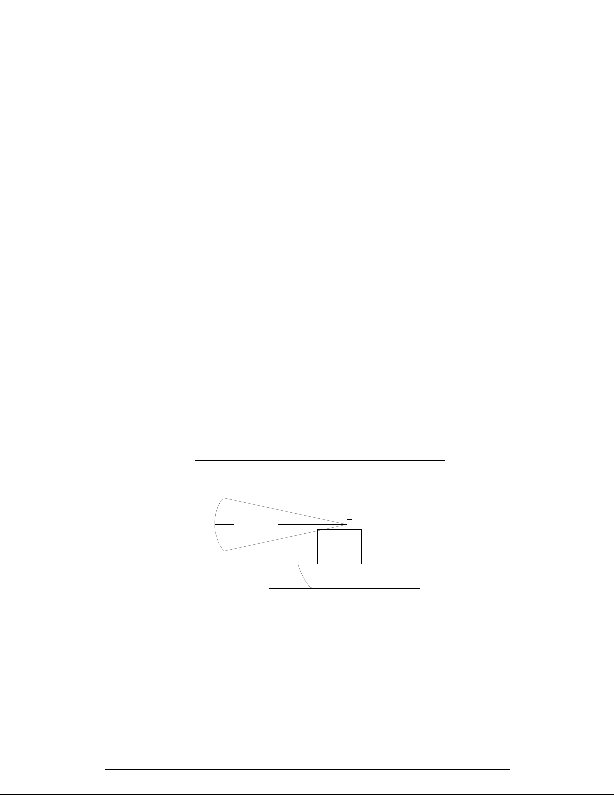
1.2.2 Blind sectors and range
To make full benefit from the radar, it is vitally important for the OOW that
horizontal and vertical blind sectors for the radar antennae are minimized. The
objective is to see the horizon freely through 360° as nearly as possible.
For all radar systems and where practical, a line of sight from the radar antenna
to the bow of the ship should hit the surface of the sea in not more than 500 m
or twice the ship length, depending which value is smaller, for all load and trim
conditions.
The radar antenna should be located in an elevated position to permit
maximum target visibility.
Waterline
Main Beam
13°
13°
Ideal Radiation Plane
INSTALLATION AND SETTING
1.3 Rev. E
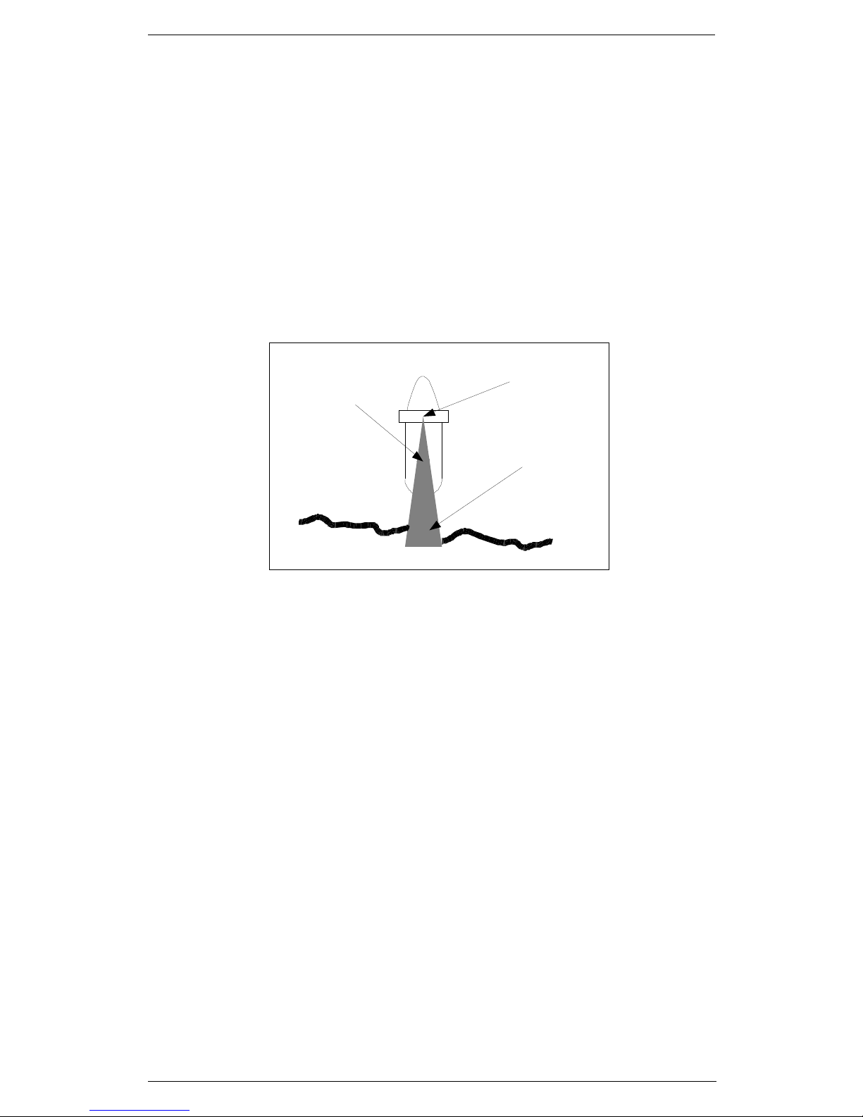
Blind sectors should be kept to a minimum, and should not occur in an area of
the horizon from right ahead to 22.5° abaft the beam to either side.
Note: Any two blind sectors separated by 3° or less should be treated as one
blind sector.
Individual blind sectors of more than 5°, or a total are of blind sectors of more
than 20°, should not occur in the remaining are, excluding the are
in the above subparagraph (e).
For radar installations with two radar systems, where possible, the antennas
should be placed in such a way as to minimize the blind sectors.
All installations should facilitate protection of equipment, including cabling, from
damage.
Safe service access should be provided using service platforms where
necessary having a minimum size of 1 m 2 at a suitable height and with a
safety rail of suitable height.
Consideration should be given to the compass safety distance as supplied by
the manufacturer when positioning equipment units.
The design of the mounting platform for the antenna and antenna pedestal
should take into account the vibration requirements of resolution A.694(17) and
furthermore defined by IEC 60945. In addition to vibration, the design of the
mounting platform should consider shock and whiplash due to seagoing
conditions.
Obstruction
(ex: funnel)
RAD AR Antenna
Blind Sector
Coastline

INSTALLATION AND SETTING
1.4 Rev. E
1.2.3 Interaction with sea and false echoes
Considerations of interaction with the sea imply that the radar antenna should
be only as high as necessary to clear major objects, and as high to be
consistent with other requirements regarding acceptable horizon and target
detection range. The location of the antenna should minimize sea clutter
returns and the-number of multi-path nulls.
1.2.4 Cables and grounding
The cables and the grounding should comply with the following:
Cable screens, especially coaxial cable screens, should be installed in
accordance with manufacturer's documentation.
The cables should be kept as short as possible to minimize attenuation of the
signal.
All cables between antenna and radar System units should be routed as directly
as possible, consistent with consideration for other equipment, in order to
reduce electromagnetic interference effects. Cables should not be installed
dose to high-power lines, such as radar or radio-transmitter lines.
Crossing of cables should be done at right angles (90°) to minimize magnetic
field coupling.
All outdoor installed connectors should be waterproof by design to protect
against water penetration into the cables.
Cables and microwave transmission lines should not be exposed to sharp
bends.
Cables and microwave transmission lines should be installed with sufficient
physical separation, as defined in the manufacturer's documentation.

INSTALLATION AND SETTING
1.5 Rev. E
1.2.5 Radar controls controls and display
If the control panel is a separate unit, the functionality of the radar controls
should be available for the mariner at all workstations where a radar display is
available.
The orientation of the display unit should be such that the user is looking
ahead. The lookout view should not be obscured and the ambient light should
cause minimum degradation on the display screen in accordance with
MSC/Circ.982.
WARNING
ONLY ELECTRONIC POSITIONING SYSTEMS (EPFS) APPROVED IN
ACCORDANCE WITH THE REQUIREMENTS OF THE IMO IN
RESOLUTION MSC.112(73) SHALL BE CONNECTED TO THE SELUXST RADAR CONSOLE.
WARNING
LONG TRANSMISSION LINES, COAXIAL CABLES FOR S-BAND AND
WAVEGUIDE FOR X-BAND DOWN MAST TRANSCEIVER CAN AFFECT
THE RADAR PERFORMANCE. THE SYSTEM HAS BEEN TESTED WITH
20M LENGTH FROM TRANSCEIVER TO THE ANTENNA PEDESTAL,
CONSIDER THAT TRANSMITTED/RECEIVED POWER ARE HALVED
FOR EVERY 10 MS ADDED (EX: +20M = -6DB SIGNAL/NOISE).
CLEARLY THIS AFFECTS DETECTION FOR FAR TARGETS AND FOR
SMALL/LOW REFLECTIVITY ONES LIKE SAIL SHIPS.
HIGHEST MAST POSITION IS GOOD FOR LONG RANGE DETECTION
BUT IT AFFECTS HEAVILY THE DETECTION IN SEA CLUTTER, FOR
OPTIMAL DETECTION IN SEA CLUTTER SUGGESTED ANTENNA
HEIGHT FROM SEA LEVEL IS AROUND 20M.
USUALLY THE CONTRADICTORY SPECIFICATIONS ARE SOLVED
WITH INSTALLATION OF MORE THAN ONE ANTENNA, FOR EXAMPLE
ONE AT 30M FOR LONG RANGE DETECTION AND ONE AT 20 M FOR
OPTIMAL DETECTION OF LOW INTENSITY ECHOES IN SEA
CLUTTER.
S-BAND TRANSCEIVER USE IS ALWAYS THE OPTIMAL CHOICE FOR
REDUCING RAIN CLUTTER REFLECTIONS AND INCREASE LONG
RANGE DETECTION LONGER ANTENNAS FOR X-BAND ARE LESS
SUSCEPTIBLE TO RAIN AND SEA CLUTTER.

INSTALLATION AND SETTING
1.6 Rev. E
WARNING
ACCORDING THE IMO STANDARD A GROUND SPEED SENSOR IS
REQUIRED TO BE CONNECTED TO THE SELUX ST CONSOLE.
IT IS ALLOWED TO USE AN ELECTRONIC POSITION FIXING SYSTEM
(EPFS) APPROVED IN ACCORDANCE WITH THE REQUIREMENTS OF
THE IMO IN RESOLUTION MSC.112(73) OR AN ALTERNATIVE TWO
DIMENSIONAL GROUND STABILISING SDME IN COMPLIANCE WITH
IMO RESOLUTION MSC.96(72)
WARNING
THE RADAR UNIT IS PROVIDED WITH A SAFETY SWITCH, WHICH
DISABLE THE ANTENNA MOVEMENT DURING MAINTENANCE
OPERATIONS AND AVOIDS HIGH VOLTAGE DAMAGE. ALWAYS TURN
THE SAFETY SWITCH OFF, WHENEVER ADVISED IN THIS MANUAL
(FOR INSTANCE, BEFORE PERFORMING ANY MAINTENANCE OR
INSTALLATION PROCEDURE). IGNORING SAFETY SWITCH
OPERATION MAY PRODUCE HAZARD OF ELECTROCUTION AS WELL
AS OTHER SEVERE INJURES
1.3 System Specifications
1.3.1 Dimension and Weight
See outline drawings
1.3.2 Power
Power supply
Single phase 220 or 115 Vac
+/- 15% 50/60 Hz
Power consumption
65 W
Monitor + DCORE + Expanded
Keyboard
INSTALLATION AND SETTING
1.7 Rev. E
1.3.3 Environmental Data
Operating temperature
-15°C / +55°C
Storage temperature
-25°C / +70°C
Relative humidity
Up to 95% at +40°
Water resistance, Salt spray, Vibrations
etc.
as per IEC 60945
1.4 Input/Output Requirements
The parameters with tolerances are included with each of the inputs listed.
Table 1.4.1 - Summary of the Input/Output Requirements
Feature Characteristics
Power
Voltage:
Consumption:
Single phase 110 to 230 Vac ±15%,
50/60 Hz ±6% 50 VA
Environmental
Conditions
Operating:
Storage:
Temperature -15°C to +55 °C
Temperature -20°C to +60 °C
Gyrocompass Synchro:
. Voltage value: 50 ÷ 115 Vac ±10%
(reference)
. 50/60 Hz or 300/400 Hz
. Gear ratio: 1:360, 1:180, 1: 90, 1:36
Stepper:
. Voltage value: 15 to +100 V positive
(Vef)
-15 to -100 V negative (Vef)
. Gear ratio: 1:360, 1:180, 1: 90, 1:36
Stepper rectified:
. Voltage value: 100 Vac (Vef)
. Frequency: 50/60 Hz or 300/400 Hz
±6%
. Gear ratio: 1:360, 1:180, 1: 90, 1:36
Serial:
. RS422 standard FNMEA or RS232
. Load: ≥ 7 KΩ, terminated 120 Ω
POS.
DESCRIPTION CODE
WIDTH
(mm)
HEIGHT
(mm)
DEPTH
(mm)
WEIGHT
(kg)
1 30 kW S-Band Receiver
Transmitter Modulator Up
and Down
09N-011 535 481 297
2 S Band Antenna Pedestal
Normal Speed
03R-039 660 650 430 115
3 12' S Band Antenna 02R-039/B Length 3662 (circle 3700) 80
4 Technical manual 303733P001

INSTALLATION AND SETTING
1.8 Rev. E
Feature Characteristics
Speed Log Mechanical input:
. PRR: 100 pulses/NM, 200
pulses/NM, 400 pulses/NM
. Input type: diode isolated, pull-up
. pulse width: 1 ms (min)
. Load: ≥ 2.7 KΩ
. Threshold: +10 V (typ)
Speed For
Electronic input
(switch):
. PRR: 120 pulses/m, 20000
pulses/NM
. Load: ≥ 1 KΩ
. Pulse width: 0.1 µs (min)
. Voltage: TTL to 15V (typ)
Speed Serial
Electronic input
(serial):
. Input type: RS422 standard NMEA or
RS 232
. Load: ≥ 3 KΩ, terminated 120 Ω
System Failure
(FAIL)
TB1 (pin 5-6)
Relay output NC
Closed when the system is in failure or
switched off
- Max 125 V 30 W load
Danger Target
(DGT)
TB1 (pin 3-4)
Relay output NC/NO
configurable
Active when a Radar Target or AIS is
dangerous
- - Max 125 V 30 W load
Dead Man Alarm
Reset (DNA)
TB1 (pin 1-2)
Relay output NC/NO
configurable
Active when an action is made on the
control panel
- Max 125 V 30 W load
Video and Combined data without
ALPHA Expansion or CH3 and CH4
with this card
. Voltage value: 0,8 to 1,5 Vpp adjustable
. Load: ≥ 1 KΩ, terminated 75 Ω
Video and data with Alpha Expansion CH1 and CH2: (Optional)
Video:
Polarity: . Positive or negative
Amplitude: . 1 to 4 Vpp adjustable
Load: . Load: ≥ 1 KΩ, terminated 75 Ω
Bandwidth: . 24 MHz (-3 dB)
Trigger: Polarity: . Positive or negative
Amplitude: . TTL to 40 V (peak)
Load: . Load: ≥ 1 KΩ, terminated 75 Ω
PRF: . 300 to 4000 Hz
Pulse width: . 50 ns (min.)
Serial Interface: Signal Standard:
. RS232 or RS422
. Load: ≥ 3 KΩ, terminated 120 Ω
Antenna Rotation Rotation rate: . 15 to 60 RPM
Data Device type:
- Bearing
. Voltage value: 4 to 50 V
. 128 or 132 pulses per antenna
revolution
. Load: ≥ 2 KΩ
- Encoder
. Voltage value: 4 to 50 V
. 1024 or 4096 pulses per antenna
revolution
. Load: ≥ 2 KΩ
Heading line Voltage value: . 4 to 50 V
Load: . Load: ≥ 2 KΩ
Pulse width: . ≥ 0,1 mS and < 45°
Polarity: . Positive or negative or bipolar
INSTALLATION AND SETTING
1.9 Rev. E
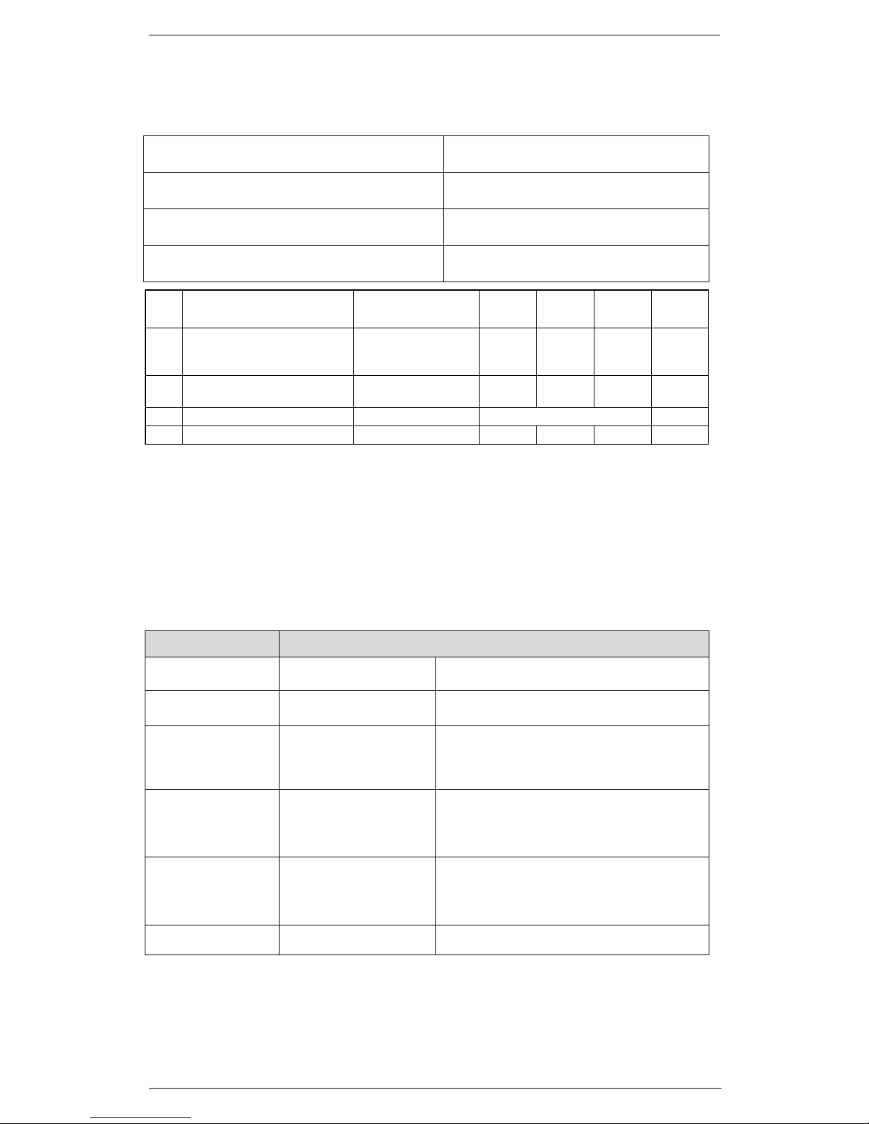
1.5 Analogue Gyrocompass (Synchro or
Stepper)
The gyro signals are connected to TB14 on the Alpha PCB. There are several
possibilities of connections depending on the type and reference voltage of the
gyro.
Refer to the drawing below for the relevant configuration for Synchro and
Stepper.
Fig 1 For Selux (ALPHA PCB) connect to TB14.
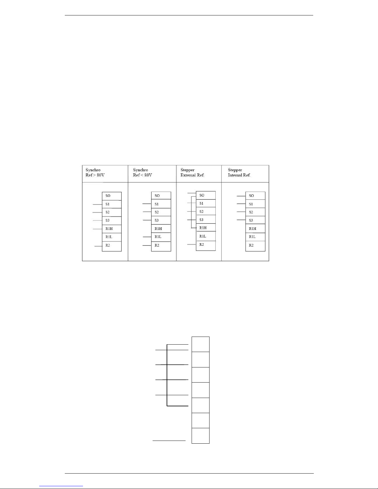
Note: Connection with stepper gyro full wave rectified signal (SPERRY MK-37,
MK-20)
1. Close the jumpers P10, P13, P15 on the Alpha PCB;
2. make the interconnection to TB4 on the Alpha PCB as follow:
TB14
WIRE
NUMBERS
FROM
GYRO
S0
S1
S2
S3
R1H
R1L
R2
#5
#1
#2
#3
#4

INSTALLATION AND SETTING
1.10 Rev. E
3. Follow the configuration instructions described in Chapter 3
4. Check the phases status trough the LED on the Alpha PCB.
The three phases are given by the gyro with a 3 bit Gray code. The purpose of
this code is to detect the increment of the value and its sign; its most important
characteristic is that only one of the three bits at the time can change and in
this application (normally is not a characteristic of the Gray code), the 3 bits
cannot have all the same level. To give a quick look to the Gray code see the
four green LED on the Alpha:
1. The first one next to red LED is D33 and it indicates the first phase (S1).
2. The second one is D34 and it is the second phase indicator (S2).
3. The third one is D35 and it indicates the third phase (S3).
4. The last one is D36 and it is to indicate the Reference.
Now that the LED are individuated move the gyro or anyway simulate a steering
and the three LEDs (S1, S2 and S3) will start to change their state and will be
easy to observe that they will be never all on or all off and only one of them at
the time will change its state.
WARNING
THE GYRO INTERFACE SHOULD BE CONFIGURED CORRECTLY
ACCORDING TO TYPE OF SENSOR CONNECTED, OTHERWISE
LEVELS AND LED SIGNALS WILL BE LIGHTED WRONGLY ALSO
WHEN THE SIGNALS ARE AVAILABLE.
S1
S3 S2
Gyro Phases combinations in Gray
INSTALLATION AND SETTING
1.11 Rev. E
1.6 Serial Gyro
A Standard or Fast NMEA Gyro can be connected on Alpha PCB TB9
Connect it according the guidelines defined in Chapter 2 Serial Interfaces.
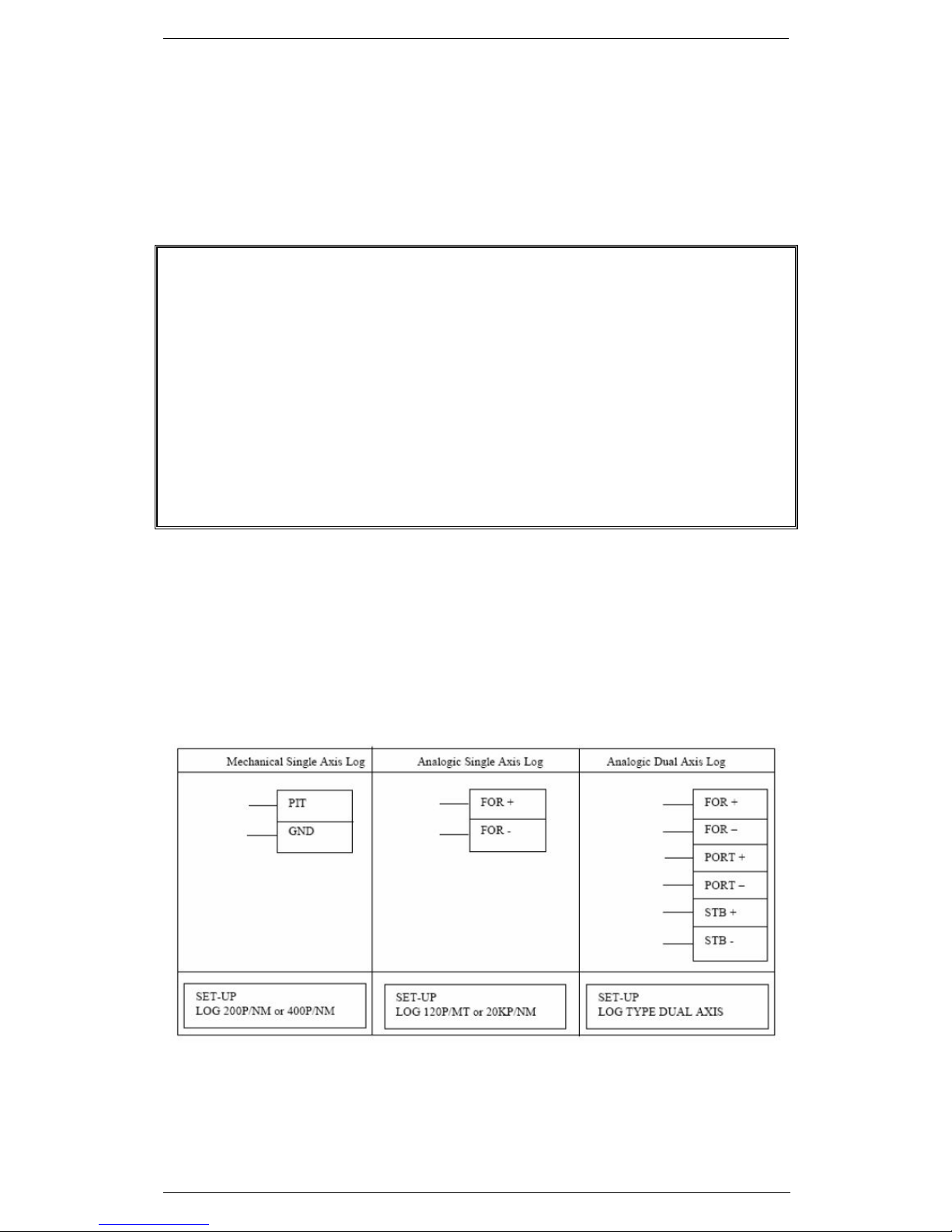
1.7 Speed LOG
In case of analogue signal the speed log is connected to TB14 on the Alpha
PCB. There are several connections depending on the type of log installed.
Most of the single axis analogue speed logs are shorting-type (relays contact),
in this case the signal shall be connected between PIT and GND on TB14.
In case of NMEA signal the speed log also can be connected to Alpha PCB
input TB2.See the serial interface chapter for accepted sentences.
WARNING
THE HEADING SENSOR, A GYRO EQUIPMENT OR EQUIVALENT, SHOULD
BE ABLE TO SUSTAIN A RATE OF TURN UP TO 20°/S ACCORDING TO
IMO RESOLUTION MSC.192(79) AND MSC.116(73) FOR THD DEVICES.
IF THE INTERFACE IS ANALOGUE THE MINIMUM TURN RATE SHOULD
BE 12°/S.
FOR A DIGITAL INTERFACE THE HEADING REFRESH SHOULD BE MORE
THAN 20HZ, UP TO 50HZ.
IF THE GYRO UPDATE RATE IS UNDER THE PREVIOUS STATED VALUES
THE TRACKING PERFORMANCE CAN BE SERIOUSLY DEGRADED WITH
INCREASING ERRORS ON TARGET VECTOR DURING THE OWN SHIP
CHANGE OF COURSE.

INSTALLATION AND SETTING
1.12 Rev. E
1.8 EPFS
The EPFS (Electronic Position Fixing System) signal is connected to TB3 on
the Alpha PCB.
In case of Selux-ST system communicating to an INS or ECDIS also the Output
of this serial line sends some data and it shall be connected.
NOTE
Supported EPFS equipment must follow the IMO
recommendation MSC.114(73)
1.9 AIS
The AIS signal is connected to TB8 on the Alpha PCB.
It's possible to receive RS422 or RS232 standard signal only at 38400 bps. The
sentences accepted are: AIALR, AIVDM and AIVDO.
NOTE
it is also possible to connect the output from the RADAR to the
AIS device, to acknowledge the alarms coming from AIS from
the RADAR interface. Normally the AIS equipments have only
one input available, so that only one RADAR can be connected
to it and it will be only one able to acknowledge the alarms.
This output is on the same serial port TB8 with only sentence
generated: AIACK
The same output, is the source for tracking data sentences TTD and TLB.
NOTE
Supported AIS equipment must follow the IMO
recommendation A.917(22)
INSTALLATION AND SETTING
1.13 Rev. E
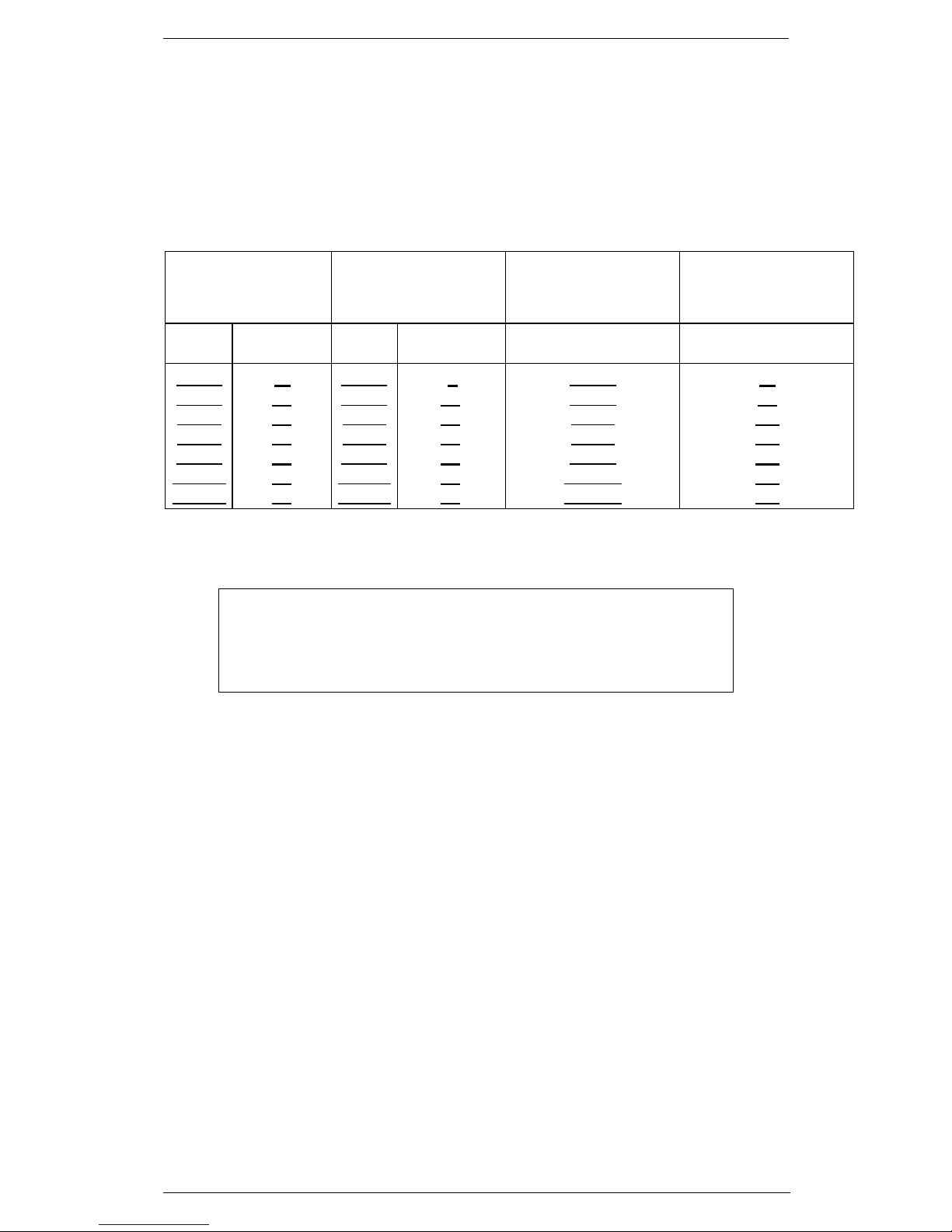
1.10 VDR Connection
To connect a VDR System to the Selux-ST Radar use the VGA Output on the
Alpha Assy. The maximum distance from the Unit to the VDR depends on the
resolution of the Video signal output of the cable in use. See the following table
for distances in function of cable type.
Video
1280x1024
Video
1600x1200
Video1680x105
(20’’ wide screen)
Video1680x105
(26’’ wide screen)
Cable
Distance
(m)
Cable
Distance
(m)
Cable
Distance
(m)
RG75
RG59
M202
M203
RG11
CT100
CT125
10
25
25
35
40
50
60
RG75
RG59
M202
M203
RG11
CT100
CT125
8
20
20
30
30
40
45
RG75
RG59
M202
M203
RG11
CT100
CT125
10
25
25
35
40
50
60
Table 1.10.1 – VDR Connection
NOTE
- Supported VDR equipment must follow the IMO
recommendation A.861(20)
- The VDR outlet is completely different from the DVI outlet to
which the monitor is connected
 Loading...