

Consilium Salwico CS3000 Service Manual

Fire Alarm System
Salwico CS3000
Service manual
Ver. 6
çConsilium

The contents of this document are subject to revision without notice due to continued progress in
methodology, design and manufacturing. Consilium assumes no legal responsibility for any error
or damage resulting from the usage of this document.
Edition 5, 09 1 E, August 2009.
Document no. S-4-007.875
Part no: 070073
© 2004-2009, Consilium Fire & Gas AB
Consilium Marine AB
P.O. Box 8763
SE-402 76 GÖTEBORG
SWEDEN
Tel: +46-31-710 77 00, Fax: +46-31-710 78 00
E-mail: cmab.got@consilium.se
Internet: www.consilium.se

Service Manual CS3000 Contents i
Document no.: S-4-007.875/E
Prepared: 1995-03-17 Fia
Revision: R4 2004-03-15 BM
© 1995, Consilium Marine AB
Contents
About this manual..................................................................................................... ii
Chapter 1: Control unit
Service mode............................................................................. 1-1
Set address........................................................................ 1-1
Bypass built-in short circuit isolators................................... 1-1
Chapter 2: The circuit board of the control unit
Input/Output board IKK-4................................................. 2-1
Chapter 3: The circuit boards of the central unit
Loop processor board SPK-2............................................... 3-01
Alarm processor board LPK-2.............................................. 3-09
Relay board ARK-2.................................................................. 3-13
Input board INK-2..................................................................... 3-18
Output board UTK-2
................................................................ 3-22
Interface board GSK
-2.............................................................3-26
Interface board RS232K-2..................................................... 3-30
Interface board KPK-2............................................................ 3-34
Rack CSR-3200........................................................................ 3-38
Power unit CSS-3300............................................................. 3-40
Appendix A. DIP switch settings............................................................... A-1
Appendix B. Fault codes CS3000 version 4...................................... B-1
Appendix C. Fault codes CS3000 version 6..................................... C-1

Service Manual CS3000 Contents ii
Document no.: S-4-007.875/E
Prepared: 1995-03-17 Fia
Revision: R4 2004-03-15 BM
© 1995, Consilium Marine AB
About this manual
This manual is intended to be used by personnel who maintain and perform
service on the CS3000 system.
Chapter Control Unit gives a general description on how the Control unit
works.
Chapter The Circuit Board of the Control Unit describes the functions of the
Control unit’s circuit board.
For information regarding the Central unit’s various circuit boards refer to The
Circuit Boards of the Central Unit chapter.
DIP switch settings for all different parts of the CS3000 system are listed in
the DIP Switch Settings appendix.
The fault codes for CS3000 version 4 and 6 are listed in the Fault Codes
CS3000 Version 4 and Fault Codes CS3000 Version 6 appendixes
respectively.
For a more detailed description of the system refer to the CS3000 Reference
Manual.

Service Manual CS3000 Chapter 1: Service mode 1-1
Control unit
Document no.: S-4-007.875/E
Prepared: 1995-03-17 Fia
Revision: R4 2004-03-15 BM
© 1995, Consilium Marine AB
Chapter 1: Control unit
Service mode
The control unit includes a fourth access level to be used only by the service
engineer. There are two functions in the service mode: bypass the built-in short
circuit isolators and definition of control unit address.
Set address
(Access level 4)
Each control unit in the system must have a unique address in the interval 217
- 232. The control unit number must correspond with the number defined in
the Definition program. The control unit address must be set after the system
definition is downloaded and the system is restarted.
• Press F4 (MENU) until SERVICE is displayed on line 4.
• Press F1 (SERVICE).
• Press F1 (ADDRESS).
• Enter the address for the control unit. The address interval is 217 - 232.
Bypass built-in short circuit isolators
The built-in short circuit isolators, two on each loop, are bypassed when you
activate the SERVICE function. The short circuit isolators remain bypassed
until you activate them again.
• Press F4 (MENU) until SERVICE is displayed on line 4.
• Press F1 (SERVICE).
Service Manual CS3000 Chapter 2: Input/Output board IKK-4 2-1
The circuit board of the control unit
Document no.: S-4-007.875/E
Prepared: 1995-03-17 Fia
Revision: R4 2004-03-15 BM
© 1995, Consilium Marine AB
Chapter 2: The circuit board of the control unit
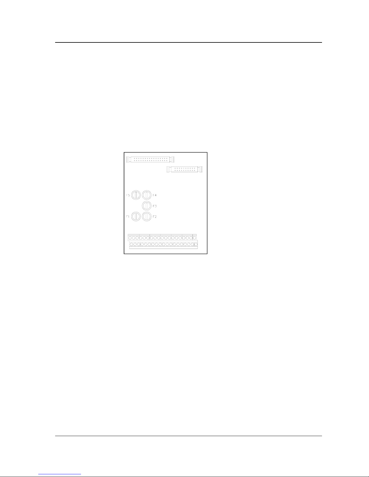
Input/Output board IKK-4
General
The Input/output board (IKK-4) interfaces the control unit processor board to
the system loop. The IKK-4 board also includes circuits for transient
suppression of all external signals. The IKK-4 board is controlled by the
control unit board, via the address and data busses.
Handling
Fuses
Fuse Fuse rating Fault code
F1: Control unit panel 500 mAT 5x20 mm Not supervised
F2: Main fuse 100 mAT 5x20 mm Not supervised
F3: Main fuse for F4-F5 500 mAT 5x20 mm Not supervised
F4: Power supply ext. device 315 mAT 5x20 mm Not supervised
F5: Power supply 315 mAT 5x20 mm Not supervised
Service Manual CS3000 Chapter 2: Input/Output board IKK-4 2-2
The circuit board of the control unit
Document no.: S-4-007.875/E
Prepared: 1995-03-17 Fia
Revision: R4 2004-03-15 BM
© 1995, Consilium Marine AB
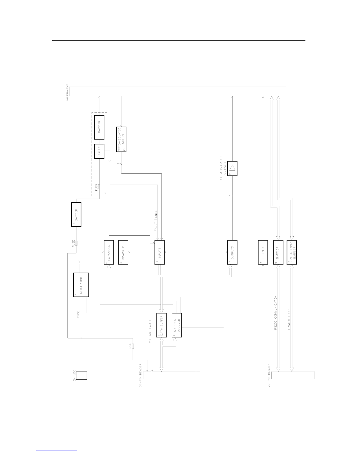
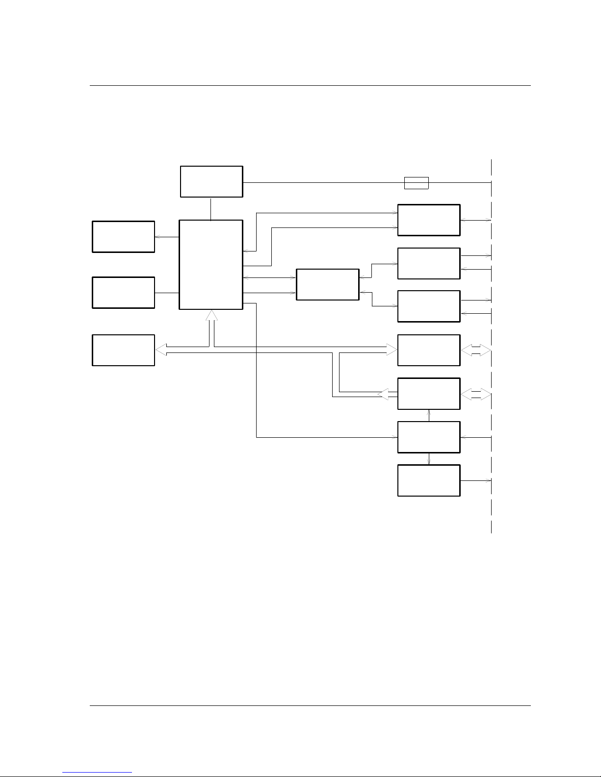
Function
Block diagram

Service Manual CS3000 Chapter 2: Input/Output board IKK-4 2-3
The circuit board of the control unit
Document no.: S-4-007.875/E
Prepared: 1995-03-17 Fia
Revision: R4 2004-03-15 BM
© 1995, Consilium Marine AB
1. Data buffer
The data bus is buffered before entering/leaving the board.
2. Address decoder
The address decoder selects the different blocks. The address decoder is
controlled by the control unit board.
3. Regulator
The regulator converts power voltage to 5 VDC.
4. Expansion
Future expansion possibilities. Not used.
5. Board ID
The control unit board reads the IKK-4 ID.
6. Inputs
Reads all external inputs.
7. Outputs
Controls the four transistor outputs.
8. Buzzer
An external buzzer may be connected via a transient protected output. The
buzzer will be parallel connected to the fire alarm and the fault buzzer on the
control unit board.
9. Barrier
The RS 232 communication is protected against transients before entering the
control unit board.
10. System loop barrier
Transient barrier for the system loop.
11. Barrier
The power supply voltage output is protected against external transients.
12. Power supply output
A fused and fault supervised output for power supply to an external device.
13. Opto-isolated inputs
Four opto-isolated transient protected external inputs.
14. Opto-isolated outputs
Four transistor outputs. Deactivated at hang-ups in the programme execution.

Service Manual CS3000 Chapter 2: Input/Output board IKK-4 2-4
The circuit board of the control unit
Document no.: S-4-007.875/E
Prepared: 1995-03-17 Fia
Revision: R4 2004-03-15 BM
© 1995, Consilium Marine AB
Technical data
Board size: 145 x 107 mm
Ambient temperature: -10°C - +70°C.
Ambient humidity: 96% Rh.
Input power: U
in
: 24 VDC (-20% - + 25%).
Current consumption: I
in nom
: 15 mA
I
in max
: 40 mA.
Outputs: 4 opto-isolated sourcing outputs
Inputs: 4 opto- isolated inputs, active high
Service manual CS3000 Chapter 3: Loop processor board SPK-2 3-1
The circuit boards of the central unit
Document no.: S-4-007.875/E
Prepared: 1995-03-17 Fia
Revision: R4 2004-03-15 BM
© 2002, Consilium Marine AB
Chapter 3: The circuit boards of the central unit
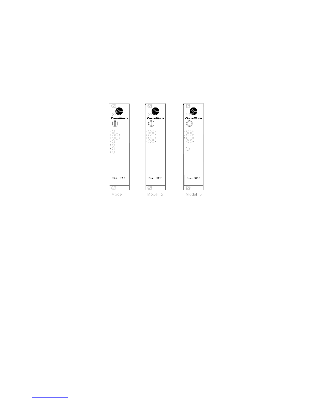
Loop processor board SPK-2
The loop processor boad SPK-2 exists in three different models. Model 1 and
model 2 differs only in the exterior of the front panel, whereas Model 3 has an own
block diagram.
General
The loop processor board SPK-2 controls and supervises two detector loops with
analogue and addressable detectors. The detectors are constantly polled in order to
detect faults or changes in alarm status. Detector-initiated alarms are also
recognised and verified. The events are reported to the LPK-2 and proper hardware
signals are then activated.
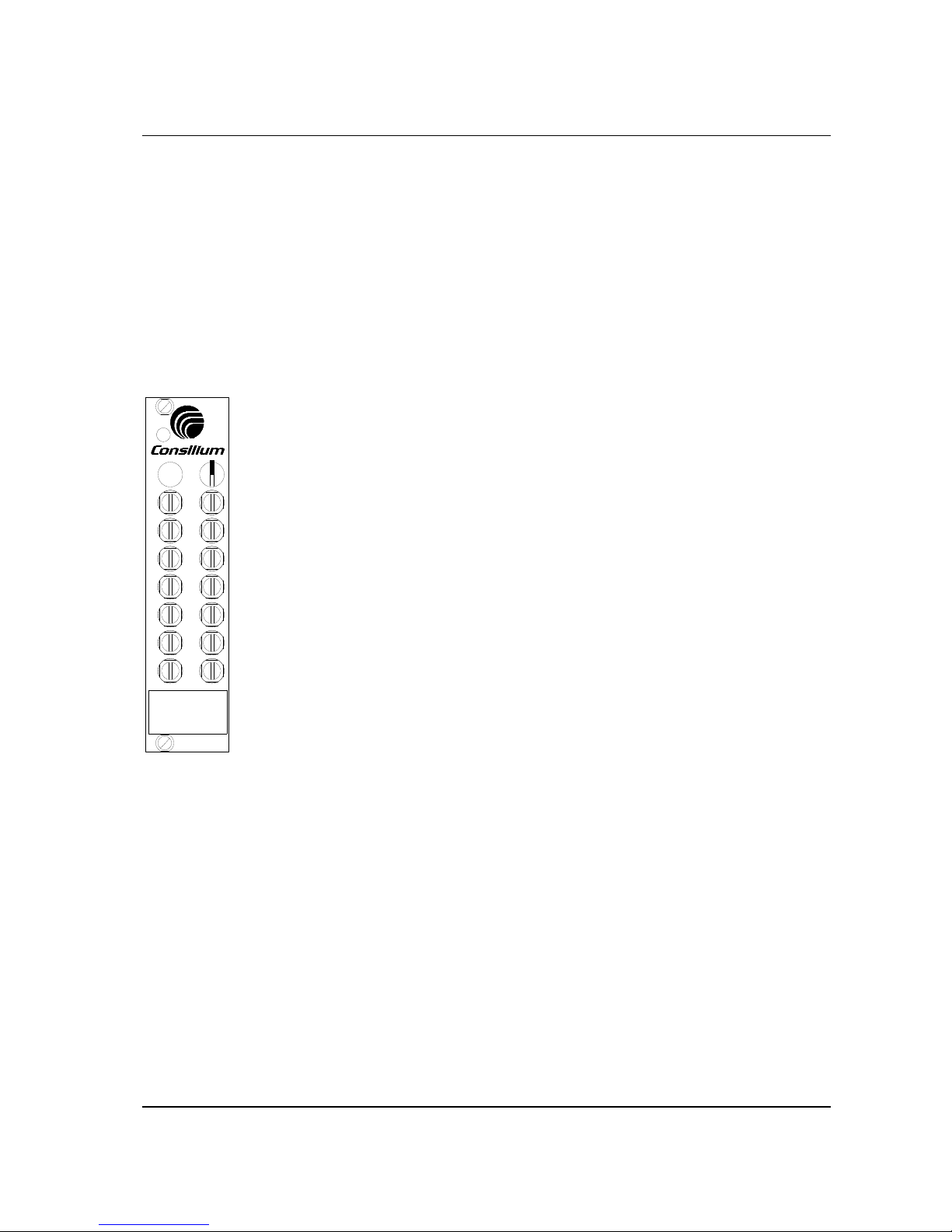
Handling
Indications
Model 1 There are nine LEDs on the front panel of the board.
No 1 (green) when lit: proper voltage supply.
No 2 (yellow) when lit: fault in loop #1.
No 3 (red) when lit: fire alarm in loop #1.
No 4 (yellow) when lit: fault in loop #2.
No 5 (red) when lit: fire alarm in loop #2.
No 6 (yellow) when lit: local processor failure
No 7 (in service mode) will flash synchronously with the central unit’s
communication with the loop-PCB.
No 8, 9 (in service mode) will flash synchronously with polling of the
loop-units
Model 2 & 3 There are eight LEDs on the front panel of the board.
No 1 (green) when lit: proper voltage supply.
No 2 (yellow) when lit: local processor failure.
No 3, 4 (green) (in service mode) will flash synchronously with polling of the
loop-units
No 5 (yellow) when lit: fault in loop #1.
No 6 (red) when lit: fire alarm in loop #1.
No 7 (yellow) when lit: fault in loop #2.
No 8 (red) when lit: fire alarm in loop #2.
Service manual CS3000 Chapter 3: Loop processor board SPK-2 3-2
The circuit boards of the central unit
Document no.: S-4-007.875/E
Prepared: 1995-03-17 Fia
Revision: R4 2004-03-15 BM
© 2002, Consilium Marine AB
Fuse
The battery voltage is fused. If the fuse is blown a signal is activated in the back
plane. The fuse is accessible on the front panel of the board, and can be used for
disconnecting the power.
Fuse ratings:
Model 1 & 2: 1 AT 5x20 mm
Model 3: 1.6 AT 5x20 mm
Setting the address
The address of loop #1 of the board is set with a DIP-switch (SW1), with 8
switches. Bit #1 is set with SW1-1, and bit #8 with SW1-8. The address of loop #2
is automatically set by the system to the next consecutive value.
Set the address of each SPK-2 according to the definition in the Definition
program.
Restarting the board
Remove the fuse from the board to disconnect the power. When the fuse is put back
on, the board is restarted.
Replacing the board
To replace the SPK-2 follow these steps:
1. Disconnect the power by removing the fuse.
WARNING!
The power must be disconnected before the board is removed.
2. Remove the board and replace it with the new board.
Service manual CS3000 Chapter 3: Loop processor board SPK-2 3-3
The circuit boards of the central unit
Document no.: S-4-007.875/E
Prepared: 1995-03-17 Fia
Revision: R4 2004-03-15 BM
© 2002, Consilium Marine AB
Function
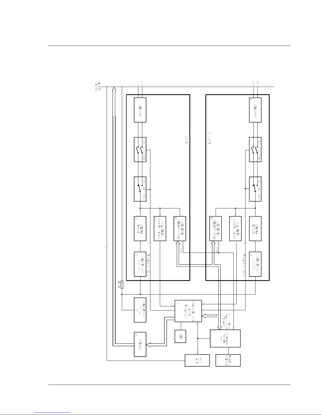
Block diagram Model 1 & Model 2
NB! In the diagram blocks 8 - 14 are doubled, one set for each detector loop.

Service manual CS3000 Chapter 3: Loop processor board SPK-2 3-4
The circuit boards of the central unit
Document no.: S-4-007.875/E
Prepared: 1995-03-17 Fia
Revision: R4 2004-03-15 BM
© 2002, Consilium Marine AB
1. Power supply
Power supply for processor, memory and logic of the loop processor board.
2. Control logic
Control logic for activation and blocking of hardware signals to the back plane.
LEDs for indication of status and communication are also controlled in this block.
3. LED indications
LEDs for indicating status of fire, fault, communication and voltage.
4. Drivers
Drivers for adapting hardware signal to the back plane.
5. CPU/Memory/watchdog
This is the main block of the SPK-2 board. The CPU controls both of the detector
loops and the communication with the LPK-2. The memory circuits contain the
programme code, default data for the detectors and status information. The
watchdog supervises the processor and checks for hang-ups in the programme
execution.
6. Address switch
The 8-bit address of the SPK-2, i.e. the loop number, is set with the DIP switch.
7. LPK communication
Interface for back plane communication.
8. DC/DC converter
The DC/DC-converter converts the battery voltage from the back plane to 30 VDC,
for the detector loops.
9. Signal filter
Signal filter for the communication signals.
10. Communication direction switch
For closed loops the choice of direction for the communication is made with this
switch.
11. Disconnection switch
With this switch the entire detector loop may be disconnected.
12. Barrier
Barrier for protecting the loops against incoming transients.
13. Basic-Alarm detection
Circuit for the detection of a basic-alarm.
14. Transmitter/receiver
Transmitter, receiver and interface for the processor bus.
15. Buses
The control signal bus contains signals to control the reading and writing of devices
connected to the address bus and the data bus.
Service manual CS3000 Chapter 3: Loop processor board SPK-2 3-5
The circuit boards of the central unit
Document no.: S-4-007.875/E
Prepared: 1995-03-17 Fia
Revision: R4 2004-03-15 BM
© 2002, Consilium Marine AB
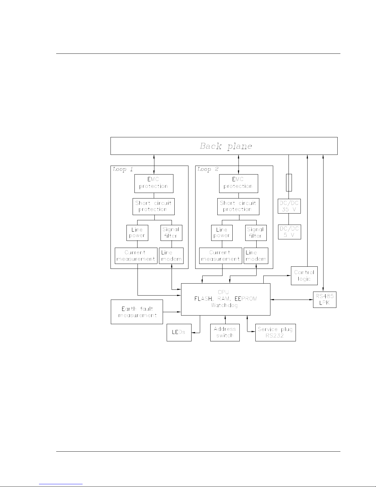
Block diagram Model 3
SPK-2 Model 3 can be split into three functions: Power supply, loop and processor
with memory. The power supply provides the board with loop power and power for
the logic and the processors. The loop part contains electronics for two loops and
handles power supply for the loop and sending/transmitting of IDA and NOSE
messages. The processor controls the loops and communicates with the LPK via the
RS485 channel of the back plane.
The whole board is galvanically isolated from the CS3000 rack.

Service manual CS3000 Chapter 3: Loop processor board SPK-2 3-6
The circuit boards of the central unit
Document no.: S-4-007.875/E
Prepared: 1995-03-17 Fia
Revision: R4 2004-03-15 BM
© 2002, Consilium Marine AB
DC/DC converter
Power is taken from the back plane and converted via a galvanically isolated
DC/DC converter into 35V. The 35V is used to power feed the loops and is also
converted to 5V for the logic. The voltage feed is fused.
Control logic
Signals in the back plane for fuse fault, voltage fault and prim-alarm. All signals
are galvanically isolated between SPK-2 and the back plane.
LEDs
Indicating status of the system. Some LEDs are active only in service mode.
CPU, memory and watchdog
The CPU controls and supervises the communication on both loops and also
communicates with the LPK. The memory contains program code with initial
values for the loop units and also gives status information. The watchdog
supervises the CPU and activates a reset signal to the CPU in case of malfunction.
Address switch
An 8-pole DIP-switch deciding the physical address of the board.
RS485 LPK communication
One asyncronous channel of the processor is used for communication with the
LPK. These signals are adapted to the RS485 levels and are galvanically separated
from the back plane.
Service plug
RS232 channel used for service, debugging and downloading of code.
Earth fault measurement
Measuring positive and negative earth faults. Since the board is galvanically
separated from the rest of the system, the measurement is a local indication of earth
faults from the loops. Earth fault is not measured when the board is used for
connection of GSK.
Loop : EMC protection
Protecting the electronics from various EMC disturbances.
Loop: Short circuit protection
Contains two parts, one part automatically disconnecting the loop power when the
current consumption exceeds allowed limit and one part which is used to control
the power feed to the primary and/or secondary side of the loop.
Loop: Line power
Feeding the loop with correct DC voltage and current and adapting the loop to the
signalling used on IDA and NOSE loops.
Loop: Current measurement
Measuring the DC current which is fed to the loop.
Loop: Signal filter
Separating and filtering out IDA/NOSE communication from the DC supply
voltage on the loop.
Loop: Line modem
Sending and receiving IDA/NOSE communication. Communication with the
processor via serial channel.
Service manual CS3000 Chapter 3: Loop processor board SPK-2 3-7
The circuit boards of the central unit
Document no.: S-4-007.875/E
Prepared: 1995-03-17 Fia
Revision: R4 2004-03-15 BM
© 2002, Consilium Marine AB
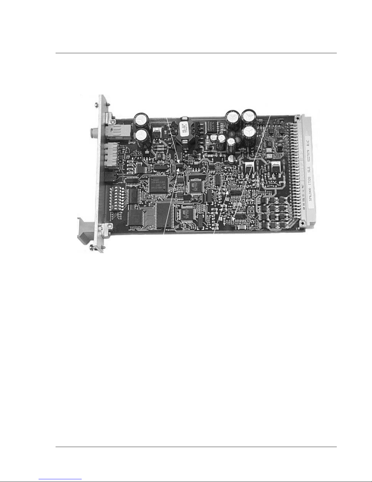
Jumpers Model 3
JP1 Must always be strapped in normal operation. The strap enables the
watchdog.
JP2 Never strapped during normal operation.
JP1 and JP2 are only strapped differently during production when the card is
programmed the first time.
JP3 Normally strapped.
JP4 Normally strapped.
JP3 and JP4 can be used to enhance reception of loop communication in case of
loops with communication problems.
JP1
JP3
JP4
JP2

Service manual CS3000 Chapter 3: Loop processor board SPK-2 3-8
The circuit boards of the central unit
Document no.: S-4-007.875/E
Prepared: 1995-03-17 Fia
Revision: R4 2004-03-15 BM
© 2002, Consilium Marine AB
Technical data Model 1 & 2
Board size: Single Europe board, 100 x 160 mm
Front panel: Anodised aluminium, width 6 TE(30.1 mm)
Ambient temperature: -10°C to +70°C
Ambient humidity: 96% Rh
Input power: U
in
: 24 VDC (-20% - + 25%)
Current consumption: I
in nom
: 90 mA
I
in max
: 160 mA
Output voltage: U
ut
: 30 VDC (+/- 5%)
Output current: I
ut nom
: 45 mA
I
ut max
: 125 mA
Model 3
Board size: Single Europe board, 100 x 160 mm
Front panel: Anodised aluminium, width 6 TE(30.1 mm)
Ambient temperature: -10°C to +70°C
Ambient humidity: 96% Rh
Input power: U
in
: 24 VDC (-20% - + 25%)
Current consumption: I
in nom
: 120 mA (no loop units connected)
I
in max
: 1300 mA
Output voltage: U
ut
: 32 - 34 VDC
Output current: I
ut max
: 300 mA/loop
Service manual CS3000 Chapter 3: Alarm processor board LPK-2 3-9
The circuit boards of the central unit
Document no.: S-4-007.875/E
Prepared: 1995-03-17 Fia
Revision: R4 2004-03-15 BM
© 2002, Consilium Marine AB
Alarm processor board LPK-2
General
The alarm processor board LPK-2 controls and supervises the external alarm
devices. The board also controls external functions such as fans, fire doors and
release of fire extinguishing agents through relay outputs. The LPK-2 also
monitors all communication within its own central with all loop processor
boards. The LPK-2 that is situated in the main central unit also monitors all
communication on the system loop with control units and with external
computers, printers, etc.
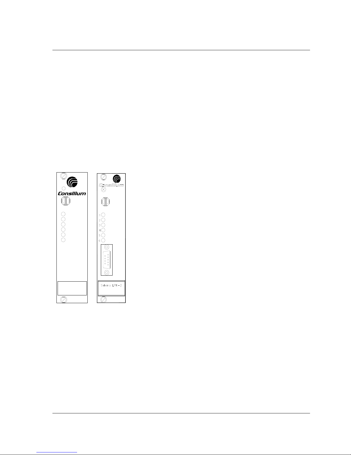
The alarm processor board exists in two different models, which differ only in
the exterior of the front panel. Model 2 has an additional connector for
downloading data from a computer.
Handling
1
2
3
4
5
6
Salwico LPK-2
Model 1 Model 2
Indications
There are six LEDs on the front panel of the board.
No 1 (green) when lit: proper voltage supply.
No 2 (red) when lit: fire alarm has been given on the fire
brigade relay output.
No 3 (yellow) when lit: fault has been detected.
No 4 (yellow) when lit: local system failure
No 5 (green) (in service mode) will flash synchronously with the
central unit’s communication with the
loop-PCB.
No 6 (green) (in service mode) will flash synchronously with the
communication on the system loop.
Fuse
The battery voltage is fused. If the fuse is blown a signal is activated in
the back plane. The fuse is accessible on the front panel of the board,
and can be used for disconnecting the power.
Fuse rating: 1 A 5x20 mm
Setting the address
The address of the board is set with a DIP-switch (SW1), with 8 switches.
• Sw 6 (when set) activates the service mode.
• Sw 7 (when set) allows communication only on loop 1 (the primary loop).
• Sw 8 (when set) allows communication only on loop 2 (the secondary loop).
• Sw 6, 7, 8 (when set together) forces downloading of definition data.
The address interval is 1 - 16. The LPK-2 board controlling and supervising the
main central unit is always set to one. The addresses of the other LPK-2, if
installed in the system, are set according to the definition in the Definition
program.
Service manual CS3000 Chapter 3: Alarm processor board LPK-2 3-10
The circuit boards of the central unit
Document no.: S-4-007.875/E
Prepared: 1995-03-17 Fia
Revision: R4 2004-03-15 BM
© 2002, Consilium Marine AB
Restarting the board
Remove the fuse from the board to disconnect the power. When the fuse is put
back on, the board is restarted.
Replacing the board
To replace the LPK-2 follow these steps:
1. Disconnect the power by removing the fuse.
2. To avoid activation of Bells, remove fuses F5-F10 on ARK-2.
WARNING!
The power must be disconnected before the board is removed.
3. Remove the board and replace it with the new board.
Service manual CS3000 Chapter 3: Alarm processor board LPK-2 3-11
The circuit boards of the central unit
Document no.: S-4-007.875/E
Prepared: 1995-03-17 Fia
Revision: R4 2004-03-15 BM
© 2002, Consilium Marine AB
Function
Block diagram
OUTPUTS
RELAY
SYSTEM
COM. LOOP
(CSM/LPK)
(CSM/LPK)
COM. LOOP
SYSTEM
SYSTEM
SYSTEM
BUFFERS
DATA/ADDRESS
COM. CONTR.
INT.COM.
BASIC
1
12
10
9
8
8
6
7
2
5
4
3
BLOCK
24 VDC
LOOP 2
LOOP 1
ADDRESS/DATA/CONTROL
TX/RX
TX/RX
TX/RX
RX
TX
RX
TX
TX/RX
DIR
TX/RX
FUSE
SWITCH
LOOP
CONVERTER
11
BACK PLANE
LOOP (SPK)
ALARM
SIGNALS
BACK PLANE
WATCH-DOG
MEMORY
CPU
INDICATIONS
LED-
DC/DC
SWITCH
ADDRESS
CLOCK
REAL TIME

Service manual CS3000 Chapter 3: Alarm processor board LPK-2 3-12
The circuit boards of the central unit
Document no.: S-4-007.875/E
Prepared: 1995-03-17 Fia
Revision: R4 2004-03-15 BM
© 2002, Consilium Marine AB
1. DC/DC converter
The DC/DC circuit converts the battery voltage of the back plane to 5 VDC,
which is supplied to all logical circuits on the board.
2. CPU/Memory/Watchdog
This is the main block of the LPK-board. The CPU uses the memory circuits for
executing the programme code. There is also a non-erasable memory containing
the system configuration and the external controls. The watchdog supervises the
processor and checks that there are no hang-ups in the programme execution.
3. LED indications
One green LED indicates that the board is power supplied. If the watchdog is
activated (possible fault in the board), a yellow LED is lit, indicating system
fault. Furthermore there are two LEDs (one yellow and one red) indicating fault
and alarm in the central unit. Finally there are two green LEDs that are used for
service purposes.
4. Address switch
With the DIP switch the 8-bit address of the LPK is set.
5. Real time clock
The real time clock is keeping track of the time in the system. The clock has
built-in registers for seconds, minutes, hours, days, week-day, month and year
(including leap-years). The real time clock is reset from the control panel.
6. Internal communication loop (RS485)
The internal communication loop is connected to all SPKs in the same rack
system. All SPKs are polled and supervised via this loop.
7. Loop switch
The loop switch changes the communication channel from one external loop to
the other.
8. System communication loop (RS422)
This block contains the communication with control units and other central
units.
9. Data/address buffers
All bus connections going from the back plane are buffered in special buffer
circuits.
10. Back plane signals
Certain hardware signals in the back plane are read by the LPK after a voltage
conversion.
11. Basic-alarm
The basic-alarm function is activated if a SPK or the LPK is faulty and therefore
incapable of transmitting an alarm. This board will block the basic-alarm
function if the processor is in proper working order.
12. Fire brigade output
Two relay outputs for connection to the fire brigade. The alarm relay is
programmable and the other relay is activated when there are not muted faults in
the system.

Service manual CS3000 Chapter 3: Alarm processor board LPK-2 3-13
The circuit boards of the central unit
Document no.: S-4-007.875/E
Prepared: 1995-03-17 Fia
Revision: R4 2004-03-15 BM
© 2002, Consilium Marine AB
Technical data
Board size: Single Europe board, 100 x 160 mm.
Front panel: Anodised aluminium, width 6 TE (30.1 mm).
Ambient temperature: -10°C to +70°C.
Ambient humidity: 96% Rh.
Input power: U
in
: 24 VDC (-20% - + 25%).
Current consumption: I
in nom
: 80 mA
I
in max
: 120 mA.
Outputs: 2 relays, 480 mA, 125 V
Service manual CS3000 Chapter 3: Relay board ARK-2 3-14
The circuit boards of the central unit
Document no.: S-4-007.875/E
Prepared: 1995-03-17 Fia
Revision: R4 2004-03-15 BM
© 2002, Consilium Marine AB
Relay board ARK-2
General
Orders to the alarm devices and controls issued by the LPK is executed by the
relay board. The alarm device outputs can also be activated by a basic-alarm
via the back plane. Furthermore the relay board may be used for monitoring
external signals and for supervision of power supply to external units.
Handling
Indications
The LED on the front panel of the board is lit every time the board is polled.
Fuses
There are 14 fuses on the front panel..
F1 Output 24 VDC 1+ F2 Output 24 VDC 1F3 Output 24 VDC 2+ F4 Output 24 VDC 2F5 Alarm bell output 1+ F6 Alarm bell output 1F7 Alarm bell output 2+ F8 Alarm bell output 2F9 Alarm bell output 3+ F10 Alarm bell output 3F11 Relay output RL1 F12 Relay output RL2
F13 Relay output RL3 F14 GA-output
Fuse rating: 2 AT 5x20 mm
Salwico ARK-2
F13
F11
F9
F7
F5
F3
F1 F2
F4
F6
F8
F10
F12
F14

Service manual CS3000 Chapter 3: Relay board ARK-2 3-15
The circuit boards of the central unit
Document no.: S-4-007.875/E
Prepared: 1995-03-17 Fia
Revision: R4 2004-03-15 BM
© 2002, Consilium Marine AB
Jumper "PLUS"
With this jumper the pulse type can be altered. In the left position the pulse is
internally generated, in the right position the pulse comes from an external
source.
Switch S9
This switch is found on the front panel and is used for resetting the basicalarm.
Switch SW1
SW1-1, SW1-2, SW1-3 (B1, B2, B3)
"ON" : Steady signal to corresponding alarm bell output.
"OFF": Pulsed signal to corresponding alarm bell output.
SW1-4, SW1-5, SW1-6 (R1, R2, R3)
"ON" : Steady signal to the outputs of relays RL1-RL3.
"OFF": Pulsed signal to the outputs of relays RL1-RL3.
SW1-7 (GA)
"ON" : Signal in step with the signal on the GA-input.
"OFF": Pulsing signal
Replacing the board
To replace the ARK-2 follow these steps:
1. Shut down the central by removing the fuses F3-F6 on the KE-2 rectifier.
WARNING!
The power must be disconnected before the board is removed.
2. Remove the board and replace it with the new board.
3. Start up the central by inserting F3+F4 and F5+F6 in that order.
Service manual CS3000 Chapter 3: Relay board ARK-2 3-16
The circuit boards of the central unit
Document no.: S-4-007.875/E
Prepared: 1995-03-17 Fia
Revision: R4 2004-03-15 BM
© 2002, Consilium Marine AB
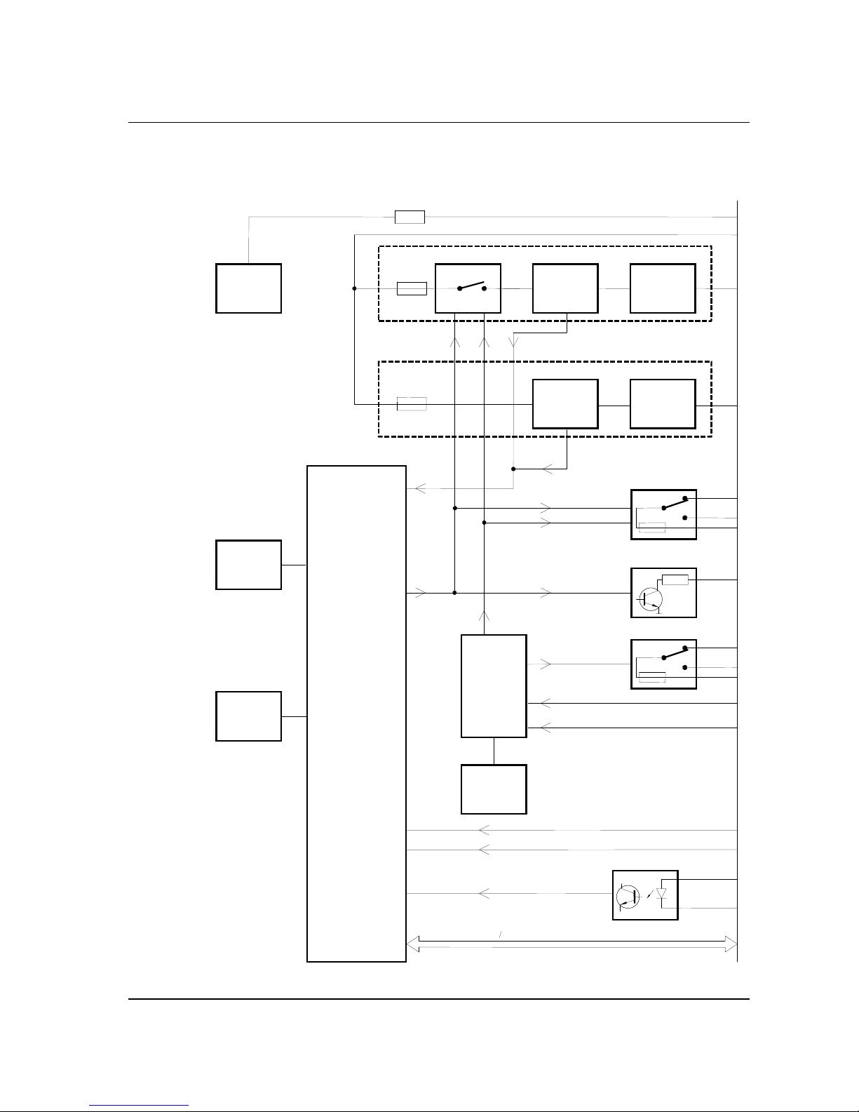
Function
Block diagram
IN PUT
SIG NALS
CONTROL
BASIC ALAR
M
LED
PA NEL
SW ITCH
DIP
PTC
BARRIERFA ULT
BACK PLANE
PTC
uP BUS
OP TO I S OL.
EXT. FUSE FAULT
SW ITCH
PA NEL
15
14
13
12
17
16
11
10
9
8
7
EPLD/ PI
1
4
3
6
5
2
LOG IC
GA
GA INTERM. INPU
T
GA INPUT
OUTPUT
GA - RELA
Y
OUTPUT
FIRE/ FAUL
T
RELAY OUTPU
T
POWER SUP PL Y
ALARM DEVI CE
DET.
FA ULT
BARRIERFA ULT
FUSE
FUSE
CONVERTE
R
DC/ DC
 Loading...