

Consew 357R-1 User Manual
-----------~5./nce
'B.9B
DNSE
CONSOLIDATED SEWING MACHINE CORP.
I INDUSTRIAL SEWING & CUTTING EQUIPMENT
PARTS
LIST
&
INSTRUCTION
MANUAL
357R-1
....____
INDUSTRIAL
400 VETERANS BLVD, CARLSTADT,
SEWING
&
CUTTING
EQUIPMENT
NJ
07072

CONTENT
Operation
I
...
Brief
II
...
Main specification·······························································.······················································································ 1
ITT'\
r nstall ing the
1.lnstalling
2.Installing
3.Installing
4.Connecting
5.
Installation
6.lnstalling
7.
Installing
IV
...
Preparation
1 .Clean the tnach ine ............................................................................................................
2.E-xan1ination
V
...
Operation
1.Choosing
2.lnstalling
3.Threading
4.
Winding the
Instruction
introduction··· ....................................................
Machine
the
Machine
the n1otor ......................................................................................................................................................... 1
the
bobbin
the clutch lever to pedal ..................................................................................................................... ··2
and
adjustment
the drip pan ..................................................................................................................................
the
thread
··············································································································~····················································
........
: ........................................................................................................................................... .-.................. 4
and Adjustn1ent ..................................................................................................................................... 4
the
thread
the
needle
the
needle
bobbin
··············································:···························································································
head ............................................ ; .......................................................................................... 1
winder
unwinder
......................................................................................................................................................... 4
....................................................................................................................................................... 4
thread ......................................................................................................................................... 4
thread .......................................................................................................................................... 5
.......................................................................................................................................
of
knee I ifter
.................................................................................................................................
device
,.
.............................................................................. ·
.............................................................................................
: ............................................... 3
................
::
................
1
..
1
2·
··
2
3
··
3
3
5.Installing
6.Adjusting
?.Adjusting
&.Adjusting the
9.Adjusting
1
O.The relation between the hook and hook
ll.Adjusting
Parts
l.Artn
2.Thread
3.
Post
4.Postbed
5.Upper
6.Presser
7.
Reverse
8.Lower
9.Accessory
the bobbin into the hook
stitch
length and reverse
the tension
height
the
position
the
position
ofbobbin
of
feed dog and the
of
hook and
of
feed
.................................................................................................................................
sewing
thread and
needle
dog
and
Manual
········································································································································································ 1
tension
bed ................................................................................................................................................................
shaft
foot lifter ..............................................................................................................................................
feed ........................................................................................................................ ~ ...................... :
shaft
....................................................................................................................................................
for twin needle ................................................. , ..............................................................................
and needle thread take-up ......................................................................................................
.........................................................................................................................................................
............................................................................................................................................................
............................................................................................................ 5
needle
pressure
thread
needle
thread .............................................................................. 6
of
presser
........................................................................................................ 7
separate
.................................................................................................. 9
bar ................................................................ 7
bracket
.............................................................. 8
.....
5
0~
11
12~
13
14~
15
16~17
18~19
20~21
22~23
24~25
26~27
Operation
The
using
directions
the
machine
should
and
taken
Instruction
be
read
carefully
adequate
before
maintenance
I ,
Brief
Introduction
II
,
Main
specification
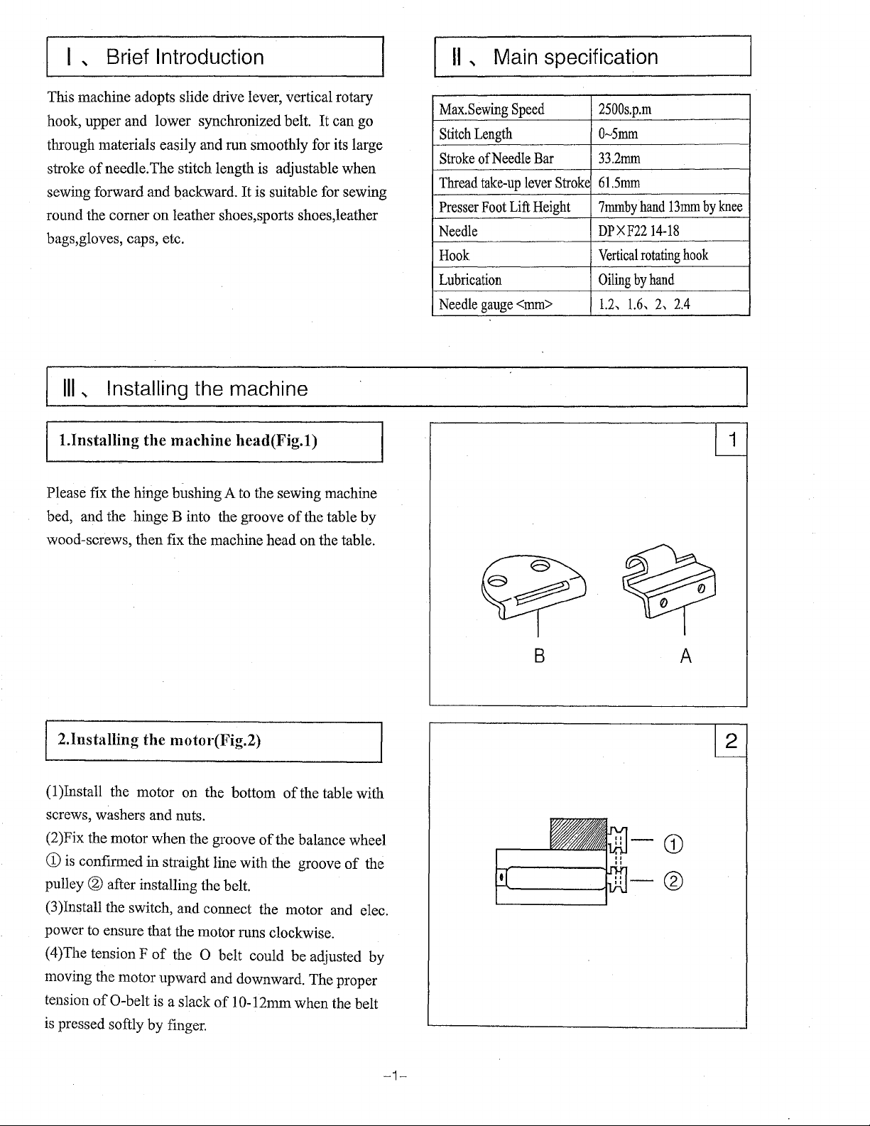
This machine adopts slide drive lever, vertical rotary
hook, upper and lower synchronized belt.
through materials easily and run smoothly for its large
stroke
of
needle. The stitch length is adjustable when
sewing forward and backward.
round the comer on leather shoes,sports shoes,leather
bags,gloves, caps, etc.
Ill
,
Installing
l.lnstalling the machine head(Fig.l)
Please fix the hinge bushing A to the sewing machine
bed, and the hinge
wood-screws, then fix the machine head on the table.
the
B into the groove
It
is suitable for sewing
machine
It
can go
of
the table by
Max.Sewing
Stitch
Length
Stroke
of
Needle
Thread
take-up
Presser
Foot
Needle
Hook
Lubrication
Needle
gauge
Speed
Bar
lever
Lift
Height
<mm>
Stroke
2500s.p.m
Q....,Smm
33.2mm
61.5mm
7mmbyhand
DPXF2214-18
Vertical
Oiling
1.2,
rotating
by
hand
1.6,
13mm
2,
2.4
by
hook
knee
I 2.lnstalling the motot·(Fig.2)
(1
)Install the motor on the bottom
screws, washers and nuts.
(2)Fix the motor when the groove
CD
is
confirmed in straight line with the groove
pulley
® after installing the belt.
(3
)Install the switch, and connect the motor and elec.
power to ensure that the motor nms clockwise.
( 4)The tension F
moving the motor upward and downward. The proper
tension
is
of
pressed softly by finger.
0-belt
of
the 0 belt could be adjusted by
is
a slack
of
1 0-12mm when the belt
of
the table with
of
the balance wheel
of
the
B
A
CD
®
-1-
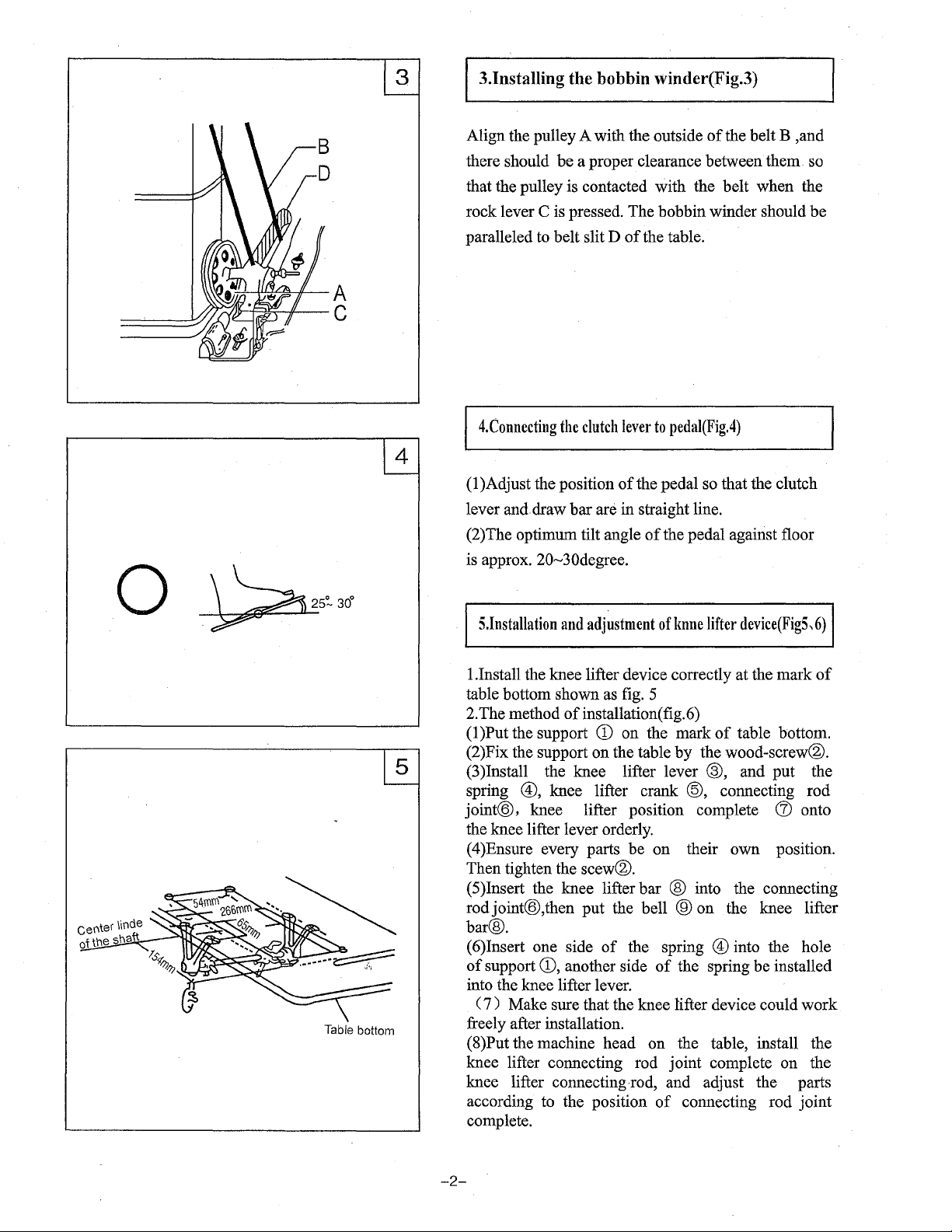
3.1nstalling the bobbin winder(Fig.3)
-~~-!:?l:-11--A
/Jrr--1~-11--
c
Align the pulley A with the outside
there should be a proper clearance between them. so
that the pulley is contacted with the belt when the
Cis
rock lever
paralleled to belt slit D
4.Connecting
(1
)Adjust the position
lever and draw bar
(2)The optimum tilt angle
is approx. 20--JOdegree.
pressed. The bobbin winder should be
of
the table.
the
clutch
lever
to
of
the pedal so that the clutch
are in straight line.
of
of
the belt B ,and
pedai(Fig.4)
the pedal against floor
Table bottom
S.lnstallation
1.Install the knee lifter device correctly at the mark
table bottom shown
2.
The method
(1
)Put the support
(2)Fix the support on the table by the wood-screw®.
(3)Install the knee lifter lever
spring
joint@, knee lifter position complete
the knee lifter lever orderly.
(4)Ensure every parts be on their own position.
Then tighten the
( 5)Insert the knee lifter bar @ into the connecting
rodjoint@,then put the bell
bar@.
( 6)Insert one side
of
support
into the knee lifter lever.
(
7)
Make sure that the knee lifter device could work
freely after installation.
(8)Put the machine head on the table, install the
knee lifter connecting rod joint complete on the
knee lifter connecting
according to the position
complete.
and
adjustment
as
of
installation(
CD
of
knne
fig.
5
fig.
6)
on the mark
lifter
device(FigS,
of
table bottom.
®, and put the
®,
knee lifter crank @, connecting rod
scew®.
CD,
another side
®on
of
the spring ® into the hole
of
the spring be installed
-rod,
and adjust the parts
of
the knee lifter
connecting rod joint
(J)
6)
of
onto
-2-
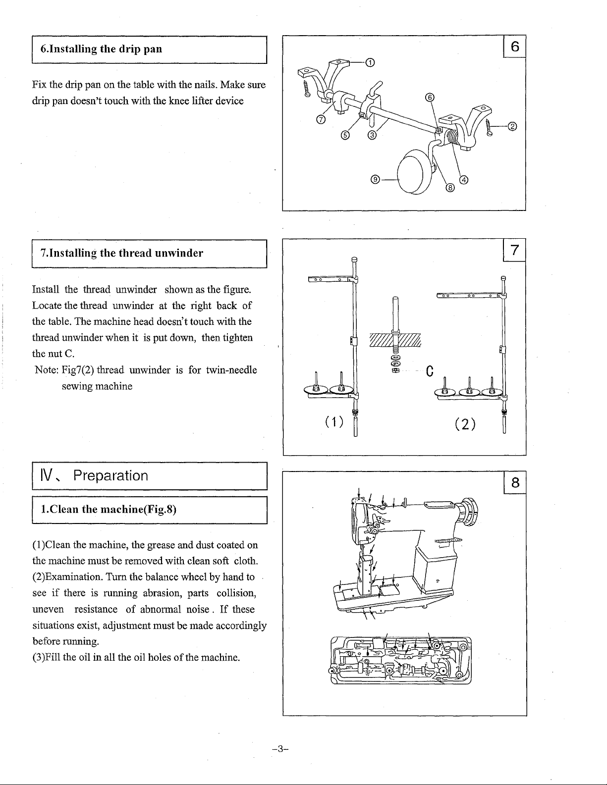
6.Installing the drip pan
Fix the drip pan on the table with the nails. Make sure
drip pan doesn't touch with the knee lifter device
~7_.I_n_s_t_a_n_in_g_·
Install the thread unwinder shown as the figure.
Locate the thread unwinder at the right back
the table. The machine head doesn't touch with the
thread unwinder when it is put down, then tighten
the nut
Note: Fig7(2) thread unwinder is for twin-needle
C.
sewing machine
IV,
_tl_te
__
th_r_e_a_d_u_n_w
Preparation
__
in_d_e_r
________
of
~l
( 1 )
~
(2)
l.Clean the machine(Fig.8)
( 1 )Clean the machine, the grease and dust coated on
the machine must be removed with clean soft cloth.
(2)Examination. Tum the balance wheel
see
if
there is running abrasion, parts collision,
of
uneven resistance
situations exist, adjustment must be made accordingly
before running.
(3)Fill the oil in all the oil holes
abnormal noise .
of
by
hand to
If
these
the machine.
-3-
2.Examination
When the machine is put into use or use again after
operation for a ling time, please lift the roller presser
of
foot and run the machine at lower speed
p.m, After running
speed gradually.
JO
min, then increase up sewing
1200-1500s.
II
I
-~
~
I
z
CD
CD
0..
ro
<0
a
~
f
a.
Two
grooves
opposite
V...
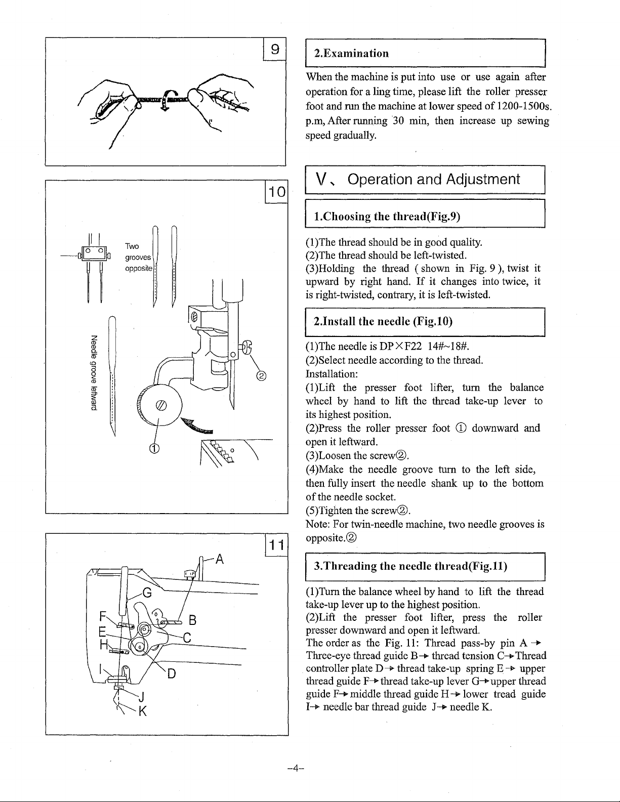
l.Choosing the thread(Fig.9)
(1)The thread should be in good quality.
(2)The thread should be left-twisted.
(3)Holding the thread ( shown in Fig. 9 ), twist it
upward by right hand.
is
right-twisted, contrary, it is left-twisted.
12.1nstall the needle (Fig.lO)
(1)The needle is
(2)Select needle according to the thread.
Installation:
(1)Lift the presser foot lifter, tum the balance
wheel by hand to lift the thread take-up lever to
its highest position.
(2)Press the roller presser foot
open it leftward.
(3
)Loosen the screw®.
Operation and Adjustment
If
it changes into twice, it
DPXF22
14#~18#.
CD
downward and
( 4 )Make the needle groove tum to the left side,
then fully insert the needle shank up to the bottom
of
the needle socket.
(5)Tighten the
Note: For twin-needle machine, two needle grooves is
opposite.®
screw®.
A
3.Threading
( 1 )Tum the balance wheel by hand to lift the thread
take-up lever up to the highest position.
(2)Lift the presser foot lifter, press the roller
presser downward and open it leftward.
The order as the Fig.
Three-eye thread guide
controller plate
thread guide
guide
I__...
-4-
needle bar thread guide J-+ needle
F-+-thread take-up lever
F~
middle thread guide
the
needle
D--. thread take-up spring
thread(Fig.ll)
11:
Thread pass-by pin A -+
B-+
thread tension
Q-.upper
H-+
lower tread guide
K.
c~
E-+
Thread
upper
thread
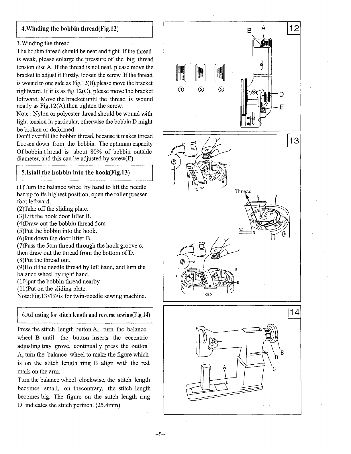
4.\Vinding the bobbin thread(Fig.12)
1.
Winding the thread
If
The bobbin thread should be neat and tight.
is weak, please enlarge the pressure
tension disc A.
bracket to adjust it.Firstly, loosen the screw.
is
wound
rightward.
leftward. Move the bracket until the thread is wound
neatly as Fig.12(A).then tighten the screw.
Note:
Nylon
light tension in
be
broken or deformed.
Don't overfill the bobbin thread, because it makes thread
Loosen down from. the bobbin. The optimum capacity
Of
bobbin t bread is about 80%
diameter, and this can
If
the thread is not neat, please move the
to
one side
If
as
Fig.12(B),please move the bracket
it is as fig.12(C), please move the bracket
or
polyester thread should be wound with
particular, otherwise the bobbin D might
be
adjusted
of
of
by
the thread
the
big thread ,
If
the thread
bobbin outside
screw(E).
® ®
B
A
S.Istall
( 1 )Turn the balance wheel
bar
foot leftward.
(2)Take
(3)Lift the hook door lifter B.
(4)Draw out the bobbin thread Scm
(S)Put the bobbin into the hook.
(6)Put down the door lifter B.
(7)Pass the Scm thread through the hook groove c,
then draw out the thread from the bottom
(8)Put the thread out.
(9)Hold the needle thread
balance wheel
(1
O)put
11
(
Note:Fig.13<B>is for twin-needle sewing machine.
6.Adjusting
Press the stitch length button A, turn the balance
wheel B until the button inserts the eccentric
adjusting tray grove, continually press the button
A, turn the balance wheel to make the figure which
is on the stitch length ring B align with the red
mark on the arm.
Turn the balance wheel clockwise, the stitch length
becomes small,
becomes big. The figure
D indicates the stitch perinch. (2S.4mm)
the
bobbin into the hook(Fig.l3)
by
hand to lift the needle
up to its highest position, open the roller presser
off
the sliding plate.
of
D.
by
left hand, and turn the
by
right hand.
the bobbin thread nearby.
)Put on the sliding plate.
for
stitch
length
and
reverse
on
thecontrary, the stitch length
on
the stitch length ring
sewing(Fig.14)
Thread
-5-
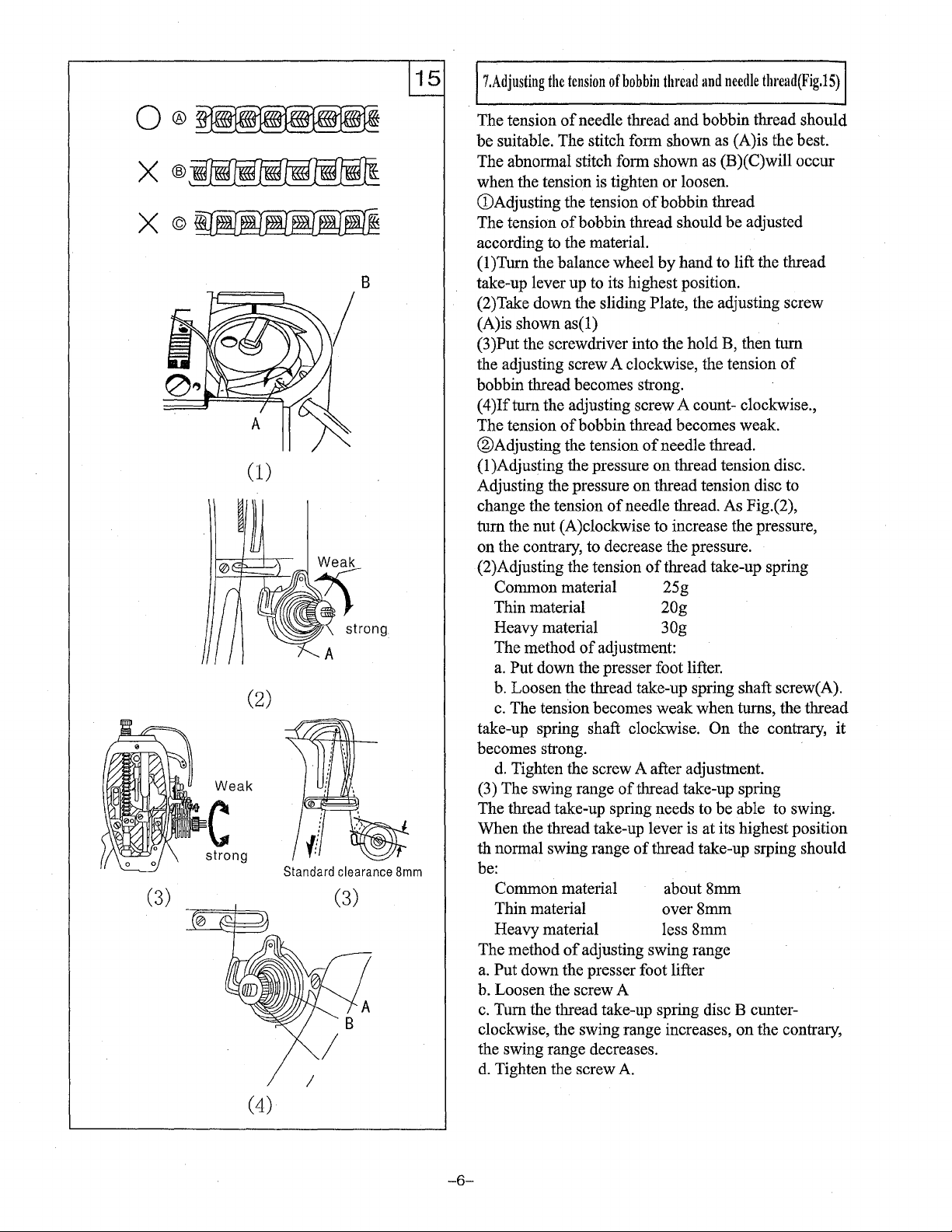
7.Adjusting
the
tension
of
bobbin
thread
and
needle
thread(Fig.lS)
Q®
X®
X©
(3)
(1)
(2)
Weak
c
(4)
Standard
I
strong:
clearance
8mm
The tension
be suitable. The stitch form shown as (A)is the best.
The abnormal stitch form shown as (B)(C)will occur
when the tension is tighten or loosen.
(!)Adjusting the tension
The tension
according to the material.
(l)Turn the balance wheel
take-up lever up to its highest position.
(2)Take down the sliding Plate, the adjusting screw
(A)is shown
(3)Put the screwdriver into the hold B, then turn
the adjusting screw A clockwise, the tension
bobbin thread becomes strong.
(4)Ifturn the adjusting screw A count- clockwise.,
The tension
®Adjusting the tension
(1
)Adjusting the pressure on thread tension disc.
Adjusting the pressure on thread tension disc to
change the tension
turn the nut (A)clockwise to increase the pressure,
on the contrary, to decrease the pressure.
(2)Adjusting the tension
Common material 25 g
Thin material
Heavy material 30g
The method
a.
Put down the presser foot lifter.
b. Loosen the thread take-up spring shaft screw( A).
c.
The tension becomes weak when turns, the thread
take-up spring shaft clockwise.
becomes strong.
d.
Tighten the screw A after adjustment.
(3) The swing range
The thread take-up spring needs to be able to swing.
When the thread take-up lever is at its highest position
th normal swing range
be:
Common material about 8mm
Thin material over 8mm
Heavy material less 8mm
The method
a.
Put down the presser foot lifter
b. Loosen the screw A
c.
Turn the thread take-up spring disc B cunter-
clockwise, the swing range increases, on the contrary,
the swing range decreases.
d.
Tighten the screw
of
needle thread and bobbin thread should
of
bobbin thread
of
bobbin thread should be adjusted
by
hand to lift the thread
as(l)
of
ofbobbin
of
of
adjusting swing range
thread becomes weak.
of
needle thread.
of
needle thread. As Fig.(2),
of
thread take-up spring
20g
adjustment:
On
of
thread take-up spring
of
thread take-up srping should
A.
the contrary, it
-6-
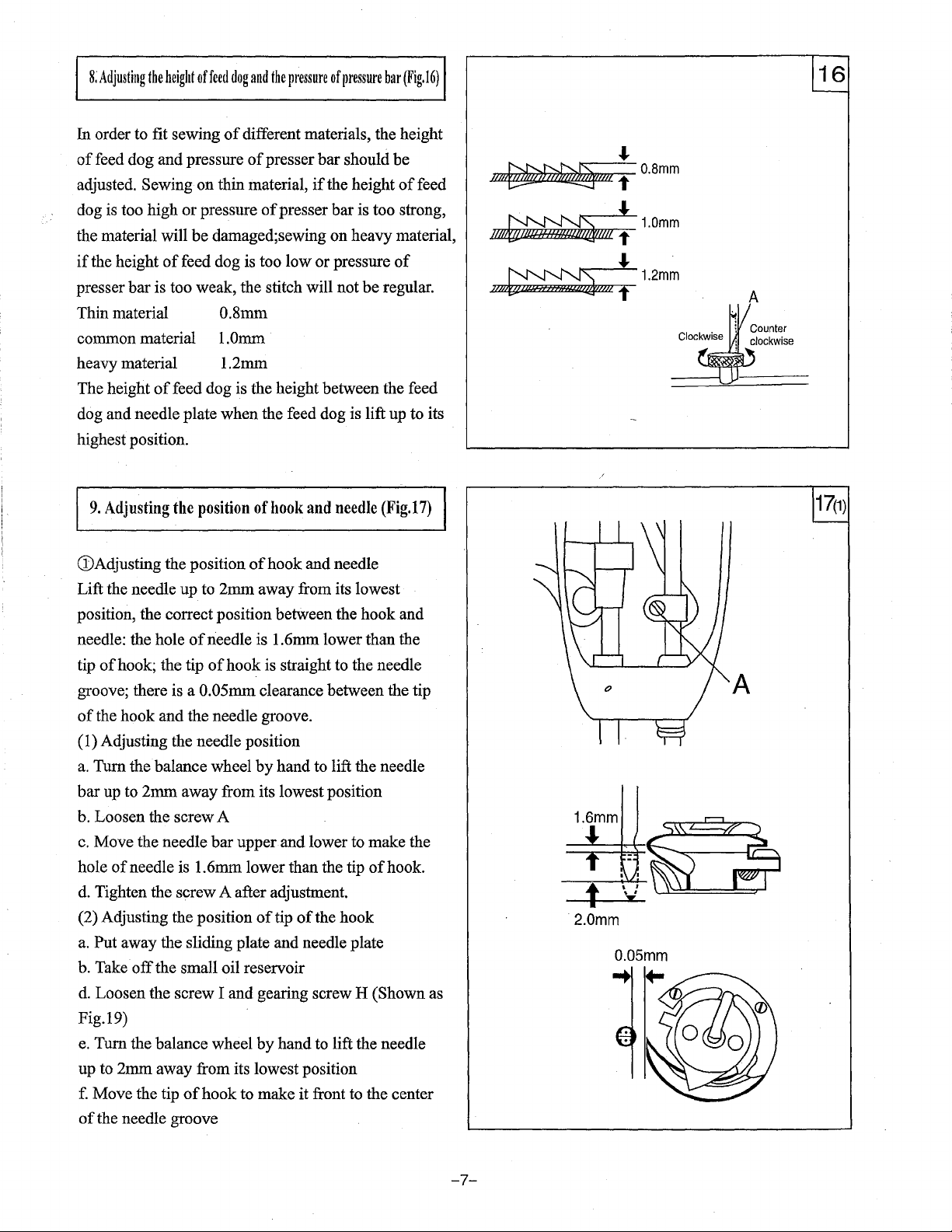
8;
Adjusting
the
height
of
feed
dog
and
the
pressure
of
pressure
bar
(Fig.16)
In order to fit sewing
of
feed dog and pressure
adjusted. Sewing on thin material,
dog is too high
the material will
if
the height
presser
Thin material 0.8mm
common material
heavy material 1.2mm
The height
dog and needle plate when the feed dog is lift up to its
highest position.
9.
Adjusting
CD
Adjusting the position
Lift the needle up to
position, the correct position between the hook and
needle: the hole
tip
of
groove; there is a 0.05mm clearance between the tip
of
the hook and the needle groove.
(1) Adjusting the needle position
a.
Turn the balance wheel
bar
up to
b. Loosen the screw A
c.
Move the needle
hole
of
d.
Tighten the screw A after adjustment.
(2) Adjusting the position
a.
Put away the sliding plate and needle plate
b. Take
d.
Loosen the screw I and gearing screw H (Shown as
Fig.19)
e.
Turn the balance wheel
up to
f.
Move the tip
of
the needle groove
of
bar
is too weak, the stitch will not
of
feed dog is the height between the feed
the
hook; the tip
2mm
needle is 1.6mm lower than the tip
off
the small oil reservoir
2mm
away from its lowest position
of
different materials, the height
of
presser
or
pressure
be
damaged;sewing on heavy material,
feed dog is too low
position
of
needle is 1.6mm lower than the
of
away from its lowest position
bar
of
hook to make it front to the center
of
l.Omm
of
hook
of
hook and needle
2mm
away from its lowest
hook is straight to the needle
by
upper and lower to make the
of
by
bar
should
if
the height
presser
hand to lift the needle
tip
hand to lift the needle
or
and
of
the hook
bar
is too strong,
pressure
be
regular.
needle
(Fig.17)
of
be
of
of
hook.
feed
~Mt
!~tilt
~//W
174
·2.0mm
j..
j..
t
0.8mm
1.0mm
1.2mm
A
-7-
 Loading...