

Page 1

OPERATING
INSTRUCTIONS
3421UX5-1
400 VETERANS BLVD, CARLSTADT, NJ 07072
Page 2

CONTENTS
DESCRIPTION ........................... 3 OPERATOR INFORMATION ......... 5-8
LUBRICATION ........................... 5
INSTALLATION……..... .......... 4 ADJUSTMENT ....................................... 8-17
INDEX
Description of Machine ............ ..3
General Characteristics………..3
Special Features……………….3
Feed Bar, Height........................12
Feed Dog, Centralizing…….... 12
Height………………………. 12
Lengthwise Setting………….. 12
Sidewise Setting……………...12
Timing……………………….13
Feed Roll, Pressure………….. ..9
Installation……………………4
Loop Deflector………………..13
Looper, Positioning………..... 14
Lengthwise Setting…………..14
Sidewise Setting…………….. 14
Timing………………………. 15
Lubrication…………………....5
Needles……………………………….6
Setting………………………………. ..6
Needle Bar, Height……………….….14
Needle Bar, Position………………....13
Needle Guard………………………..15
Presser Bar, Height…………………..11
Presser Foot, Pressure ......................... 8, 9
Speed ......................................................... .5
Stitch Length…………………………… 10
Spreader, Positioning…………………....16
Lengthwise Setting……………….......16
Sidewise and Height Setting…………......16
Take-up, Adjustment………………...17
Looper Thread……………………….17
Needle Thread……………………….17
Tension……………………………….8
Releaser……………………………..17
Arm Shaft……………………..5
Bed Shaft……………………...5
Other Points…………………..5
Threading…………………………….7
Upper………………………………...7
Lower………………………………...7
Page 3

DESCRIPTION
Consew model 3421UX5-1 is a high speed, compound
feed, two thread chainstitch machines designed for general
stitching operations on materials of medium and heavy
weight.
These machines are available for single and multiple
stitching operations such as seaming, binding, welting, lap seam
felling, etc. They perform outstanding work on trousers, work
clothing, automotive upholstery, tents, tarpaulins, seat covers
and a variety of other products.
General Characteristics
-Belt driven arm shaft mounted in front and rear ball bearings.
-Belt driven bed shaft.
-Semi-automatic lubricating system with large capacity oil
reservoir in upper and lower shafts lubricates all principal
bearings.
-Presser foot is raised by a treadle operated foot lifter which
also releases the needle thread tension.
-Space at right of needle, 10 inches.
Page 4
INSTALLATION
.?
OIL P A N
Fig. 2
r
Fig. 3
Fig. 4
OIL DRAIN JAR
FOOT LIFTER
LEVER
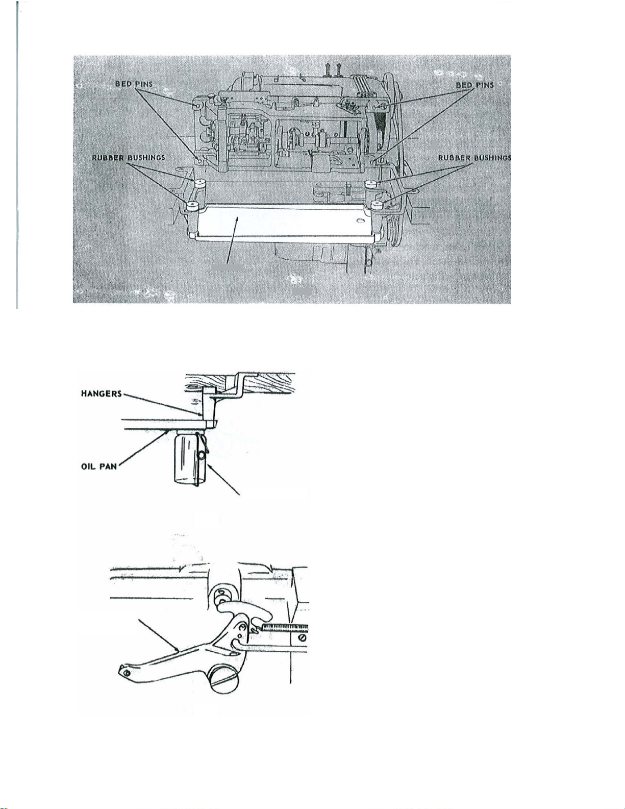
Assemble oil pan to hangers. Insert assembled oil pan into machine cut-out of table
placing four rubber bushings in hanger holes
as shown in Fig. 2. Attach oil drain jar to oil
pan as shown in Fig. 3.
Place machine on oil pan assembly with the
four bed pins passing through the four rubber
bushings shown in Fig. 2.
Connect foot lifter treadle to foot lifter
lever, Fig. 4, at back of machine by chain furnished for this purpose.
Page 5
LUBRICATION
Consew model 3421UX5-1 has a semi-automatic
lubricating system comprising a hollow arm shaft
and a hollow bed shaft which act as oil reservoirs.
The oil is distributed to all of the principal bearings
by centrifugal force through small jets in the shafts
when the machine is in operation. Provision is also
made for hand lubricating other movable parts
which are not lubricated from the reservoirs.
BEFORE STARTING machine, the machine
must be oiled as instructed. Failure to do this will
result in damage to the machine.
Pressure Oil Can, furnished with the machine, is to be used to oil all points requiring
lubrication.
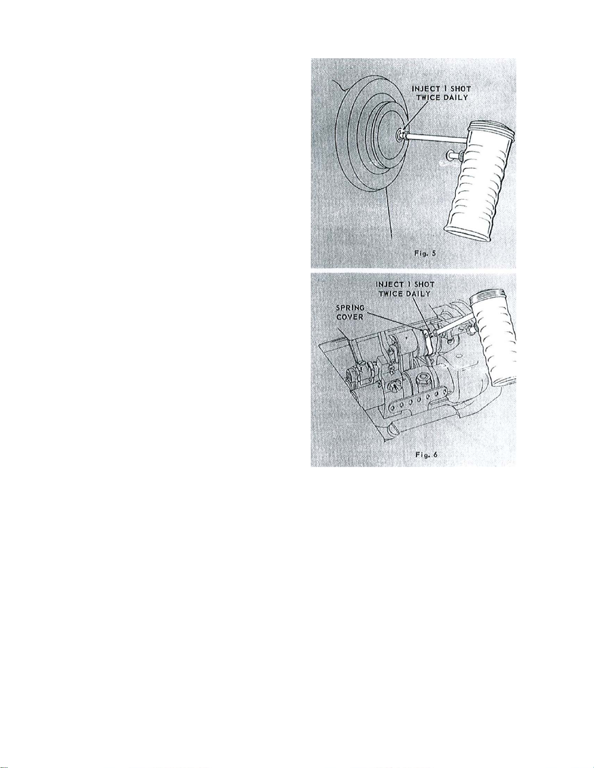
TO OIL ARM SHAFT
To fill arm shaft reservoir, insert spout of
pressure oil can excluded in hole, Fig.5, and
inject 1 shot of oil into shaft twice daily.
TO OIL BED SHAFT
To fill bed shaft reservoir, push spring cover, Fig.
6, to the left, insert spout of pressure oil can into
hole and inject 1 shot of oil into shaft twice daily.
Close oil hole spring cover.
NOTE: Bed shaft may also be oiled from
right hand end of machine.
OTHER OILING POINTS
Apply oil to all work plate and arm oil holes,
needle bar bearings and connections, needle bar
rock frame bearings, looper rocker sleeve and
presser lifting mechanism.
SPEED
Maximum speed for 32421UX5-1 is 4000 stitches
per minute.
It is advisable to operate new machines at a speed
of 500 stitches less than maximum for the first
100 hours of operation.
Maximum efficient speed is determined
upon the nature of the operation, the ability of
the operator and the type of material being sewn.
CAUTION: For machines in continuous
use, all oiling points must be oiled daily. Occasionally
oil tension release mechanism and looper pull-out
rack.
Page 6
NEEDLES
MOVE TO
SCARF OF
SCARF OF
Fig. 7
HIGHEST
POINT
LOOSEN
SCREW
For heavier weight material, needle 62 x59
may also be used. In this case, the needle bar
must be adjusted as instructed on page 13.
Use 62 x 59 for medium heavy work or 62 x 57 for
medium light work
The size of the needle to be used is determined
by the size of the thread which must pass freely
through the eye of the needle.
Orders for needles should specify quantity
required, size number and catalog number.
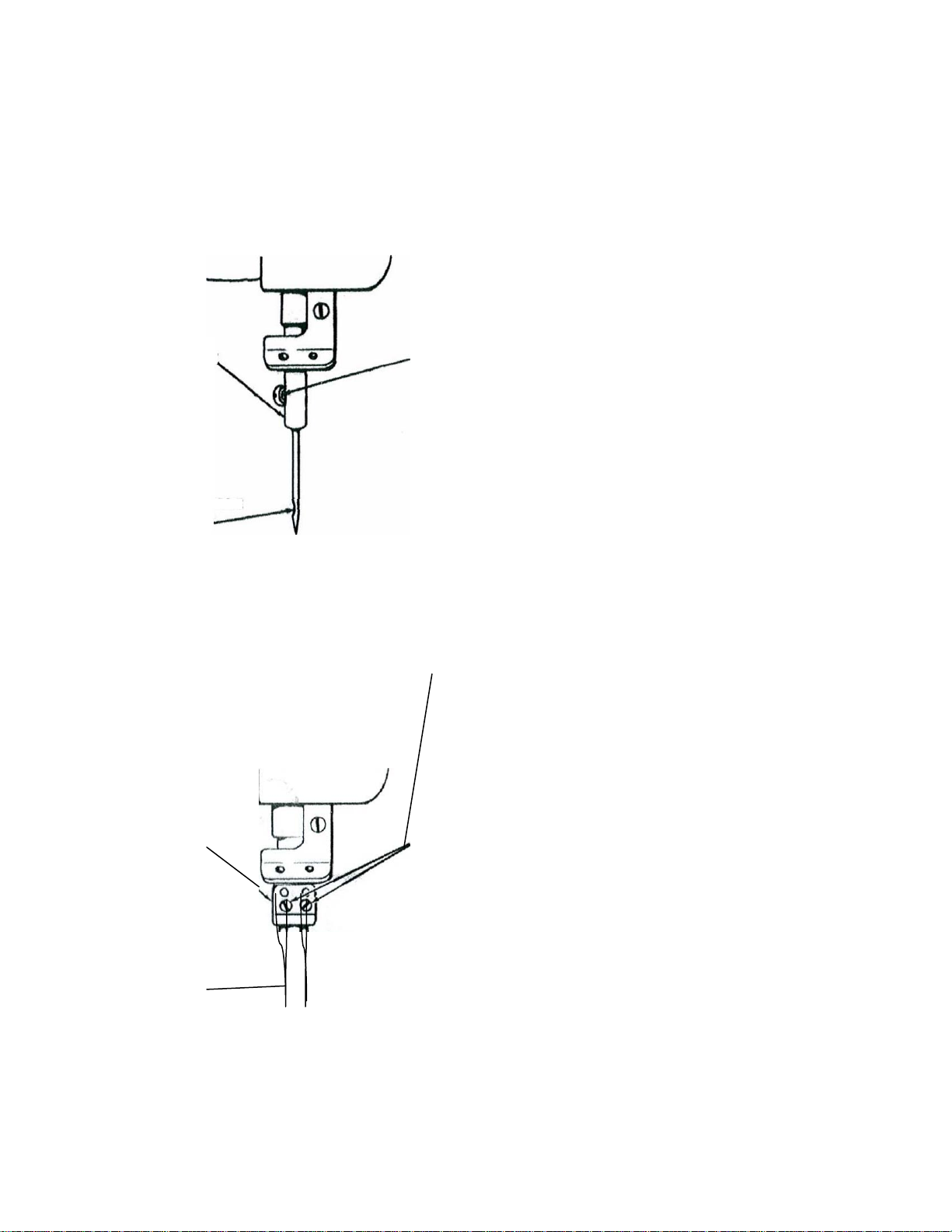
To Set the Needle
NEEDLE
TOWARD LEFT
MOVE TO
HIGHEST
POINT
LOOSEN
SCREWS
Turn machine pulley over toward the opera-
tor until the needle bar is at its highest point, as
shown in Fig. 7.
Loosen needle set screw on single needle
machines or needle clamping screws on multiple needle machines, as shown in Fig. 7.
Insert needle into needle bar or clamp as far
as it will go making certain that the scarf of
each needle faces toward the left, as shown in
Fig. 7.
THREAD
Either left twist or right twist thread may be
used in the needles and loopers.
Rough or uneven thread, or thread which
passes through the needle eye with difficulty
will interfere with successful operation of the
machine.
TOWARD
LEFT
Page 7

NEEDLE THREADS
Fig. 9
MORE
TENSION
TENSION
Tension on thread should be light as possible
while still sufficient to set the stitch correctly in
material.
LESS
TENSION
LOOPER THREADS
MORE
TENSION
LESS
TENSION
Fig. 10
PRESSURE
Pressure on material should be as light as
possible while still sufficient to insure correct
feeding.
Presser Foot Pressure
To regulate presser foot pressure, loosen
lock screw, Fig. 11, at rear of machine. Tighten
thumb screw to increase pressure; loosen to
decrease pressure. When correct feeding
pressure is attained, tighten lock screw.
Needle Thread Tension
To regulate needle thread tension, turn
thumb screw, indicated in Fig. 9, as may be required.
IMPORTANT: Regulate needle thread tension only when presser foot is down.
Looper Thread Tension
To regulate looper thread tension, turn
thumb screws, as indicated in Fig. 10, as may
be required.
Alternating Pressers:
To increase pressure, loosen lower lock nut
and loosen lock screw, then tighten upper lock
nut, see Fig. 12. When correct pressure is attained, tighten lock screw. Then tighten the
lower lock nut. To decrease pressure, loosen
upper lock nut and loosen lock screw, then
tighten lower lock nut. When correct pressure is
attained, tighten lock screw. Then tighten the
upper lock nut.
Page 8

Alternating Presser with Pneumatic
Pressure Control
Adjust height of Pressure Cylinder with
pulley. To regulate air pressure, loosen lock nut
pressure. The correct air pressure is set for
Fork rises to approximately 1/16 inch from the
must not be raised higher than 1/2 inch above
Upper Feed Roll Pressure
•
z
presser feet resting on throat plate. There
should be a clearance of 1/4 inch between the
Presser Bar Spring Fork and the bottom of
the cylinder. To raise cylinder, loosen lower
lock nut and tighten upper lock nut, see Fig.13
.To lower cylinder, loosen upper lock nut and
tighten lower lock nut. When correct adjustment is attained, tighten both lock nuts.
and turn adjusting thumb screw. Tighten thumb
screw to increase pressure; loosen to decrease
average feeding when the Presser Bar Spring
from the bottom of the cylinder. Tighten lock
nut and replace belt.
Pressure may be increased for very slow
speeds and short runs by raising the Presser
Bar Pressure Cylinder, see Fig. 13. Cylinder
Regulate Cylinder Air Pressure Control
Valve, Fig.14, with motor running at high
speed after removing belt from the machine
To regulate pressure of the upper feed roll,
turn thumb screw as shown in Fig.15.
Presser Bar Spring Fork when presser feet are
resting on the throat plate.
Page 9

STITCH LENGTH
CROSS
SHAFT
SET
SCREWS
WORM
SET SCREWS
Fig. 17
To adjust the stitch length, depress plunger,
Fig.16, located on top of arm. Continue to hold
plunger down and turn machine pulley toward
operator until plunger enters notch in arm shaft
eccentric. Then turn plunger to lock in
position. Depress button, Fig.16, located on
machine bed. Hold down, and turn machine
pulley toward operator to increase length of
stitch, or away from operator to decrease
length of stitch. Letter "A" on machine
pulley indicates the longest stitch. When
desired length, indicated by letter, is
opposite arrow on front of machine, release
button and turn plunger to right or left until it
springs outward.
CAUTION: Never turn machine pulley
with plunger in locked position until button
on machine bed is depressed.
COVER
WORM PLATE
GEAR COLLARS
Machine with Puller Feed
The length of the stitch is determined by
the stitch gears in the puller feed mechanism.
The compound feed stitch length should be
set slightly shorter than the stitch of the puller
feed.
To change Puller Feed gears for adjusting stitch length, remove the two cover plate
screws and remove cover plate, Fig. 17.
Loosen set screws. Slide puller feed shaft to
the right far enough to allow removal of worm
and worm gear. Place the new worm on cross
shaft. Turn worm in the operating direction and
tighten the first set screw into the flat of the
shaft. Then securely tighten both set screws,
checking for excessive end play. Engage the
new worm gear with the worm and slide puller
feed shaft through the worm gear until the end
of the shaft is flush with the needle bearing.
Remove end play in the shaft by setting the
two collars against the bracket and tightening
the four set screws. Align the lower feed roll
with the upper feed roll and tighten the two set
screws. Center the worm gear on the center of
the worm. Tighten the two set screws with the
first screw in the spline of the shaft. Replace
cover plate and adjust the compound feed.
Page 10

PRESSER BAR LIFT
i g .
When the presser foot is raised by the
presser bar lifter and the needle is at its highest position, the point of the needle should not
protrude below the presser foot.
To adjust, turn machine pulley over toward
operator until needle is at its highest position.
Loosen set screw, Fig. 18. Raise presser foot to
the correct height, place stop collar against upper bracket, and tighten the set screw.
Machines with Alternating Pressers
SET
SCREW
COLLAR
The lift the vibrating and lifting pressers
is controlled by an adjustable eccentric. To
adjust, remove arm cover at rear of machine.
Turn machine pulley over toward operator until
feeding presser is down. Loosen the two lock
screws, Fig. 19, and the two clamp screws.
Insert screw driver into notch of adjusting disc,
and turn machine pulley as indicated in Fig.
19. Then tighten the two clamp screws and the
two lock screws.
When it is desirable to have either one of the
pressers lift higher than the other, turn machine
pulley over toward operator until the lifting
presser is at its highest position. Loosen the
two clamp screws, Fig 20, and turn lifting rock
shaft crank up or down until desired lift of
each presser is attained. Then tighten the two
clamp screws.
CAUTION: Limit lift of pressers to
minimum required for the work, as this
permits higher speeds.
Fig. 18
The vibrating presser should be timed so that
under normal sewing conditions, the presser
foot will seat on the material at approximately
the same time the needle enters material. This
timing can be advanced or retarded slightly
depending on the type of operation being
performed, such as sewing over seams. To
adjust, loosen two holding screws, Fig. 20,
not more than one half turn. Then turn the
adjustable eccentric, Fig. 19, until the
vibrating presser seats at the correct time.
Securely tighten the two holding screws after
adjustment is made.
Page 11

TO SET FEED BAR AT CORRECT
1
HEIGHT
When the feed bar is set at the correct
height, the feed lift link clamp will be aligned
with the rock shaft timing fiat. To adjust, make
certain that the feed lifting crank timing screw,
Fig. 21,engages shaft spot correctly. Loosen
clamp screw and move the feed lift clam link to
correct position. Then tighten clamp screw.
CENTRALIZING FEED DOG
Sidewise Setting
Needle should enter needle hole of feed dog
with the same clearance between the needle
and left or right side of hole. To adjust, loosen
feed dog screws, Fig. 22. Move feed dog until
correct clearance is attained. Hold on position,
and tighten feed dog screws.
Additional adjustment, if necessary, may be
attained by loosening the four rock shaft collar
set screws, the two rock shaft crank clamp
screws, Fig.22, and feed lifting clamp screw,
Fig.21. Move complete assembly to required
position and tighten screws.
Lengthwise Setting
The feed dog should clear the ends of the
feed slots in the throat plate equally at both
ends of feed travel. To adjust, set feed for desired stitch length. Loosen the two rock shaft
crank clamp screws, Fig.22. Move feed rocker
forward or backward until correct positioning is
attained. Then tighten the two clamp screws.
SETTING FEED DOG AT CORRECT
HEIGHT
When the feed dog height is set correctly,
approximately the full depth of the teeth will
show above the throat plate. To adjust, loosen
lock nuts, Fig.23, and slightly loosen feed dog
clamping screw. To raise feed dog turn jack
screw clockwise; to lower turn jack screw
counter-clockwise and tap feed deg down.
When correct setting is attained, tighten the
clamping screws and lock nuts.
Page 12

TIMING FEED LIFT ECCENTRIC
NEEDLE
ROCK FRAME
Fig. 24
When the feed dog is at its highest position,
the top of the teeth should be parallel with, and
project full depth of teeth above upper surface
of throat plate. To adjust, insert screwdriver in
hole in feed strap and loosen the two set
screws, Fig 24. Move feed lift eccentric forward for earlier rise of feed dog, or backwards
for later rise. Then tighten the two set screws.
NEEDLE BAR POSITIONING
Needles should enter needle holes of feed
PRESS
BAR
CLAMP SCREWS
dog toward the front with approximately
the same clearance between the front of the
needles and the needle holes as at the side. To
PRESS
adjust, press needle bar rock frame, Fig. 25,
against drive arm, and at the same time loosen
the two driving arm clamp screws. Continue
holding the rock frame against the drive arm,
move needle bar to correct position and tighten
the two clamp screws.
Fig. 25
POSITIONING LOOP DEFLECTORS
When loop deflector, located on underside
feed dog, is positioned correctly, there should
be a clearance of approximately 1/32 inch between the right side of the needle and the loop
deflector. To adjust, move looper out of sewing
position and tilt machine back on its hinges.
Loosen loop deflector screws, Fig 26. Move
deflectors toward rear of feed dog as far as the
screw slots allow. Tighten slightly to allow for
further adjustment. Return looper to sewing
position and turn machine pulley until needle
bar has descended to bottom of the needle bar
stroke. Tap deflector to left or right until correct clearance is attained. Move looper out
of sewing position and tighten loop deflector
screws.
Page 13

SETTING THE LOOPER AT CORRECT DISTANCE FROM NEEDLE
•
Fig, 29
NEEDLE BAR
Fig. 30
Sidewise Setting
Move looper to extreme forward position.
Check clearance between heel of looper and
When the looper is correctly positioned, the
point of the looper just clears the scarf of the
needle on the forward stroke of the looper. To
adjust, turn machine pulley until the looper
point is directly opposide the center of the
loop deflector, Fig. 28, which should be approximately 1/16 inch. To adjust, loosen the
two looper set screws. Turn looper to left or
right until correct clearance is attained. Hold
in position and securely tighten the two set
screws.
needle. Loosen looper holder screw, Fig. 27,
and tap holder to left or right until correct
clearance is attained. Then securely tighten the
looper holder screw.
CAUTION: On single and multiple needle
machines, make certain that the point of each
looper just clears the scarf of its respective
needle. To adjust, with looper point directly
opposite center of needle, loosen the two set
screws, Fig 28, and turn looper slightly to left
or right. Then tighten the set screws.
LOOPER CARRIER
CLAMP NUT
Lengthwise Setting and Setting Height of
Needle Bar
When correctly set, the point of the looper
should be directly opposite the center of the
needle, and at the center of the clearance above
the eye of the needle when the looper timing
mark LT on machine pulley is opposite the
timing arrow on the arm.
CLAMP SCREWS
To adjust the looper, loosen looper carrier
clamping nut, Fig. 29. Move carrier forward or
backward until looper point is directly opposite
center of needle. Then tighten clamping nut.
To adjust needle bar, first make certain
that needle is inserted up into the needle bar
or clamp as far as possible. Loosen the two
needle bar clamping screws, Fig.30, and raise
or lower needle bar to correct position. Then
securely tighten the two clamping screws.
Page 14

TIMING LOOPER DRIVING CRANK
TIMING
TIMING
a",,,ro url
4
Fig. 31
1:e6C,7`•
et
When the looper driving crank is properly
timed, the point of the looper will pass above
the eye of the needle at the same distance on
both the forward and backward strokes of the
looper.
To adjust when point of looper passes higher
on forward stroke, loosen looper driving crank
set screw, Fig 31. Loosen looper crank timing
screw (left) approximately 1/8 turn, and tighten
looper crank timing screw (right). Continue to
adjust until correct adjustment is made. Then
securely tighten set screw.
When point of looper passes higher on backward stroke, reverse the adjustment by loosening timing screw (right) and tightening timing
screw (left).
SCREW (LEFT)
SCREW
(RIGHT)
DRIVING
CRANK SET
SCREW
SETTING THE NEEDLE GUARDS
When needle guards are properly set, they
should pass as close as possible to the needle
without touching. To adjust, turn machine pulley over toward operator until the point of the
loopers are about to pass the needles on their
forward strokes. At this point , the looper timing mark LT on the machine pulley should be
approximately 1/8 inch above the arrow on
machine arm. Loosen needle guard set screws,
Fig. 32. Turn needle guards as close to the needles as possible without touching. Tighten set
screws. Check by springing the needles to the
left and turning the coaching pulley to make
certain that the looper points do not stroke the
needles.
Page 15

SPREADER
Fig. 33
Fig. 34
re
CLEARANCE
1/16"
SPREADE
SPREADER
SPREADER DRIVING
DRIVING ECCENTRIC
FLANGE
Fig, 35
SCREW
POSITIONING SPREADER
Sidewise and Height Setting
When looper on its forward stroke is passing
spreader…..
DRIVING
ROCK SHAFT
ECCENTRIC SCREWS
The point of the spreader should be exactly opposite top of thread groove at left
side of looper.
The clearance between spreader point
and looper should be approximately the
double thickness of ordinary paper.
FLANGE SCREWS
To adjust, loosen the two spreader holder
set screws, Fig. 33. Move spreader and
holder to correct position. Hold in position and tighten the set screws.
Lengthwise Setting
When the point of the needle on its downward stroke is even with the point of the
spreader, the clearance between the two points
should be approximately 1/16 inch. To
adjust, loosen spreader screw, Fig. 34, and
move spreader forward or backward to
correct position. Then tighten spreader screw.
CHANGING MOVEMENT OF SPREADER
The sidewise movement of the spreader may
be adjusted for sewing under abnormal conditions. Under normal conditions, maximum
spreader movement is generally used. To adjust, tilt machine back on its hinges, loosen the
two spreader driving eccentric screws, Fig.35,
and the two spreader driving eccentric flange
screws. Move eccentric to left to increase
movement, or to right to decrease movement.
When correctly positioned, tighten the two
spreader driving eccentric screws first, hold
flange against strap and tighten flange screws.
Then refer to preceeding information regarding
positioning of spreader.
CAUTION: When increasing sidewise
movement, allow sufficient clearance between
spreader diving rock shaft, Fig. 35, and left
side of eccentric ball strap. They should not
touch when eccentric ball stud is in its highest
position.
Page 16

ADJUSTING NEEDLE THREAD TAKE-UP
5/8"
GUIDE SCREW
1/2"
PLATE
TENSION RELEASER
PLATE SCREW
SET
38
10
The needle thread take-up and thread guide
may be adjusted to increase or decrease the
amount of thread drawn at the top of the needle bar stroke. To increase the amount, loosen
thread take-up set screw, Fig. 36, and raise
take-up or loosen guide screw and lower the
guide. To decrease the amount, reverse the adjustment by lowering the take-up or raising the
guide.
NEEDLE THREAD
TAKE-UP
For average sewing conditions, the guide
should be set with upper end 5/8 inch above
the guide screw. The thread take-up should be
set with the lower end 1/2 inch below the bottom of its holder.
ADJUSTING NEEDLE THREAD TENSION RELEASER
Fig. 36
When correctly adjusted, the tension releaser
should release tension on the needle thread
when the presser foot is raised and allow full
adjusted tension when presser foot is down. To
adjust, loosen set screw, Fig. 37, and move ten-
TENSION RELEASER
SCREW
TENSION
RELEASER
sion releaser cap out for earlier release of tension or in for later release. Hold in position and
tighten set screw. Should the tension releaser
not release tension at the correct time after
making the above adjustments, loosen the tension releaser plate screw and move plate sidewise to correct position. Then tighten screw.
adjusted for handling more or less thread, according to thickness of material and length of
stitch, and to change the ratio of looper thread
in the finished stitch.
loosen looper thread guide screw, Fig 38, and
looper thread take-up rod screw. Move thread
guide and take-up rod to the left for more
thread or the right for less thread. Tighten the
two screws making certain that take-up rod
passes through the center of the guide yoke.
stitch, loosen thread guide screw, Fig. 38, and
lower the yoke or right end of thread guide
for more thread. For less thread, raise end of
guide. Hold in position and tighten guide
screw.
ADJUSTING LOOPER THREAD TAKE-UP
The looper thread take-up and guide may be
To change the amount of thread handled,
To change ratio of looper thread in finished
Fig. 37
Page 17

MAIN OFFICE MIAMI OFFICE
400 VETERANS BLVD. 4077 N.W. 79
TH
AVE.
CARLSTADT, NJ 07072 MIAMI, FL 33166
TEL: 212-741-7788 TEL: 305-471-0200
FAX: 212-741-7787 FAX: 305-471-0243
L.A. OFFICE
2320 SOUTH HILL ST.
LOS ANGELES, CA 90007
TEL: 213-745-8844
FAX: 213-745-8855
WWW.CONSEW.COM
Page 18

 Loading...