

Page 1
Model 3260-1
TWO
LOCKSTITCH
NEEDLE
PARTS
DOUBLE
SEWING
BOOK
CHAIN
MACHINE
Consolidated Sewing Machine
Corp.
Page 2

I
I
I
I
Page 3
.··,.
49
'
..
....
~,:)···
........
.r,
·.
· .. · •
..
·.···
·
...
···
...
··
...
·;;:~:
·.
,,.,.·.
.
31
?
Page 4

Page 5
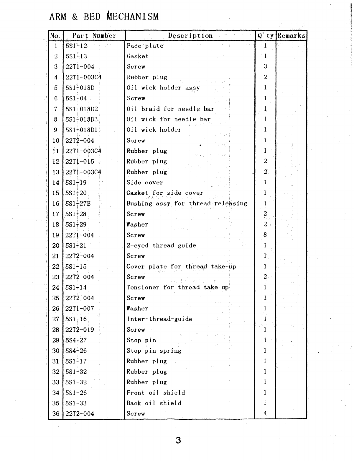
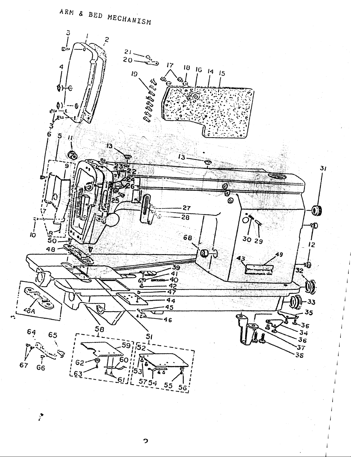
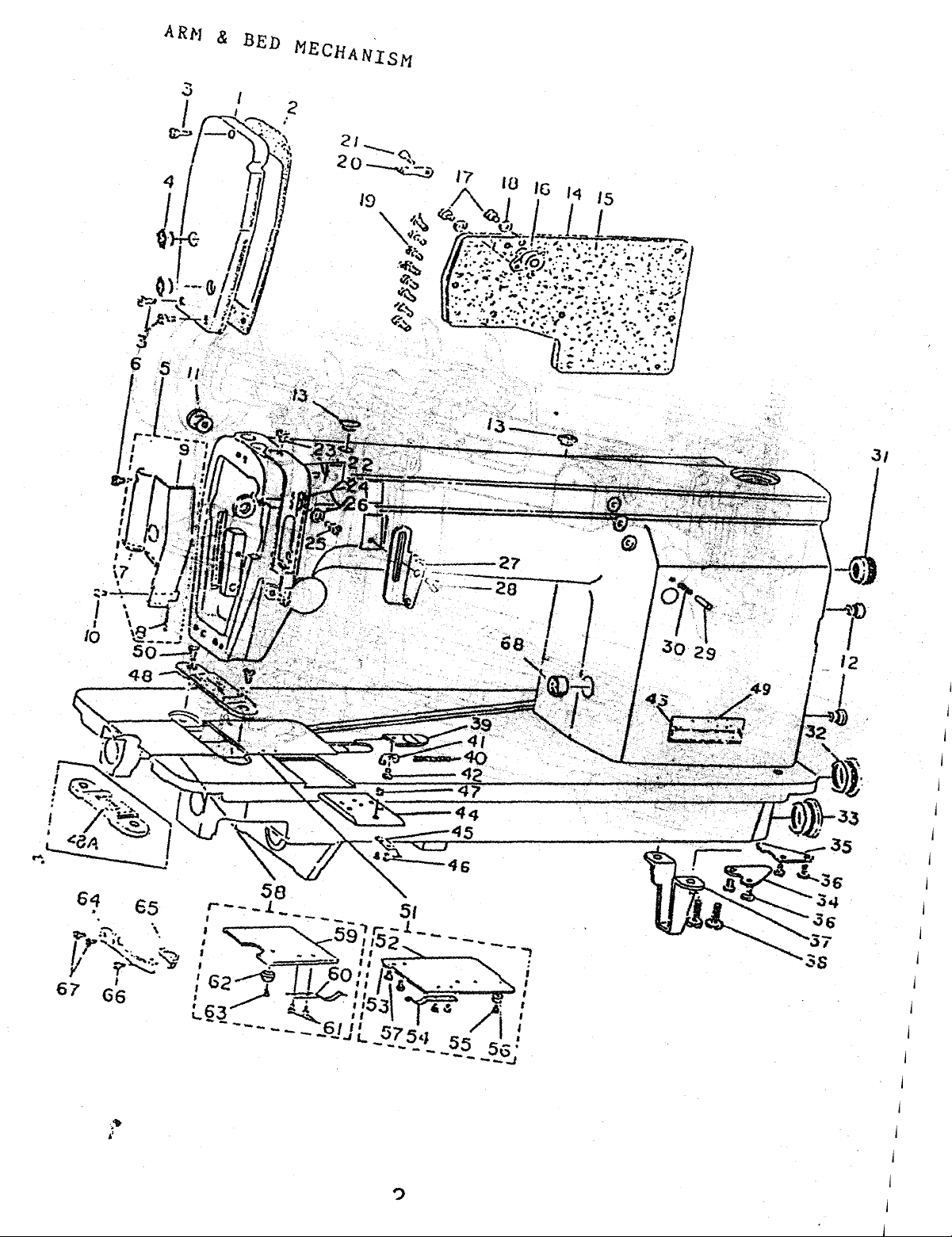
ARM
&
BED
MECHANISM
No.
1
2
Part
5SF12
5S1ll:3
3 22Tl-004
'
'·
22Tl-003C4
4
5S1i018D
5
6 5S1-04
5Sl-018D2
7
5Sl.:..018D3;
8
5S1..-018D1
9
10 2212-004
22Tl-0Q3Cl.l
11
22Tl-015
12
22Tl-003C4
13
;
14
5S1T19
l
.
.
15
16
17
5Sl;20
5S1f27E
5S1t28
l
'
Number
'
'
·
l
'
l
Face
plate
..
Description
Q'
Gasket 1
Screw
Rubber
Oil
plug
wick
holder
as.sy
Screw
Oi 1 braid
wick
Oil
wick
Oi
1
Screw
Rubber
Rubber
Rubber
Side
Gasket
plug
plug
plug
cover
for
,.-
Bushing
for
for
holder
side
assy
needle
needle
cover
for
thread
bar
bar
.
~
'
'
l
l
releasing
.
Screw
ty
1
3
2
1
1
1
1
1
1
1
2
2
1
1
1
2
Remarks
18
5Sl+29
19
22T1-004
20
5S1-21
2212-004
21
5S1-15
22
l
2212-004
23
5S1·d4
24
2212-004
25
22Tl-007
26
27
5S1T16
28
2212-019
29
5S4-r27
5S4.:26
30
6S1.:.17
31
5S1---32
32
33 5S1-32
5S1-26
34
Washer
Screw
2-eyed
thread
guide
Screw
Cover
plate
Screw 2
1ensioner
Screw
for
for
thread
thread
take-up
'
take...:.up;
l
;
Washer
Inter-thread-guide
'
Screw
Stop
Stop
pin
pin
Rubber
Rubber
Rubber
Front
plug
plug
plug
oil
'.
spring
shield
2
8
1
1
1
1
1
1
1
1
1
1
1
1
1
1
5S1..:.33
35
36 2212-004
Back
Screw
oil
shield
3
1
4
Page 6

Page 7
ARM
&
BED
MECHANISM
64
lt=>.,
~~
67 66
€5
.
-..
~
;t. ¥
\
r~-~
?
Page 8

Page 9
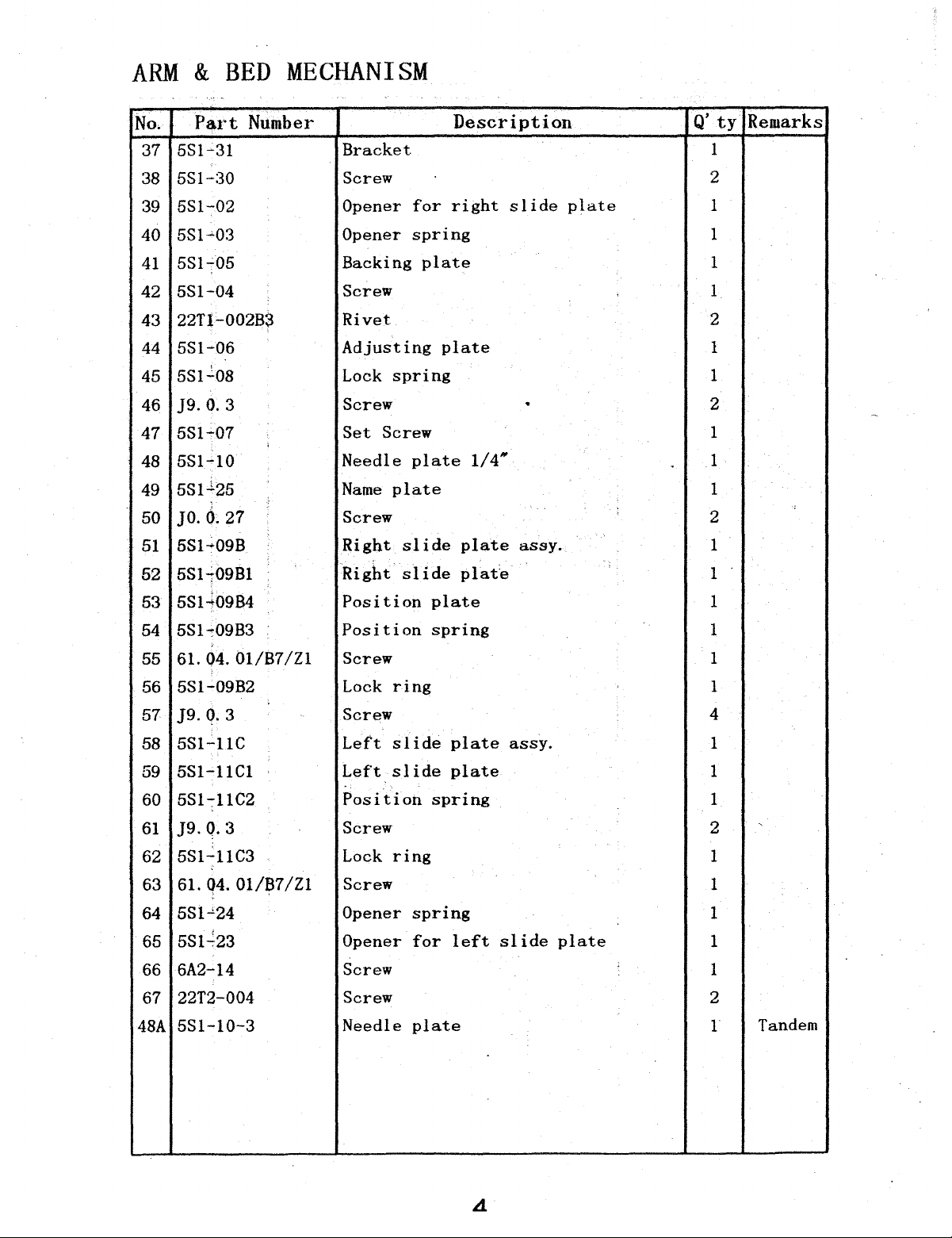
ARM
&
BED
MECHANISM
No.
5S1-31
37
5Sl-:30
38
5S1-02
39
5S1-'03
40
5st~o5
41
5S1-04
42
22Tl-002B3
43
5S1-06
44
5S1..:.08
45
]9.0.3
46
5S1-07
47
5S1-10
48
5Sl-l25
49
]0.0.27
50
5Sl~09B
51
5Sh09B1
52
5S1-l09B4
53
Part
Number
'
Description
Bracket
Screw
Opener
Opener
Backing
Screw
Rivet
Adjusting
Lock
Screw
Set
Needle
Name
Screw
Right
Right
Position
for
right
spring
plate
plate
spring
Screw 1
plate
plate
slide
. .
slide
plate
plat~
plate
slide
1/4"'
assy.
plate
.
Q'ty
1
2
1
1
1
1
2
1
1
2
1
1
2
1
1
1
Remarks
'
5S1-09B3
54
61. 04. 01/B7
55
5S1-09B2
56
57
J9.Q.3
5S1-11C
58
59
5Sl-11C1
60
5S1-:-11C2
J9.Q.3
61
5S1-11C3
62
61.
63
5S1...,24
64
5S1_:23
65
6A2-14
66
22T2-004
67
5S1-10-3
48A
04.
01/87
/Zl
/Z1
Position
Screw 1
Lock
Screw 4
Left
Left
Position
Screw 2
Lock
Screw
Opener
Opener
Screw
Screw
Needle
ring
slide
slide
ring
spring
for
plate
spring
plate
plate
spring
left
1
1
assy.
. 1
slide
plate
1
1
1
1
1
1
1
2
1
'
Tandem
Page 10

Page 11

r-------
'
-.
_____
_
--
,._-
6
zo
5
Page 12

Page 13
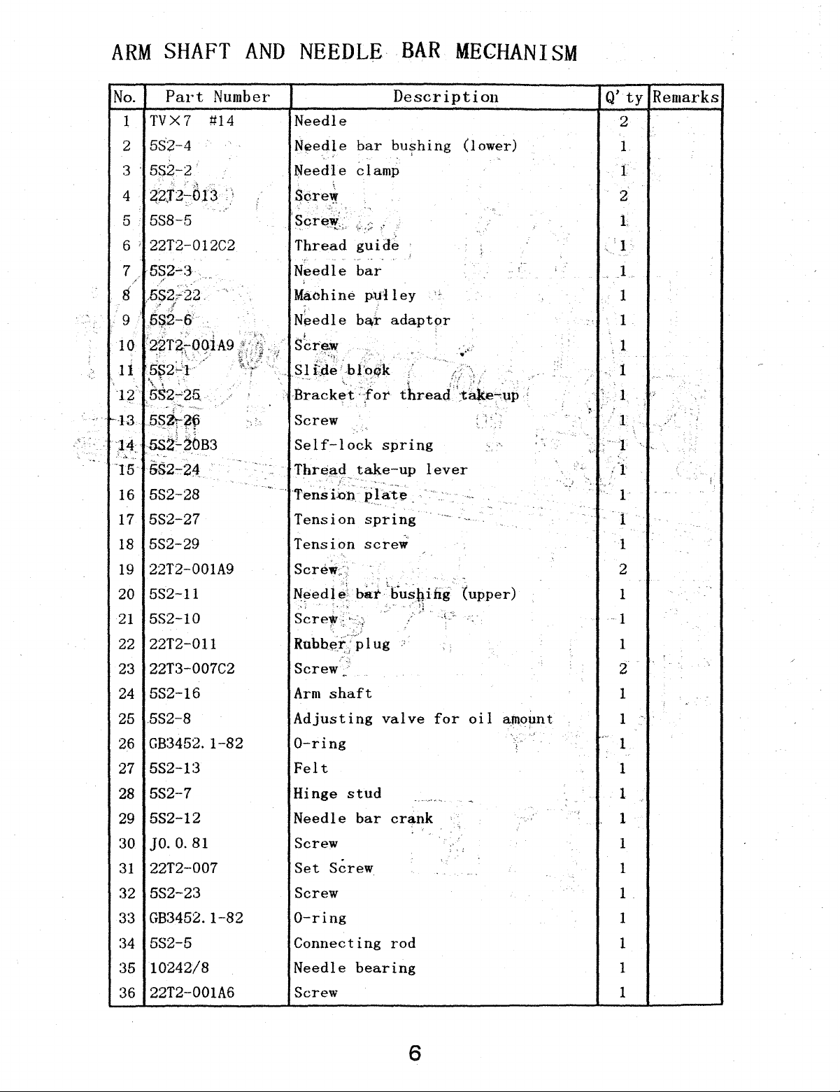
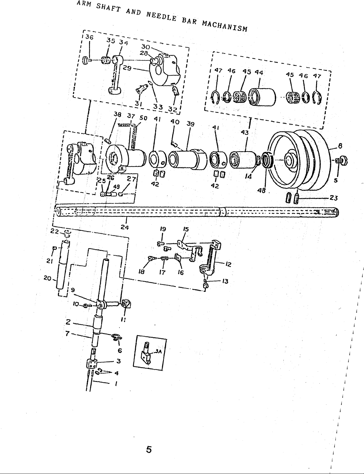
ARM
SHAFT
AND
NEEDLE
BAR
MECHANISM
No.
Part
Number
1 TVX7 #14
2
5S2-4
3
582-2
4
~2J2-;-th3
5S8-.5
5
6 ' 22T2-012C2
7
5S2-3
8 .5$27'22. .
" r
9
5~2-&'
1 o
22Ti-ooiA9
~;
~
', ' _,.
11
SS2;_:'J·
S,r
•"';-
,:
'\
~
'
T2·
_58~~-25,
13
s~ir?f
'14:
5SZL20B3
.·.::.
·15
6s2-24
16
582-28
17
5S2-27
•
~
/
•j
Description
Needle
Nfi)edle
Needle
bar
bu~hing
clamp
Sore~
Thread
Needle
Machine
N~edle
Sl
td~
Bracket
Screw
Self-lock
Thre13.d
Tension
guide
..
bar
pulley
b&r
·_.b
1 :oqk .
·;for
take-up
spring
adaptor
spring
Q'ty
Remarks
2
(lower)
1
1
2
l
1
1
-
,fi
,.
threacf':t<:t.ke-:~p
;
<,
lever
'
.
,
... · .1
~
1
1
' 1
1
1
1 '
;"J
1
1
;
I··,·
18
5S2-29
19 22T2-001A9
20
5S2-11
21
5S2-10
22 22T2-011
22T3-007C2
23
24
5S2-16
25
5S2-8
26 GB3452.
1-82
27 5S2-1:3
28
5S2-7
29
5S2-12
30
]0.
0.
81
31
22T2-007
32
5S2-23
33 GB3452.
34
5S2-5
1-82
Tension
screw
Screw::. .
Needle;
''
Screl!'
Screw
Arm
Adjusting
bar
.
-·
~
h.
·
shaft
Lbu~biiig
" q
valve
for
0-ring
Felt
Hinge
Needle
stud
bar
---•·••r-.
crank
Screw
Set
Screw
Screw
0-ring
Connecting
rod
{upper)
oil
-
. '
amount
l
2
1
1
1
2
1
.
1
.
...
1
1
1
.,
1
1
1
1
1
1
35
10242/8
36 22T2-001A6
Needle
Screw
bearing
6
1
1
Page 14

Page 15
,.._-
I
----.
__
_
----
-
~
-
8
'20
. I
5
Page 16

Page 17
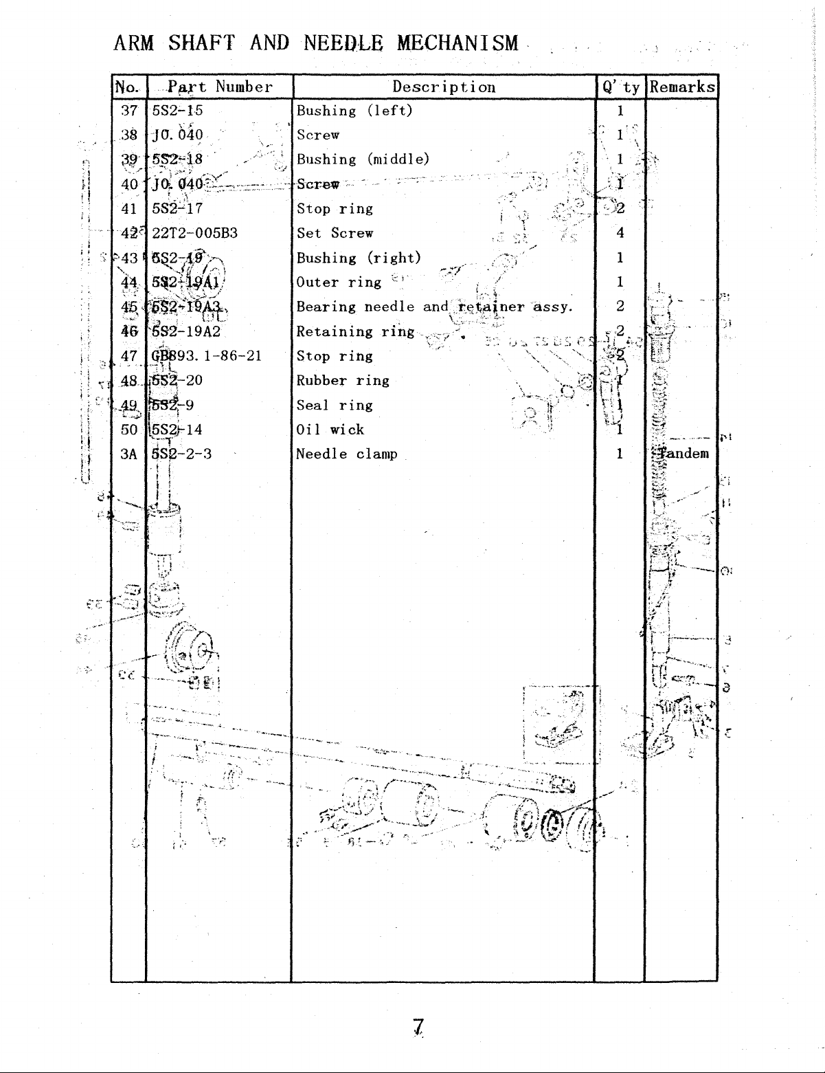
ARM
SHAFT
AND
NEEDLE
MECHANISM
No.
582;._15
37
.
:38
;3!}'
4'o-
41
i i
·
4~V
i
l '
:;
~·43
'·-.
44.
4_-~--'
-·
' -
46
\';;
:JO.
049
5S2":'l8
J~--~~o:t~;~,e-~:7:
582.:..;17
22T2-005B3
5~-{t9'>-\
.
~J.r·•
5:t21wA.l)
)@~~i~JU_-··
..
·~
LDL
SS2-19A2--
Number
..
'·
Bushing
(left)
Screw
Bushing (middle)
'"'
Scr~-·
Stop
Set
Bushing
Outer
Bearing
ring
Screw
(right)
ring
needle
Retaining
Stop
Rubber
Seal
Oil
ring
ring
ring
wick
Needle clamp
Description
'-::
i ·
ring
.,\. : j
'
'
~
Q'ty
";''
~
Remarks
4
1
)I
1
i ,
..
Page 18

Page 19
Page 20

Page 21
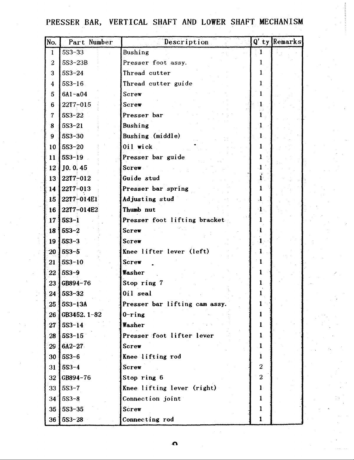
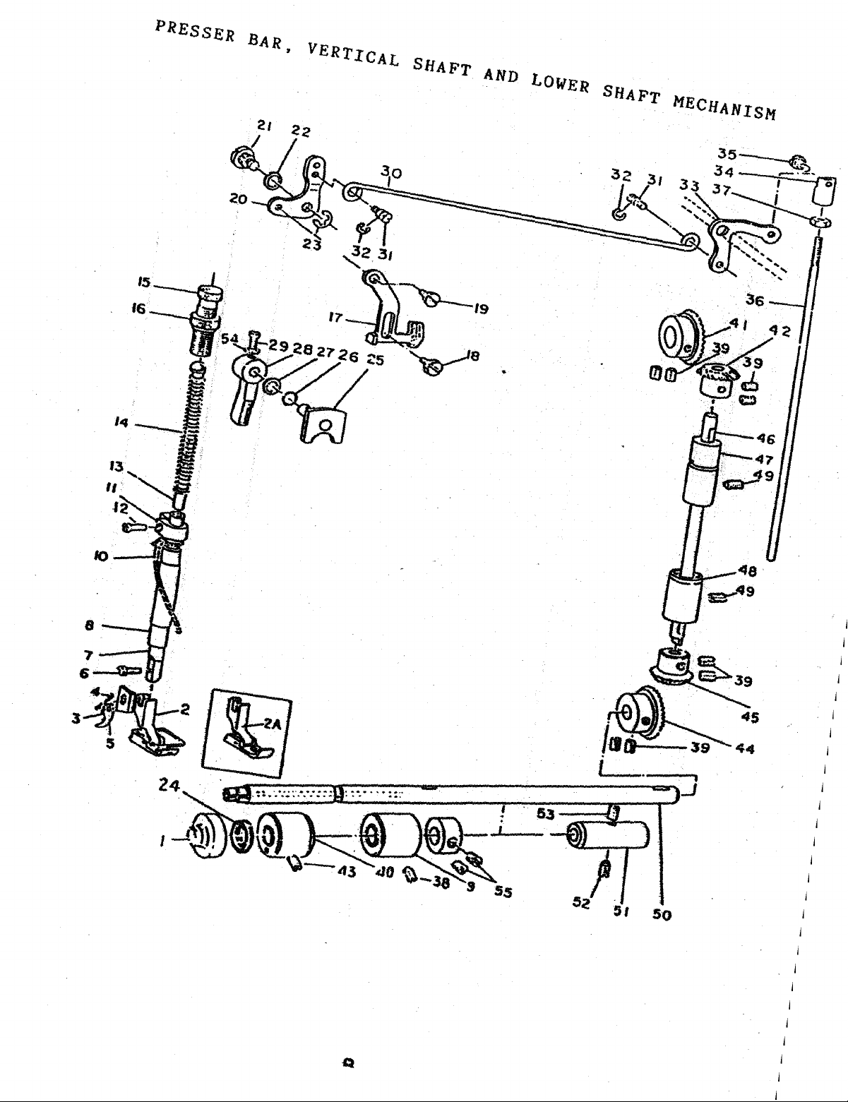
PRESSER
BAR,
VERTICAL
SHAFT
AND
LOWER
SHAFT
MECHANISM
No.
1
2
3
4
5
6
7
8
9
10
11
:12
13
.
14
15
16
17
18
19
20
21
.
22
23
24
Part
553-3:3 Bushing
5S3-2:3B
553-24 Thread
553-16
6A1-a04
22T7-015
553-22
553-21
5S3-30
553-20
553-19
J0.0.45
22T7:-012
22T7:013
22T7.-014E1
22T7-014E2
5S3-l
SS3-2
5S3-3
553-5
5S3-10
5S3-9
GB894-76
553-32
Number
·.
Description
Presser
Thread
Screw
Screw
Presser
Bushing 1
Bushing
Oil
Presser
Screw
Guide
Presser
Adjusting
Thwnb
Presser
Screw
Screw
Knee
Screw
lasher
Stop
Oil
foot
cutter
cutter
bar
wick
bar
stud
bar
nut
foot
lifter
.
ring
seal
assy.
guide
(middle)
guide
spring
stud
lifting
lever
7
.
bracket
(left)
Q'ty
'
.1
1
1
1
1
1
1
1
1
1
1
1 .
•
1
1
1
1
1
1
1
1
1
1
1
Remarks
5S3-l3A
25
GB.'3452.
26
5S3-14 Washer
27
5S3-15
28
6A2-27
29
553-6
:30
5S:3-4 Screw
:31
GB894-76
32
553-7
33
34-
553-8
553-35
35
36 6S3-28
1-82
Presser
0-ring
Presser
Screw
Knee 1 i
Stop
Knee
Connection
Screw
Connect-ing
bar
foot
ft
ing
ring
lifting
lifting
lifter
rod
6
lever
joint
rod
cam
assy.
lever
(right)
1
1
1
1
1
1
2
2
1
1
1
1
-
Page 22

Page 23

IS_---..;~.
16
-----r~..,
Q
Page 24

Page 25

PRESSER
BAR,.
VERT,ICAL
SJ:IJ\FT
AND
LpWER
fSHAFT
~ECIJANISM
.
1
22T21-002
38
:39
22T2+005B3:
j
140
!41
;42
l
143
!
m
1
!45
l
146
1
47
I
f48
J
'49
lso
;
'
151
t
;s2
~53
!
Js4
Iss
1
·i2A
I
1
. i
5S:3-:31
22T3t010E2~1
t {
22T:3f010E2~2
i t i
22T2f00f
22T:Ho 1
~
22T3~01pE2~1
' '
5S3-}8
5S~3-:
t 1
5S3~t7
22T2lOO?
SS3-
SS3-t6
22T2t002
5S3-t7
5S3-
22T2iO~~B3l
SS3-:;l3BT:3
4 ·
1 •
2 ; I
l i
I .
I ,
l
. I
!
j
OE2it-1
. i
l
I
I
J
;
I
'I
'
I
'
'
: ,
f
Screw
Screw
Set
Bushing
Bevel
Bevel
(l~:ft)
gear
gear
Screw
Bevel
Bevel
Vertical
Bushing
gear
gear
shaft
(uppc:rr)
.
Bushing (lower)
Screw
Lower
Bushing
shaf~,,
:
....
1
(right~,~~,
Screw
F:el~t
,,
.
Washer
Set
Screw
Presserr; float
• •
_1
~-:
' • 4
.•
~ssy.
'1
.
'•
....
1
8
1
1
.1:
i
• >
·-\
•
~
l l
;
:,-•l
:
:'
' '
~
~;
: \
. '
'
..
..
. I
: "1
-~
' -
~
~
..
.,., . ! !
i : j
1
1
1
1
1
1
2.
.
''
l
-·
. j
l
~
~
i t :
i
' .
I
.J:·
l
",
;,
. !
1
1
·
..
'·td
i
,-_
.•
'.
l
i
_,;:._, . .vI
. '
'
.
.._
,:
i
; !
; :
..
i
!
. i
'
~
'
i.:
I
.!
·.-'l?
'
...
~
f
:
j
l
.
2
1
Tan8elll
. .
~
. !
i
~
' . !
...
·;
.,
i
•1
..
l .
·i ,
-I
.
~
.
-·:
I
-. I
•
~..,;
1!
• •
.
- l L
i
·._
--l
.
~
1.fl
. .
i
i
!
. i
'I
i
'·
.i
..
..
I
i
i
l
l
Page 26

Page 27

ss
sa
53
27
11
Page 28

Page 29

STITCH
No.
1
2
Part
5S4-28
5S4-:30
REGULATING
Number
Dial
Screw
MECHANISM
Description
Q'
1
1
t
y
Remarks
5S4-29Kl
3
GB1235
4
5S4-11D2
5
5S4-12
6
22T2-002 Screw
7
5S4-14
8
5S4-13
9
5S4-11Dl Screw
10
5S4-11D2 Screw
11
5S4-18G Feed
12
5S4-18G6
13
5S4-18Gl Screw 3
14
5S4-18G4 Screw
16
16
584-20
17
9241/23
5S4-231 Lever
18
5S4-15E2
19
Regulating
0-ring
Stitch
Pin
Stitch
Pin
cam
Screw
Feed
Be1:1ring
..
Front
connection
shaft
crank
screw
regulating
regulator
assy.
block
link
..
rod
.
1
1
1
1
1
1
1
1
1
1
2
2
1
1
1
1
5S4-15E1
20
61-04-01/B3
21
5S4-15E3 Screw
22
2:3
5S4-24 Screw
5S4-16
24
5S4-46
25
5S4-47 Hanger
26
5S4-48 Screw
27
21T3-003
28
29
5S4-32M2
5S4.,.55Tl
30
5S4-32M1
31
5S4-04C2 Screw
32
5S4-54
33
5S4-51
34
35
5S4-48 Screw
36
5S4-54 Long
Screw,
Serew 1
Pin
Spring
1
1
2
1
1
1
.
1
Screw
Stopper
Crank. 1
Rubber
Long
Short
bushing
ring
pin
p1n
pin
1
1
1
2
1
1
1
\
1,
12
Page 30

Page 31

27
3,1.~
2.9~.~·
·_U
4~8J-
..
,r~
57 I
sb~
I
11
Page 32

Page 33

STITCH
No.
:37
Part
]0.081
REGULATING
MECHANISM
Number
Screw
Description
Q'
ty
1
Remarks
5S4-53
38
5S4-52
39
40 22T6-008D3
5S4-45R1
41
61-04-01/B5
42
5S4-49
43
5S4-42
44
5S4-43
45
5S4~22
46
47
5S4.-21H2
5S4~32M3
48
5S4'-21H3 Nut
49
5S4-21H1
50
.51
5S4-15E1
..
'.,;
.·
q2.
61-04-0l/B3.
53-
5S4-31L3
5S4-31L2
54
Feed
Pin
Screw
Feed
Screw
Feed
Pin
Nut
Pull
Pin
Screw
Back
SCrew
'
Screw
Lever
Screw
driving
crank
rocker
bar
bar
crank
rock
arm
.
·.
1
1
1
1
1
1
1
1
1
1
1
1
1
1
1
1
1
5S4-31Ll
55
GB1235
56
57
5S4-.33
GB95
58
5S4-34
59
5S4-18G2
60
5S4-;-l8G5
61
5S4-18G:3
62
Screw
..
0-ring
Nut
Washer
Washer
Small
Big
Feed
10
spacer
spacer
cam
1
1
'
1
1
1
, .
. .
1
1
1
13
Page 34

Page 35

'
14
Page 36

Page 37

FEED
No.
1
Pait
5S4-07
&
FEED
N4mber
LIFTING
.
Feed
dog
MECHANISM
Description
'>
,
Q',ty,
Remarks
1
5S4-08
2
:3
5S4-09
5S4-08
4
;'C"
A
()<")
uv--·l
5
5S4-21H:3
6
'7
6Al-08
I
5S4-:37P1
8
5S4~37P2
9
, 10
5S4-06
5S4-:05
11
5S4-36N2 Crank 1
12
5S4-36N1
1:3
14
GB894
15
5S4-50S1
5S4-:-35
16
17
5S4-43
18
5S4-25j1
'
Washer
Screw
Washer
J:<'eed
bar
Nut
Screw 2
1
shaft
wick
.
Crank
Oi
Washer 1
Screw
Screw
Stop
Feed
Front
ring
rock
15
shaft
bushing
Nut 1
Narrow
collar
1
1
1
1
1
1
1
1
1
1
1
1
1
'
I
'
]0.068
19
5S4-40Q1
20
22T2-00B2 Screw 2
21
5S4-5S2
22
2:3
5S4-44
]0.081
24
5S4-:39
25
5S4-10
26
5S4-01A1 Feed
27
28
29
:30
:31
32
:n
34
35
5S4:-01A2
5S4-0:3B1
5S4-04C1
5S4-04C2
5S4-03B2
5S4-10
]0.
040
5S4-38
!
Screw
Stop
Oi
Back
ring
wick
1
bushing
Screw
Feed
1 i
Front
I
Screw
Feed 1 i
Stop
ring
Screw
Oi
I wiek
Front
Screw
wick
Oi
I
fting
bushing
i
fting
ft i ng
bushing
rock
crank
1
ink
shaft
(left)
2
1
1
1
1
1
1
1
2
1
1
2
1
1
1
1
36 5S4-40Q1
Stop
ring
1
Page 38

Page 39

-------
35
,.____
25
------
-----------
---
----
14
Page 40

Page 41

FEED
No.
:37
Part
22T3-002B2
&
FEED
Number
LIFTING
Screw
MECHANISM
Description
Q'
ty
2
Remarks
:38
5S4-44
:39
JO.
081
40
5S4-17F1 Feed
61-04-01/BS Screw
41
42
5S4-19
4:3
9241/24
5S4-42
44
1A
5S4-07-3
Back
Screw
Feed
Bearing
Pin
Feed dog
bushing
lifting
lifting
crank
connecting
(right)
.
rod
1
1
1
1
1
1
1
Tandem
1
.
.
16
Page 42

Page 43

17
Page 44

Page 45

LOOPER
MECHANISM
No.
1
2
:3
4
5
6 JO.O.
7
8
9
10
11
12
13
Part
Number
5S5-01
5S5-02
5S5-:30
5S5-:31
5S5-28
71
61-04-01/{3:3 Screw·
5S5-29
5S5-04
61-04-01/B4/Zl
GB894-2-86
5S5-03A
6A2-2:3
14
5S5-07
15
5S5-05B
16
..
17
5S5-05B2 Screw
Looper
Screw
Left
looper
Right
Left
1 ooper
Screw
Right
looper
Bushi[lg
Screw
Stop
Half
ring
shaft
Screw
Yarn
Cross
braid
joint
Looper
base
looper
assy.
crank
Description
bracket
bracket
.
housing
assy.
. '
Q'
ty
Remarks
1
4
1
1
1
2
2'
.
...
.'
1
2
2
. 1
I.
.
4·
1
.''
..
1
1
:3
:22T
18
l-00~3C4
19.
20
5S5-08 Bushing
5S5-09
21
6A6-08A
22
5S5-10
23
5S5-11
24
25
5S5-12
61-04-01/B9
26
5S5-13
27
28
5S5-14
6A6-08A
29
5S5-20
30
6A6-08A
31
5S5-19
32
3:3
6A6-08A
5A5-18
34
Rubber
Oi
Looper
plug
returning
1
crank
Screw
Eccentric
Looper
Front
driving
bushing
Screw
Back
bushing
Collar
Screw
Left
turn
Screw
Right
turn
Screw
Needle
protecting
stud
gear
gear
pipe
shaft
cam
1
1
')
..
1
2
1
1
1
2
1
1
2
1
2
1
2
1
35
36
6A6-08A
5S5-17
Screw
Needle
protecting
crank
18
2
1
Page 46

I
I
I
I
I
I
I
I
Page 47

17
Page 48

Page 49

LOOPER
MECHANISM
No.
:37
38
Part
61-04-01/B4/Zl
5S5-16
39
!3SG-i:5;
40
Number
Description
Screw
'Pin
Yarn-braid
Fork-crank
Ne~<:U
~~~~-·-frr·a
Bushing
Screw
e:"'
pr'otect
i d · · .
"(
:·
l ·.
~
i ng
shaft
"'~
..
"'-
-...::.
(_.:·s
/
'
•..
...
Q'ty
Remarl\~
1
1
1 .
1
rc
1
..
J.~-~·-
1
' 1
~
1
·,,
.>
·
1
.
-2
·'
.
\.:
l.
__
.:,.
..
. \
"-
1
1
Tandem
1
Tandem
1
·'
·'
,L
19
Page 50

Page 51

THREAD
TENSION
MECHANISM
Page 52

Page 53

THREAD
TENSION
MECHANISM
No.
1 5S6-01A
2 5S6-01A8
:3
4 5S6-01A7
5 5S6-01A5
6
7 GB879-86
8
9 5S6-0tA:3
10
11
12
13
14
15
16
17 G83452.
Part
5S6-01A6
5S6-01Al
5S6-01A4al
5S6-01A2
:36T5-008E5
5S6-02
6A3...,18
5S6-03Bl
5S6~0382,
556-0383
Number
B4
1-82
Rear
thread
Tension
Tension
Retaining
Tension
Tension
Pin
Eyed
thread
:3-eyed
Installation
Screw
Thread
Screw
Thread
Thread
Nut
·
0-ring
Description
tension
nut
spring
ring
disc
stud
guide
thread
plate.
releasing
releasing
releasing
plate
guide
cam
stud
pin
assy.
plate
(rear)
{rear)
(rear)
(rear)
Q'
ty
1
2
2
2
4
2
2
2
2
1
2
1
1
1
1
1
l
Remarks
18
5S6-04C2
19 36T5-008E5H01
20
556-15
21
556-14
22
22Tl-004
23
5S6-05
24 G83452. 1
25
5S6-10
26
5S6-06
27
5S6-08
28 556-1:30
29 5S6-01A2
:30
5S6-t:301
at
5S6-1 :m2
:32
5S6-01A1
:3:3
5S6-1
:34
5S6-1
~82
:30:3
:304
Thread
Screw
Spring
Suspension
·screw
Shaft
0-ring
Bttshing
Bushing
Bushing
·
Front
thread
Installation
:3-eyed
Thread
Tension
Tension
Tension
releasing
lever
tension
plate
thread
guide
plate
stud
disc
spring
fork
guide
cap
assy.
plate
(front)
1
1
1
1
2
1
1
1
1
t·
1
1
2
2
2
4
2
:35
36
5S6-l:3D6
5S6-1:3D5
Tension
Retaining
spring
ring
?1
2
Page 54

I
I
I
I
I
I
I
I
I
I
I
I
Page 55

THREAD
TENSION
MECHANISM
Page 56

Page 57

THREAD
TENSION
MECHANlSM
. ! .
No.
:37
:38
39
40
41
42
43
44
45
46
47
48
49
50
51
52
5:3
54
55
56
57
58
59
60
61
62
63
64
65
66
P&rt,
5SEF·J
5S6.Jog
5S6-!07
586-,11
5S6-il2
6A3-li8
5Sl-i21
5S6-1I
5S6-H
5S6i18
5S6-h1F
5S6-!21F9
5S6~21F7
5S6f!F8
5S6
6A2
GB9i 2-.85 j
5S6inru·
5S6i21F8
5s6-{2If16
5s6-f2Ifl3
SS6t3B3
5S6
5S6f1F~5
5S6~1F1
5S6 . 1}11
22Tt004
N3-
5S6-bOE
5S6-1!9
__
,_
:3b7a·:·
'
i
!
6
j
7.
l
l
..
l
!
1F10 I
114
IR4
I ,
.
~
t 27
i
I
!
;
j
!
. f
i
i
~
I
.
..
Niijnber
'
i
'
i
I
I
i
'
i
'
l
i
1
i
l
i
i
'
i
l
. J
I
I
; I
J
'
l
'
t
I
I
!
f
I
~
l
l
l
l
.
j
I
I
l
'
i
'
'
l
. i
.
!
~
.
'
.
t
;
.
. - .
,
;_.;;.
...
.•.
;
..
~
-·\·-
'I
l
i
I
'
'
< ' ' ;
~
assf.
'
~
r 1
I
;
:
. , !
I
'
•'
;
~
t
~-; / ~
I
,
,.,
--~--
;
'
'
~
;
:
i
l
..
I
i
;
'
e
Descr-iption
. .
iei1.S'ion
nut
.......
Screw
Serew
Spring
Thread
stop
releasing
Screw
2-eyed
Threaq.g~~d,~
thread
Screw 1
Thread
Thread
Th1;~~d·
'
Thread
Sqr~w
Spt;'ii1g·
guide
.
releasing
g1,1.i
de
'•·'
guide
:0<
:
l;':
,
..
Screw
Washer
Spring
3A
plate,
Screw
....,
ri,ng
cam
guide
bed
at
...
'·
'
.t,rough.
bracket
plt.l
te,
.. l - •
plate
;.
••
·~.~
>
.
(front}:
(pi,g)
(small)
i.
Spring
!
;
;.
"
l
t
I
.
.·
. i
J'
J
'
!
l
l
'
~
. '
. '
;
!
~-
;·
dower)
i
l-
Screw
Nut
Thread
Thread
Thread
Bushing
Screw
Screw
Thread
.Screw
j'
retaining
guide
guide
(right)
(left)
:"j
releasing
,,
plate
~·-
~
\.
cam
: . l t .• ..
'
.,
~
'
assy.
'
i
..
.
-
.....
..
.
..
~
-
..
-Q~'
ty
;
-·!
,. .
...
. -
Remark~
2
_
...
-
1
1
1
1
1
l
,1
1
. '
. . . .
~
l
1.
1
J·
,
L
'
'.?:·
2
~
'
'
'
~
;
.
. '
'
l
.
i
j
\
'
I
(
~
~
'
1
,
, .
..
~
.
~·.
~
i
i
!
.,
- i
,.
,
. f
'
,
..
l
'
l'
..
. ,
• ?
!
1
'1
1
1
1
1
1
2
1
2·
1
1
..
f
!
..
··;·
.
'
..
t
..
.
f
...
.
., !
. ,
..
i
.,
-
t
-
'
'
:
..
i
_.
l
!
i
.
s
!
,.
..
,.2.
,
l
!
i
.
I
I
l
;
...
,
. .
--
........
..
__
,-
--···
...,_
. .. -
22
Page 58

Page 59

23
I
4-•8 i
Page 60

Page 61

LUBRICATION
MECHANISM
..
No.
1
2
3
4
5
6
7
8
9
10
li
1?
i3
Part
5S7-01A:3,
587-05
5S7-01A2
36T5-008E5
5S7-09
5S7-08
5S7-06
5S7-07
5S7-10A Oil
5S7-10
5S7-17E1.
5S7-17E2 Bush
---~
·ss7:.:.13
Number
A4
.,
Description
Felt
Spring
Oi
1
sucking
tube
support
Screw
Pin
Spring
Joint
oil
sleeve
sleeve
tube
Oi
1
Main
tube
tube
Nut 1
.
-,,
...
Bushiltg
.
557-'14
H
557-22
l5
5S7-18.
16 r
5S7-23
17
18
2218-004 Screw 3
'19
5S7-21
5S7-20
20
I
21
5S7-02
5S7-04
22
36f5-008E5
23
24
25
._
-.
ssr-o4··
' ' '
•'
~.
36T5-008E5
..
':\
·~
:
'
,.
.,
'"!
Scr~w.
oil
·
..
JJ!lpe
Oi
I
Oil
Oil
Oil
tube
Screw
, .
Tube
Screw
pQ.,l,P
I
ler
pump
pump
pump
tube
claiUP
clamp
"
screen
cover
fitting
screen
·•
brackeJ,
plate
'
..
..
. I
I
Q'
·.·
1
1
1
1
1
1
2
1
1
1
1
3
3
1
1
'1
1
1 '
1
1
1
1
ty
;.
•',.'
Remarks
'
·l
~
~
"
587-'0382
io
5S7.,..03Bl
27
,.
28·
J5S7-19
i-~·
557..,-16
.;?9
:30
5S7-15DI
6I-04-0l/B4/E1
31
5S7-12C
32
33
6A4-007B
5S7-11
34
35
22Tl-008H
'.
.,
Joint
OiL
tube
pump
Oil
Bushing
Collar
Screw
Collar
Screw
pump
Oil
Oi
1 check
(big)
(small)
shaft
window
.
assy.
24
...
1
'
1
-
1
1
1
2.
1
2
1
1
,•
Page 62

Page 63

Page 64

Page 65

OIL
No.
PAN
Part
1 22T9-010
MECHANISM
Number
Rubber
cushion
Description
(small)
Q
'ty
2
R k
emar s
2 GB894-76
3
5S8;-1
4 5S8-2
5 5S8-7
6
221'9-o·og
.
·""1
·5SB'"'5 · ..
,
L.
·8
GB3452.
9
GB95~85
10
5S~-3
11
22T9-003B3
·'-~7',--
12
22t9-003B4
1
:3
~~1'9:-::'00386
1-82
Stop
Oil
Gasket
Gasket
Rubber
-~-
Screw
""7
-
.
o:::..rlng
; Washer 10
...
'1
·•·
Hinge
joint
.
Screw.
·.
BeU
• ~ ' ! : ' ' ' '
·
!spFing
Knee n
Screw
17 22T9-001A9
18
22T9-001A10
Adjusting
Nut
ring
pan
'··-·
·-
~
crank
bar
;::
11
(A)
(B)
cushion
-.
.
fter·-siop
screw
(big)
..
bradk~t·
'; ~ ' . ' : '
"'
1}.,>
. .
.'
1
:bracket
·;
1
1
2
1
.2
·"'"-·
..
',:.,_c~~'-1·
.
·;To,·
,J
-':":
'
:c:a
·2
..
l
,
..
;:
f
1
I
2
.
·
1
1
1
1
2
2
19
22T9-003B2
22T9-003B8
20
22T9-003B5
21
22T9-003B7
22
22T9-003B1
23
5S8:.:...4
24
''-',
.
-
J
Bell
Pad
.
~
1\f\e~
crank
.
press
s~:t~w
Lifting
:r.od
Magnet
..
plate
1
1
.
1
1
1
1
-·
"
.•
26
Page 66

I
I
I
I
I
I
I
I
Page 67

BELT
GUARD & HEMMER
DEVICE
4\
5
,~,
1
CJ
~
.....
~
~.
l
,
3
9
,II
A
6
~)
,.,-,
Page 68

Page 69

BELT
GUARD
&
HEMMER
DEVICE
No.
5Sl0-l
I
5S10-2
2
SSl0-:3
:3
:'
4
?2T5-0IOD4
'
GB848~85
5
22T2-,004
6
r
~:c
''22Jt-o
8
5Sl0-'4
'9
5Sll
Part
Number
,,•·
19
J3el t cover
Belt
Be
Set
Washe'r
Screw
Screw
Stud
H~mmer
f
'
~o~er
It
cover
screw
.;·
-·
l/4n
Des~r
(big)
(middle)
(small)
~pt
ion
Q'
ty
1
1
1
1
1
7
1
Remarks
·.
··-'
,'··
28
Page 70

I
I
I
I
I
I
I
I
I
I
I
Page 71

Consolidated Sewing Machine
C~rp.
MAIN OFFICE
131
West 25th Street
New
York,
Tel: (212) 741-7788
Fax: (212) 741-7787
NY
10001
BRANCH OFFICE
7855
NW
29th Street,
Miami,
Tel: (305)
Fax: (305) 471-0243
FL
Bay
33122
471-0200
166
Page 72

I
I
I
I
 Loading...