

Consew 318RK-2 User Manual
DNSE
CONSOLIDATED SEWING MACHINE CORP.
I INDUSTRIAL SEWING & CUTTING EQUIPMENT
OPERATING
INSTRUCTIONS
&
PARTS LIST
31SRK-2
'----
INDUSTRIAL
400 VETERANS BLVD, CARLSTADT,
SEWING
&
CUTTING
EQUIPMENT
NJ
07072

~'*_:·N_O_T_E_(F_ig_.1_)
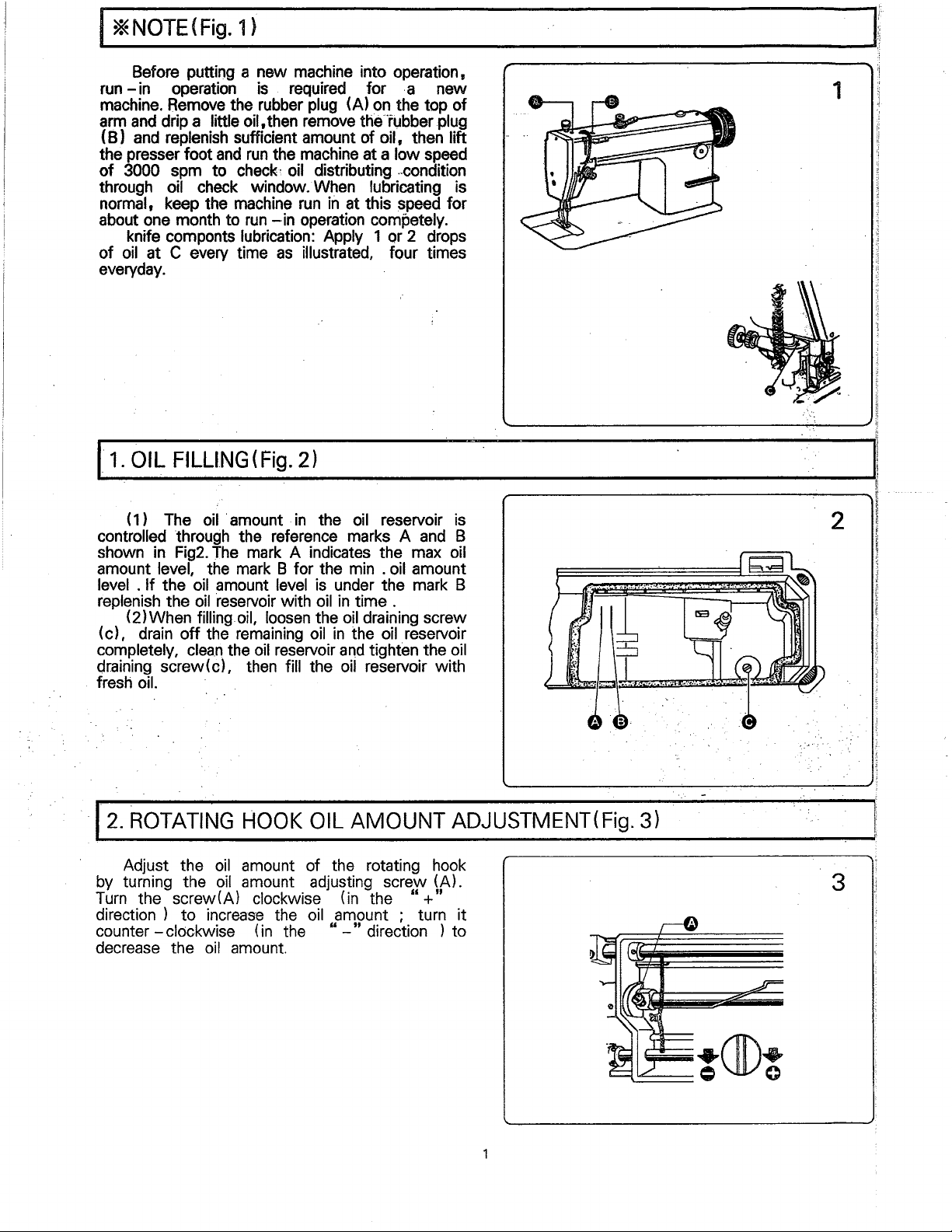
Before putting a new machine into operation,
run
-in
operation
machine.
arm
(B)
the presser foot
of
through
normal, keep the machine
about one month to
of
everyday.
11.
controlled through the reference marks A
shown
amount level, the
level .
replenish the
(c), drain
completely,
draining screw(c), then fill the
. fresh oil.
Remove
and
drip a little oil,then remove the··rubber plug
and
replenish sufficient amount of oil, then lift
3000 spm to
oil check window. When lubricating is
knife componts lubrication: Apply 1 or 2 drops
oil
at C every time
OIL
FILLING
( 1 ) The
in
If
(2)When filling.oil,
Fig2.
the
oil
oil
off
clean
oil
The
the
__________________________________
is
required for
the rubber plug (A)
and
run
the machine at a low speed
check~
·amount .
mark
amount level
·reservoir
remaining
the
oil distributing
run
in
run
-in
operation competely.
as
illustrated, four times
(Fig.
2)
in
the
mark
A indicates the max
B for the min . oil amount
is
with
oil
loosen
oil
the
oil
reservoir
at this speed for
oil
under the mark B
in
time .
oil
in
the oil reservoir
and
oil
.a
new
on
the top
..
condition
reservoir
draining screw
tighten the
reservoir with
and
of
1s
B
oil
oil
--------------~---[
~11
1
II
~
.
~
fl
2
f.
l
ij
~
12.
ROTATING
Adjust the
by turning the
Turn
the screw(A) clockwise (in the
direction ) to
counter
decrease the
-clockwise (in the "
HOOK
oil
amount of the rotating hook
oil
amount adjusting screw (A).
increas·e
oil
the
amount.
OIL
AMOUNT
oil
amount ; turn it
-"
direction ) to
ADJUSTMENT(
"+"
Fig.
3)
-.:-···-:·
.
3
:.
13.
OIL
PUMP
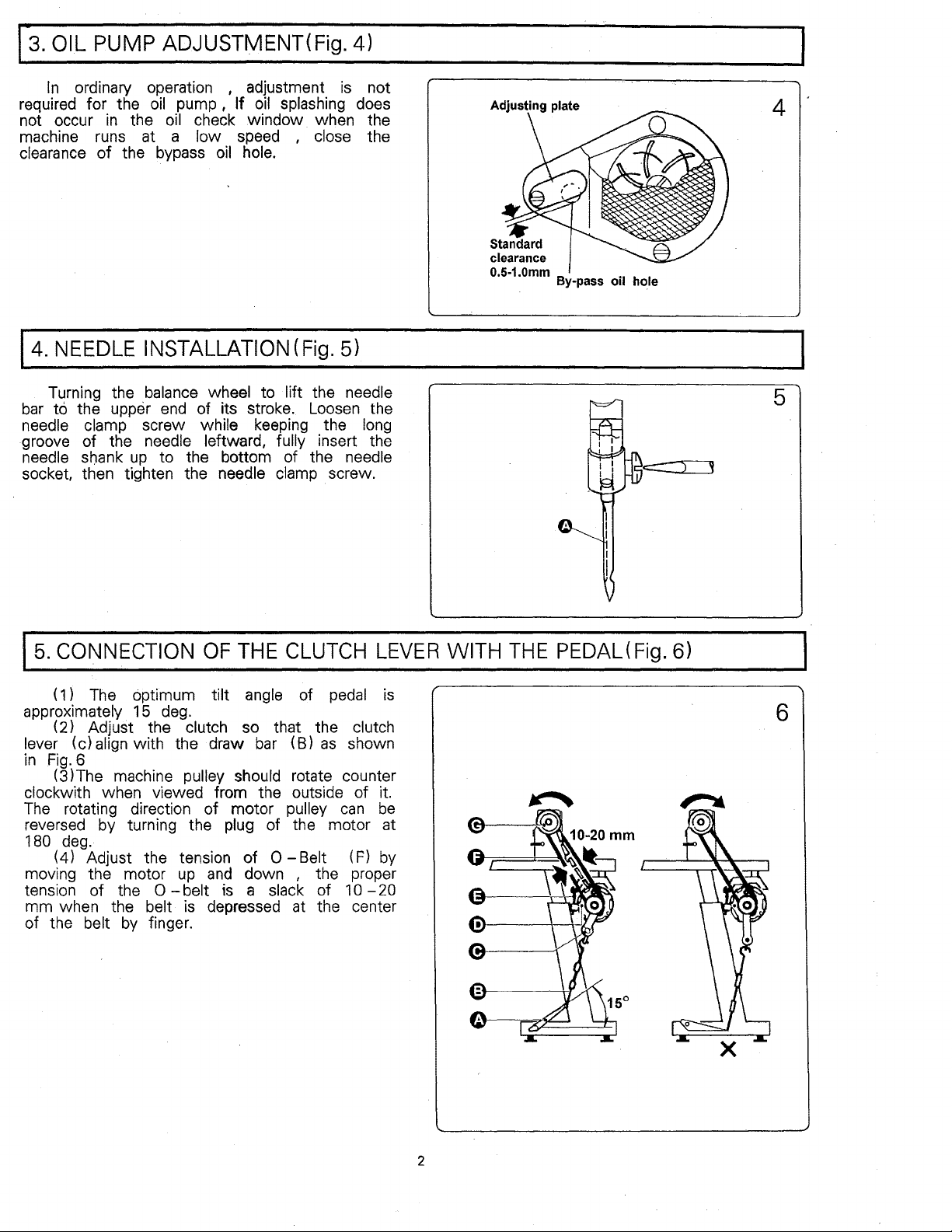
In
ordinary operation , adjustment
required for the
not occur
machine runs at a
clearance
14.
NEEDLE
in
of
ADJUSTMENT(
oil
the
oil
the bypass
INSTALLATION(Fig.
Fig.
is
pump,
If
oil
splashing does
check .window when the
low speed , close the
oil
hole.
5)
4)
not
Standard
clearance
0.5-1.0mm .
By-pass
011
4
ho.le
Turning the
bar
to the upper
needle clamp screw while keeping the long
groove of the needle leftward,
needle shank
socket, then tighten the needle clamp . screw.
15.
CONNECTION
( 1 )
The
approximately 15
(
2)
Adjust the clutch so that the clutch
lever (c)
in
Fig.
clockwith when viewed from the outside of
The
reversed by turning the plug of the motor at
180
moving the motor
tension of the
mm when the belt
of the belt
align
6
(3)The machine pulley should rotate counter
rotating direction of motor pulley
deg.
(4) Adjust the tension
balance
up
to the bottom of the needle
optimum tilt angle of
with the draw
0
by
finger.
wheel to lift the needle
end
of its stroke. Loosen the
fully insert the
OF
THE
deg.
up
and
-belt
is a slack of 1 0
is
depressed at the center
CLUTCH
bar
(B)
of
0-
Belt (F)
down , the proper
pedal
as
can
LEVER
shown
it.
be
by
-20
is
WITH
THE
PEDAL(
Fig.
5
) ,
6)
6
2
16.
BELT
COVER
INSTALLATION(Fig.
7)
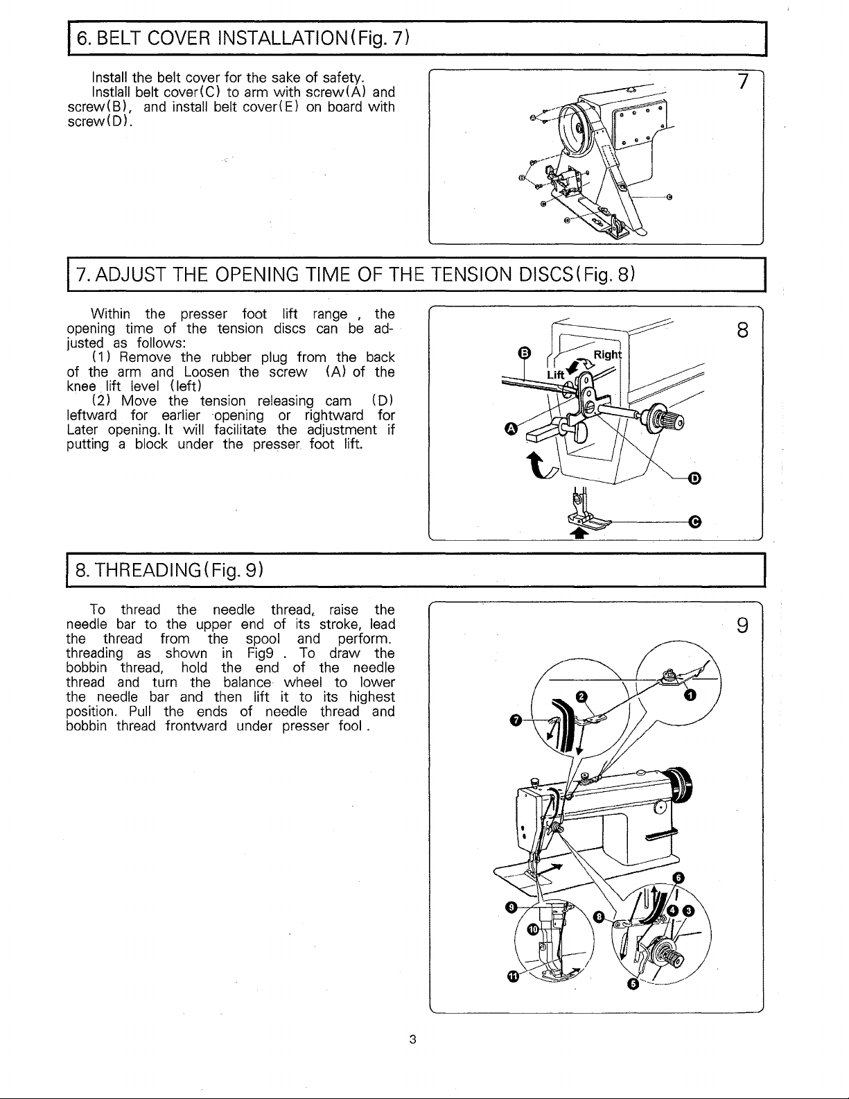
Install the belt cover for the
lnstlall belt cover(C) to
screw( B),
screw(D).
17.
ADJUST
Within the presser foot lift
opening time of the tension discs
justed
( 1) Remove the rubber plug from the back
of the
knee
· (2) Move the tension releasing
leftward for earlier
Later opening.
putting a block under the presser foot lift.
and
install belt cover(
THE
as
follows:
arm
and
Loosen
lift level (left)
It will facilitate the adjustment if
OPENING
·opening or rightward for
sake
of safety.
arm
with screw(A)
E)
on
board
TIME
range
can
be
the screw (A) of the
cam
and
with
OF
, the
ad-
(D)
THE
TENSION
DISCS(Fig.
7
8)
8
Is.
THREADING
To
thread the needle
needle
the thread from the spool
threading
bobbin thread, hold the end of the needle
thread
the needle
position.
bobbin thread frontward under presser fool .
bar
to the upper
as
and
turn the
bar
Pull
(Fig.
9l
thread,.
end
of its stroke,
shown
and
the ends of needle thread
in
Fig9 . To
balance·
then lift it to its highest
wheel to lower
and
raise
perform.
draw the
the
lead
and
9
3
19.
WINDING
The
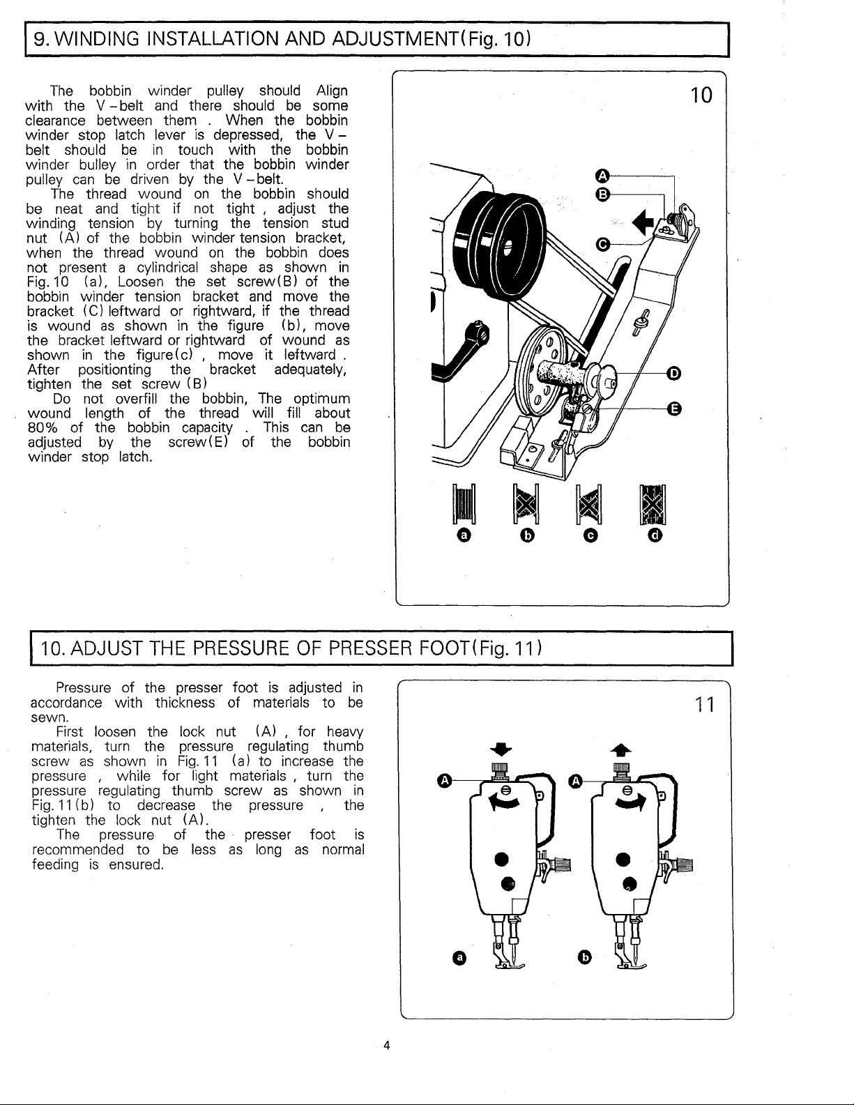
bobbin winder pulley should Align
with the V
clearance between them . When the bobbin
winder stop latch lever
belt should
winder
pulley
be
winding tension
nut (A) of the bobbin winder tension bracket,
when the thread wound
not present a cylindrical
Fig.
bobbin winder tension bracket
bracket
is
the bracket leftward
shown
After positionting the bracket adequately,
tighten the set screw (B)
wound length of the thread
80% of the bobbin capacity .
adjusted
winder stop latch.
bulley
can
be
The
thread wound
neat
and
10
(a), Loosen the set screw(
(C) leftward or rightward, if the thread
wound
Do
as
in
the figure (c) , move it leftward .
not overfill the bobbin,
by
INSTALLATION
-belt
and
there should
is
depressed, the V -
be
in
touch with the bobbin
in
order that the bobbin winder
driven
tight if not tight , adjust the
shown
the screw(E) of the bobbin
by
the V
on
the bobbin should
by
turning the tension stud
on
the bobbin does
shape
in
the figure (b), move
or
rightward of wound
AND ADJUSTMENT(
be
-belt.
as
shown
B)
and
move the
The
optimum
will
fin
This
can
some
of the
about
in
as
be
Fig.
10)
10
110.
ADJUST
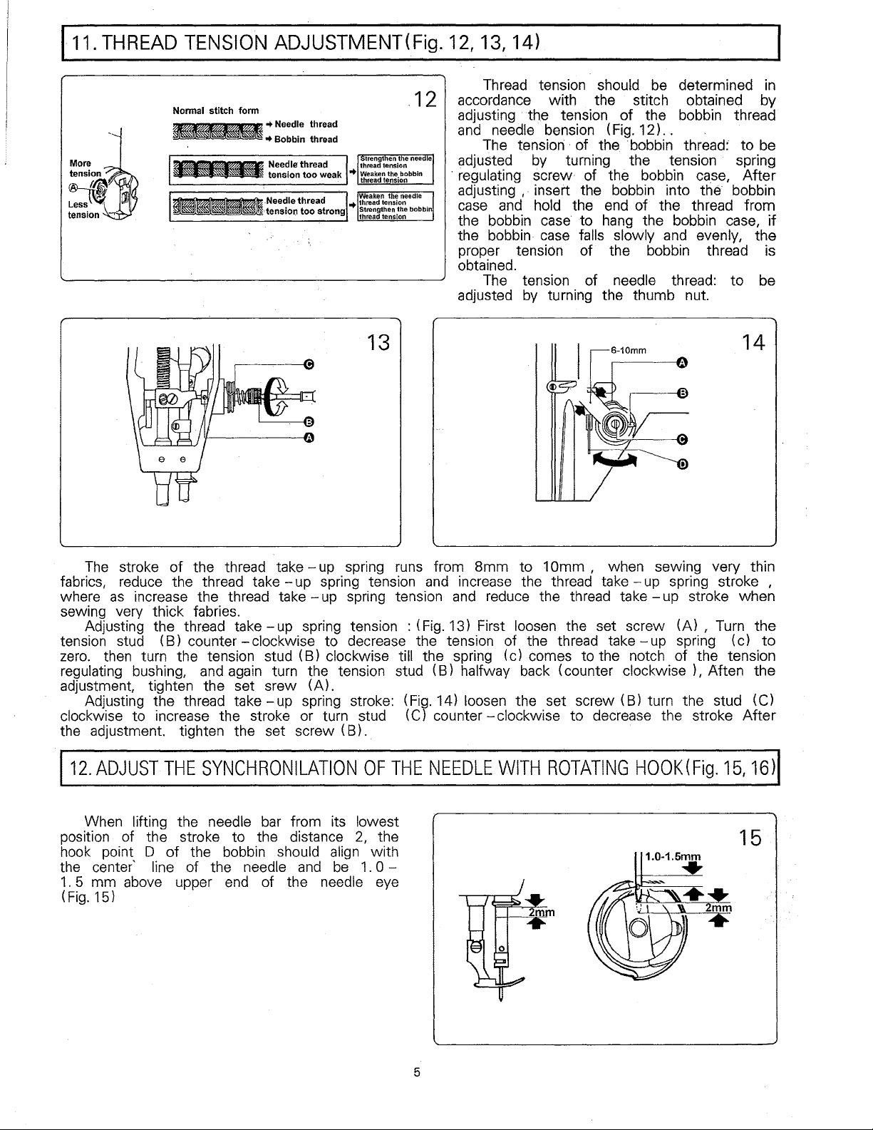
Pressure of the presser foot
accordance with thickness of materials to
sewn.
First loosen the lock nut (A) , for
materials, turn the pressure regulating thumb
as
screw
pressure
pressure regulating thumb screw
Fig.
11
tighten the
The
recommended to
feeding
shown
, while for light materials , turn the
(b) to decrease the pressure , the
pressure of the · presser foot
is
THE
in
Fig.
lock nut (A).
be
ensured.
PRESSURE
is
11
(a) to increase the
as
less
as
long
OF
PRESSER
adjusted
heavy
shown
as
normal
be
in
in
is
FOOT(
Fig.
11
I
CD
l
1 1
4
!11.
THREAD
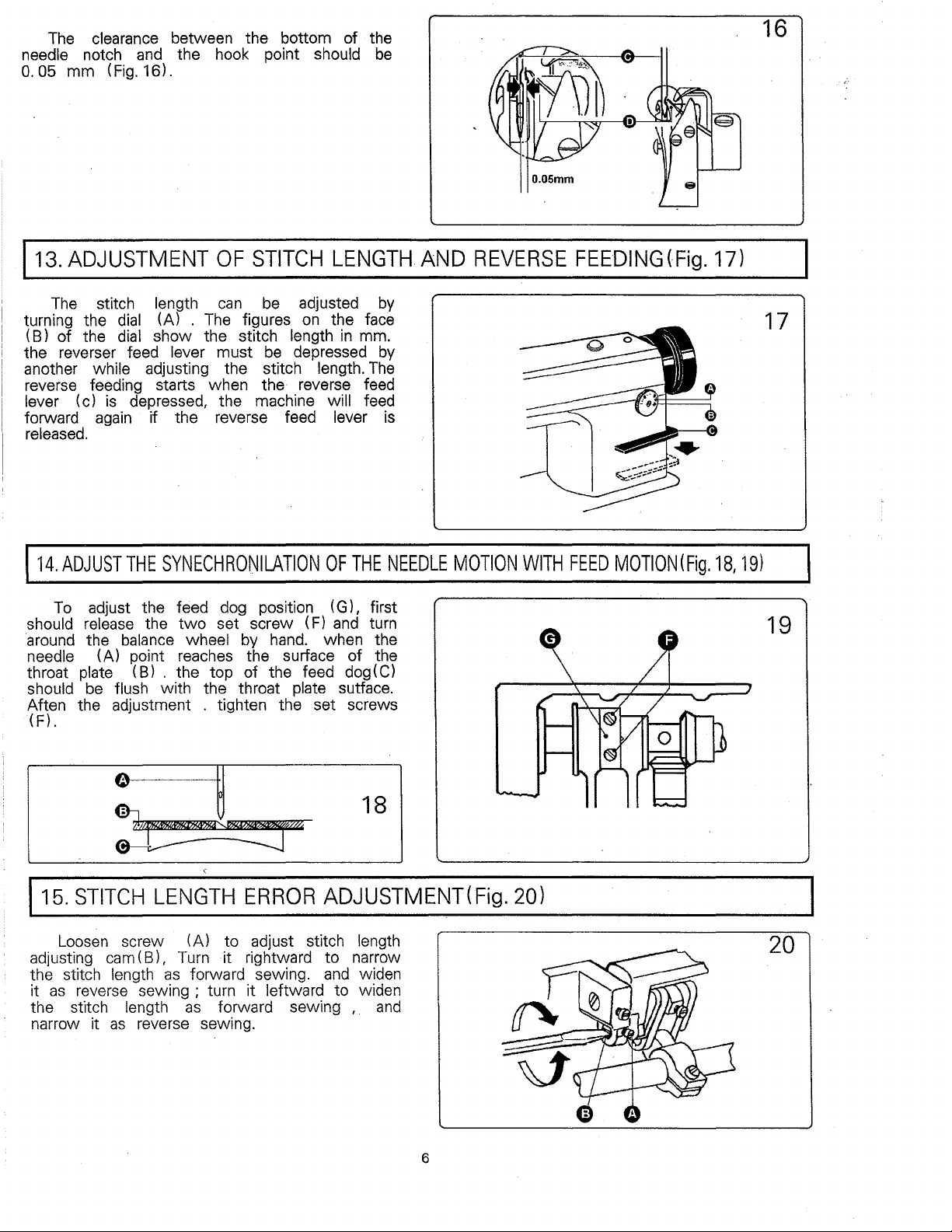
Nonnal stitch fonn
~1\1~~
=~
TENSION
==~==~=~=
~--~Needle
~
ADJUSTMENT(
•
Need~e
• Bobbm thread
·tension too strong
thread
thread
Fig.
12, 13, 14)
Thread tension should be determined in
. 1 2 accordance with the stitch obtained by
adjusting
and
adjusted by turning the tension spring
· regulating screw of the bobbin
adjusting ,
case and
the bobbin case to hang the bobbin case,
the bobbin· case falls slowly and evenly, the
proper
obtained.
adjusted by turning the thumb nut.
· the tension
needle· bension (Fig.
The tension· ·
· insert the bobbin into the bobbin
tension
The tension of
of
the ·bobbin thread:
hold the end
of
of
the bobbin thread
12)..
to
be
ca,se,
of
the thread from
the bobbin thread is
needle thread:
After
to
be
if
13
The stroke
fabrics, reduce the thread take
where
sewing very thick fabries.
tension stud
zero. then turn the tension stud (B) clockwise till the spring (c) comes to the notch of the tension
regulating bushing, and again turn the tension stud (B)
adjustment, tighten the set srew
clockwise
the adjustment. tighten the set screw
as
Adjusting the thread take
Adjusting the thread take
of
the thread take
increase the thread take
(B)
counter
to increase the stroke or turn stud (C) counter
-clockwise
-up
spring runs from
-up
spring tension and increase the thread take
-up
spring tension and reduce the thread take
-up
spring tension : (Fig. 13) First loosen the set screw (A) , Turn the
to decrease the tension of the thread take
halfway back (counter clockwise ) , Aften
(A).
-up
spring stroke: (Fig. 14) loosen the set screw (B) turn the stud (C)
(B).
8mm
to 1
-clockwise
Omm
, when sewing very thin
-up
spring stroke ,
-up
-up
spring (c)
to decrease the stroke
stroke when
14
to
the
After
112.
ADJUST
When lifting the needle bar from its lowest
position of the stroke
hook point
the center'
1.
5 mm above upper end of the needle eye
(Fig. 15)
THE
SYNCHRONILATION
to
the distance
0
of
the bobbin should align with
line of the needle
and
be
OF
2,
1.
THE
the
0 -
NEEDLE
5
WITH
ROTATING
HOOK(Fig.
15,
15
16)1
The
clearance between the bottom of the
needle notch
0.
05
mm (Fig. 16).
and
the hook point should
16
be
113.ADJUSTMENT
The
stitch length
turning the
(B) of the
the reverser feed
another while adjusting the stitch length.
reverse feeding starts when the reverse feed
lever (c)
forward
released.
114.
ADJUST
To
should release the
·around
needle (A) point reaches the surface of the
throat
should
Aften the adjustment . tighten the set screws
(F).
dial
(A) .
dial
show the stitch length
is
depressed, the machine will feed
again
adjust the feed dog position (G), first
the
plate (B) . the top of the feed
be
if the reverse feed lever
THE
SYNECHRONILATION
balance
flush with the throat plate sutface.
OF
can
The
figures
lever must
two
set screw (F)
wheel
by
STITCH
be
adjusted
on
be
depressed
hand.
LENGTH
by
the face
in
mm.
The
OF
THE
and
turn
when the
dog
(C)
AND
by
is
NEEDLE
REVERSE
MOTION
WITH
FEEDING(Fig.
FEED
MOTION(Fig.
17)
18,
17
191
19
18
115.
STITCH
Loosen
adjusting
the stitch
as
reverse sewing ; turn it leftward to widen
it
the stitch
narrow it
cam
LENGTH
screw (A) to adjust stitch length
(B),
Turn
length
as
as
forward sewing.
length
reverse sewing.
as
ERROR
it rightward to narrow
forward sewing , .
ADJUSTMENT(
and
widen
and
Fig.
201
6
20
116.
117.
FEED
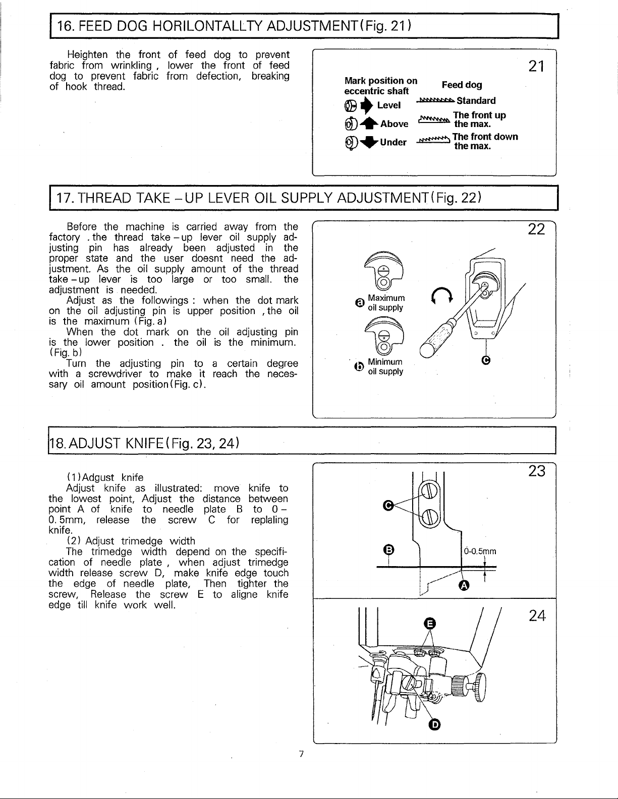
Heighten the front of feed dog to prevent
fabric from wrinkling , lower the front of feed
dog
to prevent fabric from defection,
of
hook
THREAD
DOG
thread.
HORILONTALLTY
TAKE
-UP
LEVER
ADJUSTMENT(Fig. 21)
breaking
OIL
SUPPLY
Mark
position
eccentric shaft
@.Level
@+Above
®+under
on
N:Mr:N:N:.
~
~The
ADJUSTMENT(
Feed
The
Fig.
dog
Standard
front
the
max.
front down
the
max.
22)
21
up
Before the machine
factory . the thread
justing
proper state
justment.
take
adjustment
on
is
is
(Fig.
with a screwdriver to make it
sary
118.
the lowest point, Adjust the distance between
point A of knife to needle plate B to
0.
knife.
cation of needle
width
the edge of needle plate,
screw,
edge
pin
has
already
and
the user doesnt
As
the
oil
-up
lever
Adjust
the
oil
the maximum (Fig.a)
When
the lower position . the
b)
Turn
the adjusting
oil
amount position(
ADJUST
(
1)
Adgust knife
Adjust knife
5mm, release the screw C for replaling
(2) Adjust trimedge width
The
trimedge width depend
release
Release
till knife work well.
is
is
. needed.
as
the followings : when the dot mark
adjusting
the dot mark
KNIFE
as
p·late
screw
the screw E to
is
carried away from the
take-
too large
up
lever
oil
supply
been
supply amount of the thread
pin
is
on
pin
Fig.
(Fig.
illustrated: move knife to
, when adjust trimedge
D,
make knife
adjusted
need
or
too
upper position , the
the
oil
oil
is
the minimum.
to a certain degree
reach
c).
23,
24)
on
the specifi-
edge
Then
aligne
in
the
small.
adjusting
the neces-
0-
touch
tighter the
knife
adthe
ad-
the
oil
pin
~
€)
Maximum
• oil supply
~
·
6)
Minimum
• oil supply
22
23
24
7
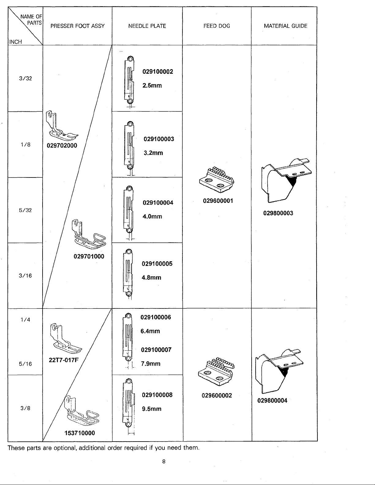
3/32
PRESSER
FOOT
ASSY
NEEDLE
029100002
2.5mm
PLATE
FEED
DOG
MATERIAL
GUIDE
1/4
5/16
3/8
'
'
~
~
029100006
6.4mm
029100007
7.9mm
029100008
9.5mm
029600002
153710000
These parts
are
optional, additional order required if you need them.
8
029800004
9
 Loading...