

Consew 261B User Manual
(-
..
-··-··-··-··-··-
i
i
i
i
.....
-
..
-
..
._··-··-
OPERATING
..
-··-
_
..
_
..
_
&
..
_
..
_
..
I
~
t !
, , I
"'
I
:
i
i
i
i
i
i
i
I
I
i
,.
ADJUSTMENT
MANUAL
INCLUDING
PARTS
CON
MODEL
SEW
LIST
261s
'
i
i
i
i
i
i
i
I
CONSOLIDATED
SEWING
MACHINE
CO
'
t
........
·-··-··-··---··---··-··-··-··-··-··-··---··-·······....-.··········-··-··-··"""""·

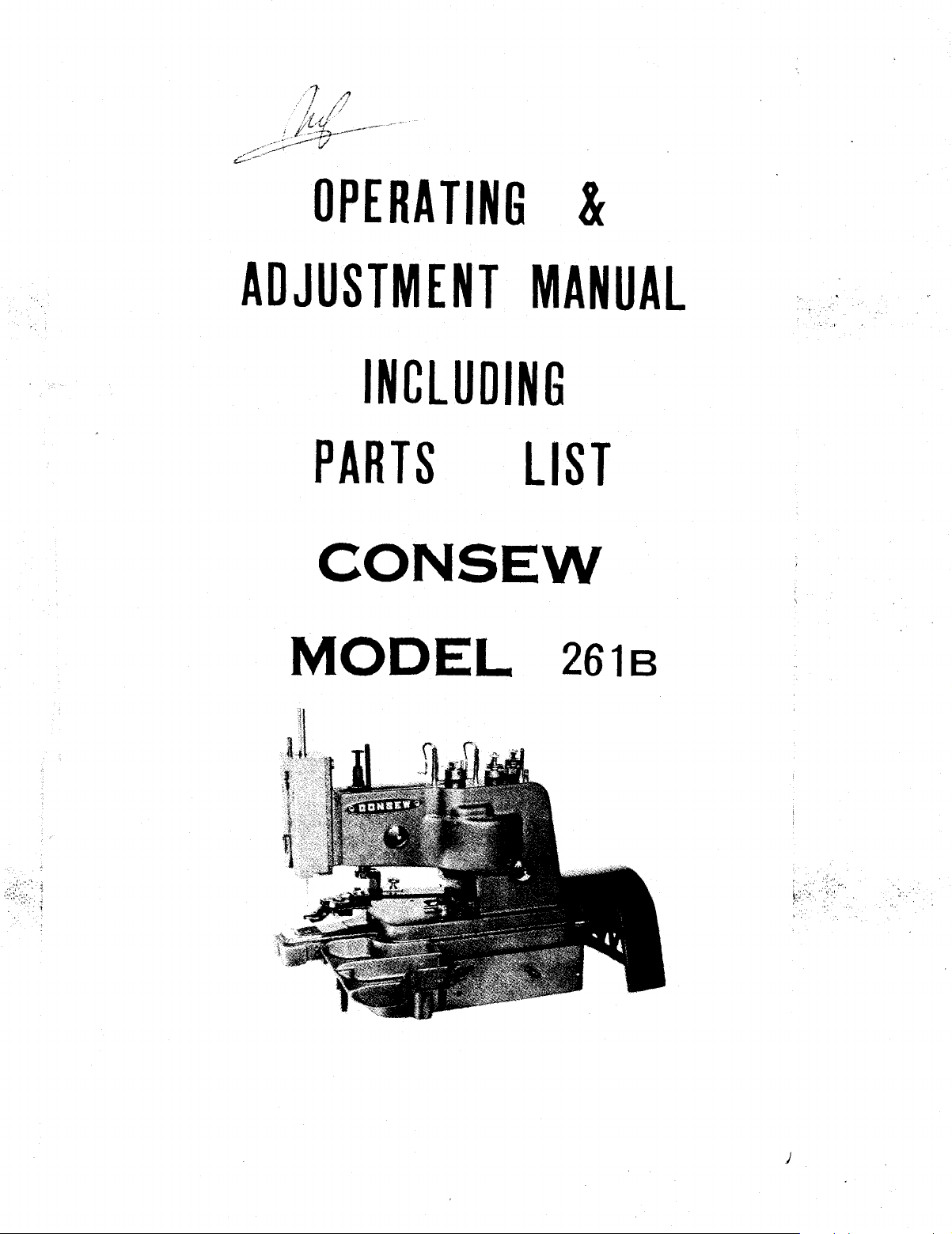
OPERATING
&
ADJUSTMENT
MANUAL
INCLUDING
PARTS
CON
MODEL
SEW
LIST
261s
- . .
.
~.
.
)
DESCRIPTION
OF
MACHINE
Consew
buttons
stitch. Adjustments are possible
1/64
for
sewing
The
metal
sizes
must not
up
When
Model
with a total
to
7 132
2 and
Consew
eyelet
to
Mode\261
shank buttons,
45
seWing
exceed
261 B
apart.
4-hole
ligne.
nat
5
18".
is
a single
of
16 stitches
Standard
nat buttons from
B can be
leather
buttons, the toto\ thickness
OPERATING
thread
to
equipment
equipped
and
chain stitch machine
including a cross-over
accommodate
provides
20
for
imitation
buttons
to
45
sewing
leather
SPEED
for
and a
with
holes
for
a
button
ligne.
self shank buttons,
shank buttons in
of
material
and
attaching
knotting
from
clamp
button
The sew1ng speed
minute.
figured
Carefully
small parts and accessories
To
obtain
to
have o
unpack machine
of
the
2-l
the machine, must not
correct
/2"
diameter.
SEniNG
are
from
removed
pulley
UP
MACHINE
packing
exceed l 000
ratios,
from
the
drive
case and make sure
packing
materiQI.
-1
stitches
pulley
is
that
to
per
be
all
Wipe
with
a good grade
Machine
machine clean
of
is
set
up
uf
protective grease
stainless sewing machine
on
table
so
that its face plate faces the operator.
and
lubricate all oil holes
oil.
(see
below)
Prepare table by boring
apart, at a distance
distances are measured to the center
Place machine
additional holes in table to accommodate the
Important
rection, when standing at its rear and looking at the drive pulley.
Note
base
: Machine
two
belt holes
of
14-1
/2"
from the front edge
in proper relation
must
of
of
rotate
at least 5
the holes.
to
these
two
only
in
/8"
diameter 1 2-1
of
the
table.
belt holes and bore
treadle chains.
counter-clockwise
OILING
/2"
All
di-
Do not operate the machine, even
been properly oiled at every spot requiring lubrication.
Oiling
tinuous operation to
The
which
is
being lubricated.
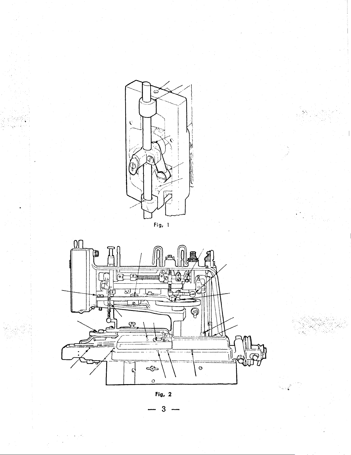
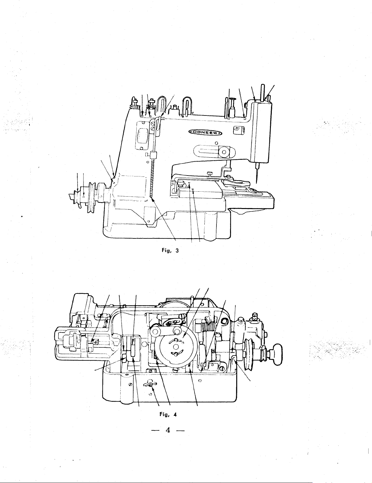
fig. 1 1 the
in
Fig. 2 shows the machine
the
two
must
be
arrows on
must
receive one
two
knurled nuts,
done at least twice
assure
Figs.
screws holding the face plate
free-running and
1 through 4 point to those parts
or
two
drops
Note
that in order to reach the oiling points indicated
with
the arm side cover removed
while
fig. 4 shows the bottom
if
only
daily,
durability
of
for
when the machine
of
oi
I every time the machine
will
2-
testing,
the operating parts.
have to be removed.
of
unless
of
the machine
by
the machine.
it
is
in con-
loosening
has
fig,
1
Fig, 2
-3-
Fig, 3
Fig,
4
-4-
Note:
During the
breaking-in
period, a new
machine should be
oiled
more
tighten
' >
frequently.
When
wing
oiling
is
completed,
nut at its
right
turn machine
side.
down
onto
its base and
firmly
I
NEEDLES
Consew
Sizes
The size
must
pass
Remember uneven, knotted
performance
For
or
burred needles
Model
16, 18,
of
freely
of
bes~
results
261
Bt
uses
needles
20
and
22
the needle
through the needle eye.
the machine.
use
to
only
assure
is
determined
or
rough thread impairs the
genuine
satisfactory
CON
INSERTING A
Style
NEW
17
5 X 7
by
the
SEW needles. Replace bent,
operation
(Cat.
s1ze
of
of
the machine.
No.
the
thread
satisfactory
NEEDLE
4531 l
which
sew1ng
dull
Insert the needle up
the
long
groove
tighten
the needle set
TO
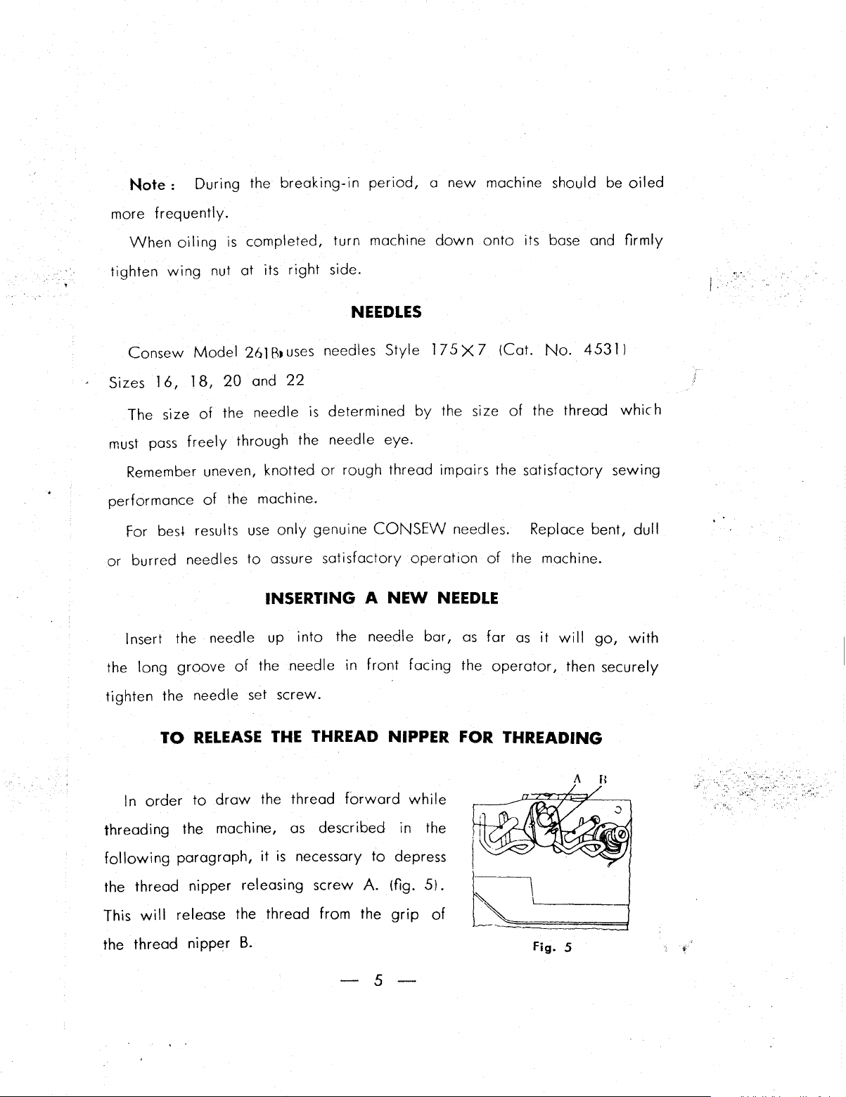
In
order
threading
following
the thread nipper releasing
This
will
the
thread
to
the machine,
paragraph,
release the thread from the
nipper
of
RELEASE
draw
B.
the
needle
screw.
THE
the thread
as
it
is
into
the needle
in
front
bar,
facing
as
the
far
as
operator,
it
will
THREAD NIPPER FOR THREADING
forward
described
necessary
screw
A.
to
(fig.
grip
while
in the
depress
5).
of
II''·--"A:"C7/~~I
t_~~
Fig. 5
-5-
go,
with
then securely
A B
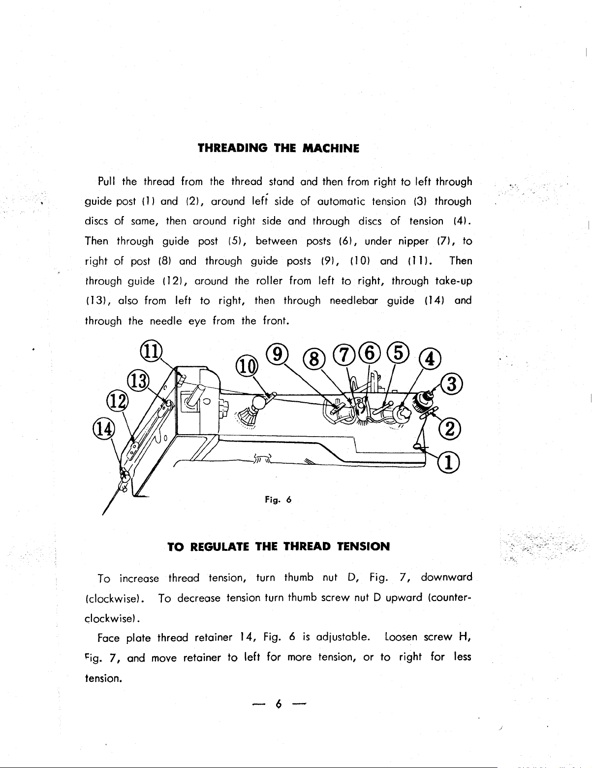
THREADING
Pull
the thread from the thread stand and then from right
121,
guide post ( 1 l and
of
of
same,
post
discs
Then through guide post
right
then around right side and through discs
(8)
and through guide posts
around
left
(5),
between posts
THE
side
of
MACHINE
to
left
through
automatic tension (3) through
of
tension (4).
(6),
under nipper (7),
(9),
(1
OJ
and
(11
l.
to
Then
through guide
(13),
through the needle eye from the front.
also from
(12),
around the roller from
left
TO
REGULATE
to
right, then through need Iebar guide (14) and
fig.
THE
THREAD
left
to
right, through take-up
6
TENSION
To increase thread tension, turn thumb nut D, Fig.
(clockwise). To decrease tension turn thumb screw nut D upward (counter-
clockwise).
Face
l=ig.
7,
tension.
plate thread retainer
and move retainer
to
14,
left
Fig. 6
for
more tension,
is
adjustable. loosen screw
-6-
or
to
7,
downward
right
for
H,
less
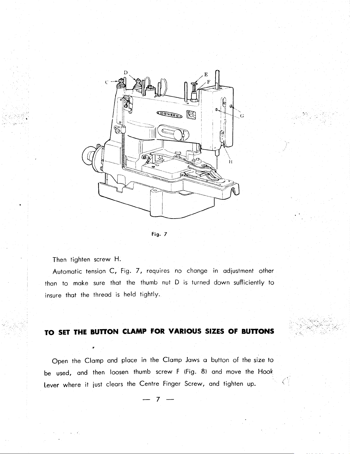
Then tighten screw H.
Automatic tension
than
to
make sure that the thumb nut D
C,
Fig.
Fig. 7
7,
requires no change in adjustment other
is
turned
down
sufficiently
to
insure that the thread
TO
SET
THE
BUnON
Open
be used, and then loosen thumb screw F (Fig. 8) and move the Hook
Lever where
the
Clamp
it
just clears the Centre Finger Screw, and tighten up.
is
held
tightly.
CLAMP FOR VARIOUS SIZES OF
and place
in
the
Clamp
Jaws a button
-7-
BUnONS
of
the size
to
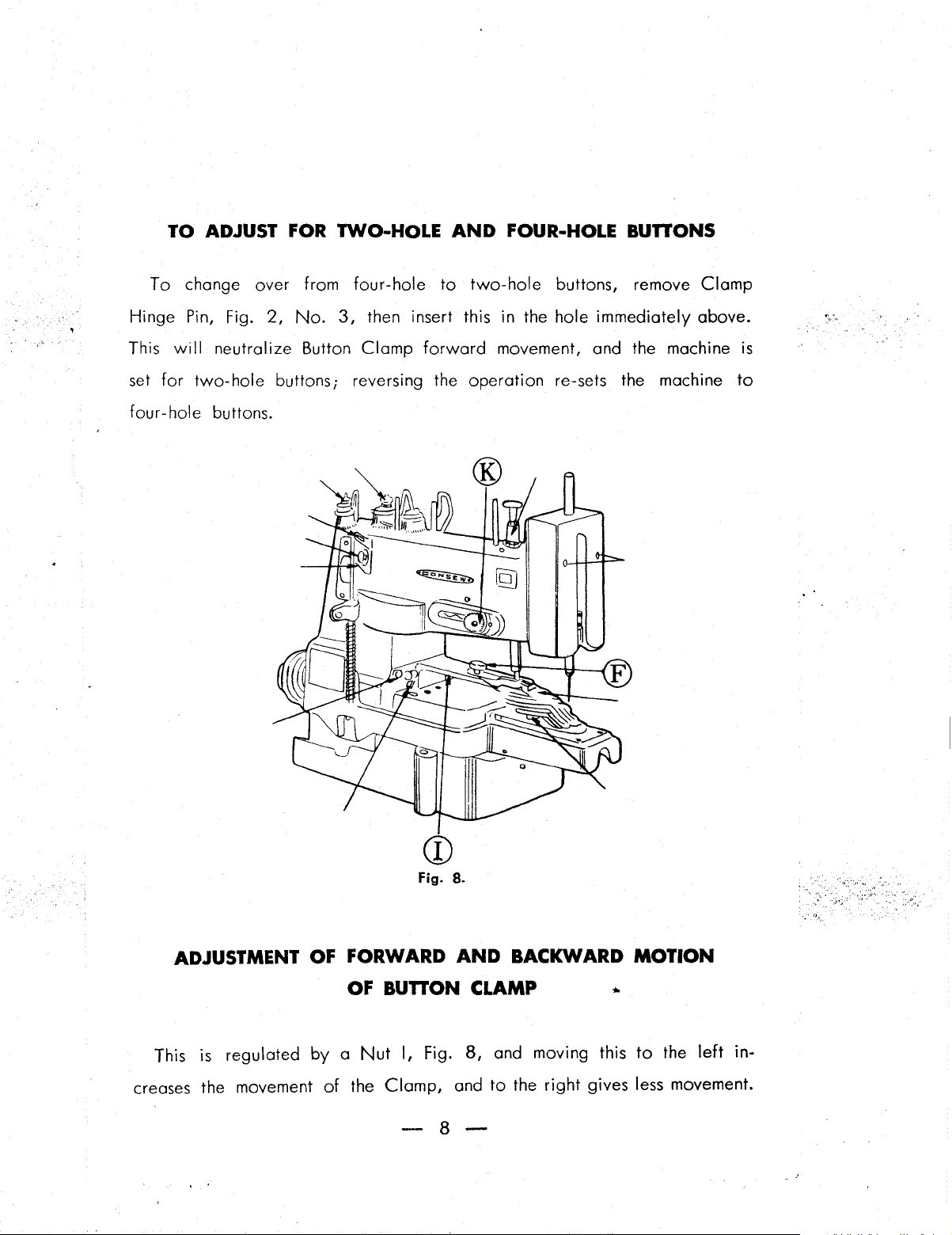
TO
ADJUST
To
change over from four-hole
FOR
TWO-HOLE
AND
to
two-hole
FOUR-HOLE
buttons, remove
BUnONS
Clamp
Hinge Pin, Fig.
will
This
set
for
four-hole buttons.
neutralize Button
two-hole
2,
No.
3,
then insert this in the hole immediately above.
Clamp
buttons; reversing the operation re-sets the machine
forward
movement, and the machine is
to
Fig.
a.
ADJUSTMENT
This
1s
regulated
creases the movement
OF
FORWARD
OF
by a Nut
of
the
BUnON
I,
Fig.
Clamp,
AND
BACKWARD
CLAMP •
8,
and moving this
and
to
the
right
-8-
MOTION
to
the
left
in-
gives less movement.
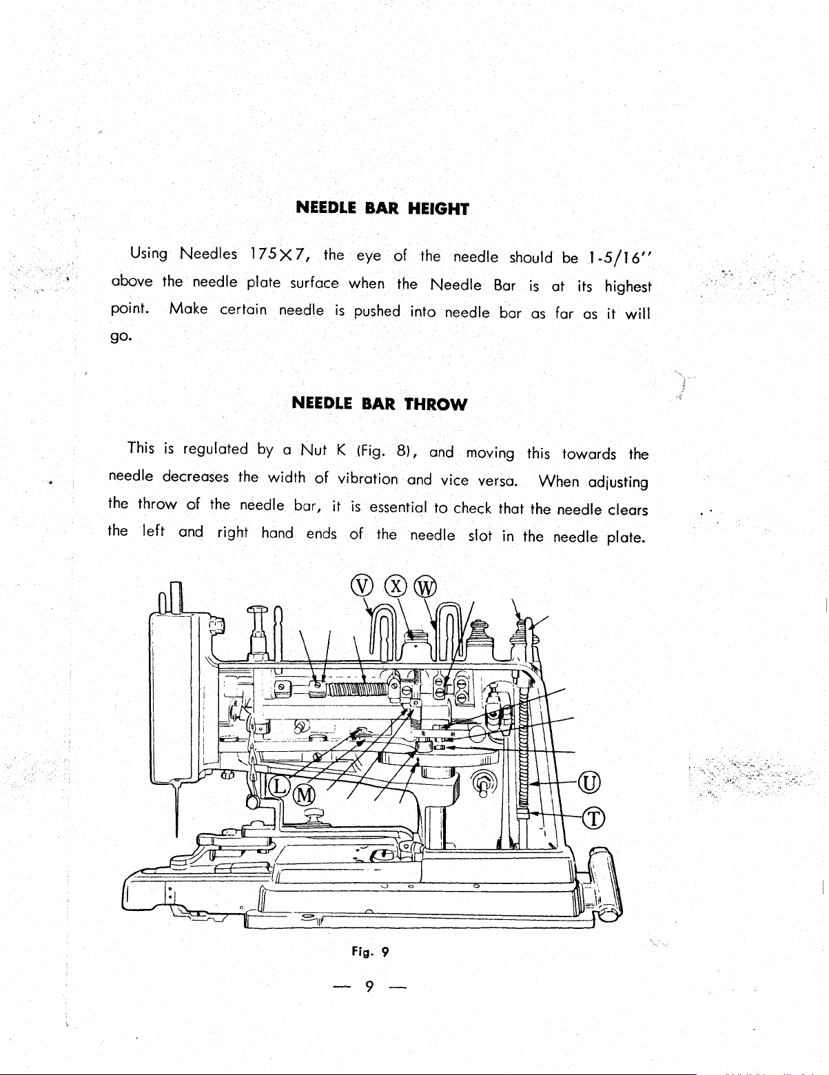
NEEDLE
BAR HEIGHT
Using Needles
above the needle plate surface when the
point.
go.
This
needle decreases the
the
the
Make
is
throw
left
regulated by a
of
the needle bar,
and right hand
l75X7,
certain needle
NEEDLE
Nut
width
of
ends
the eye
is
of
pushed into needle bar
BAR THROW
K !Fig.
vibration and vice versa.
it
is
of
8),
essential
the needle slot in the needle plate.
the needle should be
Needle
and moving this towards the
to
Bar
is
as
When
check that the needle clears
1-5/16"
at its highest
far
as
it
adjusting
will
Fig. 9
-9-
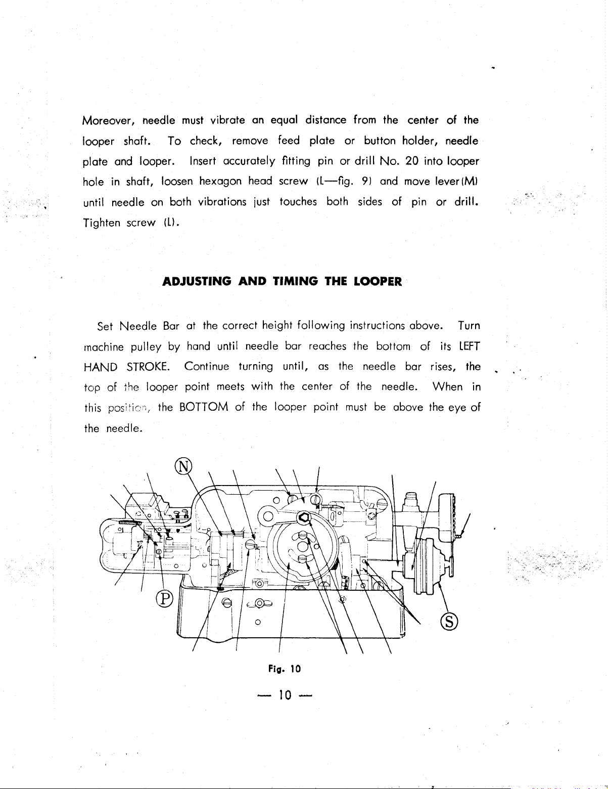
Moreover,
looper shaft.
plate and looper.
needle
To
must
vibrate on equal distance from the center
check, remove feed plate
Insert accurately fitting pin
or
button holder, needle
or
drill
No.
20
into looper
of
the
. I
hole in shaft, loosen hexagon head screw
until needle on both vibrations just touches both sides
Tighten screw
Set
Needle
machine
HAND
top
this
the needle.
pulley
STROKE.
of
the looper point meets
posi
Ill.
ADJUSTING
Bar
at the correct height
by
hand until needle bar reaches the bottom
Continue turning until,
the
BOTTOM
AND
of
TIMING
with
the center
the looper point
(L-fig.
THE
following
as
the needle bar rises, the
9) and move
LOOPER
instructions above. Turn
of
the needle.
must
be
lever(Ml
of
pin
or
drill.
of
its
When
above the eye
LEFT
in
of
Fig.
10
-10-
If the looper on its
LEFT
HAND
STROKE
is not timed exactly
as
de-
·.:.,
scribed,
loosen set screws
turn looper shaft until looper
ceeding paragraph. Check accuracy
..
-·
securely. Correct timing
will
Since this part serves
ler,
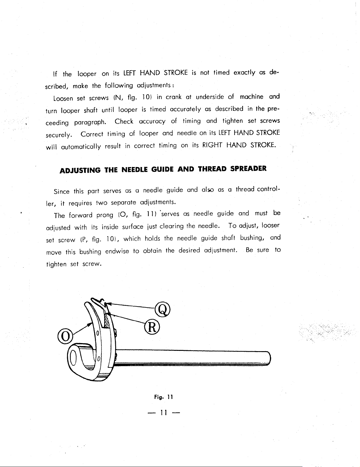
The forward prong
adjusted
set
move this bushing endwise to obtain the desired adjustment.
make
the
following
!N,
fig. 1
of
adjustments:
Ol
in crank
is
timed accurately
looper and needle on its
automatically result in correct timing
ADJUSTING
it
requires
with
screw
!P,
THE
NEEDLE
as
two
separate adjustments.
(0,
flg. 11)
GUIDE
a needle guide and also
"serves
its inside surface just clearing the needle.
flg. 1 Ol, which holds the needle guide shaft bushing,
at
underside
as
of
timing and tighten set screws
on
its RIGHT
AND
THREAD·
as
needle guide and
of
machine and
described in the pre-
LEFT
HAND
HAND
STROKE.
SPREADER
as
a thread control-
To
adjust, looser
Be
STROKE
must
be
and
sure
to
:
...
~"'.
••
.;
'~"'
,·,
..
: 0
set
tighten
'',
.'
screw.
Fig.
11
-
11-
...
The rear ·prong serves
of
that the point
the needle on its
as
thread spreader. It should be adjusted so
downward
stroke clears the inside
.,,,
corner
the
quired, loosen clamp screw (P, fig.
quired position. Securely tighten clamp screw upon completion
. justment.
Depending upon the type
ing used, the needle bar
its upward stroke after the automatic tension
To
turn same
collar
(R,
fig. 11}
needle bar
adjust the timing, loosen both
for
the main shaft
makes
to
required position.
of
its left hand stroke. If adjustment should be re-
TIMING
the.
thread finger
THE
of
buttons and materials and the thread be-
sho1..1ld
of
the machine. Therefore, its side
by
10,
and turn needle guide
AUTOMATIC
move 3
set
Note
/8"
screws on cam
that
approximately 1
TENSION
to
about 5
has
released the thread.
cam
/8"
(S,
also serves
/32"
to
fig. 1
to
of
complete
OJ
as
thread
must
when
re-
ad-
and
con-
tact the machine bed. Tighten set screws
ADJUSTING
The amount
adjusting
the desired
between the upper end
the automatic tension
discs.
nuts
Securely tighten
of
(T, fig.
play
opening
is
obtained. There should be about 1
9}.
THE
AUTOMATIC
of
the automatic tension
Loosen
of
the rod and the tension release washer when
is
closed
nuts
upon completion
them and turn rod (U, fig. 9} until
without
-12-
securely.
TENSION
is
controlled
/64''
any thread between the tension
of
adjustment.
by
the
clearance
of
ADJUSTMENT OF THREAD
The
thread pull-offs !V and
the
thread post about 1
W,
fig.
9l
should move back
/2"
when the button clamp
PULL..OFFS
to
the
is
in its highest
left
· ' position. To adjust loosen
shaft inside the machine
arm
THREAD NIPPER
The
thread nipper !X, fig.
is
in
machine
downward for tighter thread nipping
sure
to
tighten
stopped position. It
set
screw
on
set
screws which lock
and
move forward
9)
should hold
is
or
collar.
these
or
back
the
thread tightly while the
adjusted by moving the collar
upward for
parts
as
less
to
set
forth above.
gripping.
the top
Be
-13-
LIST
OF
FOR
PARTS
'·
..
'
CON
SEW
MODEL
261s
 Loading...