

Page 1
..................
.r.SmcefBDB
DNSEWe
CONSOLIDATED
L
INDUSTRIAL
OPERATING
CONSEW
INDUSTRIAL
SEWING
and
MACHINE
SEWING & CUTTING
INSTRUCTIONS
PARTS
for
MODELS
SEWING
LIST
18
CORP.
and
MACHINES
EQUIPMENT
118
IDA
TED
SEWING
MACHINE
Page 2
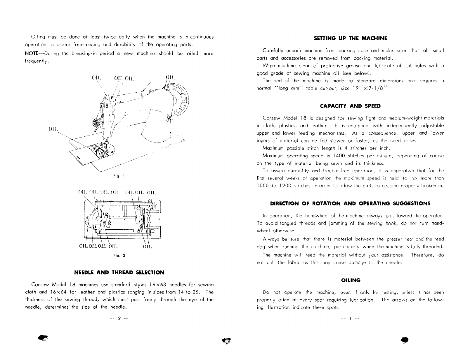
Oiling
must be done
operation
NOTE--During
frequently.
to
Oil
at
least
twice
daily
when
assure
free-running
the
breaking-in
and
durability
period a new
of
machine should be
OIL
O~I/
. /
\ I /
· hr
e
.
OIL
~----~~
;-~
'·.~'··I-·
·(
J
r·
- I I
~Jl
.-~..-'
;.
------------,.
( ;
~~~--"'
·,
~
OIL
Oll
OIL OIL
~'
'
/~~~..-'---
~~
Fig.
1
OIL OIL
r~r~~~-w-~_
I
~~(r)~VJ~
!(
\C
__:]!it(~
'11.~.
I
OIL
OIL OIL
---~-
)\(~
OIL
Fig. 2
the machine
the
operating
~~OI~L
1/
:?: ,
,r---.......
is
in continuous
ports.
oiled
__.,
· ,
I
\WJ
I
_J1})o
'
(?
more
~.:;::1
OIL
OIL
Carefully
ports and accessories
Wipe
good
The bed
normal
Consew
in
cloth,
upper and
layers
Maximum
Maximum
on the
To
first several weeks
1
000
unpack machine
machine
grade
"long
plastics, and
of
materi<;~l
type
assure
to 1 200
clean
of
sewing
of
the machine
arm"
Model
lower
feeding
possible stitch length
operating
of
material
durability
stitches in
ore
table
18
is
can be fed
of
operation
DIRECTION OF ROTATION
In
operation,
To
avoid
wheel
otherwise.
Always
dog
when running the machine,
The machine
not
pull the
the handwheel
tangled
threads and jamming
be sure that there
will
feed
iabric
as
SEniNG
removed from packing
of
machine
cut-out,
CAPACITY
designed
leather.
mechanisms. As a consequence, upper and
speed
being
and
order
the
this rnay cause damage
UP
THE
MACHINE
fror:1
packing case and make sure that
material.
protective
is
is
troublefrce
is
material
grease and
oil
!see
below!.
made
to
standard dimensions and requires a
size
19"X7-1/8"
AND
for
sewing
It
is
equipped
slower
or
faster,
is
4 stitches per inch.
1400
stitches per minute, depending
sewn and its thickness.
operation,
the maxin1urn speeJ
to
allow
the parts
AND
of
the machine
of
material
particularly
between
without
lubricate
SPEED
light
and
with
as
it
to
OPERATING SUGGESTIONS
always
the sewing hook,
the presser feet and the feed
when the machine
your
to
the needle.
all
oil
medium-weight
independently
the need arises.
is
imperative
is
held to no more than
oecome
assistance.
turns
oropcr!y
toward
do
is
all
holes
materials
adjustable
of
that
broken in.
the
operator.
not turn
fully
threaded.
Therefore,
small
with
lower
course
for
the
hand-
a
do
Consew
cloth
and 1 6 X
thickness
needle,
NEEDLE
Model
of
determines the size
I 8 machines use
64
for
the
sewing
leather
thread,
AND
THREAD SELECTION
standard
and plastics
which
of
.the
needle.
-
styles I 6 X
ranging
must pass
2-
in sizes
freely
63
needles
from
through
1 4
the
to
for
25.
eye
sewing
of
•
The
the
~
Do
properly
ing
illustration
not
operate
oiled
the machine, even
at
every
spot
indicate
these spots.
OILING
requiring
if
only
for
testing, unless
lubricatio'1. The
1
--
arrows
•
it
on the
has been
follow-
Page 3
..
.,...,
Remember-uneven,
performance
Only
<=!
length
thread counterclockwise.
unravels,
The bobbin can be wound
of
your
left twist thread
of
thread between thumbs and index fingers
it
has
machine.
a right
knotted
is
If
twist.
to
it
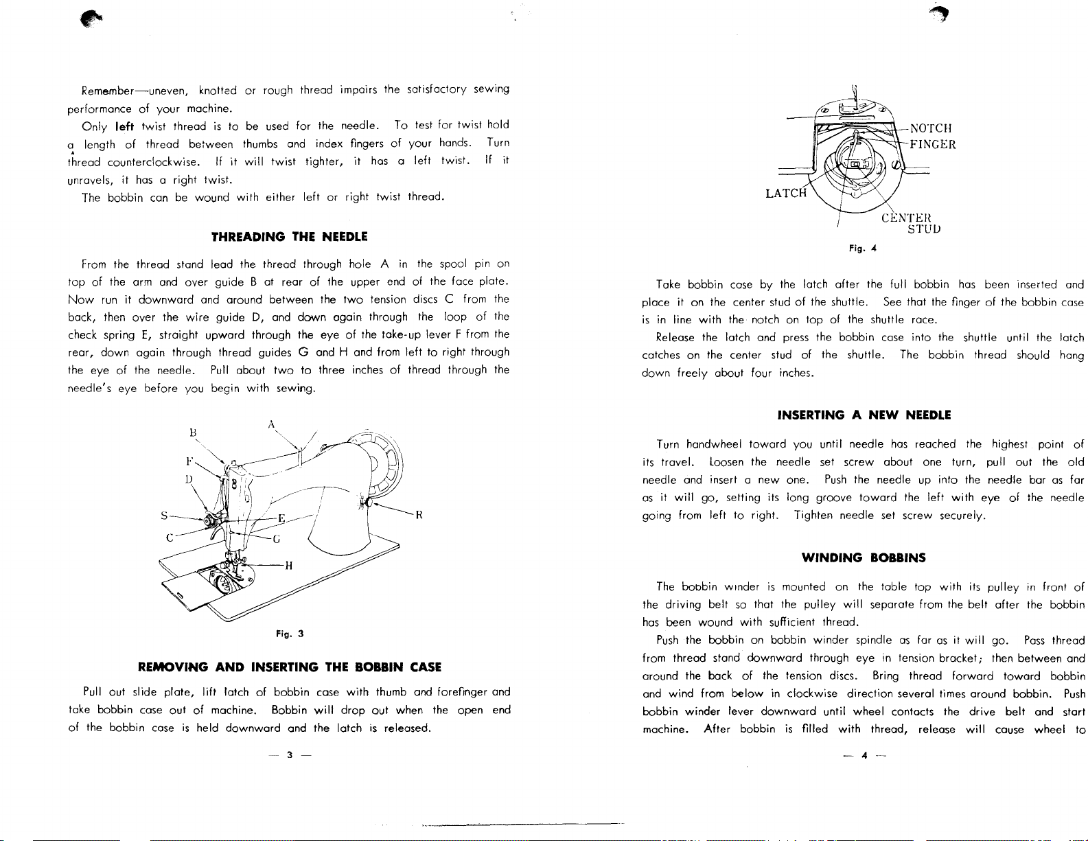
THREADING
From
the thread stand lead the thread through hole A in the spool pin on
top
of
the arm and
Now
run
it
downward
back, then
check spring
rear,
the eye
needle's eye before you begin
over
E,
down
again through thread guides G and H and from
of
the needle. Pull about
over
guide B at rear
and around between the
the
wire
guide
straight
upward
B
or
rough thread impairs the satisfactory sewing
be used
will
with
D,
through the eye
with
twist
either
and
two
sewing.
for
the needle. To test
tighter,
left
THE
of
down
to
it
has a left
or
right twist thread.
NEEDLE
the upper end
two
tension discs C from the
again through the
of
the take-up lever F from the
three inches
for
of
your
hands. Turn
twist.
of
the face plate.
loop
left
to
right through
of
thread through the
twist
of
hold
If
the
it
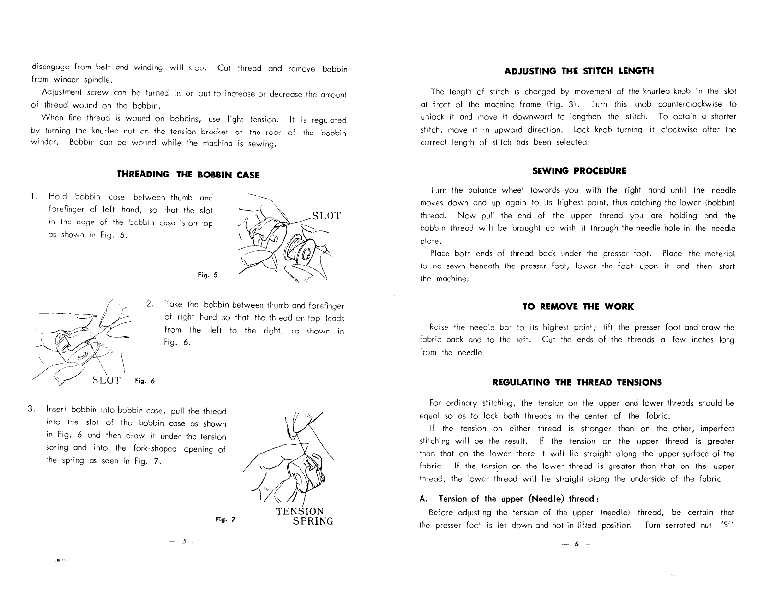
Fig. 4
Take bobbin case
place
it
on the center stud
is
in line
with
Release the
catches on the center stud
down
freely
about four inches.
Turn handwheel
its travel. Loosen the needle set screw about one turn, pull
needle and insert a
as
it
will
go,
going from
left
by
the latch
the notch on
latch and press the bobbin case
INSERTING A NEW
toward
setting its long groove
to
right. Tighten needle set screw securely.
you until needle
new
one.
after
the full bobbin
of
the shuttle.
top
of
of
the shuttle. The bobbin thread should hang
See
that the finger
the shuttle race.
into
NEEDLE
has
reached the highest point
Push
the needle up
toward
the
has
been ·Inserted and
of
the bobbin case
the shuttle until the latch
out
the
into
left
with
the needle bar
eye
of
as
the needle
of
old
for
Fig. 3
REMOVING
Pull out slide
take bobbin case
of
the bobbin case
plate,
out
AND
lift
latch
of
machine. Bobbin
is
held
downward
INSERTING
of
bobbin
and the latch
3 -
THE
case
will
BOBBIN
with
drop
CASE
thumb and forefinger and
out
when the open end
is
released.
The
boobin w1nder
the
driving
has
been
Push
from thread stand
around the bock
and
bobbin
machine.
belt
wound
the bobbin on bobbin
wind
from
winder
lever
After
WINDING
is
mounted on the table top
so
that the
with
downward
of
below
downward
bobbin
pulley
sufficient thread.
winder
through eye in tension
the tension discs. Bring thread
in clockwise
until wheel contacts the
is
filled
BOBBINS
will
separate from the
spindle
direction
with
thread, release
-4-
with
its
pulley
in
front
belt
after
the bobbin
as
far
as
it
will
go.
Pass
bracket;
several times around bobbin.
then between and
forward
drive
will
cause wheel
toward
belt
and start
of
thread
bobbin
Push
to
Page 4
disengage from
from
winder
Adjustment screw can be turned in
of
thread
When
by
turning the knurled nut on the tension bracket
winder.
belt
and
spindle.
wound
on the
fine thread
Bobbin can be
is
winding
bobbin.
wound
wound
on
while
will
stop.
or
bobbins,
the machine
out
Cut
thread and remove bobbin
to
use
increase
light
at
is
or
decrease the amount
tension.
the rear
sewing.
It
of
is
regulated
the
bobbin
The length
at
front
unlock
stitch, move it in
correct length
of
of
the machine frame
it
and move
of
ADJUSTING
stitch
is
it
downward
upward
stitch
has
THE
changed
direction.
by
(fig.
to lengthen the stitch. To
been selected.
STITCH
movement
31. Turn this knob
Lock knob turning
LENGTH
of
the knurled knob in the slot
counterclockwise
obtain
it
clockwise
to
a shorter
after
the
THREADING
1.
Hold
bobbin case
forefinger
in
as
--
~~'--~
-~
I,
.
-"---(
of
left
hand,
the edge
shown in Fig.
~--~-
t
~~}!~"-'
of
the bobbin case
5.
'--~
" I
\
·~-/
\
\
\ )cL:;,;:; \ \
)/
/-/
./
\r
3.
Insert bobbin into bobbin case,
into
in Fig. 6 and then
spring and
the spring
s .
the slot
as
'LOT
of
the
draw
into
the fork-shaped opening
seen in Fig.
between
so
that the slot
2.
Take the bobbin
of
from the
Fig.
Fig. 6
bobbin
it
under the tension
7.
THE
BOBBIN
thumb and
is
on
top
Fig. 5
right hand
6.
pull
the thread
case
as
left
shown
of
CASE
---·----......,,
between
so
that the thread on
to
thumb and forefinger
the
right,
as
shown in
top
leads
Turn the balance
moves
down
thread.
bobbin thread
plate.
to
the machine.
fabric
from the needle
Now
Place both ends
be sewn beneath the presser
Raise
the needle
back and
wheel
and up again
pull the end
will
be
brought
of
thread back under the presser
bar
to
the
REGULATING
For
ordinary
so
equal
If
the tension on
stitching
than that on the
fabric
thread, the
stitching, the tension on the upper and
as
to
lock both threads in the center
either
will
be the result.
lower
If the tension on the
lower
thread
SEWING
towards
to
of
TO REMOVE
to
its highest
left.
Cut
thread is stronger than on the
If
there
it
lower
will
lie
PROCEDURE
you
with
the
its highest
the upper thread
up
foot,
THE
the tension on the upper thread is
will
straight
point,
thus catching the
with
it
through the needle hole in the needle
lower
the
foot
THE
WORK
point;
the ends
lift
the presser
of
the threads a
THREAD TENSIONS
of
lie
straight
thread
is
along
greater
along
the underside
right
hand
until
the needle
lower
you
are
holding and the
foot.
Place the material
upon
it
and then start
foot
and
few
inches long
lower
threads should be
the
fabric.
other,
the upper surface
than that on the upper
of
the
(bobbin)
draw
the
imperfect
greater
of
the
fabric
Fig.
7
-- 'i
..
A.
Tension
Before adjusting the tension
the presser
of the upper
foot
is
let
down
(Needle)
and not in
thread:
of
the upper (needle) thread, be certain that
lifted
position Turn serrated nut
- 6 -
'S"
Page 5
•
ACCESSORIES
BOBBIN
KNEE
PRESSER
PARTS
WINDER
LIFTER
FOOT AND
FOR
WIPER
Tne
word
No.
means a
INDEX
••• , ...
, . .
.....
...... ......
• · · · · · · · · · · · · · · · · · · · · · · · · · · · · · · · · · · · · · · · · · 2
................................................
UPPER
FEED
SEAM
C stem ped
.. ·
complete
......
at
DOG
· ·
the side
set
......
······ ......
..
.. .. .. · .. · 7
.... · ......
of
of
the porto,
· · · .. 7
ports
PAGE
8
J/7
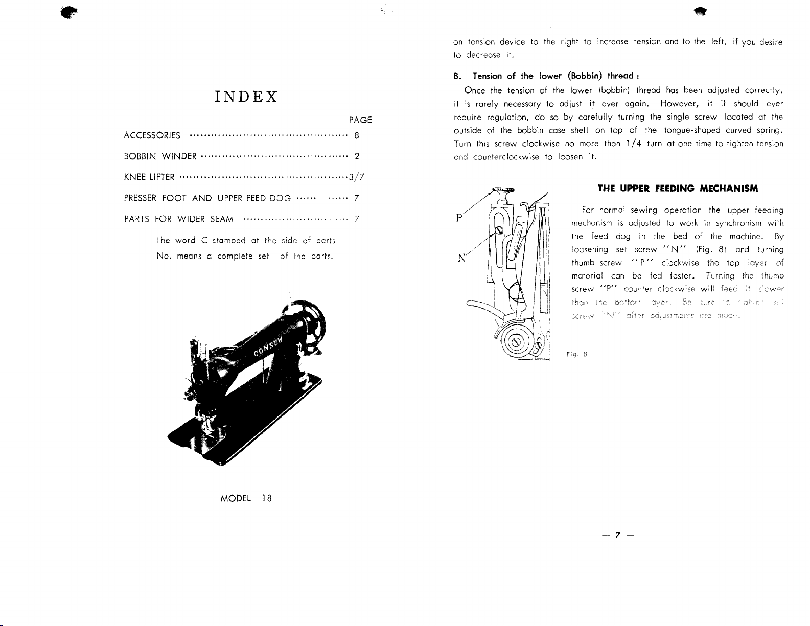
on tension
to
decrease
B.
Once
it
is
require
outside
Turn this screw
and counterclockwise
device
Tension
the tension
rarely
regulation,
of
the bobbin case shell on
//
to
it.
of
the
necessary
do
clockwise
l\/
'\~i
~"0··;
N~.~·
\ I .
~~~~,;
1\\~_.V
I
J8:f·
~-.
the right
lower (Bobbin) thread:
of
the
to
so
to
\·
•'
to
increase tension and
lower
!bobbin) thread
adjust
it
ever
again.
by
carefully
no more than 1
loosen
For normal sewing
mechanism
the feed
loosening set screw
thumb screw
material con be fed foster. Turning the thumb
screw
fig.
turning the single screw
top
of
/4
it.
THE
UPPER
is
odju3ted to
dog
"
"P"
cou'1ter
•
to
the
left,
if
you desire
has
been adjusted
However,
the tongue-shaped curved spring .
turn
at
FEEDING
operation
in the bed
"N"
P"
clockwise
clockwise
it if
one time
MECHANISM
the upper feeding
work
in synchronism
of
the machine.
(fig.
the
will
correctly,
should ever
located
to
tighten tension
8) and turning
top
feed
at
Ioyer
the
with
By
of
MODEL
18
-7-
Page 6

PARTS
NO.
6004
6005
6006
6007
6008
6009
6010
6010
6011
6012
6013
6014
6015
6016
6017
6018
6019
6020
6021
6022
6023
6024
6025
6026
6027
6027
6027
6028
6029
6029
6030
PAGE
101
103
104
104
105
103
106
106
106
106
106
106
106
106
106
110
105
103
101
105
103
103
103
101
103
103
103
101
101
109
106
NAME
Oscillating rock shaft crank
!I
Lower
II
Lower
shaft crank
shaft
II
11
slide block
11
Shuttle driver
Shuttle race body
shuttle race complete
Shuttle race back
II
11
II
II
II
II
II
II
II
11
body
spring
II
II
cap sprjng
II
screw
screw
Bobbin case
Bobbin
Feed
rock
shaft rocker
Feed
driven rock shaft crank
Feed
ba.se
Feed
lifting rock shaft
II
II
II
II
II
II
Feed base center screw
Feed
rock shaft center screw
Feed
lifting rock shaft center screw
Center screw with
bar
crank
II
II
with
nut(8013)
Feed dog
11
set screw
Upper feed rod
pin
set screw
Needle plate
shaft screw pipe
roller
set screw
nut
complete
PARTS
NO.
6031
6033
6034
6035
6050
c
6051 c
6052
c
6053
6054
6055
6056
6057
6058
6059
6060
6061
6062
6063
6064
6065
6066
6067
6068
6069
6070
6071
6073
6074
6075
6076
6077
PAGE
106
106
106
106
109
109
109
109
109
109
109
109
109
109
109
109
109
109
109
109
109
109
109
109
109
110
110
110
110
111
111
NAME
Needle plate set screw
Slide plate
Oscillating hook slide friction spring
Slide plate spring screw
Bobbin winder complete(6051 C
&
Bobbin winder
Bobbin winder spool stand complete
II
II
II
If
II
II
II
II
II
II
II
!I
II
II
Bobbin winder tension
II II
II II
II
base
pulley
spindle
frame
stop latch
frame hinge screw
II
" spring
stop latch hinge screw
pulley set screw
spool stand
11
pin
tension screw stud
disc
II
spring
regulating thumb nut
II
II
thread guide
II
screw
11
Wrench
Scale
11
Machine rest
set screw
pin(
wood)
Machine hinge plate
Machine hinge connection
6052
nut
C)
-1-
•
-2-
.,
•
Page 7

•
~
•
PARTS
NO.
6321
6322
6323
6324
6325
6326
6327
6328
6329
6330
6331
6332
6332
6333
6334
6335
6336
6337
6338
6339
6340
6341
6342
6343
6344
6345
6346
6347
6348
6349
PAGE
106
106
106
102
102
102
106
106
103
103
103
104
104
l 04
102
102
102
102
102
102
102
102
102
102
102
102
102
102
102
103
NAME
Thread take
II
II
II II
II
II
Needle
II II
up
cam
II
II
II
II
bar
crank pipe
11
II
II
II
crank
connecting stud
screw
roller stud
II
pin
Needle bar
Needle clamp
Needle bar thread guide
Thread take
Thread take
II
up
up
II
lever complete
lever
11
set screw
Upright bracket plate
Upper feed dog set plate
II
II
II
II
II
II
II
II
II
11
base
II
II
pin
II
bracket
II
II
screw
Presser bar guide bracket
II
II
II
1.'
II
II
set screw
roller
II
II
Presser bar attaching bracket
11
Presser bar lifter
11
11
set screw
& knee lifter connecting rod conne-
ctor
II II
II
II
Upper feed dog set plate connecting plate
11
11
double binding screw
Middle presser foot
-4-
PARTS
NO.
6078
6079
6080
6081
6082
6083
6084
6085
6086
6087
6088
6088
6088
6088
6090
6303
6304
6305
6306
6307
6308
6309
6310
6311
6313
6314
11
pin
6315
6316
6317
6318
6320
PAGE
111
111
111
111
111
111
111
111
1,11
111
111
111
111
111
112
103
104
101
102
102
108
102
102
102
102
101
l
09
NAME
Machine hinge plate set screw
Knee
lifter complete
Rock
shaft for 6079
II
11
hanger
II
11
knee arm
II
II
II
II
11
n
11
11
11 11
Drip
II II
II
II
II
11
11
11
" lifting bracket set screw with hook
pan
pJate
11
arm hub
lifting bracket
II
hook
II
stop dog
knee arm set screw
11
plate screw
stop
dog
set screw
Upper feeding rock shaft front metal
II
II
II
Upper feeding rock shaft
"
II
"
1/
II
II
11
rear metal
bme
Feed cam
Upper feed forked connection
11
11
regulator box
II
II
II
slide stud
Balance wheel
Upper feed regulator thumb screw
11
11
II
II II II
II
II
11
screw
II II
(long)
rece1ver
II
Upper feed rod
II II
set pin
set screw
set screw
-3-
Page 8

PARTS
NO.
6350
6351
6352
6353
6353
6354
6355
6356
6356
6357
6358
6359
636Q
6361
6363
6365
6366
6367
6368
6369
6270
6371
6372
7020
7023
7025
7026
7027
7028
7029
7030
PAGE
103
103
109
107
107
108
108
109
109
108
103
109
109
109
109
105
106
104
104
104
104
104
107
107
107
107
] 07
107
107
NAME
Upper feed dog
Presser bar lifting lever
II
II
set screw
Face plate
Face plate complete
Knee
lifter lifting lever
II
Lifting
lever connecting bar
Lifting
lever connecting bar complete
Arm
side cover
II
hook
Presser bar thumb screw nut
Lifting
lever connecting bar joint
II
II
II
II
11
11
Upper shaft screw
Upper shaft
Needle bar crank set screw
Knee
lifter bell crnak body
II
it
"
II
II II
II
II
11
11
" spring
set screw
Upper feed rod base
II
II
set screw
Feed regulator body
Tension spring receiver
Tension thread guide
11
11
11
11
(big)
(middle)
(small)
Thread take up spring
Tension releasing
/I
II
pin
nut
joint set screw
pin
PARTS
NO.
8007
8007
8008
8009
8009
8010
8012
8013
8013
8013
8013
8014
8014
8014
8020
8020
8023
8031
8031
8031
8035
8036
8037
8039
8040
8042
8053
8054
8056
8057
PAGE
1
04
1
04
104
104
108
101
101
1
01
103
103
103
101
101
101
103
103
106
107
107
103
104
103
103
103
103
104
101
104
104
104
NAME
Feed cam set screw
Balance wheel screw
Rear bush
II
Knee
lifter lifting lever hook screw
screw
Crank connecHng rod
Oscillating rock shaft crank shaft
II
If
If
nut
Feed rock shaft center screw nut
Oscillating rock shaft crank shaft screw pipe nut
Feed lifting rock shaft center screw
Forked rod screw
Connecting rod screw
Feed regulator connecting rod screw
Lower shaft crank
pin
Shuttle driver pin
Thread take
Upper feeding rock shaft
up
cam
pin
pin
Tension spring receiver set screw
Tension thread guide set screw
Needle bar thread guide set screw
Thread take
up
lever roller with nut
Presser regulating thumb screw
Presser bar spring
Presser bar
Upper feed dog screw
Lower
shaft crank set screw
Forked rod
Feed regulator connecting rod
Feed regulator set screw
11
thumb srew
·---
!::'
--.
.....
--6-
-
Page 9

..
·•
..
PARTS
NO.
8060
8060
8076
8077
8078
8079
8086
8091
8093
8102
8104
8115
8116
8119
6349
6350
6349
6350
6349
6350
6349
6350
6349
63130
PAGE
107
107
107
107
107
107
109
106
109
109
104
110
110
110
113
113
113
113
113
113
113
113
113
113
NAME
Tension thread guide set screw(middle)
Face plate set screw
Tension screw
Tension disc wheel
Tension spring
Tension stud nut
Knee
lifter lifting lever hinge screw
Shuttle race set screw
Arm
side cover set screw
Spool
pin
Feed regulator screw washer
Screw driver
11
Oil can
PRESSER
FOOT
Middle presser foot
Upper feed dog (
Middle presser foot
Upper feed dog
Middle presser foot
Upper feed dog
Middle presser foot
Upper feeb dog
Middle prsser foot
Upper feed dog
stud.
(big)
(small)
AND
FEED
DOG (Different size)
(standard)
11
(bottom
( II
( II
( II
( II
( II
( II
( II
)
1
/8"
II
3/16"
II
1/4"
II
5/16"
II
grooved)
II )
II )
II )
II )
II )
II )
II )
PARTS
NO.
6312
6319
6362
6364
6071
6073
6074
8115
8116
8119
PAGE
PARTS
Upper feed regulator box (instead of
Upper feed rod (instead of
Upper feed regulator thumb screw(instead of
Feed regulator body (instead of
CONTENTS OF
110
110
110
110
110
110
Wrench
Scale
Screw driver
Oil can
Oil
Needle 3 pes.
Bobbin 3 pes.
FOR
11
WIDER
ACCESSORIES
set screw
11
NAME
SEAM
(big)
(small)
6318)
BOX
7020)
631
0)
6314)
-7-
-8-
Page 10

6335
6326
....
6325
0
6324
If
~
6334
6318
6309
8010
8053
6348
6345
6347
11
6346
H
6343
6344
<':
...
6337
~
6336
6311
~
-102-
6314
T
6315
"""""""
6340
6341
ceQ
6316
5
6317
6310
I
f
~
8014
0~
8014
o:=
6029
6021
4
0
6004
g
6028
6026
....
6026
41111
-101-
8012
0
8013
~
•
~
Page 11

..
.(lilt:,
-
630?
t))Q5
0
8013
1§1
8036
n
6358
r()
6023
6020
~
8031
'i"
6009
j319
6329
~
6024
~
·-
6025
...e
8020
~
II
6330
~
6331
\)
6027
8
39
. -
II
cl040
i1
6350
~
8037
I!
7020
~
8056
p:
8104
0
8057
~
8054
'"L~
8042
6006
•
8008
.
6308
=
8009
8007
-
8035
9.
6367
6369
6007
a
=
~
6332
6332
63:;t-
•
6368
~
6027
-103-
I
L
La_
a
-104-
Page 12

0..
·-·
0
'()
e
N
N
I
0
'{)
.:(
::
::: : : : :
L
:;;;
:::
::
:
::::~
m:;;
::y
:::!
:J
·==r~
L!".)
0
....
e
M
<')
'"
'()
N
C'J
'0
"-
0
'()
u
0
0
'-()
M
N
0
00
~
<f)
0
'()
'1"
0
'()
('<
I
N
M
'{)
'()
0
'()
0
0
'()
'
'{)
'{)
M
'{)
"-
N
M
'()
Ctm
a
0..
0
00
I
'
7
M
M
0
-.o
0
("')
0
'()
M
0
'{)
<f)
M
0
'{)
••
••
M
0
~
-.o
<.0
0
......
M
0
'{)
1.0
00
N
M
'()
A
0
'()
0J
0
-.o
f.
Page 13

f'
Ll")
Ll")
M
'()
r
M
M
'<)
0')
~/)
C')
··O
co
('J
0
"
Ll")
N
~
!"'-
o-
0
0
co
J
•
'<)
N
0
~'
<>
('.,
0
CD
~::p
r
~
•.
\.."'·~
0
"7
Ll")
M
'<)
0
(")
0
"
(")
0
00
0
'()
0
w
()<. 0
C"-j
:::.-::)
,,
,..-'
--
•
...
ex,
0
-
t-
0
......
('..
''
...
{=)
co
'.(;
f·,
0
co
~
C'J
.:.._·:.
co
!'.
0
CD
•
Page 14

co
c
)
0
"'
co
a-.
0
Page 15

c:.~
m
0
c:=
'D
ro
ro
0
'D
'0
ro
ro
0
'D
I
""
C)
""
'D
t
'-C
"-
0
"-'
Page 16

6350
6349
l
••••••••••••••••••••••••••
PARTS FOR 118
REVERSE
FEED
~,,I
•
6350
•
6350--;£
6350
-~
-}f(,
6349--
6349-M,
~
r
6616;:
8105 8014
6623
1
6617
••••••••••••••••••••••••••
:~
 Loading...