

Page 1
CONSOLIDATED SEWING MACHINE CORP.
I . .
INDUSTRIAL
SEWING
&
CUTTING
Model
106R
EQUIPMENT
INSTRUCTION
&
PARTS
BOOK
MANUAL
Page 2
Table
of
Contents
1. Introduction
2. Main specifications
................................................................................................................
........................................................................................................
3. Installation and preparation
Installation
1) Location
2) Installing
3) Mounting machine head
4) Mounting
5) Installing
6) Connecting
7) Installing
8) Installing
Preparation
1) Cleaning
2) Examination
3) Lubrication
4) Trial run
4. Operation
5. Adjusting
6. Adjustments
7. Cleaning
8.
Trouble
..............................................................................................................................
1) Selection
2) Coordinating between needle,
3) Installing
4) Winding
5)
Threading
6) Setting the bobbin
7) Installing
8) Setting stitch length
Presser
9)
10) Adjusting the pressure on
thread
1) Adjusting
2) Adjusting
3) Adjusting
1. Timing between needle
1) Adjusting position
2) Adjusting rotating hook timing with needle
3) Removing
2. Adjusting
1) Adjusting
2) Adjusting
3. Adjusting
.....................................................................................................................
1. Cleaning
2. Cleaning
shooting
..•.•...........................................................................•.......................................
of
the
machine
drip
pan
.........................................................................................................
rock
shaft
bracket
the
motor
........................................................................................................
the
clutch lever to the pedal.
the
bobbin
the
thread
.....................................................................................................................
the
machine
.................................................................................................................
..................................................................................................................
.....................................................................................................................
of
the
the
needle
the
bobbin
the
the
bobbin case
bar
height position
tension
the
thread
the
thread
the
tension
.............................................................................................................................
and
the
feed dog
the
height
the
position
the
tension release mechanism
the
feed dog
the
rotating hook
..............•.•.....................•..................................•.....•............•...............
winder
un-winder
.................................................................•....................................
thread
........................................................................................................
thread
needle
installing
thread
...........................................................................................................
and
............................................................................................................
take-up
guide
of
of
the
........................................................................................................
.............................•..............................................•..........................
.......................................................................................................
............................................................................................
...................•...................................•.........•.............•...................
..................................................................................................
knee lifter
.............................................................................................
.........................................................................................
.....................................................................................................
thread
...............................................................................................
and
..................................................................................................
reverse sewing
................................................................................................
the
presser
spring
................................................................................................
needle
and
the
......................................................................................................
thread
rotating hook
needle
bar
rotating hook
................................................................................................
...............................................................................
..............................................................................
and
sewing material.
drawing
....................................................................................
the
bobbin
................................................................................
foot
..........................................................................
....................................................................................
and
bobbin
.............................................................................
..........................................................................
............................................................................
..............................................................................
thread
.......................................................
thread
.....................................................
.........................................................
.
.
.
.
.
.
.
.
.
.
.
.
.
.
.
.
.
.
.
.
.
.
.
.
.
.
.
.
.
.
.
.
.
.
.
.
.
.
.
.
Page 3
1.
Arm
and
Bed
..•.•••...•..•.....••••...•...•.......•......•.•..••...•.......•....•....••.•.............•...•.•..••.....•..•.......
2.
Needle
Arm
3.
4. Rotating
5. Stitch length Regulating
6. Feed dog lift mechanism
Presser
7.
Lubrication
8.
9. Knee lifter
10. Bobbin
11.
12. Accessories
shaft
Thread
arm
and
thread
and
vertical
hook
and
bar
and
drawing
..........•.............................................................................................................
....•....••.......•......•...•.......•...•.........••...•.......•.•....•..•..•.........••.........•..•....•....•.......•..
winder
un-winder
............................................................................•......................................
.......................................................................................................................
shaft
shaft
..•.•..•.....•.....•.........••.....••......•....................•................•..•..•...••...•.....•...••..
Parts
take-up
......................................................................................................
parts
.......................................................................................................
.............................................................................................
........................................................................•..........................
...............................................................................................
bar
.................................................................................................
catalogue
.
.
.
.
.
.
Page 4

Operating Instructions
Page 5
1.
Introduction
The
Consew
usage.
a
large
smooth
beautiful,
tarps,
pillows,
106R
It
is
engineered
rotating
and
even
even,
hook
flat
shoes
2. Specifications
1)
Max.
Sewing
2) Max. stitch length:
3)
Presser
4)
Max. thickness
5) Needle:
6)Hook:
7)
Motor:
foot lift:
speed:
sewing
feed
stitches
of
material to be sewn:
machine
with a needle
with a double
when
and
sewing a single
and
worker
is a
thread
is
widely
safety
single
bearing,
capacity.
layer
used
items.
needle,
thread
of
in
the
lockstitch
link
take-up,
It
has
all
fabric
or a lap
manufacture
designed
spiral
the
advantages
seam.
of
suitcases,
for
medium
bevel
gear
of a low
The
Consew
leather
2000
9mm
6.5
w/knee lifter
up to 8 layers
a thickness
DPx5,
Large
double
Yz
Motor
to
heavy
transmission
torque,
106R
goods,
spm
mm-13mm
of
of
8 mm each
#18~22
rotating hook with
HP,
thread
1PH,
capacity
llOV
duty
and
low noise,
produces,
handbags,
leather, with
Clutch
3. Installation
1)
Placement
To
ensure smooth vibration free operation, the machine should be placed on
Placing
vibration.
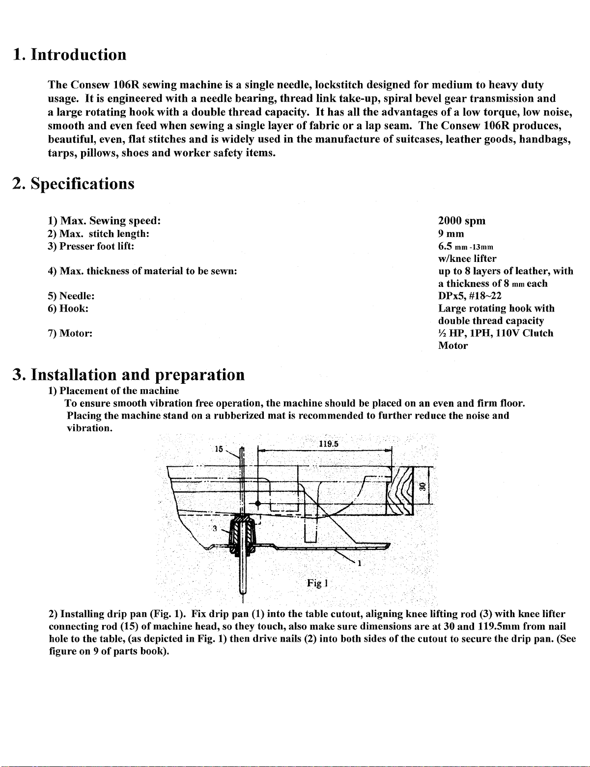
2)
Installing
connecting rod (15)
hole to the table, (as depicted in Fig. 1) then drive nails (2) into both sides
figure on 9
of
the
drip
of
parts
and
the
machine
preparation
machine
pan
(Fig. 1). Fix
of
machine head, so they touch, also make sure dimensions
book).
stand
on a rubberized
drip
pan
mat
(1) into
is recommended to
the
table cutout, aligning knee lifting
further
reduce the noise
are
of
the cutout to secure the
an
even
at
30
and
firm floor.
and
rod
(3) with knee lifter
and
119.5mm from nail
drip
pan. (See
Page 6
3)
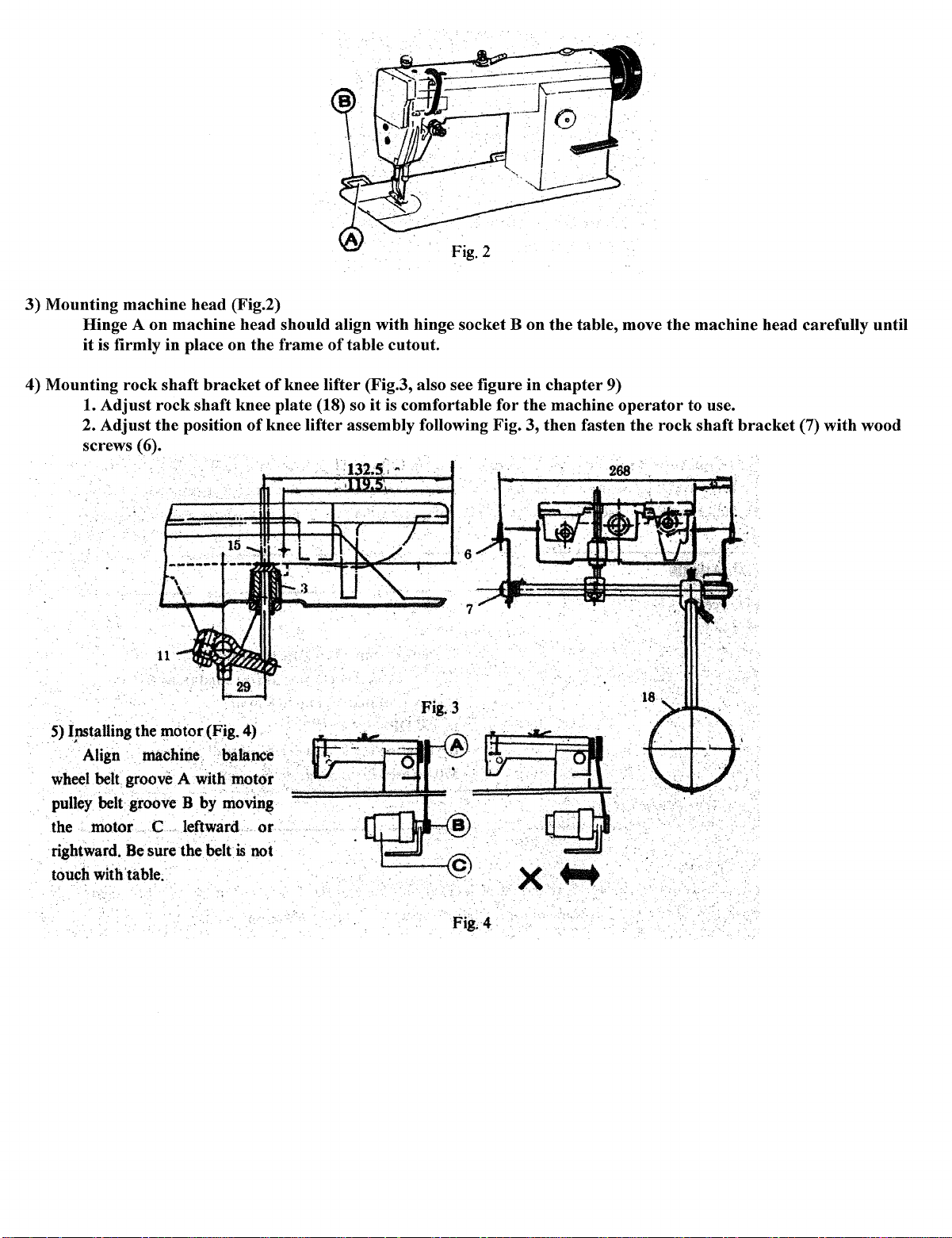
Mounting machine head (Fig.2)
Hinge A on machine head should align with hinge socket B on
it
is firmly in place
4) Mounting
1.
Adjust
Adjust
2.
screws (6).
rock
shaft
rock
the
on
bracket
shaft knee plate (18) so
position
Fig.2
the
table, move
the
frame
of
of
knee lifter assembly following Fig. 3, then fasten
of
table cutout.
knee lifter (Fig.3, also see figure in
it
is comfortable for
7
the
chapter
machine
9)
operator
the
the
machine head carefully until
to use.
rock
shaft
bracket
(7) with wood
5)
Installing the motor(Fig. 4)
' . .
Align machine.
wheel
belt
groove A with
pulley belt groove B by
the motor .
rightward. Be sure the
with'tilble.
touch
C.
leftward
belt
~lance
motor
mo~n$
...
or
is
not
~
Ernl.
·.·.·.···.···.··.··~.~
.
.··
...
·
..
......
x. · ....
FigA
Page 7
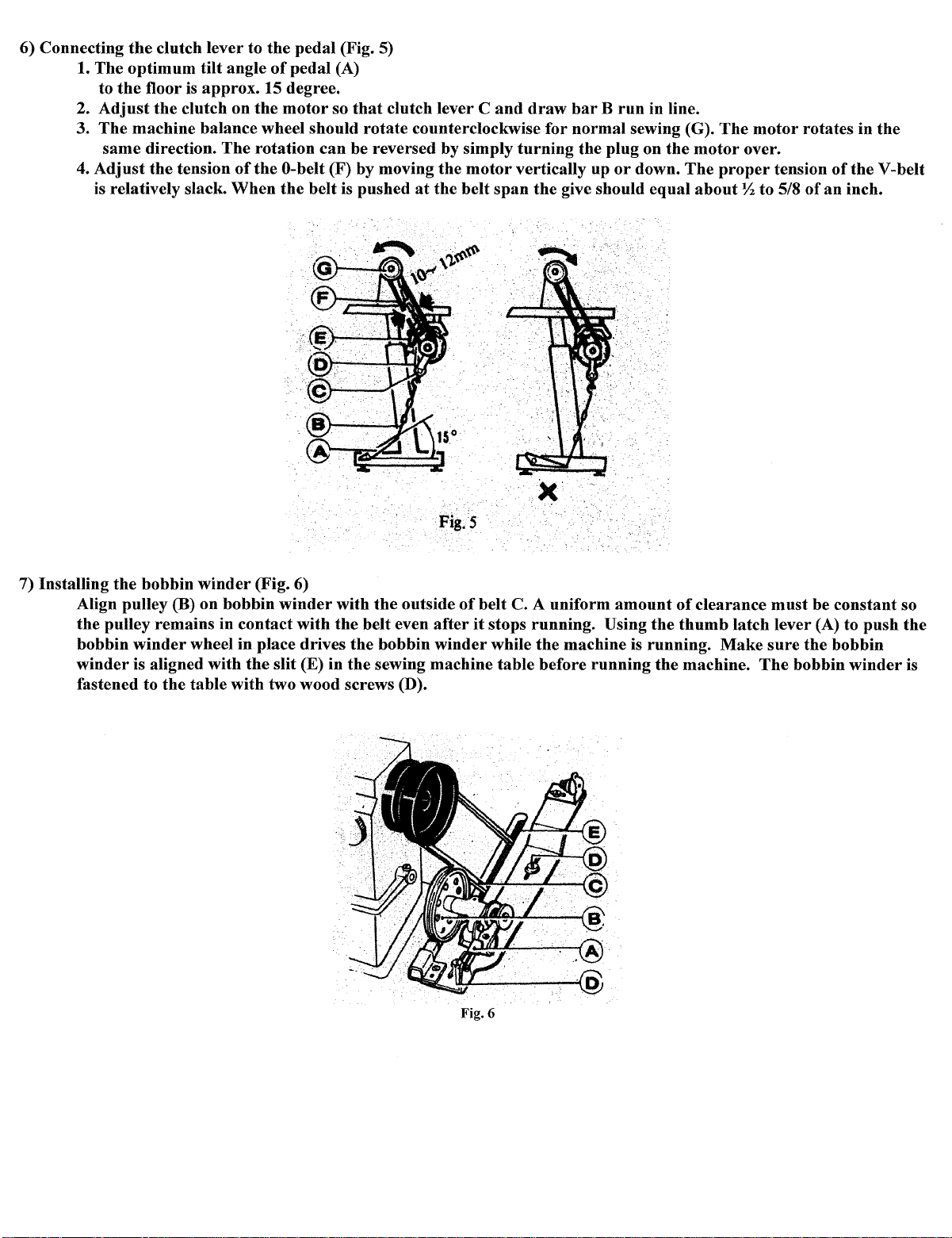
6) Connecting
The
1.
to
2.
Adjust
The
3.
same
Adjust
4.
is relatively slack.
the
clutch lever to
optimum
the
floor is approx. 15 degree.
the
clutch on
tilt angle
the
pedal (Fig. 5)
of
pedal (A)
the
motor
machine balance wheel should
direction.
the
The
tension
rotation
ofthe
When
can
0-belt (F) by moving
the
belt is pushed
so
that
clutch lever C
rotate
counterclockwise for
be reversed by simply
the
motor
at
the
belt
and
draw
turning
vertically up
span
the
barB
run
in line.
normal
the plug on
sewing {G).
the
or
down.
give should equal
motor
The
about
The
motor
over.
proper
Yz
to 5/8
rotates in
tension
of
of
an
the
inch.
the
V-belt
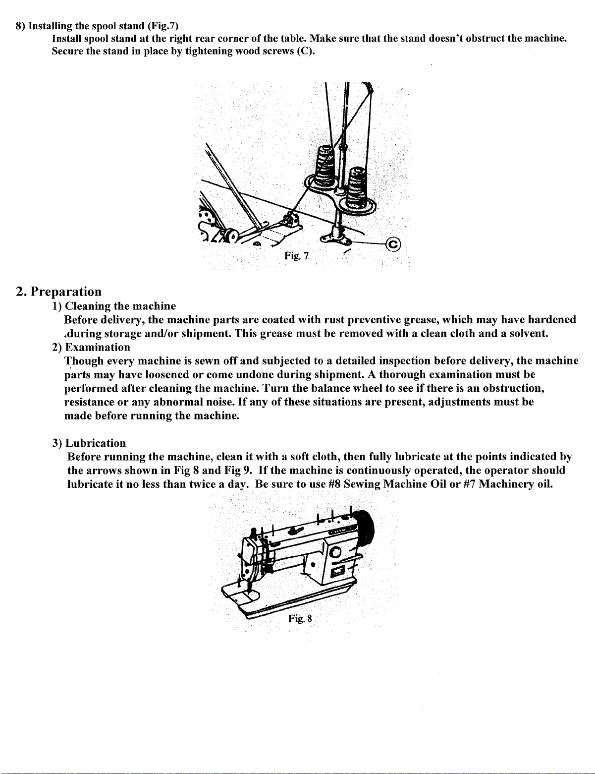
7) Installing
Align pulley
the pulley remains in contact with
bobbin
winder
fastened to
the
bobbin
(B) on bobbin
winder
wheel in place drives
is aligned with
the
table with two wood screws (D).
winder
(Fig. 6)
winder
the
slit (E) in
Fig.5
with
the
outside
the
belt even
the
bobbin
the
sewing machine table before
of
belt C. A uniform
after
it
stops running. Using
winder
while
amount
the
machine is running.
running
the
the
of
thumb
clearance
latch lever (A) to
Make
machine.
must
sure
The
be constant so
push
the
bobbin
bobbin
winder
the
is
Fig.6
Page 8
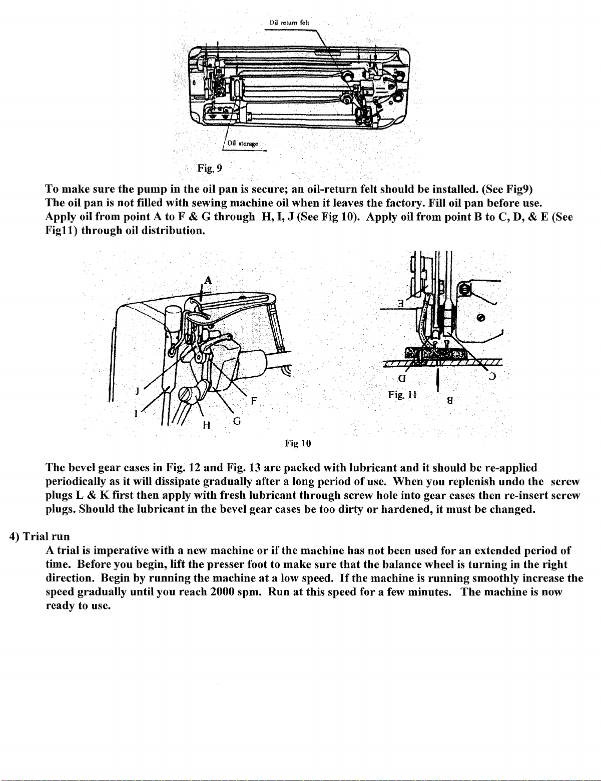
8) Installing
Install spool
Secure the
2.
Preparation
1) Cleaning
Before delivery,
.during
2) Examination
Though
p'arts may
performed
resistance
made
the
spool
stand
(Fig.7)
stand
at
the
right
rear
stand
in place by tightening wood screws (C).
the
machine
the
machine
storage
and/or
shipment. This grease
every machine is sewn off
have
after
or
before
loosened
cleaning
any
abnormal
running
or
the
the
machine.
corner
parts
come
undone
machine.
noise.
If
of
the
table.
Make
sure
that
the
stand
doesn't
are
coated
and
subjected to a detailed inspection before delivery,
Turn
any
with
rust
must
be removed
during
of
these situations
shipment. A
the
balance wheel to see
preventive grease, which
with
a clean cloth
thorough
are
present,
examination
if
there
is
adjustments
obstruct
may
have
and
a solvent.
must
an
obstruction,
must
the
machine.
hardened
the
be
be
machine
3)
Lubrication
Before
the
arrows
lubricate
running
shown
it
no less
the
machine, clean
in
Fig 8
than
twice a day. Be
and
it
Fig 9.
with
a soft cloth,
If
the
sure
then
fully lubricate
at
the
machine is continuously operated,
to use #8 Sewing Machine Oil
Fig.8
or
points indicated by
the
operator
#7
Machinery
should
oil.
Page 9
To
make
The
oil
sure
pan
is
the
not
pump
filled
in
with
Apply oil from point A to F
Figll)
through
oil distribution.
Fig.9
the
oil
pan
is
secure;
sewing machine oil
& G
through
H,
Oil return feb
an
oil-return felt should be installed. (See Fig9)
when
it
leaves
the
factory. Fill oil
pan
before use.
I, J (See Fig 10). Apply oil from point B to C, D, & E (See
4)
The
bevel
gear
cases
in
it
periodically as
plugs L
plugs. Should
Trial
run
A
trial
& K first
is imperative
will dissipate gradually
the
time. Before you begin, lift
direction. Begin by
Fig. 12
then
apply
lubricant
with
running
and
with
in
the
a new machine
the
presser
the
speed gradually until you reach 2000 spm.
ready
to use.
Fig. 13
fresh
bevel
lubricant
gear
foot to
machine
Fig 10
are
packed
after
a long period
through
cases be too
or
if
the machine has
make
at
a low speed.
Run
at
this speed for a few minutes.
with
lubricant
of
screw hole into
dirty
sure
that
If
the
Fig.ll
and
use.
When
or
hardened,
not
been used for
the
balance wheel is
machine is
it
should be re-applied
you replenish
gear
cases
it
must
an
turning
running
The
undo
then
re-insert screw
be
changed.
extended period
in
smoothly increase
machine
the
the
is
screw
of
right
the
now
Page 10
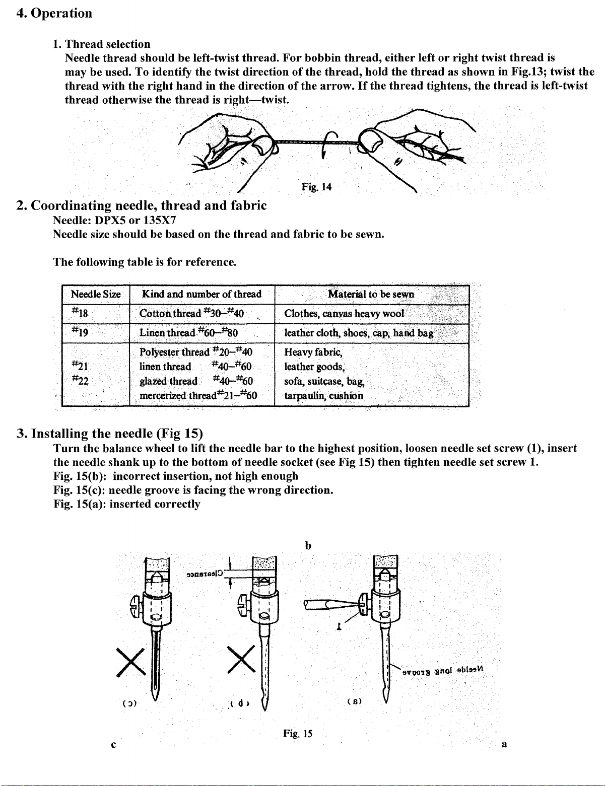
4.
Operation
1.
Thread
Needle
may
thread
thread
2.
Coordinating
Needle: DPX5
Needle size should be based
The
following table is for reference.
selection
thread
be
used.
with
otherwise
needle,
should be left-twist
To
the
or
identify
right
the
thread
135X7
the
hand
thread
on
in
and
thread.
twist direction
the
direction
is
ri~ht-twist.
For
of
of
bobbin
the
the
Fig. 14
fabric
the
thread
and
fabric to be sewn.
thread,
thread,
arrow.
hold
If
the
either
the
thread
thread
left
or
right
twist
thread
as shown in Fig.13; twist
tightens,
the
thread
is
is
left-twist
the
Needle
~1
·~2·
3. Installing
Turn
the
the
needle
Fig. 15(b ): incorrect insertion,
Fig. 15(c): needle groove is facing
Fig. 15(a): inserted correctly
Size
Kind and number
cottoxt'
)>oly~~er
. linen
thread
thread #2o-#40
thr~d
gtazedthread
.mercerlze,d
the
needle (Fig 15)
balance wheel to lift
shank
up
to
the
of
thread
~~#40
#40-:#60
#40-:#60
thread#2t-#60
the
needle
bottom
of
needle socket (see Fig 15)
not
high enough
the
wrong
..
Heavy
fabric,
leather
sofa~.suitcase,
tarpaulin,
bar
to
direction.
goods,
ba~
eu.sltion
the
highest position, loosen needle set screw (1),
b
··
then
tighten needle set screw 1.
insert
X
( :>)
Fig.
15
c
a
Page 11
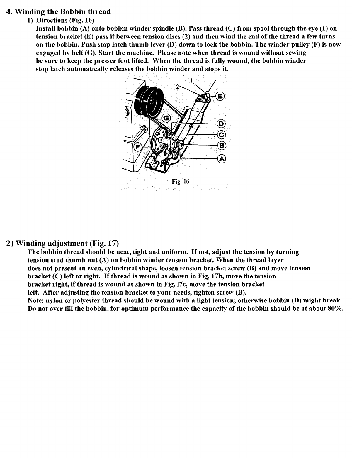
4. Winding
1)
Directions (Fig. 16)
Install
tension
on
engaged by
be
stop latch automatically releases
the
Bobbin
bobbin (A) onto
bracket
the
bobbin.
belt
sure
to keep
thread
(E) pass
Push
stop latch
(G).
Start
the
presser
bobbin
it
winder
between tension discs (2)
thumb
the
machine. Please note
foot lifted.
spindle (B). Pass
lever (D) down to lock
When
the
bobbin
the
thread
winder
Fig.
16
thread
and
then
when
is
and
stops it.
.
(C) from spool
wind the
the
bobbin.
thread
fully wound,
is
wound
end
The
the
through
of
the
thread
winder
without
bobbin
the
eye (1) on
a few
turns
pulley (F) is now
sewing
winder
2) Winding
The
bobbin
tension
does
not
bracket
bracket
left.
After
Note: nylon
Do
not
adjustment
thread
stud
thumb
present
(C) left
right,
over fill
an
or
right.
if
thread
adjusting
or
polyester
the
(Fig. 17)
should be
nut
even, cylindrical shape, loosen tension
the
bobbin,
(A) on
If
thread
is
wound
tension
thread
for
neat,
tight
and
uniform.
bobbin
bracket
should be wound with a light tension; otherwise
optimum performance
winder
is
wound
as shown
to
tension bracket.
as shown in Fig, 17b, move the tension
in
Fig.
your
needs, tighten screw (B).
17c,
If
move
the
not,
adjust
When
bracket
the
tension
capacity
the
tension
the
thread
screw (B)
bracket
of
the
bobbin
by
turning
layer
and
move tension
bobbin
should be
(D) might
at
about
break.
80%.
Page 12
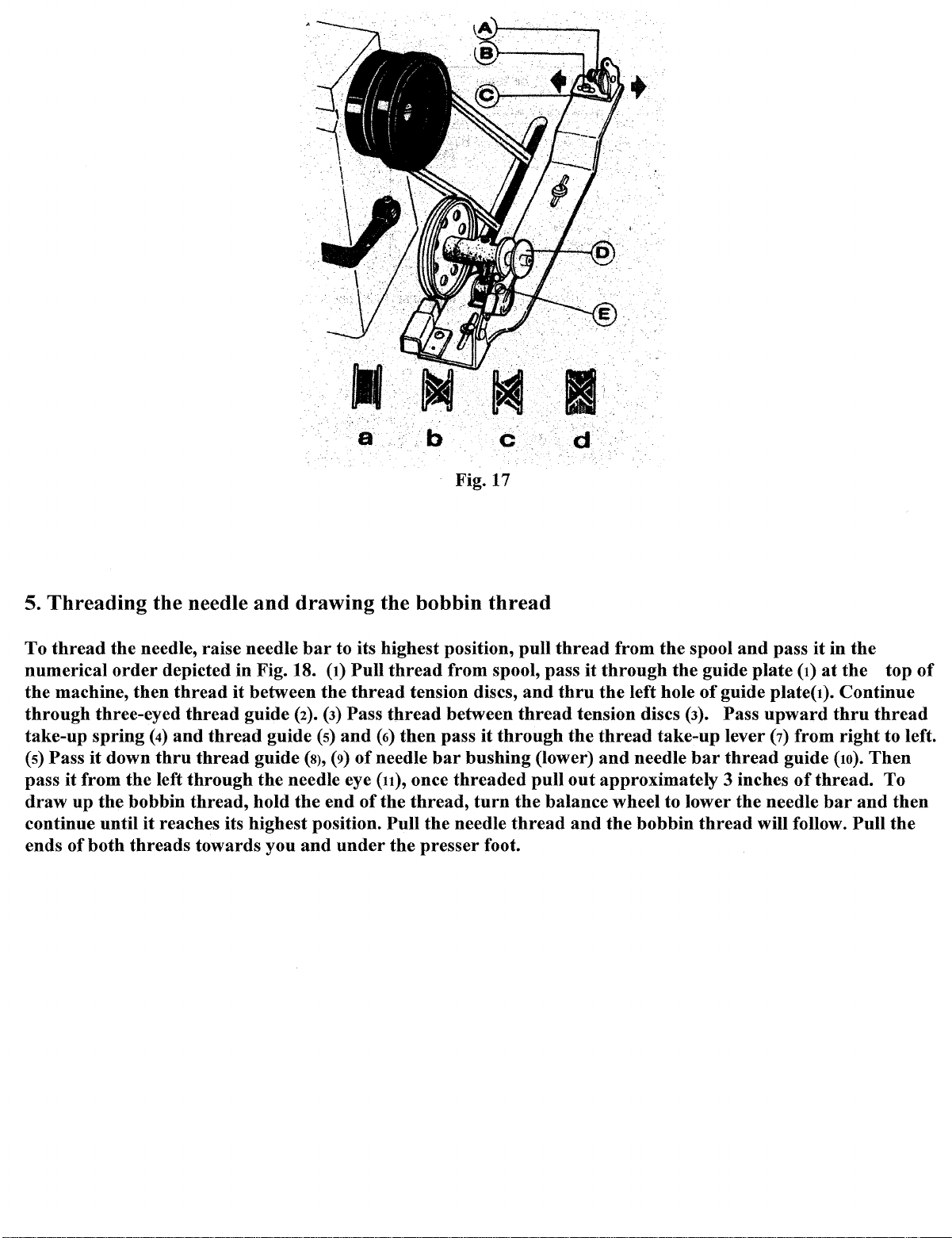
5.
Threading
To
thread
numerical
the
machine,
through
take-up
(s)
Pass
pass
draw
continue until
ends of
the
three-eyed
spring
it
down
it
from
up
the
both
order
the
bobbin
threads
the
needle
needle, raise needle
depicted in Fig. 18.
then
thread
thread
(4)
and
thru
thread
left
through
thread,
it
reaches its highest position.
towards you
and
it
between
guide
thread
hold
drawing
(2).
guide
guide
the
needle eye
the
bar
(s)
(s),
and
b c
Fig. 17
the
bobbin
to its highest position, pull
(1)
Pull
thread
the
(3)
Pass
and
(9)
end
under
thread
of
of
tension discs,
thread
(6)
then
pass
needle
(11),
the
once
thread,
Pull
the
bar
the
presser
thread
from spool, pass
between
it
through
bushing
threaded
turn
needle
thread
foot.
d
thread
and
thru
thread
(lower)
pull
the
balance wheel to lower
from
the
it
through
the
left hole
tension discs
the
thread
and
out
approximately 3 inches
and
the
take-up
needle
bobbin
spool
the
(3).
and
pass
it
in
guide
of
bar
thread
plate
(1)
at
the
guide plate( I). Continue
Pass
upward
lever
(7)
thread
the
needle
will follow.
guide
from
of
thread.
bar
thru
right
(10).
the
thread
Then
and
Pull
top
of
to left.
To
then
the
Page 13
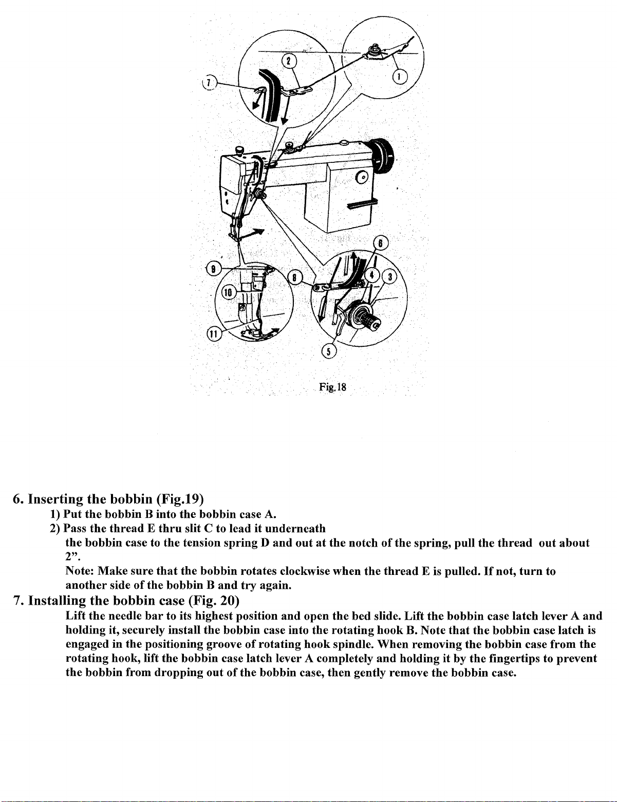
6.
Inserting
1)
Put
2) Pass
the
2".
Note:
another
7. Installing
Lift
holding it, securely install
engaged in
rotating
the
the
bobbin
the
bobbin B into
the
thread E thru
bobbin
the
the
bobbin
case to
Make
side
bobbin
needle
the
hook, lift
from
sure
(Fig.19)
the
bobbin case A.
slit C to lead
the
tension
that
the
bobbin rotates clockwise when
of
the
bobbin B
case (Fig. 20)
bar
to its highest position
the
positioning groove
the
bobbin
dropping
out
Fig.l8
it
underneath
spring D and
and
try
again.
bobbin case into
of
rotating
case latch lever A completely
of
the
bobbin case,
out
and
at
open
the
hook
the
notch
the
bed
rotating
spindle.
then
gently remove
of
the
the
thread
slide. Lift
hook
When
and
holding
spring, pull
E is pulled.
the
bobbin
B. Note
removing
that
it
by
the
bobbin case.
the
thread
If
not,
turn
case latch lever A
the
bobbin
the
bobbin case from
the
fingertips to
out
about
to
and
case latch is
the
prevent
Page 14
·Fig.
'.
19
Fig. 20
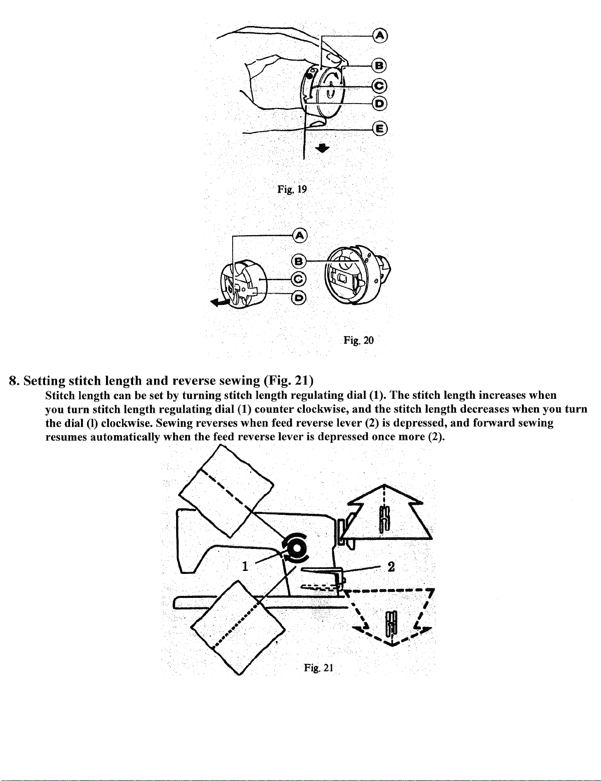
8. Setting stitch length
Stitch length can be set by
you
turn
stitch length regulating dial (1)
the
dial
(I)
clockwise. Sewing reverses
resumes automatically
and
reverse sewing (Fig. 21)
turning
stitch length regulating dial (1).
counter
when
when
the
feed reverse lever
The
stitch length increases
clockwise,
and
the
stitch length decreases
feed reverse lever (2) is depressed,
is
depressed once
more
(2).
2
Fig.
21
.
and
forward
when
when
sewing
you
turn
Page 15
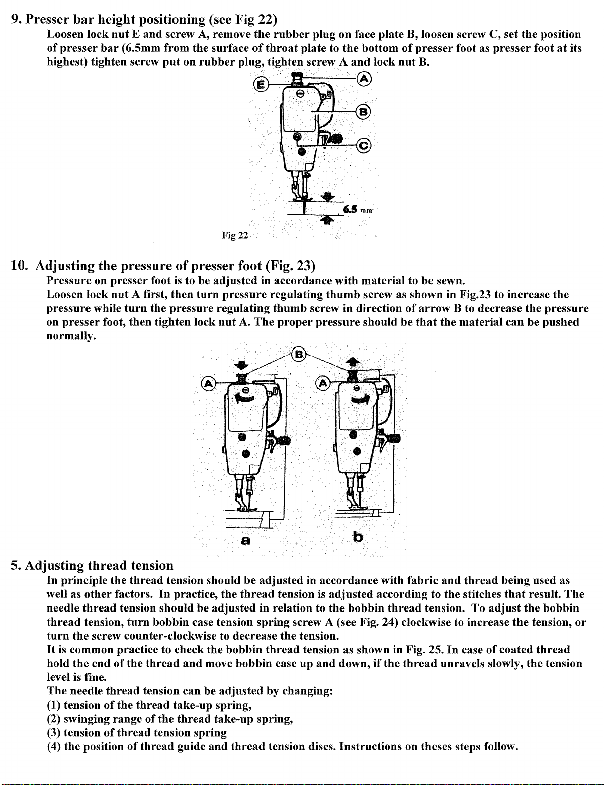
9.
Presser
bar
height positioning (see Fig 22)
Loosen lock
of
presser
highest) tighten screw
nut E and
bar
( 6.5mm
screw A, remove
from
the
surface
put
on
rubber
plug, tighten screw A
Fig22
the
of
rubber
throat
plug
plate to
on face
the
bottom
and
plate
lock
1=1-'-...........__,®
B, loosen screw C, set
of
nut
presser
B.
foot as
presser
the
foot
position
at
its
10. Adjusting
Pressure
Loosen lock
pressure
on
presser
normally.
the
on
presser
nut
while
foot,
pressure
foot is to
A first,
turn
the
then
tighten lock
of
presser
be
then
turn
pressure
foot (Fig. 23)
adjusted
pressure
regulating
nut
A.
The
in accordance
regulating
thumb
proper
thumb
screw in direction
pressure
with
material
screw as shown
should
to
of
be
be
sewn.
arrow
that
in
Fig.23 to increase
B to decrease
the
material
can
the
pressure
be
pushed
the
5. Adjusting
In
well as
needle
thread
turn
It
hold
level is fine.
The
(1) tension
(2) swinging
(3) tension
(4)
thread
principle
other
thread
tension,
the
screw counter-clockwise to decrease
is common practice to check
the
end
needle
the
position
tension
the
thread
factors.
tension should
turn
bobbin
of
the
thread
thread
of
of
the
thread
range
thread
of
tension
of
tension
thread
tension should
In
practice,
be
case tension
and
can
take-up
the
thread
spring
guide
the
adjusted
the
bobbin
move
be
bobbin
adjusted
spring,
take-up
and
thread
be
adjusted
thread
in
relation to
spring
thread
by
spring,
tension discs.
in accordance
tension is
screw A (see Fig. 24) clockwise to increase
the
case
changing:
adjusted
the
tension.
tension as shown
up
and
down,
Instructions
according
bobbin
if
with
fabric
thread
in
Fig. 25.
the
thread
on theses steps follow.
and
to
the
tension.
In
case
unravels slowly,
thread
stitches
To
adjust
of
being used as
that
result.
the
bobbin
the
tension,
coated
thread
the
tension
The
or
Page 16

Fig. 24
Strong
1.
Adjusting
The
thread
spring
spring
(1) Adjusting
the
thread
normal
Loosen tension
the
tension
take-up
tension
tension
the
tension
take-up
of
the
spring
and
and
stud
is
widen
shorten
thread
stud
set screw A,
counter-clockwise to decrease
spring
thread
5-Smm.
the
range
the
range
take-up
take-up
For
spring
tighten tension stud set screw A.
25
Fig.
spring
is approx. 25-35g.
The
sewing light weight materials (with a
of
the
of
spring.
the
spring.
For
sewing heavier weight materials,
tension (Fig. 26)
turn
tension
stud
B clockwise to increase
the
spring
tension.
After
normal
short
the
the
swing
range
of
the
stitch length), lessen
strengthen
spring
adjustment,
tension,
be
sure
or
the
the
turn
to
Fig. 26
Page 17

(2)
Adjusting
The
thread
stud B counter
take-up
spring
clockwise to release
B counter-clockwise until
regulator,
then
turn
tension
set screw A.
the
swing
Loosen set screw B,
clockwise to decrease
Re-adjustment
range
of
turn
the
is needed only in
tension is
spring C just
stud
about
the
30g.
tension
of
comes into
B clockwise by
To
attain
thread
contact
another
this, loosen set screw A first,
take-up
with
the
1 /2
turn.
Fig.27
thread
take-up
spring
(Fig. 27).
tension complete C clockwise to increase
swing range. Before delivery,
the
case
of
sewing special
thread
materials
take-up
spring
stopper
After
the
swing
or
C to zero.
on
thread
adjustment,
range
spring
with
is
special
then
Turn
tension
take-up
tighten tension
or
turn
properly
thread.
turn
tension
stud
spring
it
counter-
adjusted.
stud
2. Adjusting
The
position
materials
guide
Thread
Position
Material
and
guide
weight
the
thread
of
the
being sewn
the
materials to
guide
thread
and
guide affects
the
sewing conditions.
be
sewn is
•••
illustrated
·.I
Left
sewing quality
The
normal
in
the
following table.
•.
Center
·~
MediUB1
and
must
be
adjusted
relationship between
3
Ri$ht
r~•
,~.
I
.-
__
,,__.,._._
Light.
r
according
the
position
to
of
the
the
thread
Page 18

3. Adjusting the tension
Fig. 28 shows
When
adjusted
1)
If
the
nut
counterclockwise to decrease
increase
If
the
2)
clockwise to increase
clockwise to decrease
If
the
3)
stitches
needle
the
bobbin
needle
stitches
the
various types
are
puckered, loose,
accordingly.
thread
thread
appear
tension
thread
tension is too low
the
needle
the
bobbin
as shown in Fig. 28( d), (e),
of
needle
is
too high
the
tension (see Fig. 29).
thread
thread
thread
of
stitch
or
the
or
bobbin
needle
thread
or
bobbin
tension
tension (see Fig. 30).
and
bobbin
patterns.
thread
thread
tension
thread
or
turn
the
adjustments
thread
Normal stitches should
breaks,
the
tension
of
needle
appear
and
as shown
b
.C
d
e
tension is too low,
or
tighten
is
too high,
bobbin case tension regulating screw
can
be
the
turn
made
turn
the
bobbin
the
case tension regulating screw to
tension regulating
by following
tension regulating
bobbin
counter-
the
above steps.
in
Fig. 28(a).
thread
thumb
must
thumb
nut
be
Page 19

Fig.
29
6. Machine
Timing between needle
1) Adjusting
Turn
the face plate,
bring
clamping screw B
Adjustment
and
the
needle
the
balance wheel to position
A.
Loosen needle
the
center
of
bar
needle eye, D
and
replace
rotating
hook
motion
position (Fig. 31)
the
needle
bar
C connecting
match
rubber
up
plug.
with
Fig. 30
bar, C at
stud
the
inside surface
its lowest position. Remove
the
clamping screw B. Move needle
of
rotating
hook
E.
rubber
bar
C vertically to
Then
tighten
plug
from
Fig. 31
Fig.32
Page 20

2) Adjusting
Turn
the
balance wheel to position
lifted again
center line C,
rotating
at
2.5
mm
and
hook
hook
point
timing with needle (fig. 33)
the
needle
from its lowest position,
point
D should be 1.2mm above
bar
the
Fig.33
at
its lowest position,
rotating
the
hook
point D should coincide with needle
upper
edge E
and
when
of
needle eye.
the
needle
bar
is
When
of
3) Removing
Lift
the
Loosen
the
two set screws D on
from
colliding
slowly.
To
adjusting
needle D
and
needle
rotating
with
install
the
rotating
and
hook
point C must
installing
bar
to its highest position. Remove
hook
the
bobbin case
rotating
the
feed dog
the
rotating
hook
hook
rotating
holder
hook.
support
follow
hook
At
point timing also note
be
constant
at
approximately 0.05mm (see Fig. 34).
Fig. 34
(Fig. 35)
the
position
bracket
this point, the
since
the
feed dog
the
above sequence
throat
plate
screw C
hook
support
that
will
in
reverse.
the
clearance between
and
take
out
and
take
down position
turn
freely on its shaft,
is
at
its highest. Remove
the
needle
the
and
the
bracket
and
it
the
notched
bobbin
A. Loosen
can
be
rotating
bottom
case.
kept
hook
Fig.
35
Page 21

2.
Adjusting
1) Adjusting
the
feed dog
the
height
Turn
teeth should be
above
balance wheel to raise
the
throat
of
the
feed dog
0.8-lmm
plate surfaces
above the
the
feed dog to its highest position,
it
throat
is
the
plate surface.
ideal height for sewing heavy material.
If
the
at
that
height
position,
of
the
the
height
feed dog teeth
of
feed dog
islmm
When
lifting
clamping screw A.
2) Adjusting
the
throat
plate
. . . . . . .
~'~ffl!l.t
adjusting, loosen feed lifting
rock
shaft
the
position
slit end to
crank
B till
the
of
feed dog (Fig. 37)
the
front
end
rock
proper
The
of
the
~
f
0.8mm-Imm
shaft
crank
height
Fig. 36
standard
fully advanced feed dog
clamping screw A (Fig. 36) slightly,
of
the
feed dog teeth is achieved,
position
of
feed dog A is
is
1.5 mm.
after
that
then
adjustment,
the
clearance
turn
from
feed
tighten
2)Max the feed dog to
ping
screws. Move feed dog
ment, tighten clamping screw.
the
3 Adjusting
The
tension discs should be pushed
tension discs can
lever (left).
open earlier
tension release mechanism (Fig. 38)
Then
when
the
position
support
be
adjusted. Remove
the
tension releasing cam can be moved left
the cam
is
where
to
adjust
apart
the
moved left.
Fig. 37
the feed dog fully advances. Loosen two feed
the
to open
rubber
clearance between
when
plug
the
at
the
presser
rear
or
the
feed dog
foot
is
lifted.
of
arm
and
right, open
and
But
loosen screw A
later
when
rock
shaft
throat
the
open timing
the
cam
crank
plate. After
of
the
is moved right,
clam
of
the
knee lifting
adjust-
Fig.38
Page 22

7. Cleaning
1) Cleaning
Remove
2) Cleaning
Brush
the
the
the
feed dog (Fig. 39)
throat
the
hook
rotating
plate
and
wipe
Fig. 39 Fig. 40
and
hook
the
clean off all the
dust
and
(Fig. 40)
bobbin case with a soft cloth.
lint on
the
feed dog
with a brush.
Page 23

8.
Trouble
shooting
Trouble
Needle
breaking
Stitches skip
Needle thread
Breaking
Possible causes
1. Needle
2.
Needle
Operator
3.
the material.
4.
The weight
1.
2. Needle set incorrectly.
1. Needle threaded incorrectly.
2.
Tension too high.
3. Poor quality
4.
Needle too thin
is
too thin
is
set incorrectly.
pushes
being sewn
Needle
number
weight
is
of
bent
is
or
bent.
or
pulls
of
the material
is
too heavy.
or
the needle
not correct for the
the fabric.
thread
or
too rough.
. Remedy
Change the needle.
Refer to Fig. 15
Do
not push
Do not exceed the technical
Specs
Change the needle.
Refer to Fig. 15
Refer to Fig. 18
Refer to Fig. 29
Change the thread
Change the needle
or
of
the machine
pull the fabric.
Bobbin thread
breaking
Loose
stitches
Puckering
1. The bobbin
tension
2.
Thread
is
loose and uneven.
3. Needle hole on
is
rough
1.
Incorrect tension level on thread
and bobbin
2. Tension too low on thread tension
spring
1. The weight
is
too light, the stitch length
too long
2.
The tension on the needle
and bobbin
thread
is
too high
on bobbin
throat
or
worn.
of
the fabric
is
too high
plate
Lessen the bobbin thread tension
Re-wind the bobbin
throat
plate
or
Change
needle hole with emery cloth
Re-adjust tensions
Adjust the tension on
take-up spring-Fig. 26
Adjust accordingly
Adjust tension regulating
thread take-up spring and bobbin case
tension spring screw.
polish
thread
thumb
nut,
3. Pressure on presser foot too high
Loosen pressure regulating
thumb
screw.
Page 24

Parts
Catalogue
Page 25

1.
11
~
..
:
~······.
:.~
42
. '
' I
46'1):
. r
..
?·
.
f
f.,
f
I
I
I
I
I
I
I
I
Page 26

1.
Arm
and
Bed
Item
1.
2.
3.
4.
5.
6.
7.
8.
9.
10. Face plate 1
11.
12.
13.
14.
15.
16.
17.
18.
19.
20.
21.
22.
23.
24.
25.
26.
27.
28.
29.
30.
31.
32.
33.
34.
35.
36.
37.
38.
39.
40.
41.
42.
43.
44. Spring 1
45.
46.
47. Position finger for oil wick
48.
49. Cover 1
50.
51.
Description
Machine Bed 1
Machine
Screw 2
Screw 1
Screw
Pin
Name plate 1
Trade
Nail
Rubber
Rubber
Rubber
Rubber
Rubber
Thread
Screw
Screw 1
Screw 3
Rear
Screw
Washer
Screw 1
Spring
Thread
Shim 1
Split stop ring
Thread
three-eye
Screw 1
Oil pipe 1
Nut
Stop plate 1
Spring
Thread
Pin
Discs 2
Screw 1
Thread
Thread
Screw 1
0-type ring
Set screw 1
Thread
Throat
Screw 2
Slide plate 1
Screw 2
Oil plug
Seal ring 1
Press plate 1
Screw
Arm
mark
plug (M9) 1
plug (N9
plug 2
plug 1
plug 1
Finger 1
cover
tension discs 2
guide plate 1
thread
tension releasing plate 1
take--up
tension adjusting
finger 1
plate
finger 1
spring
bracket
#of
Pieces
1
1
2
1
4
1
1
1
6
6
1
1
1
1
1
1
1
1
1
2
1
4
Page 27

2.
e-2.2
I
'
26
27
28
. I
.:
..
.a--
21.
I
I
I'
I
I
I
'
I
I
I
I
I
I
:
.24
I
J.
I
I
:
23
I
I
l
l .
...
-----
20
.l.
...
.~25
.J
29
19
3.
g;(
.
·.1
.
~.
1;
\1\.·t
·~··
...
··•·
..
··
··~·
...•.
8-~.-
......
~"".
-_
' ·
.··
..........
_>···. J
l7,
.
16
/
.
Page 28

2.
Needle
Bar
and
Thread
Take-up
Item
I.
2.
3.
4.
5.
6.
7.
8.
9.
10.
11.
12.
13.
14.
15.
16.
17.
18.
19.
20.
21.
22.
23.
24.
25.
26.
27.
28.
29.
30.
31.
32.
Description
Thread
Thread
Thread
Thread
Thread
Thread
Thread
Needle
Needle
Needle
Needle
Needle
Thread
Thread
Needle
Needle
Thread
Thread
Needle
Needle
Needle
Needle
Needle
Needle
Needle
Needle
Needle
Needle
Needle set screw
Needle
Needle
Needle
take-up
take-up
take-up
take-up
take-up
take-up
take-up
bearing
bar
connecting
bar
connecting link
bar
connecting stud
bar
connecting
take-up
take-up
bar
crank
bar
crank
take-up
take-up
bar
crank
bar
bushing
bar
bushing
bar
bushing
bar
bushing (lower)
bar
bushing (lower) set screw
bar
bushing (lower)
bar
bar
thread
bar
connecting stud slide block guide-way
bar
connecting
bar
connecting
crank
lever
lever eyelet bushing
lever link
lever link oil wick
lever
link
hinge pin
lever
link
hinge pin set screw
link
cap
screw
stud
clamping screw
lever
guard
lever
guard
screw
set screw
crank
clamping screw:
crank
position screw
position screw
(upper)
(upper)
(upper)
guide
set screw
rubber
thread
stud
slide block
stud
slide block guide-way screw
guard
plug
#of
Pieces
1
1
1
1
1
1
1
2
1
1
1
1
1
1
1
1
1
1
1
l
1
l
l
1
1
1
1
1
1
1
1
1
Page 29

3.
' '
'
:
10
I
,
' .
I I
\21'f?!
. .
' '
'
23\.\
~-~··.,.
fQbP
' I
12'
..
·(}.
..
~
.
..,_12
' : :
L.!3
'
c4f.
22
f '
f
... :
25
I
I
Page 30

3.
Arm
Shaft
and
Vertical
Shaft
Item
1.
2.
3.
4.
5.
6.
7.
8.
9.
10.
11.
12.
13.
14.
15.
16.
17.
18.
19.
20.
21.
22.
23.
24.
25.
Description
Arm
shaft
Arm
shaft
flanged
Arm
shaft
bushing
Arm
shaft
bushing
Arm
shaft
bushing
Arm
shaft
collar 1
Arm
shaft
collar set screw 2
Feed dog
Feed
Screw 2
Arm
Bevel
Bevel
Arm
Arm
Balance wheel 1
Balance wheel set screw 2
Arm
Vertical
Vertical
Vertical
Vertical
Rotating
Bevel
Vertical
fork
cam
shaft
bevel
gear
set
gear
case
shaft
bushing
shaft
bushing
shaft
screw 1
shaft
shaft
shaft
shaft
hook
gear
case (lower) assembly 1
shaft
bushing
oil
set screw 5
(middle) 1
sliding block complete 1
gear
screw 8
(upper)
(rear)
(rear)
bevel
gear
bushing
bushing
bevel
gear
shaft
bevel
(front) 1
pad
(felt) 3
complete 1
oil sea1asembly 1
(upper)
(upper)
(lower) 1
(lower) 1
gear
#of
Pieces
1
1
1
1
1
1
1
1
Page 31

4.
·~.
I
14_j
Page 32

4. Rotating
Hook
and
Shaft
Item
1.
2.
3.
4.
5.
6.
7.
8.
9.
10.
11.
12.
13.
14.
Description
Hook
Collar
Screw
Rear
Felt
Screw
Front
Felt
Hook
Screw
Bobbin
Bobbin
Position finger
Screw
shaft
complete
for
hook
bushing
bushing
complete
case, complete
shaft
#of
pieces
1
1
2
1
1
1
1
1
1
3
1
1
1
1
Page 33

5.
Page 34

5. Stitch Length Regulating
Item
1.
2.
3.
4.
5.
6.
7.
8.
9.
10.
11.
12.
13.
14.
15.
16.
17.
18.
19.
20.
21.
22.
23.
24.
25.
26.
Description
Stitch length dial
Stitch length
Screw
Rubber
Stop
pin
Spring
0-type
Stitch length adjusting swing
Set screw
Hinge
pin
Screw
Stitch
length
Pin
Set screw
Reverse feed swing lever, complete
Screw
Shaft
for feed lever
Screw
Reverse feed lever
Set screw
Set screw
Reset lever
Screw
Coil spring
Set
hook
Screw
plug
ring
for
adjusting
link
spring
screw
bar
bar
#of
pieces
1
1
1
1
1
1
1
1
1
2
1
1
1
1
1
1
1
2
1
1
1
1
1
1
1
1
Page 35

6.
17
. '
'
•
. '
r·..,~--..
..
.,
'
~
I J '
, . .
t • t
I '
I
~
29.
Page 36

6. Bottom Feed
Item
Mechanism
Description
#of
pieces
1.
2.
3.
4.
5.
6.
7.
8.
9.
10.
11.
12.
13.
14.
15.
16.
17.
18.
19. Collar
20.
21.
22.
23.
24.
25.
26.
27.
28.
29.
30.
31.
32.
Feed cam
Screw
Fork
slide block, complete 1
Fork
crank
Feed
Screw
Pin
Set screw
Feed shaft
Front
Rear
Screw
Collar
Screw
Stop
ring
Stop
ring
Front
Feed dog
Screw
Feed dog
Screw
Feed dog
Screw
Link
Screw
Nut
Shaft
Oil wick
Feed dog lift
Screw 1
Nut
bushing
bushing
for
arm
shaft
crank
for feed dog lift 1
for feed
shaft
support
crank,
complete 1
1
2
1
1
1
1
2
1
1
1
2
1
2
1
1
1
1
1
2
1
2
1
2
1
1
1
2
1
Page 37

7.
8
~-,
..
9
lo .
~
Page 38

7.
Presser
Bar
Item
1.
2.
3.
4.
5.
6.
7.
8.
9.
10.
11.
12.
13.
14.
15.
16.
17.
18.
19.
20.
21.
22.
23.
24.
25.
26.
27.
28.
Description
Presser
Presser
Presser
bar
lifter
bar
lifter position screw
bar
lifting
cam
Knee lifter lever (left)
Tension releasing
Knee
lifter lever (left) screw
Knee
lifter
link
Knee
lifter
link
Tension releasing
Tension releasing
Knee
lifter lever (left) (right)
Knee
lifter lever (left) (right)
Knee
lifter lever (left) (right) hinge screw
Knee lifter lifting
Knee
lifter bell
Presser
Presser
Presser
bar
bar
bar
bushing
bushing
cam
hinge screw
cam
hinge screw
rod
rod
crank
(right)
set screw
Screw
Presser
Presser
Thread
bar
guide
bar
guide
finger
bracket
bracket
set screw
Screw
Reel
for
spring
Presser
Pressure
Pressure
bar
spring
regulating
regulating
thumb
thumb
screw
screw lock
Screw
spring
spring
connecting
nut
#of
pin
pieces
1
1
1
1
1
1
1
2
1
1
1
1
1
1
1
1
1
1
1
1
1
1
1
1
1
1
1
1
Page 39

8.
7~
. I
IO
I
I
I
I
I
Page 40

8.
Lubrication
Item
1.
2.
3.
4.
5.
6.
7.
8.
9.
10.
11.
12.
Description
Oil
wick
fixing
Oil
wick
fixing
Oil
wick
fixing
Oil wick fixing
Wick
Small oil
Small oil
Small oil
Long
Long
Long
Long
for
oil
reservoir
reservoir
reservoir
oil
wick
oil
wick
oil
wick
oil
wick
wick
plate
plate
hook
hook
fixing
screw
oil
fixing
fixing
clamp
assembly
screw
screw
plate
pad
hook
hook
screw
#of
pieces
1
2
1
1
1
1
1
1
1
2
1
1
Page 41

9.
Page 42

9.
Drip
Pan
and
Knee
Lifter
Item
1.
2.
3.
4.
5.
6.
7.
8.
9.
10.
11.
12.
13.
14.
15.
16.
17.
Description
Drip
pan
Nails
Knee lift
Knee lifter
Hexagon
Round
Knee lifter
Knee lifter
Knee lifter
Knee lifter
Knee lifter lifting
Knee lifter bell
Knee lifter bell
Knee lifter
Knee lifter
Knee lifter knee plate assembly
Knee lifter knee plate set screw
pushing
pushing
nut
head
rock
rock
rock
rock
rock
rod
rod
rod
wood screw
shaft
bracket
shaft
spring
shift
spring
shaft
crank
crank
crank
shaft
joint
joint
stop dog
guide
pin
set screw
bushing
#of
Pieces
1
6
1
1
1
4
2
1
1
1
1
4
1
1
1
1
1
Page 43

10.
••
IJ-25
, I
I
18
Page 44

10. Bobbin
Winder
Item
1.
2.
3.
4.
5.
6.
7.
8.
9.
10.
11.
12.
13.
14.
15.
16.
17.
18.
19.
20.
21.
22.
23.
24.
25.
26.
27.
28.
Description #
Bobbin
Bobbin
Bobbin
Bobbin
Bobbin
Bobbin
Bobbin
Bobbin
Bobbin
Bobbin
Bobbin
Bobbin
Bobbin
Bobbin
Bobbin
Bobbin
Bobbin
Bobbin
Bobbin
Bobbin
Bobbin
Bobbin
Bobbin
VVasher 1
Bobbin
Bobbin
Bobbin
VVasher 2
winder
winder
winder
winder
winder
winder
winder
winder
winder
winder
winder
winder
winder
winder
winder
winder
winder
winder
winder
winder
winder
winder
winder
winder
winder
winder
base 1
frame
frame
spring
spring
spindle 1
brake
frame
frame
pulley 1
stop latch
stop latch
rivet 2
stop latch
stop latch 1
brake
brake
tension
tension
tension disc 2
tension
tension
tension
pulley set screw 1
stop latch screw 1
wood screw 2
hinge
stripe
oil
oil
stripe
stripe
pin
plunger
clamping screw 1
wick
wick
thumb
trip
trip
clamp 1
bracket
stud
spring
stud
thumb
bracket
cap 1
lever 1
lever 1
lever hinge screw 1
nut
screw 1
of
pieces
1
1
1
1
1
1
1
1
1
1
Page 45

11.
. I
. I
'I
I · I
I I
,
_____
.
_J
r-----
I
I
I
I
I
I
I
I
I
I
I
I
I
I
I
I
I
I
I.
l
I
I
1
I
I
-----1
19~
7
f-19
17-~~~-~---
.--I lS.
-t-
~---·
Page 46

11. Spool
Stand
Item
1.
2.
3.
4.
5.
6.
7.
8.
9.
10.
11.
12.
13.
14.
15.
16.
17.
18.
19.
Description
Wing
Spring
Thread
Thread
Thread
Thread
Spool
Spool
Spool
Thread
Spool
Spool
Felt
Spool
Spool
Spool
Spool
Spool
Spool
nut
washer
guide position
guide
guide
guide
rest
rest
rest
guide position plate
pin
stand
pad
pin
washer
pin
lock
pin
nut
stand
rest
rod
stand
rod
rod
nut
rod
rod
sleeve
rod
sleeve set screw
washer
nut
wood screw
cup
#of
pieces
1
1
1
2
1
1
1
1
1
1
2
2
2
2
2
2
1
1
3
Page 47

12.
--·~.-<
..
~·
....
' ' .
. . .
•'
-'-"'"' : '
··2
,3
4
I
I
I
8
Page 48

12. Accessories
Item
1.
2.
3.
4.
5.
6.
7.
8.
9.
10.
11.
Description
Arm
Arm
table connecting
Accessory box
Oil
Needle
Triangle
Arm
Bobbin
Screw
Screw
Screw
table connecting
hook
can
belt
vibration
driver
driver
driver
proof
(small)
(middle)
(big)
hook
vibration
washer
block
protection tool
#of
pieces
2
2
1
1
1
1
2
5
1
1
1
 Loading...