

Page 1

104-1T
104-2T
104-3T
PARTS BOOK
AND INSTRUCTION MANUAL
Page 2

INDEX
DESCRIPTON...................................................................................... 2
SPEED ................................................................................................. 4
TO OIL THE MACHINE ........................................................................ 3
NEEDLES, NIPPLES AND THREAD ................................................... 4
TO REMOVE, REPLACE AND SET
NEEDLE AND NIPPLE ............... 5
TO THREAD THE MACHINE ............................................................... 7
LEARNING TO OPERATE THE MACHINE.......................................... 9
TO OPERATE THE MACHINE............................................................. 9
T REGULATE THE PRESSURE ON THE
PRESSER FOOT............... 10
TENSIONS ........................................................................................... 10
TO ADJUST THE LENGTH OF STITCH .............................................. 11
TO REGULATE THE PRESSURE ON
THE NIPPLE ........................... 12
THE LOOPER ...................................................................................... 12
TO SET THE LOOPER ........................................................................ 13
PILE OR MOSS STITCH...................................................................... 14
PARTS LIST ......................................................................................... 15
1
Page 3

DESCRIPTION
Embroidery machine makes the single thread chain stitch and can be
quickl
y adjusted to make the drop or moss stitch without unthreading the
machine. It is designed for ornamenting or embroidering curtains, upholstery,
dresses, scarf, gloves, table covers, lace, etc. The machine also can make
linen and towels for hotels, etc., by stitching a name into the material.
The thread may be of cotton, wool, worsted, si
lk, metal and other threads
of similar adaptability. A large variety of fabrics can be embroidered, ranging
from fine chiffon to china silk and cloth.
The usual method of producing embroidered designs i
s to follow a pattern
that has been perforated, stamped or traced on the fabric, but with practice
the operator can produce embroidery designs without pre-making the fabric.
SPEED
When first operating this machine, the best result s can be obt ained by
running the machi ne at approximately 800 stitches per minute. T he speed
can be increased as the operator become more proficient and the nature of
the work permits.
2
Page 4
TO OIL THE MACHINE
To insure easy running and prevent unnecessary wear of the parts which
are in movable contact, the machine requires oiling.
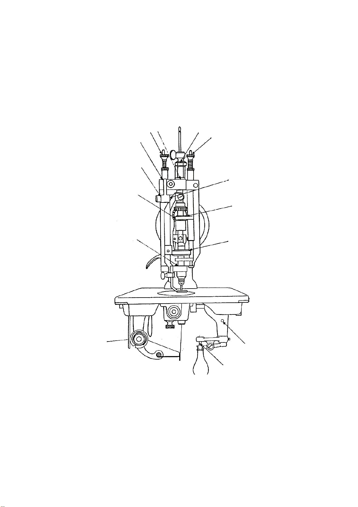
Oil should be applied to the plac es designated by unlettered arrows in
Figs. 1, 2, 9, and 10.
Fig. 1, End view of machine showing oiling points.
3
Page 5
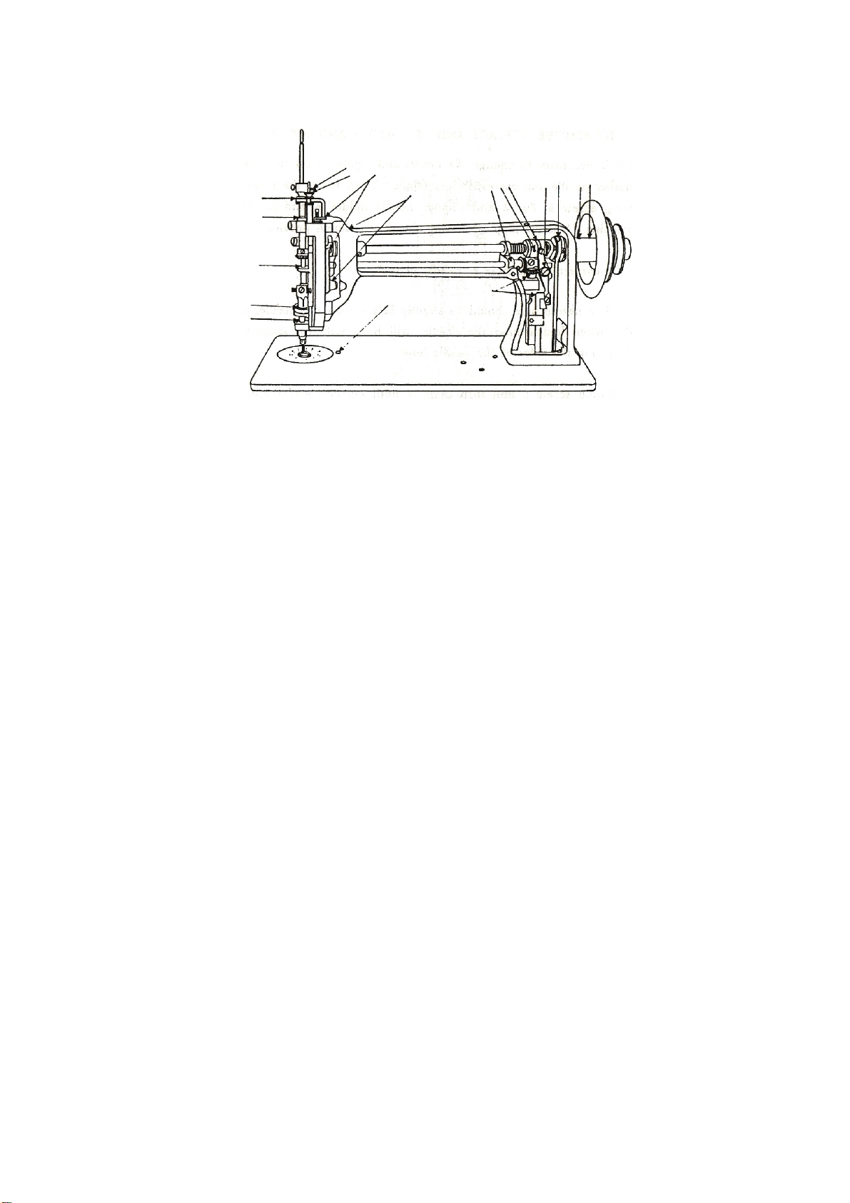
Fig. 2, Oiling points of the front of the machine
Fig. 2 shows the arm cover removed for the purpose of oiling. This arm
cover can be removed after taking out thumb screw W, Fig. 8.
If the machine is used continuously, oil should be applied at least once each
.
day
NIPPLES, NIPPLES AND THREAD
Needles for embroidery machine are catalogue no. 5901 (137 x 1) and
are available in si zes from 1 to 12. These needles have hook similar in
appearance to those of hand crochet needles.
The needle must be selected accordi ng to the thickness and the style of
the thread to be used. The thread m
in the needle but must slide freely therein.
ust not only fill the opening of the hook
To correspond with the needle used in the machine a suitable nipple must
be selected, as the needle in formin g the sti
tch has to operate through the
nipple. The needl e must fit in the ni pple and slide freel y without side pl ay.
Nipples are available in size numbers similar to those of the needles, and
for general work the number of the nipple should be the same as that of the
needle.
4
Page 6

TO REMOVE, REPLACE AND SET NEEDLE AND NIPPLE
When it is necessary to change the needle and nipple on the machine,
first select another n eedle and corresponding nipple. Then lower the
presser bar, loosen wing screw B, Fig. 3 and remove needle hol der A and
needle from top of machine. Unscrew nipple N, using the small wrench
provided.
Select the correct needle hole in needle pl
ate D.
NOTE: The needle hole should be slightly larger than the needle, so that
the needle, when laid around the needle, will have suf
ficient space to pass
without touching the sides of the needle hole.
Loosen thumb screw L and turn plate D until correct needle hol
e is in line
with needle, then tighten thumb screw L.
Next, screw selected ni pple into th e lower end of nipple carrier O and
tighten securely with the small wrench. Screw selected needle into either
end of needle hol
der A and tighten with pliers provided. Repl ace needle
holder A down into sleeve and adj ust its height so that the fabric to be
embroidered can just under the point of the needle.
Be sure handle K is as far to the front as possible and that the hook of the
needle faces the front. Then tighten wing screw B, wh ich also should face
the front.
5
Page 7
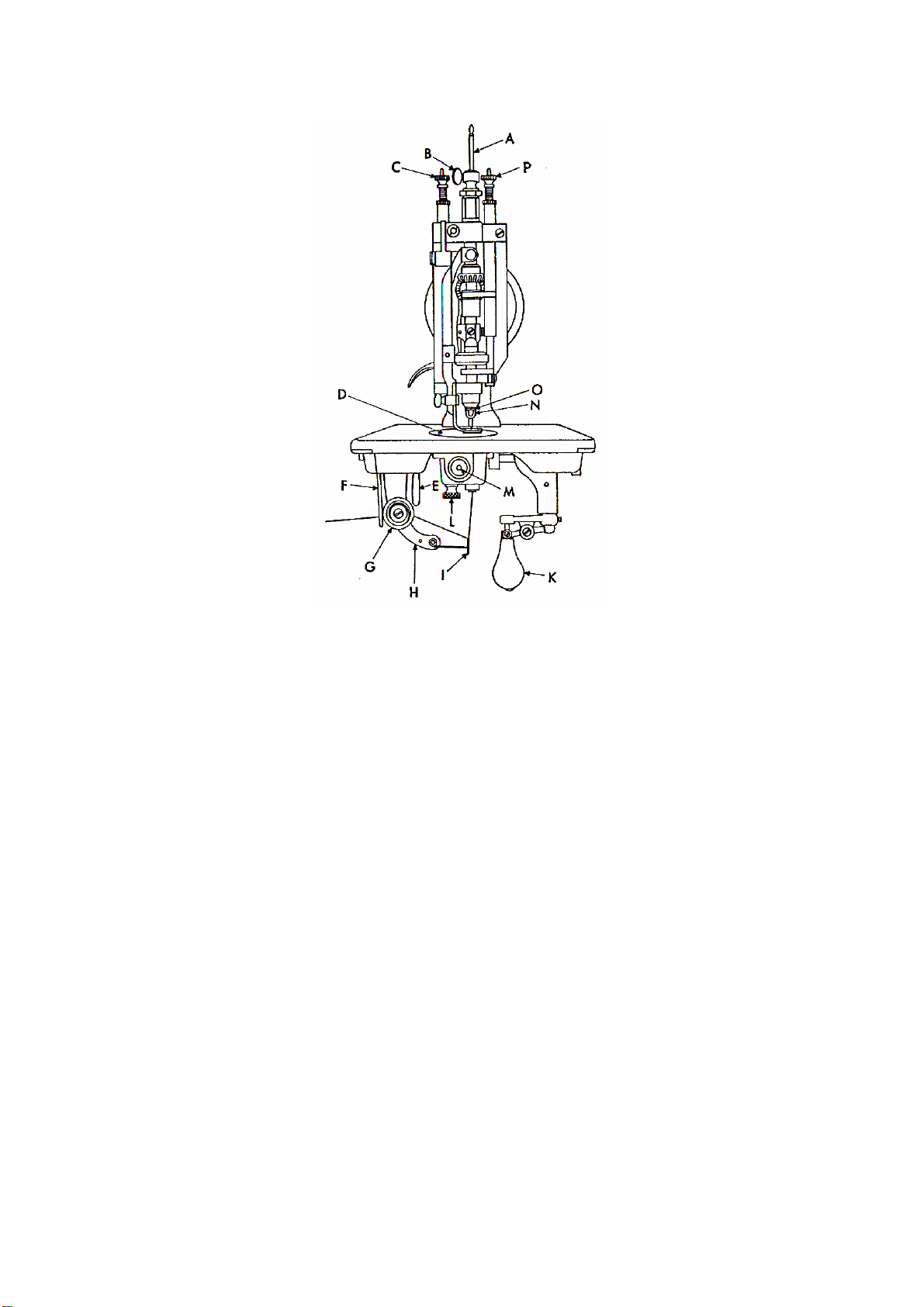
Fig. 3, Adjustments on the machine
A. Needle holder
B. Wing screw for needle holder
C. Thumb screw for regulating pressure on presser foot
D. Needle plate
E. Tension regulating lever
F. Tension regulating plate
G. Tension complete
H. Tension bracket
I. Thread controller spring
K. Handle for directing feed and operating stop motion
L. Thumb screw for holding needle plate
M. End for looper shaft
N. Nipple
O. Nipple carrier
P. Thumb screw for regulating pressure on nipple
6
Page 8

TO THREAD THE MACHINE
Place the cone of thread in a convenient position on the floor.
Three thread eyelets are furnished with machine. These eyel
ets should
be fastened to the underside of the t able as shown at 1, 2 and 3, Fig. 4.
Eyelet 1 should be located directly above the cone of thread.
Pass the thread up from the cone and t hrough eyelet
s 1, 2 and 3, then
through hole 4, over between tension di scs 5, through thr ead controller 6.
Turn handle K, Fig. 5 to the front or slightly to the left, raise presser foot and
insert threading wi re S in the forward hole 7 of needle plate. With the lef t
hand, catch thread on hook of threading wire S and draw wire and thread up
through hole of needle pl ate. With the left hand, hold end of thread with a
slight tension.
With the right hand, turn handle K strai ght to the lef
t and, having started
the machine, quickly bear down and up on handle K so that the needle will
pick up the thread for one stitch.
Keep handle K in same position and, with the threadi
ng wire, draw thread
directly toward you laying end of th read loosely on needle pl ate after it
comes up through needle hole. The machine is then ready for operation.
7
Page 9
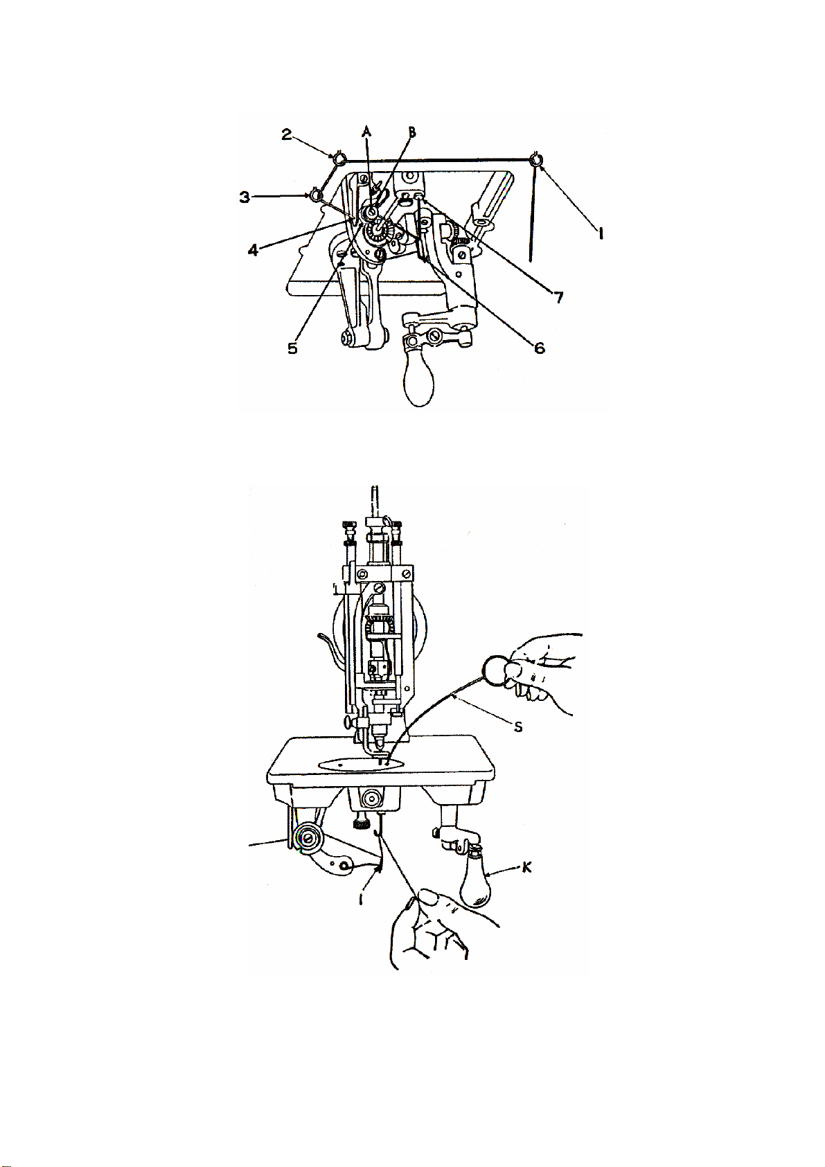
Fig. 4, Threading machine
Fig. 5, Threading machine
8
Page 10
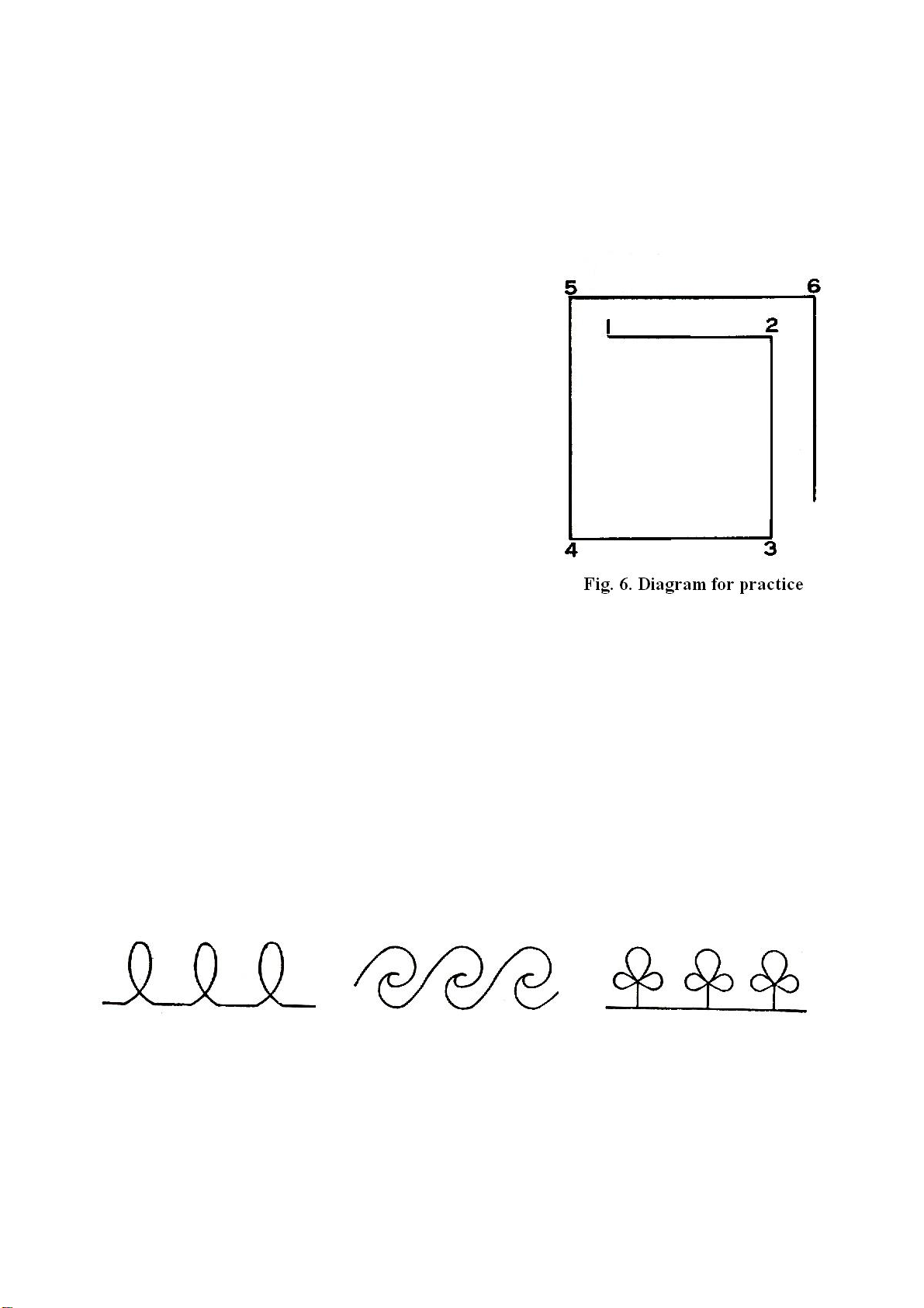
LEARNING TO OPERATE THE MACHINE
NOTE: When in operation the machine pul
ley must always turn over away
from operator.
Mark a design (see Fig. 6) on a 12 inch
square pi
ece of cloth.
Place cloth under presser foot so that
needle will enter cloth at point 1. T
urn handle K,
Fig. 3 to the right and the hook of the needl e
will be turned in the sam e direction. Lower
presser foot, start machine pulley by turning it
over away from you, grasp handle K and pull it
down to st art the machine. With handl e
depressed and to the right, cloth will be fed to
point 2, then turn handle to the front and cl oth
will be fed to point 3, turn handle to the left and
cloth will be fed to point 4, etc.
To stop machine raise handle K. machine will
stop with needle as its
highest point.
TO OPERATE THE MACHINE
The operator should practice embroi deri
illustrated below:
Fig. 7. Designs for beginners
These designs can be sketched on w hite material such as lawn, and by
ng designs similar to those
following them, the operator can soon become proficient enough to attempt
more intri
cate designs or patterns.
9
Page 11

TO REGULATE THE PRESSURE ON THE PRESSER FOOT
The pressure on the presser foot is regulated by the thumb screw C, Fig.
o increase the pressure, turn t he thumb screw over to the right or
3. T
downward. To decrease the pressure, turn the thumb screw over to the lef t
or upward.
TENSIONS
If stitches are too tight, raise needle holder approximately 1/16 i
nch.
Various effects can be produced by changi
ng the height of the needl e
holder as well as by adjusting the length of stitch.
The tension on the threa d is regul
ated by the thum b nut B, Fig. 4 at the
left of the tension discs. T o increase the tension turn this nut over toward
you. To decrease the tension turn this thumb nut over from you. This tension
should be only tight enough to prevent the skipping of stitches.
10
Page 12
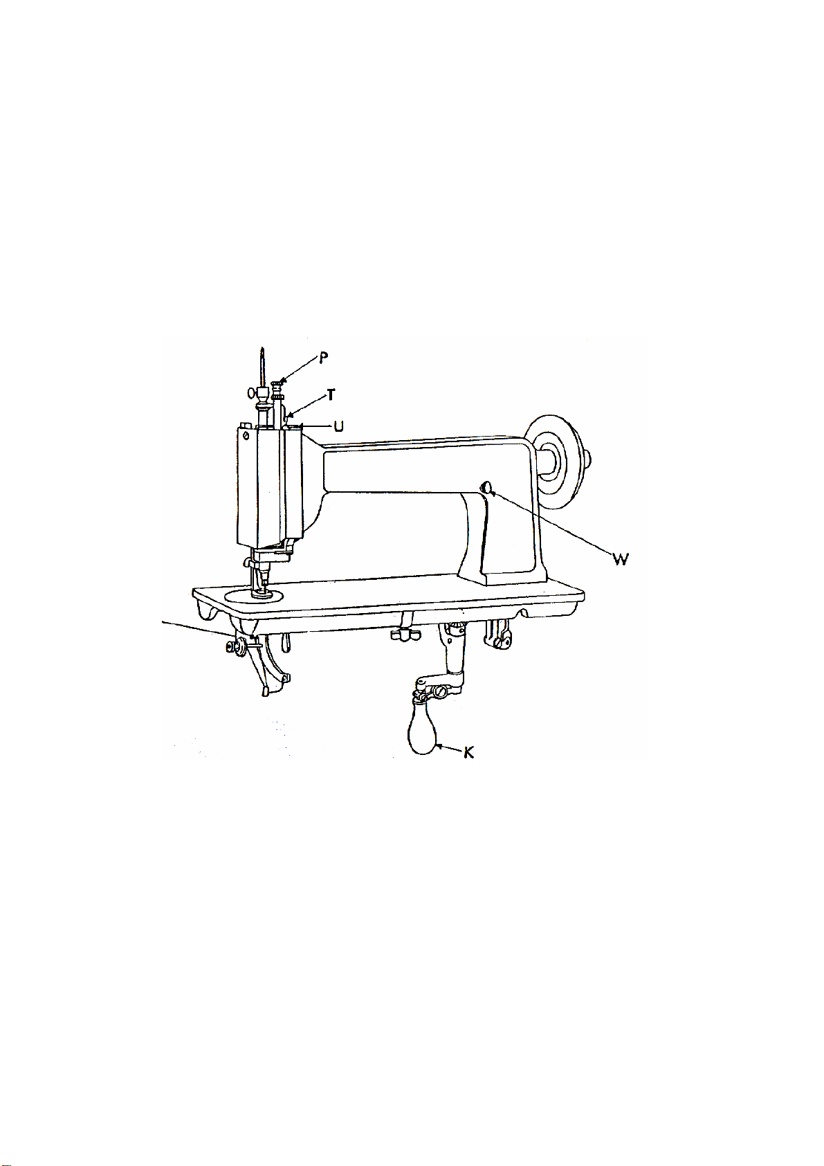
TO ADJSUT THE LENGTH OF STITCH
The length of stitch is adj usted by screw T
, Fig 8. To lengthen the stitch,
loosen locking l ever U and turn screw T over to the l eft or upward, then
tighten locking lever U.
To shorten the stitch, loosen locking lever U and turn the screw T
over to
the right or downward, then tighten locking lever U.
Fig. 8. Adjustments on the machine
11
Page 13

TO REGULATE THE PRESSURE ON THE NIPPLE
The pressure on the nipple is regulated
by the thumb screw P
, Fig. 8 at the top of
the machine. T o increase the pressure,
turn this thumb screw over to the right or
downward. To decrease the pressure,
turn this thumb screw ov er to the lef t or
upward.
NOTE: Too much pressure on the
nipple may cause the thread to break.
When sewing fi ne net it is someti mes
necessary to prevent the nipple from
touchi
ng the needle plate.
To raise the nipple, insert a screw driver
in hole R, Fig. 9 and loosen the set screw
therei
n. The eccentric adjusting stud Q
can then be turned so that nipple can be
set at the desired height; then tighten the
set screw in hole R.
THE LOOPER
Allow the stop motion to throw the machine out of action and make sure
that it is securely held in it
avoid breaking the point of the needl e, remove the needle plate af ter
removing the thumb screw L, Fig. 10 , and observe the notch in the looper
which, when in its correct position, should be at the rear, slightly to the right
of the needle, while the handle K is toward the front.
s locking position. Raise the needle hol der to
12
Page 14

TO SET THE LOOPER
Turn the machine back on it s hinges and turn handl e K, fig. 10 and wing
screw B, Fig. 3 to the front. Loosen set screw X, Fig. 10 of the operating
worm gear Y
, and turn the gear slightly , until the notch in the looper is in its
correct position as instructed above. Af ter having set the worm gear flush
with the end of the looper shaft M, tighten the set screw X.
Fig. 10, Oiling points and adjustments in base of machine
13
Page 15

PILE OR MOSS STITCH
The raised pile or moss stitch or produced by adj
usting the machine so
that it will drop the stitches in loose loops on the material. To accomplish this,
turn handle K to the front , loosen the wing screw B, Fig.3 and turn the
needle holder so that the hook of the needle will pint directly to the back of
the machine, then tighten the wing sc rew. Reach under the bed of the
machine with the left hand, grasp the knurled end Z, Fig. 10 of the operating
worm gear, draw the worm gear to the left and while holding it turn handle K
around to the right directly to the ba ck, the release the knurled and of the
gear.
The looper will then be set in the opposite directi
on to that which i s
required for the chain stitch, or with the notch of the looper at the front of the
needle while handle K is at the front.
By operating the machine and turni ng handl
e K rapidly, so as to make
very small circles of dropped stitch loop s laid one on the other , raised pile
work is produced. The high er the needle is set the longer the loop will be.
The size of the thread and thickness of the m aterial sued will have to be
considered when adjusting the machine for pile stitching.
14
Page 16

15
Page 17

Ref. NO. Parts No. Description
A
A
A
A
A
)
A
)
A
A
A
A
P1-1 8135
P1-2 123
P1-3 8154
P1-4A 8153P1-4B 8153-B
P1-5 8134
P1-6 5227
P1-7 8150
P1-8 8181
RM SIDE COVER
RM SIDE COVER THUMB SCREW
RM POSITION PIN
RM SCREW (LONG
RM SCREW (SHORT
RM HEAD COVER
RM HEAD COVER THUMB SCREW
RM HEAD POSITION PIN
RM SCREW
16
Page 18

17
Page 19

REF. NO. PARTS NO.
A
A
A
A
A
A
A
A
DESCRIPTION
P2-1 8017-B DRIVING PULLEY
P2-2 8015 DRIVING PULLEY SLEEVE
P2-3 8018 DRIVING PULLEY SLEEVE SCREW
P2-4 8016-A DRIVING PULLEY SLEEVE BUSHING
P2-5 98 DRIVING PULLEY SLEEVE BUSHING SCREW
P2-6 8012
P2-7 8013
P2-8 8014
RM SHAFT DRIVING FLANGE WITH SCREWS
RM SHAFT DRIVING FLANGE POSITION SCREW
RM SHAFT DRIVING FLANGE SET SCREW
P2-9 8008 STOP CAM
P2-10 8163 STOP CAM DRIVING STUD
P2-11 8009-A STOP CAM SPRING
P2-12 8010 STOP CAM SPRING COLLAR WITH SET SCREWS
P2-13 132 STOP CAM SPRING COLLAR SET SCREW
P2-14 5266
P2-15 132
P2-16 8003-B
P2-17 98
RM SHAFT COLLAR WITH SET SCREWS
RM SHAFT COLLAR SET SCREW
RM SHAFT BUSHING
RM SHAFT BUSHING SCREW
P2-18 8006 NEEDLE DRIVING CAM ROLLER
P2-19 8005-A NEEDLE DRIVING CAM POSITION SCREW
P2-20 8146 LOOPER OPERATING CAM POSITION PIN
P2-21 813
RM SHAFT WITH LOOPER OPERATING CAM, NEEDLE
DRIVING CAM, ROLLER STUD, POSITION PIN AND
POSITION SCREW
18
Page 20

19
Page 21

REF. NO. PARTS NO.
(
(
(
(
(
(
(
P3-1 8110-A STITCH ROTATING GEAR
P3-2 8142 STITCH ROTATING GEAR
DESCRIPTION
UPPER) WITH SET SCREW
UPPER) SET SCREW
P3-3 8111 STITCH ROTATING GEAR SHAFT
P3-4 8180 STITCH ROTATING GEAR SHAFT BUSHING
P3-5 132 STITCH ROTATING GEAR SHAFT BUSHING SCREW
P3-6 8112-A STITCH ROTATING GEAR
P3-7 8142 STITCH ROTATING GEAR
P3-8 8110-A FEED ROTATING GEAR
P3-9 8142 FEED ROTATING GEAR
LOWER) WITH SET SCREW
LOWER) SET SCREW
UPPER) (REAR) WITH SET SCREW
UPPER) (REAR) SET SCREW
P3-10 8079 STOP BRACKET INTERLOCKING ROD
P3-11 8080 STOP BRACKET INTERLOCKING ROD SPRING
P3-12 8081 STOP BRACKET INTERLOCKING STOP BLOCK
P3-13 121 STOP BRACKET INTERLOCKING STOP BLOCK SCREW
P3-14 8159 STOP BRACKET POSITION PIN
P3-15 8077 STOP CAM ROLLER
P3-16 8078 STOP CAM ROLLER SCREW STUD
P3-17 8075 STOP CAM ROCKING LEVER
P3-18 8076 STOP CAM ROCKING LEVER HINGE SCREW
P3-19 8074 STOP BRACKET
P3-20 8172 STOP BRACKET SCREW
P3-21 8082 STARTING TRIP LEVER SLIDE
P3-22 8084 STARTING TRIP LEVER SLIDE SPRING
P3-23 8083 STRATING TRIP LEVER SLIDE CAP
P3-24 124 STARTING TRIP LEVER SLIDE CAP SCREW
P3-25 801 STOP BRACKET COMPLETE.
REF. NOS.)10.11.12
13.15.16.17.18.19.21.22.23 & 24.
20
Page 22

21
Page 23

REF. NO. PARTS NO
.
A
A
A
A
A
A
A
(
)
(
)
)
(
)
(
)
(
)
(
)
)
)
P4-1 8085-B
P4-2 8177
P4-3 8174
P4-4
P4-4B 8176
P4-5 8178
P4-6 8179
P4-7 5207
P4-8 8089P4-9 8092
P4-10 8093
P4-11 8090
P4-12 8091
P4-13 8088
P4-14 8143
P4-15 8149
P4-16 8094
P4-17 8096P4-18 8142
P4-19 8097P4-20 8142
P4-21 8095-B
P4-22 8098-B
P4-23 129-B
P4-24 8106
P4-25 8107
P4-26 8150
P4-27 8100P4-28 8152
P4-29 129-B
P4-30 8099
P4-31 8158
P4-32 8101
P4-33 124
P4-34 8102
P4-35 8103
P4-36 8104
P4-37 8105
P4-38 802-
P4-39 803
P4-40 804-
P4-41 805
P4-42 806
8175
DESCRIPITON
LOOPER OPERATING CONNECTION
LOOPER OPERATING CONNECTION JOINT
LOOPER OPERATING CONNECTION JOINT PITMAN
LOOPER OPERATING CONNECTION JOINT PITMAN NUT
LOOPER OPERATING CONNECTION JOINT PITMAN NUT (LOWER
LOOPER OPERATING CONNECTION JOINT HINGE STUD
LOOPER OPERATING CONNECTION JOINT HINGE STUD SPRING
WASHER
LOOPER OPERATING CONNECTION JOINT HINGE STUD NUT
LOOPER OPERATING BELL CRANK
LOOPER OPERATING BELL CRANK HINGE BLOCK
LOOPER OPERATING BELL CRANK HINGE BLOCK SCREW
LOOPER OPERATING BELL CRANK HINGE SCREW
LOOPER OPERATING BELL CRANK HINGE SCREW NUT
LOOPER OPERATING BELL CRANK BRACKET
LOOPER OPERATING BELL CRANK BRACKET SCREW
LOOPER OPERATING BELL CRANK BRACKET POSITION PIN
LOOPER OPERATING SHAFT
LOOPER OPERATING SHAFT SLEEVE GEAR WITH SET SCREW
LOOPER OPERATING SHAFT SLEEVE GEAR SET SCREW
LOOPER OPERATING SHAFT SLEEVE AND GEAR WITH SET
LOOPER OPERATING SHAFT SLEEVE AND GEAR SET SCREW
LOOPER OPERATING SHAFT GUIDE
LOOPER OPERATING SHAFT GUIDE BLOCK
LOOPER OPERATING SHAFT GUIDE BLOCK SET SCREW
NEEDLE PLATE
NEEDLE PLATE CLAMPING THUMB SCREW
PRESSER FOOT LIFTING STOP PIN
LOOPER
LOOPER COLLAR WITH SET SCREW
LOOPER COLLAR SET SCREW
LOOPER BRACKET
LOOPER BRACKET SCREW
LOOPER POSITION PLATE
LOOPER POSITION PLATE SCREW
LOOPER OPERATING GEAR
LOOPER OPERATING GEAR SPRING
LOOPER OPERATING COLLAR WITH SET SCREW
LOOPER OPERATING COLLAR SET SCREW
LOOPER OPERATING CONNECTION COMPLETE.
REF. NOS. 1.2.3.4A.4B.5.6.7.8 TWO 9 & TWO 10
LOOPER OPERATING BELL CRANK BRACKET
REF. NOS. 13 WITH 17 TO 23
LOOPER OPERATING BELL CRANK BRACKET COMPLETE.
REF. NOS. 11.12.16.38&39
LOOPER OPERATING GEAR (REF. NOS.) 34 WITH 35, 36 & 37
LOOPER BRACKET COMPLETE (REF. NOS. 27.28.29.30.32&33
SPIRAL
CAM END
UPPER
22
Page 24

23
Page 25

REF. NO. PARTS NO.
A
A
A
A
A
A
A
A
A
A
DESCRIPTION
P5-1 8123 STARTING TRIP LEVER (INTERMEDIATE)
P5-2 8124 STARTING TRIP LEVER (INTERMEDIATE) HINGE SCREW
P5-3 8122 STARTING TRIP LEVER ROD
P5-4 8113 STITCH ROTATING GEAR BRACKET
P5-5 8143 STITCH ROTATING GEAR BRACKET SCREW
P5-6 8149 STITCH ROTATING GEAR BRACKET POSITION PIN
P5-7 8114P5-8 8096-
STITCH ROTATING HAND LEVER SHAFT
STITCH ROTATING HAND LEVER SHAFT GEAR WITH SET SCREW
P5-9 8142 STITCH ROTATING HAND LEVER SHAFT GEAR SET SCREW
P5-10 8117 STITCH ROTATING GEAR BRACKET SHAFT (INTERMEDIATE)
P5-11 8110-
STITCH ROTATING GEAR BRACKET SHAFT (INTERMEDIATE)
GEAR (BACK OR FRONT) WITH SET SCREW
P5-12 8142 STITCH ROTATING GEAR BRACKET SHAFT (INTERMEDIATE)
GEAR (BACK OR FRON)SET SCREW
P5-13 8115-
STITCH ROTATING HAND LEVER WITH SET SCREW
P5-14 5176-C STITCH ROTATING HAND LEVER SET SCREW
P5-15 8118 STITCH ROTATING HAND LEVER HANDLE
P5-16 8116 STITCH ROTATING HAND LEVER HANDLE SLEEVE
P5-17 5070 STITCH ROTATING HAND LEVER HANDLE SLEEVE WASHER
P5-18 8141 STITCH ROTATING HAND LEVER HANDLE SLEEVE SCREW
P5-19 8119 STARTING TRIP LEVER
P5-20 8045 STARTING TRIP LEVER HINGE SCREW
P5-21 8120 STARTING TRIP LEVER BLOCK
P5-22 8121 STARTING TRIP LEVER BLOCK SCREW STUD
P5-23 8125 TENSION BRACKET
P5-24 8143 TENSION BRACKET SCREW
P5-25 8131 TENSION REGULATING LEVER
P5-26 8132P5-27 4140-
TENSION REGULATING LEVER HINGE SCREW
TENSION REGULATING LEVER HINGE SCREW SPRING WASHER
P5-28 8127 TENSION REGULATING PLATE
P5-29 8128 TENSION REGULATING PLATE HINGE SCREW
P5-30 8129P5-31 8130-
TENSION REGULATING SPRING
TENSION REGULATING SPRING SCREW STUD
P5-32 8133-C THREAD CONTROLLER SPRING
P5-33 121 THREAD CONTROLLER SPRING SCREW
P5-34 81 TENSION THUMB NUT
P5-35 5267P5-36 5190-
TENSION SPRING
TENSION DISC
P5-37 8164 TENSION STUD
P5-38 5207 TENSION STUD NUT
P5-39 8126 SPOOL SCREW STUD
P5-40 807 STITCH ROTATING HAND LEVER HANDLE SLEEVE
(REF. NO.) 16 WITH 15.17 &18.
P5-41 808 STITCH ROTATING HAND LEVER
(REF. NO.) 13 WITH 14.19.20.21.22&40
P5-42 809 STITCH ROTATING GEAR BRACKET COMPLETE
(REF. NOS.) 1.2.3.4.7.8.9.10. TWO 11. TWO 12 &41)
P5-43 810 TENSION COMPLETE (REF. NOS.) 34.35. TWO 36. 37 &38)
P5-44 811 TENSION BRACKET COMPLETE
(REF. NOS.) 23.25.26.27.28.29.30.31.32.33&43)
24
Page 26

PARTS FOR 104-3T ONLY
25
Page 27

REF. NO. PARTS NO.
P6-1 8065 PRESSER FOOT SLIDE BAR SPRING
P6-2 8066 PRESSER FOOT SLIDE BAR SPRING PLUNGER
P6-3 8067 PRESSER FOOT SLIDE BAR THUMB SCREW
P6-4 8161
P6-5 8063 PRESSER FOOT SLIDE BAR GUIDE
P6-6 8138 PRESSER FOOT SLIDE BAR GUIDE SET SCREW
P6-7 8064 PRESSER FOOT SLIDE BAR SPRING STOP
P6-8 8139 PRESSER FOOT SLIDE BAR ADJUSTING SCREW
P6-9 8322 PRESSER FOOT SLIDE BAR
P6-10 8140 PRESSER FOOT SLIDE BAR SPRING STOP SCREW
P6-11 8060-A PRESSER FOOT LIFTER
P6-12 8061 PRESSER FOOT LIFTER HINGE SCREW
P6-13 8069-A PRESSER FOOT LEVER SWIVEL
P6-14 5227 PRESSER FOOT LEVER SWIVEL STOP SCREW
P6-15 8070 PRESSER FOOT LEVER SWIVEL HINGE SCREW
P6-16 8323 PRESSER FOOT LEVER
P6-17 8324 PRESSER FOOT
P6-18 8072 PRESSER FOOT CLAMP
P6-19 8025 PRESSER FOOT CLAMP THUMB SCREW
P6-20 8073-A PRESSER FOOT SHOE (RUBBER)
P6-21 8054 NIPPLE CARRIER THUMB SCREW
P6-22 8160 NIPPLE CARRIER THUMB SCREW NUT
P6-23 8317 NIPPLE CARRIER
P6-24 8051 NIPPLE CARRIER LIFTING SCREW STUD
P6-25 8052 NIPPLE CARRIER SPRING
P6-26 8053 NIPPLE CARRIER EXTENSION
P6-27 8318 NIPPLE CARRIER GUIDE
P6-28 8182 NIPPLE CARRIER GUIDE SCREW
P6-29 8319 NIPPLE CARRIER SLEEVE WITH SET SCREWS
P6-30 8320 NIPPLE CLAMPING BLOCK
P6-31 8339 NIPPLE CLAMPING BLOCK SCREW
P6-32 8321 NIPPLE
P6-33 8335 NIPPLE SCREW
PRESSER FOOT SLIDE BAR THUMB SCREW NUT
DESCRIPTION
(PRESSURE REGULATING)
26
Page 28

27
Page 29

REF. NO. PARTS NO.
A
A
A
A
A
A
A
A
A
A
A
P7-1 8303 NEEDLE HOLDER
P7-2 8027 NEEDLE
P7-3 8309
P7-4 8305 NEEDLE HOLDER OPERATING COLLAR
P7-5 8306 NEEDLE HOLDER GUIDE BLOCK
P7-6 8307 NEEDLE HOLDER THUMB SCREW
P7-7 8333 NEEDLE HOLDER GUIDE BLOCK SCREW
P7-8 8308
P7-9 5176-A
P7-10 8047 FEED REGULATING SCREW
P7-11 8048 FEED REGULATING SCREW LOCK LEVER NUT
P7-12 8304 NEEDLE HOLDER OPERATING SLIDE
P7-13 8301
P7-14 8020
P7-15 8021
P7-16 8022
P7-17 8150
P7-18 8145
P7-19 8302 NIPPLE CARRIER SLEEVE BUSHING
P7-20 8030
P7-21 129-B
P7-22 8312 FEED LEVER
P7-23 8314 FEED LEVER HINGE SCREW STUD
P7-24 8315 FEED LEVER BRACKET GUIDE
P7-25 8316 FEED LEVER BRACKET GUIDE CAP
P7-26 8136 FEED LEVER BRACKET GUIDE CAP SCREW
P7-27 8313 FEED LEVER BRACKET
P7-28 8335 FEED LEVER BRACKET SET SCREW
P7-29 8036 FEED RECOVERING SPRING (LEFT)
P7-30 8037 FEED RECOVERING SPRING (RIGHT)
P7-31 8038 FEED RECOVERING SPRING SCREW
P7-32 124 FEED LEVER BRACKET SET SCREW
P7-33 8311 FEED SLIDE BLOCK
P7-34 8310-A FEED SLIDE BAR
RM HEAD SLEEVE
RM HEAD SLEEVE CAP
RM HEAD SLEEVE CAP SCREW
RM HEAD
RM HEAD SCREW (UPPER) (LONG)
RM HEAD SCREW UPPER (SHORT)
RM HEAD SCREW (LOWER)
RM HEAD POSITION PIN
RM HEAD POSITION PIN
RM HEAD SLEEVE GEAR WITH SET SCREW
RM HEAD SLEEVE GAER SET SCREW
DESCRIPTION
28
Page 30

29
Page 31

REF. NO. PARTS NO.
A
A
A
A
A
A
A
A
A
A
P8-1 8057 NIPPLE CARRIER BELL CRANK
P8-2 8058 NIPPLE CARRIER BELL CRANK HINGE STUD
P8-3 5225-C NIPPLE CARRIER BELL CRANK HINGE STUD SET SCREW
P8-4 8023 NEEDLE OPERATING SLIDE
P8-5 8028
P8-6 5176P8-7 8042 FEED BELL CRANK
P8-8 8043 FEED BELL CRANK HINGE STUD
P8-9 5225-C FEED BELL CRANK HINGE STUD SET SCREW
P8-10 8046 FEED BELL CRANK SPRING
P8-11 8044 FEED BELL CRANK ROLLER
P8-12 8045 FEED BELL CRANK ROLLER SCREW
P8-13 8059 PRESSER FOOT SLIDE BELL CRANK
P8-14 8058 PRESSER FOOT SLIDE BELL CRANK HINGE STUD
P8-15 8225-C PRESSER FOOT SLIDE BELL CRANK HINGE STUD SET SCREW
P8-16 8060P8-17 8061 PRESSER FOOT LIFTER HINGE SCREW
P8-18 8055 NIPPLE CARRIER GUIDE
P8-19 8182 NIPPLE CARRIER GUIDE SCREW
P8-20 8108 FEED ROTATING SHAFT
P8-21 8109 FEED ROTATING SHAFT GEAR
P8-22 8147 FEED ROTATING SHAFT GEAR POSITION PIN
P8-23 8019
P8-24 8029P8-25 8026-B NEEDLE HOLDER
P8-26 8024 NEEDLE HOLDER CLAMPING SLEEVE
P8-27 8025 NEEDLE HOLDER CLAMPING SLEEVE THUMB SCREW
P8-28 8031 FEED SLIDE BAR
P8-29 8049 NIPPLE CARRIER
P8-30 8050 NIPPLE CARRIER SLEEVE
P8-31 8151 NIPPLE CARRIER SLEEVE BUSHING
P8-32 8051 NIPPLE CARRIER LIFTING SCREW STUD
P8-33 8062 PRESSER FOOT SLIDE BAR
P8-34 8063 PRESSER FOOT SLIDE BAR GUIDE
P8-35 8139 PRESSER FOOT SLIDE BAR ADJUSTING SCREW
P8-36 8020
P8-37 8021
P8-38 8022
P8-39 8047 FEED REGULATING SCREW
P8-40 8048 FEED REGULATING SCREW LOCK LEVER NUT
RM HEAD SLEEVE CAP
RM HEAD SLEEVE CAP SCREW
PRESSER FOOT LIFTER
RM HEAD
RM HEAD SLEEVE
RM HEAD SCREW (UPPER) (LONG)
RM HEAD SCREW (UPPER) (SHORT)
RM HEAD SCREW (LOWER)
DESCRIPTION
30
Page 32

31
Page 33

REF. NO. PARTS NO.
P8-41 8030 A
P8-42 129-B
P8-43 8138 PRESSER FOOT SLIDE BAR GUIDE SET SCREW
P8-44 8064 PRESSER FOOT SLIDE BAR SPRING STOP
P8-45 8140 PRESSER FOOT SLIDE BAR SPRING STOP SCREW
P8-46 8054 NIPPLE CARRIER THUMB SCREW
P8-47 8160 NIPPLE CARRIER THUMB SCREW NUT
P8-48 8052 NIPPLE CARRIER SPRING
P8-49 8053 NIPPLE CARRIER EXTENSION
P8-50 8067 PRESSER FOOT SLIDE BAR THUMB SCREW
P8-51 8161 PRESSER FOOT SLIDE BAR THUMB SCREW NUT
P8-52 8065 PRESSER FOOT SLIDE BAR SPRING
P8-53 8066 PRESSER FOOT SLIDE BAR SPRING PLUNGER
P8-54 8033 FEED SLIDE BLOCK (FOR 104-1T)
8033-
A FEED SLIDE BLOCK (FOR 104-2T)
P8-55 8034P8-56 8144 FEED LEVER HINGE PIN
P8-57 8035 FEED LEVER BRACKET
P8-58 129-B FEED LEVER BRACKET SET SCREW
P8-59 124 FEED LEVER BRACKET SET SCREW
P8-60 8036 FEED RECOVERING SPRING (LEFT)
P8-61 8037 FEED RECOVERING SPRING (RIGHT)
P8-62 8038 FEED RECOVERING SPRING SCREW
P8-63 8068
P8-64 8069P8-65 8070P8-66 8188 PRESSER FOOT LEVER SWIVEL STOP SCREW
P8-69 8039 FEED LEVER BRACKET GUIDE
P8-70 8040 FEED LEVER BRACKET GUIDE CAP
P8-71 8136 FEED LEVER BRACKET GUIDE CAP SCREW
P8-72 8071P8-73 8073P8-74 8072 PRESSER FOOT CLAMP
P8-75 8025 PRESSER FOOT CLAMP THUMB SCREW
P8-76 8145
P8-77 8056 NIPPLE
A FEED LEVER
A PRESSER FOOT LEVER SWIVEL
A PRESSER FOOT LEVER SWIVEL HINGE SCREW
A PRESSER FOOT
A PRESSER FOOT SHOE (RUBBER)
ARM HEAD SLEEVE GEAR SET SCREW
PRESSER FOOT LEVER WITH FEED LEVER BRACKET
GUIDE BEARING AND PIN
ARM HEAD POSITION PIN
DESCRIPTION
RM HEAD SLEEVE GEAR WITH SET SCREW
32
Page 34

33
Page 35

REF. NO. PARTS NO.
A
DESCRIPTION
P9-1 8336 CORD SPOOL
P9-2 8331 CORD SPOOL SPINDLE
P9-3 CORD SPOOL SPINDLE THUMB NUT
P9-4 CORD SPOOL SUPPORT
P9-5 CORD SPOOL SUPPORT
P9-6 NUT
P9-7 8329 CORD SPOOL FRICTION SPRING
P9-8
DJUSTING SCRW
P9-9 8140 CORD SPOOL FRICTION SPRING SCRW
P9-10
P9-11 SCREW
P9-12 CORD SPOOL SPINDLE BASE
P9-13 SCREW
P9-14 CORD SPOOL BRACKET SLEEVE WITH SCREW
P9-15 SCREW
P9-16 SCREW
P9-17
P9-18
34
Page 36

35
Page 37

REF. NO. PARTS NO.
A
A
A
(
)
(
)
(
)
A
A
A
)
P10-1
P10-2
P10-3
C01 SCREW DRIVER
C02 SCREW DRIVER
C03 SCREW DRIVER
P10-4 8073-A PRESSER FOOT SHOE
P10-5 8170 TWEEZERS
※
P10-6-1 8056-1 NIPPLE
※
P10-6-2 8056-2 NIPPLE
※
P10-6-3 8056-3 NIPPLE
※
P10-6-4 8056-4 NIPPLE
※
DESCRIPTION
RUBBER
P10-6-5 8056-5 NIPPLE
P10-6-6 8056-6 NIPPLE
※
P10-7 8027S NEEDLE
253C
P10-8 8171 PLIERS
P10-10 8169 MACHINE REST PIN (WOOD)
※
P10-11 8167 CLEANING WIRE
P10-12 8156-A THREAD WIRE
※
P10-13 8156 THREAD WIRE
P10-14 8071-B-B PRESSER FOOT
P10-15
P10-16
P10-17 8157 BED CLAMPING THUMB SCREW
※
P10-18 8166 SCREW EYE
※
C-04A OILER
C05 OIL
SPUR
P10-19 8155 NIPPLE WRENCH
P10-20 8165 MACHINE HINGE CONNECTION
P10-21
C06 WRENCH (3m/m
EXTRA ACCESSORIES
※
36
Page 38

 Loading...